Table of Contents
Advertisement
Quick Links
Advertisement
Table of Contents

Related Manuals for ABB ACS880-604


Summary of Contents for ABB ACS880-604
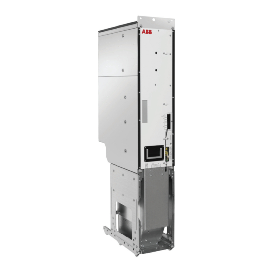
- Page 1 — ABB INDUSTRIAL DRIVES ACS880-604 3-phase brake units as modules Hardware manual...
- Page 3 ACS880-604 3-phase brake units as modules Hardware manual Table of contents 4. Cabinet construction 6. Electrical installation 9. Start-up © 2019 ABB Oy. All Rights Reserved. 3AXD50000022033 Rev D EFFECTIVE: 2019-09-30...
-
Page 5: Table Of Contents
Table of contents 5 Table of contents 1 Introduction to the manual Contents of this chapter ................Applicability ..................Safety instructions ................Target audience ................... Related documents ................Categorization by frame size and option code ..........Use of component designations ..............Terms and abbreviations ................. - Page 6 6 Table of contents One R8i module in a 600 mm wide Rittal VX25 enclosure without DC switch/disconnector ................One R8i module in a 600 mm wide Rittal VX25 enclosure with DC switch/disconnector . Overview of kits ................... Stage 1: Installation of common parts ............Stage 2A: Installation of DC busbars (1) (without DC switch or charging) ....
- Page 7 Table of contents 7 Default I/O diagram of the brake control unit ..........External power supply for the control unit (XPOW) .......... DI6 as a PTC sensor input ..............AI1 or AI2 as a Pt100, Pt1000, PTC or KTY84 sensor input ....... DIIL input ...................
- Page 8 8 Table of contents DC connection flanges and busbars ............DC fuses ..................DC switch/disconnector kits ..............Charging kits ................... Charging resistors ................Resistor-side components ............... Quick connector and outgoing resistor busbars .......... Incoming resistor busbars ..............Resistor fuses .................. Cabinet ventilation ................
- Page 9 Table of contents 9 Control electronics ................BCU control unit ................DPMP-01 door mounting kit ..............DC fuse blocks (Bussmann) ..............Switchgear and charging components ............Switch fuses ..................OS100GJ04FP ................OS160GD04F ................Switch/disconnectors ................. OT1200U11 and OT1600E11 ............Switch handles ................. OHB65J6 ..................
-
Page 11: Introduction To The Manual
Introduction to the manual Contents of this chapter This chapter gives basic information on the manual. Applicability The manual is applicable to ACS880-604 3-phase brake modules intended for user-defined cabinet installations. Safety instructions Obey all safety instructions delivered with the drive. -
Page 12: Related Documents
ACS880 primary control program firmware manual 3AUA0000085967 ACS880 primary control program quick start-up guide 3AUA0000098062 Brake module and DC/DC converter module manuals ACS880-604 1-phase brake chopper modules hardware manual 3AUA0000106244 ACS880-604 3-phase brake modules hardware manual 3AXD50000022033 ACS880 (3-phase) brake control program firmware manual... -
Page 13: Categorization By Frame Size And Option Code
Introduction to the manual 13 Categorization by frame size and option code Some descriptions, instructions, technical data and dimensional drawings which concern only certain brake units are marked with the symbol of the frame size such as 4×R8i. The marking derives from the quantity and basic construction of the brake chopper modules that form the brake unit. - Page 14 14 Introduction to the manual Term/ Description Abbreviation Inverter module Inverter bridge, related components and drive DC link capacitors enclosed in a metal frame or enclosure. Intended for cabinet installation. Inverter unit Inverter module(s) under control of one control board, and related components. One inverter unit typically controls one motor.
-
Page 15: Operation Principle And Hardware Description
Product overview The ACS880-604 is an air-cooled brake unit as modules. The brake unit as modules range contains components for building the brake unit(s) to be used in a common DC bus system drive. The brake unit as modules includes a brake chopper module or several parallel-connected brake chopper modules. -
Page 16: Simplified Main Circuit Diagram Of The Drive System
16 Operation principle and hardware description • a backup for the regenerative supply unit is needed. Simplified main circuit diagram of the drive system This diagram shows a typical common DC bus drive system. t° AC supply Input (AC) fuses Supply unit DC bus Inverter DC fuses (with or without a DC switch/disconnector) -
Page 17: Brake Module Hardware
Operation principle and hardware description 17 The supply unit connects to the AC supply network. The supply unit converts the AC voltage into DC. The DC voltage is distributed through the DC bus to all inverter and brake units. The inverter unit, consisting of one or more inverter modules, converts the DC back to AC that rotates the motor. -
Page 18: Connectors X50
BCU control unit. It is not allowed to use the 24 V DC output on terminal X53 for any other purpose than for powering the BCU control unit. If the unit consists of parallel-connected R8i modules, ABB recommends to use an external 24 V DC supply to power the BCU control unit. -
Page 19: Fibre Optic Connectors
Operation principle and hardware description 19 Connectors X51, X52, X53 STO IN STO connectors of the mod- STO IN ule. Must be connected to 24 V DC for the module to start. 24V OUT 24 V DC for BCU and for 24V OUT STO IN to enable the mod- ule operation. -
Page 20: Overview Circuit Diagram Of The Brake Unit
The following figure shows a simplified connection example of a brake unit. Item Explanation Available through Brake unit cabinet DC link DC- fuses ABB or third party DC+ fuses ABB or third party Brake resistor fuses ABB or third party Brake chopper module R8i Brake resistors cabinet... -
Page 21: Frame R8I Layout
Operation principle and hardware description 21 Frame R8i layout This figure shows the layout of the R8i module. R8i module, front R8i module, back DC busbars Handle LEDs and fiber optic connectors Fan (standard speed-controlled fan shown; a direct-on-line fan is available as option +C188) Quick connector (three phases). -
Page 22: Overview Of Power And Control Connections
22 Operation principle and hardware description Overview of power and control connections The diagram below shows the power and control connections of the brake unit consisting of one 3-phase brake module. For parallel-connected brake modules, the brake resistors are connected to each brake module also as shown below. Brake module cubicle DC switch/disconnector with charging circuit Control unit... -
Page 23: Brake Unit Control Devices
Operation principle and hardware description 23 Brake unit control devices Each brake chopper module employs a dedicated control unit (BCU) that contains the BCON board with basic I/Os and slots for optional modules. A fiber optic link connects the BCU to the brake chopper module. -
Page 24: The Control Panel
24 Operation principle and hardware description ■ The control panel The control panel (optional) is the user interface of the brake unit, providing the essential controls such as reset, and the parameter settings for the control program. The control panel can be mounted on the cabinet door using a DPMP-01 mounting platform (available separately). -
Page 25: Inverter Module Type Designation Label
Operation principle and hardware description 25 Inverter module type designation label Each module has a type designation label attached to it. The type designation stated on the label contains information on the specifications and configuration of the module. The first digits express the basic construction, for example “ACS880-104-0100A-3”. Any optional selections are given thereafter, separated by plus signs. -
Page 26: Type Designation Of The Module
26 Operation principle and hardware description Type designation of the module Type designation describes the composition of the module in short. The complete designation code is divided in subcodes: • The first digits form the basic code. It describes the basic construction of the module. The fields in the basic code are separated by hyphens. -
Page 27: Moving And Unpacking The Module
Moving and unpacking the module 27 Moving and unpacking the module Contents of this chapter This chapter gives basic information on moving, unpacking and lifting the modules. WARNING! Obey the safety instructions of the drive. If you ignore them, injury or death, or damage to the equipment can occur. -
Page 28: Moving The Modules
28 Moving and unpacking the module Moving the modules WARNING! For general safety instructions for moving the module, see ACS880 multidrive cabinets and modules safety instructions (3AUA0000102301 [English]). -
Page 29: Cabinet Construction
The installation must always be designed and made according to applicable local laws and regulations. ABB does not assume any liability whatsoever for any installation which breaches the local laws and/or other regulations. Furthermore, if the recommendations given by ABB are not followed, the drive may experience problems that the warranty does not cover. - Page 30 You can find the kit-specific assembly drawings, step-by-step instructions and kit information on the Internet. Go to https://sites-apps.abb.com/sites/lvacdrivesengineeringsupport/content. If needed, contact your local ABB representative. The example includes also cabinet assembly drawings that show each stage listed in the table. More detailed steps of each stage are described in the kit-specific assembly drawings.
-
Page 31: One R8I Module In A 600 Mm Wide Rittal Vx25 Enclosure Without Dc Switch/Disconnector
Cabinet construction 31 One R8i module in a 600 mm wide Rittal VX25 enclosure without DC switch/disconnector DC fuses BCU-02 brake control unit Brake chopper module Terminals for brake resistor cable connection Brake chopper module cooling fan Cable entries for brake resistor and control cables Brake resistor fuses... -
Page 32: One R8I Module In A 600 Mm Wide Rittal Vx25 Enclosure With Dc Switch/Disconnector
32 Cabinet construction One R8i module in a 600 mm wide Rittal VX25 enclosure with DC switch/disconnector DC fuses Cable entries for brake resistor and control cables Brake chopper module Terminals for brake resistor cable connection Brake chopper module cooling fan DC switch/disconnector behind the plate Brake resistor fuses Charging switch with fuses behind the plate... - Page 33 Cabinet construction 33 Parts to be installed Instruction code Kit code Kit ordering code Common parts: 3AXD50000336340 • Baying parts 3AXD50000336104 • PE busbar 3AXD50000336692 • Divider panel 3AXD50000333639 A-468-X-001-VX 3AXD50000333387 • DC busbars DC connection 1 of 2 (busbars from DC bus to DC fuses and flanges from DC fuses to brake chopper module) 3AXD50000493555 A-6-8-262-VX...
-
Page 34: Overview Of Kits
34 Cabinet construction Overview of kits... -
Page 35: Stage 1: Installation Of Common Parts
Cabinet construction 35 Stage 1: Installation of common parts... -
Page 36: Stage 2A: Installation Of Dc Busbars (1) (Without Dc Switch Or Charging)
36 Cabinet construction Stage 2A: Installation of DC busbars (1) (without DC switch or charging) -
Page 37: Stage 2B: Installation Of Dc Busbars (1) (With Dc Switch And Charging)
Cabinet construction 37 Stage 2B: Installation of DC busbars (1) (with DC switch and charging) -
Page 38: Stage 3: Installation Of Quick Connector And Outgoing Resistor Busbars (Cable Connection)
38 Cabinet construction Stage 3: Installation of quick connector and outgoing resistor busbars (cable connection) -
Page 39: Stage 4: Installation Of Incoming Resistor Busbars (Cable Connection)
Cabinet construction 39 Stage 4: Installation of incoming resistor busbars (cable connection) -
Page 40: Stage 5: Installation Of Mounting Plates And Cable Entries
40 Cabinet construction Stage 5: Installation of mounting plates and cable entries... -
Page 41: Stage 6: Installation Of Support Plate
Cabinet construction 41 Stage 6: Installation of support plate... -
Page 42: Stage 7: Installation Of Shrouding
42 Cabinet construction Stage 7: Installation of shrouding... -
Page 43: Stage 8: Installation Of Brake Chopper Module
Cabinet construction 43 Stage 8: Installation of brake chopper module... -
Page 45: Guidelines For Planning The Electrical Installation
The installation must always be designed and made according to applicable local laws and regulations. ABB does not assume any liability whatsoever for any installation which breaches the local laws and/or other regulations. Furthermore, if the recommendations given by ABB are not followed, the drive may experience problems that the warranty does not cover. -
Page 46: Selecting And Routing The Brake Resistor Cables
See the technical data. ■ EMC compliance of the complete installation Note: ABB has not verified that the EMC requirements are fulfilled with external user-defined brake resistors and cabling. The EMC compliance of the complete installation must be considered by the customer. -
Page 47: Selecting The Resistor Thermal Switch Circuit Cable
Guidelines for planning the electrical installation 47 • the temperature of the room the resistor is located in does not exceed the allowed maximum. Supply the resistor with cooling air or coolant according to the resistor manufacturer’s instructions. WARNING! The materials near the brake resistor must be non-flammable. The surface temperature of the resistor is high. -
Page 49: Electrical Installation
Electrical installation 49 Electrical installation Contents of this chapter This chapter contains instructions on wiring the brake units. -
Page 50: Electrical Safety Precautions
50 Electrical installation Electrical safety precautions These electrical safety precautions are for all personnel who do work on the drive, motor cable or motor. WARNING! Obey these instructions. If you ignore them, injury or death, or damage to the equipment can occur. If you are not a qualified electrician, do not do installation or maintenance work. -
Page 51: General Notes
Electrical installation 51 General notes ■ Static electricity WARNING! Use a grounding wrist band when you handle printed circuit boards. Do not touch the boards unnecessarily. The boards contain components sensitive to electrostatic discharge. ■ Optical components WARNING! Obey these instructions. If you ignore them, damage to the equipment can occur. •... -
Page 52: Connecting The Brake Resistor Cables And Thermal Switch
52 Electrical installation Connecting the brake resistor cables and thermal switch ■ Connection diagram This diagram shows the brake resistor cable connections and an example connection of the thermal switches. The diagram also shows the internal connections of the brake chopper module cubicle to be done by the system integrator. -
Page 53: Connection Procedure Of The Brake Chopper Cubicle
Electrical installation 53 ■ Connection procedure of the brake chopper cubicle WARNING! Obey the safety instructions of the drive. If you ignore them, injury or death, or damage to the equipment can occur. If you are not a qualified electrical professional, do not do installation or maintenance work. -
Page 54: Connection Procedure Of The Thermal Switch Cable
2. Run the sensor cable inside the brake unit cubicle. 3. ABB recommends that you ground the cable shield 360° at the cable entry. 4. Run the cable to its connection point using existing trunking wherever possible. Protect the cables against any sharp edges or hot surfaces. -
Page 55: Connecting A Pc
Electrical installation 55 Connecting a PC WARNING! Do not connect the PC directly to the control panel connector of the control unit as this can cause damage. A PC (with eg, the Drive composer PC tool) can be connected as follows: 1. -
Page 57: Control Unit
Control unit 57 Control unit Contents of this chapter This chapter • describes the connections of the control unit • contains the specifications of the inputs and outputs of the control unit. General Each brake module is controlled by a dedicated BCU control unit. The control unit consists of a BCON-12 control board (and a BIOC-01 I/O connector board and power supply board) built in a metal housing. -
Page 58: Bcu-X2 Control Unit Layout And Connections
58 Control unit BCU-x2 control unit layout and connections Description I/O terminals (see following diagram) SLOT 1 I/O extension, encoder interface or fieldbus adapter module connection. (This is the sole location for an FDPI-02 diagnostics and panel interface.) SLOT 2 I/O extension, encoder interface or fieldbus adapter module connection SLOT 3... - Page 59 Control unit 59 Description Analog inputs Analog outputs Digital inputs, Digital input interlock (DIIL) XRO3 XD24 XPOW XDIO Digital input/outputs XD2D Drive-to-drive link XRO2 XD24 +24 V output (for digital inputs) XDIO XETH Ethernet port – Not in use XPOW External power input XRO1 XRO1...
-
Page 60: Default I/O Diagram Of The Brake Control Unit
60 Control unit Default I/O diagram of the brake control unit The diagram below shows the default I/O connections on the brake control unit, and describes the use of the signals/connections.See also example circuit diagrams. The wire size accepted by all screw terminals (for both stranded and solid wire) is 0.5 … 2.5 mm (24…12 AWG). -
Page 61: External Power Supply For The Control Unit (Xpow)
Control unit 61 Notes: Default use of the signal in the control program. The use can be changed by a parameter. See also the delivery-specific circuit diagrams. Current [0(4)…20 mA, R = 100 ohm] or voltage [0(2)…10 V, R > 200 kohm] input selected by switch AI1. -
Page 62: Ai1 Or Ai2 As A Pt100, Pt1000, Ptc Or Kty84 Sensor Input
62 Control unit AI1 or AI2 as a Pt100, Pt1000, PTC or KTY84 sensor input Three Pt100/Pt1000 sensors or one KTY84 sensor for motor temperature measurement can be connected between an analog input and output as shown below. (Alternatively, you can connect the KTY to an FIO-11 or FAIO-01 analog I/O extension module or FEN-xx encoder interface module.) At the sensor end of the cable, leave the shields unconnected or ground them indirectly via a high-frequency capacitor with a few nanofarads, for example... -
Page 63: Safe Torque Off (Xsto, Xsto Out)
(nominal impedance 100 to 165 ohm, for example Belden 9842) for the wiring. For best immunity, ABB recommends high quality cable. Keep the cable as short as possible. Avoid unnecessary loops and parallel runs near power cables such as motor cables. -
Page 64: Connector Data
64 Control unit Connector data Power supply (XPOW) Connector pitch 5 mm, wire size 2.5 mm 24 V (±10%) DC, 2 A External power input. Two supplies can be connected for redundancy. Relay outputs RO1…RO3 Connector pitch 5 mm, wire size 2.5 mm (XRO1…XRO3) 250 V AC / 30 V DC, 2 A Protected by varistors... - Page 65 Control unit 65 Analog inputs AI1 and AI2 Connector pitch 5 mm, wire size 2.5 mm (XAI:4 … XAI:7). Current input: –20…20 mA, R = 100 ohm Current/voltage input mode selection by Voltage input: –10…10 V, R > 200 kohm switches Differential inputs, common mode range ±30 V Sampling interval per channel: 0.25 ms...
-
Page 66: Bcu-X2 Ground Isolation Diagram
66 Control unit Control units of the drive 137 ■ BCU-x2 ground isolation diagram Ground isolation diagram XPOW +24VI +24VI +VREF -VREF AGND AI1+ Common mode voltage AI1- AI2+ between each AI input and AI2- AGND is +30 V AGND AGND XD2D BGND... -
Page 67: Installation Checklist
Installation checklist 67 Installation checklist Contents of this chapter This chapter contains a checklist of the mechanical and electrical installation of the drive. Checklist Examine the mechanical and electrical installation of the drive before start-up. Go through the checklist together with another person. WARNING! Obey the safety instructions of the drive. - Page 68 68 Installation checklist Make sure that … If the drive is connected to a network other than a symmetrically grounded TN-S system: You have done all the required modifications (for example, you may need to disconnect the EMC filter or ground- to-phase varistor).
-
Page 69: Start-Up
Start-up 69 Start-up Contents of this chapter This chapter contains the start-up procedure of the brake unit. The symbols in brackets, for example [Q1], refer to the item designations used in the circuit diagrams. These instructions do not cover all start-up tasks of all possible variants of the brake unit. Always refer to the unit-specific circuit diagrams when proceeding with the start-up. - Page 70 70 Start-up Tasks Make sure that the inverter units of the drive system have been installed and started up according to the instructions in their hardware manual. Make sure that the supply unit is stopped, and the drive system has been isolated from the supply network.
-
Page 71: Fault Tracing
Check sensor. Replace faulty sensor. Short circuit in resistor or power cables. Check power cables and resistor. Chopper control board failure. Chopper Contact local ABB representative. damaged; it is not able to disconnect resistor from intermediate circuit. Chopper does not function. -
Page 72: Leds
72 Fault tracing Fault indication/Fault Cause What to do Chopper starts to function at Chopper voltage setting too low. Check voltage setting. too low a DC voltage. Inverter trips on fault 3210 DC Chopper voltage setting too high. Check voltage setting. link overvoltage. -
Page 73: R8I Module Leds
Fault tracing 73 ■ R8i module LEDs Frame R8i modules have three LEDs. For their indications, see the following table. Location Indication R8i module FAULT There is an active fault in the module. (continuous red) ENABLE / STO The module is ready for use. (continuous green) ENABLE / STO XSTO connectors are de-energized. -
Page 75: Maintenance
Maintenance 75 Maintenance Contents of this chapter This chapter refers to the maintenance instructions of the brake unit. Maintenance intervals See ACS880-104 inverter modules hardware manual (3AUA0000104271 [English]). Maintenance instructions See ACS880-104 inverter modules hardware manual (3AUA0000104271 [English]). -
Page 77: Ordering Information
Note: • This chapter only lists the installation accessories available from ABB. All other parts must be sourced from a third party (such as Rittal) by the system integrator. For a listing, refer to the kit-specific installation instructions available at https://sites-apps.abb.com/sites/lvacdrivesengineeringsupport/content. - Page 78 78 Ordering information • w = cabinet width • 4 = 400 mm • 6 = 600 mm • 8 = 800 mm • s = module frame size / sizes • 1 = R1i • 2 = R2i • 3 = R3i •...
-
Page 79: Brake Modules
Brake module type Frame size Contents = 400 V (Range 380 … 415 V): • brake module(s) (frame R8i) with speed-controlled cooling fan(s) ACS880-604-0500-3 • internal du/dt filter (option +E205, included in the module ACS880-604-0750-3 delivery as standard) ACS880-604-1000-3 2×R8i ACS880-604-1510-3 2×R8i... -
Page 80: Control Panel
80 Ordering information Control panel The control panel is not included with the module but must be ordered separately. One control panel is required for the commissioning of an ACS880 drive system, even if the Drive composer PC tool is used. The control panel can be flush mounted on the cabinet door with the help of a door mounting kit. -
Page 81: Control Electronics
You must connect the control unit to each brake chopper module with a pair of fiber optic cables. You can order them from ABB. You can supply 24 V DC for the control unit from the brake module. Alternatively, you can take the power supply from another suitable power source. -
Page 82: Fiber Optic Cables
82 Ordering information ■ Fiber optic cables The following kits, each consisting of a pair of plastic fiber optic cables, are available from ABB: Length Kit type designation Ordering code NLWC-02 58988821 NLWC-03 58948233 NLWC-05 58948250 NLWC-07 58948268 10 m... -
Page 83: Mechanical Installation Accessories
Ordering information 83 Mechanical installation accessories ■ Module installation parts Module installation parts include, for example, side and bottom supports and cable entries for bottom plate for the modules. Note: The designs presented in this manual for Rittal VX25 enclosures employ the Rittal Flat-PLS busbar system. -
Page 84: Shrouds
84 Ordering information Frame Illustration Enclosure Ordering code Kit code size 600 mm 3AXD50000489077 A-6-8-400-VX Instruction code: 3AXD50000493579 ■ Shrouds Shrouds are used for IP20 touch protection with the cabinet doors open. Frame Enclosure Ordering code Kit code Illustration size 600 mm 3AXD50000504725 A-6-8-358-VX... -
Page 85: Dc-Side Components
Ordering information 85 DC-side components ■ Common DC Flat-PLS assembly The brackets in this kit act as a mounting base for the busbar supports of the Rittal Flat-PLS DC bus and ensure its correct placement and alignment inside the cabinet line-up. Note: The designs presented in this manual for Rittal VX25 enclosures employ the Rittal Flat-PLS busbar system. -
Page 86: Dc Fuses
R8i. The fuses listed below are size 3. Fuse (IEC and UL) Brake unit type Type Data Ordering code = 400 V ACS880-604-0500-3 170M6410 2×2 630 A; 690 V 68335418 ACS880-604-0750-3 170M6414 2×2 1000 A; 690 V... -
Page 87: Dc Switch/Disconnector Kits
Ordering information 87 ■ DC switch/disconnector kits IEC– 230 V 60 Hz Brake unit type ACS880-604-… Frame Ordering code Switch type 0500-3 0630-5 0870-7 0750-3 0940-5 1300-7 1000-3 1260-5 1730-7 2×R8i 1510-3 1880-5 2600-7 2×R8i 3AXD50000009534 OT1600E11 2260-3 2830-5 3900-7 3×R8i... -
Page 88: Charging Kits
(with shaft, handle, terminal shrouds and a set of auxiliary contacts), fuses, connectors and the charging controller. Note that the charging resistors or fiber optic cables are not included in the kit and must be ordered separately. Brake unit type ACS880-604-… Frame Ordering code... -
Page 89: Charging Resistors
Ordering information 89 ■ Charging resistors IEC/UL Brake unit type ACS880-604-… Frame Ordering code Data 0500-3 0630-5 0750-3 0940-5 1000-3 1260-5 2×R8i 1510-3 1880-5 2×R8i 10037531 ZRF 30X165S24R 2260-3 2830-5 3×R8i 3010-3 3770-5 4×R8i 3770-3 4710-5 5×R8i 0870-7 1300-7 1730-7 2×R8i... -
Page 90: Incoming Resistor Busbars
90 Ordering information Frame Enclosure Ordering code Kit code Illustration size 600 mm 3AXD50000489213 A-6-8-147-VX Instruction code: 3AXD50000493388 ■ Incoming resistor busbars These busbars are used for connecting the returning resistor cables to the DC input of the module. Frame Enclosure Ordering code Kit code... -
Page 91: Resistor Fuses
Resistor fuses The resistor fuses protect the resistor cables against short-circuits. Fuse (IEC and UL) Brake unit type Type Data Ordering code = 400 V ACS880-604-0500-3 170M6408 500 A; 690 V 3AUA0000136232 ACS880-604-0750-3 170M6412 800 A; 690 V 68731640 ACS880-604-1000-3 170M6408 500 A;... -
Page 92: Cabinet Ventilation
92 Ordering information Cabinet ventilation ■ Air inlet kits Enclosure / Ordering code Kit code Illustration Degree of pro- tection 600 mm / IP20 3AUA0000117003 A-6-X-022 Instruction code: 3AUA0000116880 600 mm / IP42 3AUA0000117008 A-6-X-025 Instruction code: 3AUA0000116874 600 mm / IP54 3AXD50000009185 A-6-X-028 Instruction code: 3AXD50000009990... -
Page 93: Air Outlet Kits
Ordering information 93 ■ Air outlet kits Enclosure / Ordering code Kit code Illustration Degree of pro- tection 600 mm / IP20 3AUA0000125204 A-6-X-043 Instruction code: 3AXD50000001981 600 mm / IP42 3AUA0000114789 A-6-X-041 Instruction code: 3AUA0000115166 600 mm / IP54 3AXD50000009189 A-6-X-065 / IEC... -
Page 94: Cooling Fans
94 Ordering information Enclosure / Ordering code Kit code Illustration Degree of pro- tection 600 mm / IP54 3AXD50000010327 A-6-X-066 / UL Instruction code: 3AXD50000010004 Note: Fan to be ordered separately ■ Cooling fans One cooling fan is to be installed inside the air outlet compartment to ensure sufficient cooling of the cabinet. -
Page 95: Technical Data
Technical data 95 Technical data Contents of this chapter This chapter contains the technical data for the brake units. -
Page 96: Ratings
96 Technical data Ratings ACS880- Frame Resistor values Ratings with R 604-… size No overload use Cyclic load (1 min / 5 min) contmax A DC A DC A DC A DC A DC (kVA) = 400 V 0500-3 0750-3 1171 1499 1000-3... - Page 97 Technical data 97 ACS880- Frame Resistor values Ratings with R 604-… size No overload use Cyclic load (1 min / 5 min) contmax A DC A DC A DC A DC A DC (kVA) = 400 V 0500-3 0750-3 1171 1241 1000-3 2×R8i...
-
Page 98: Definitions
98 Technical data ■ Definitions Nominal voltage. Minimum allowed resistance value of the brake resistor per one phase of the brake module. Maximum resistance value of the brake resistor per one phase of the brake module. Note: Connect one resistor per brake chopper module phase. For example, a brake unit of frame size 2×R8i includes two brake chopper modules ->... -
Page 99: Derating
Technical data 99 ■ Derating Temperature derating In the temperature range +40…50 °C (+104…122 °F), the rated output current is derated by 1% for every added 1 °C (1.8 °F). The output current can be calculated by multiplying the current given in the rating table by the derating factor (k): 1.00 0.90 0.80... -
Page 100: Modules Used
100 Technical data Modules used ACS880-604-... Module type Qty × frame size = 400 V 0500-3 ACS880-104-0640A-3 0750-3 ACS880-104-0900A-3 1000-3 ACS880-104-0640A-3 2×R8i 1510-3 ACS880-104-0900A-3 2×R8i 2260-3 ACS880-104-0900A-3 3×R8i 3010-3 ACS880-104-0900A-3 4×R8i 3770-3 ACS880-104-0900A-3 5×R8i = 500 V 0630-5 ACS880-104-0590A-5 0940-5... -
Page 101: Typical Power Cable Sizes
Technical data 101 Typical power cable sizes The tables below give current carrying capacity (I ) for aluminum and copper PVC/XLPE Lmax insulated cables. A correction factor K = 0.70 is used. Time const is the temperature time constant of the cable. The cable sizing is based on max. - Page 102 102 Technical data Copper cable PVC insulation XLPE insulation Conductor temperature 70° Conductor temperature 90° Size ⌀ [mm] Time const. [s] Time const. [s] Lmax Lmax 3 × 1.5 + 1.5 3 × 2.5 + 2.5 (3 × 4 + 4) 3 ×...
-
Page 103: Typical Resistor Cable Sizes
60364-5-2/2001). For other conditions, size the cables according to local safety regulations, appropriate input voltage and the load current of the drive. I is the dimensioning rms dim current. ACS880-604-... Frame size Cable data rms dim Cable, T=70 °C Cable, T=90 °C... -
Page 104: Fuses
104 Technical data Fuses ACS880-604-… DC fuses (IEC and UL) Brake resistor fuses (IEC and UL) Type Data Type Data = 400 V 0500-3 170M6410 630 A; 690 V 170M6408 500 A; 690 V 0750-3 170M6414 1000 A; 690 V 170M6412 800 A;... -
Page 105: Free Space Requirements
Free space to enable cooling air flow Front Free space for cabling Left Free space for smooth installation Right Free space for smooth installation Losses, cooling data and noise ACS880-604-... Noise level Losses Cooling air flow dB (A) /min = 400 V 0500-3... -
Page 106: Input Power (Dc) Connection
106 Technical data Input power (DC) connection Voltage (U ACS880-104-xxxx-3 modules: 513…566 V DC. This is indicated in the type desig- nation label as typical input voltage level 566 V DC. ACS880-104-xxxx-5 modules: 513…707 V DC. This is indicated in the type desig- nation label as typical input voltage levels 566 / 679 / 707 V DC. - Page 107 Technical data 107 Air temperature 0 … +45 °C -40 … +70 °C -40 … +70 °C (+32 … +113 °F), no con- (-40 … +158 °F) (-40 … +158 °F) densation allowed. Output derated in the range +45 … +55 °C (+113 …...
-
Page 108: Materials
IEC 62635 guidelines. To aid recycling, plastic parts are marked with an appropriate identification code. Contact your local ABB distributor for further information on environmental aspects and recycling instructions for professional recyclers. End of life treatment must follow international and local regulations. -
Page 109: Auxiliary Circuit Current Consumption
Technical data 109 Auxiliary circuit current consumption Device cont start cont Internal electronics of the brake module 115 V AC 50/60 0.90 230 V AC 50/60 0.45 Control unit BCU-02 24 V DC 2.00 Direct-on-line fan of the brake module 400 V AC 1.50 3.00... -
Page 110: Insulation Supports
ABB and its affiliates are not liable for damages and/or losses related to such security breaches, any unauthorized... -
Page 111: Dimension Drawings
Dimension drawings 111 Dimension drawings Contents of this chapter This chapter contains dimension drawings of the brake module as well as auxiliary components. Dimensional drawings of most installation accessories are available from ABB on request. -
Page 112: Frame R8I
112 Dimension drawings Frame R8i... - Page 113 Dimension drawings 113...
-
Page 114: Control Electronics
114 Dimension drawings Control electronics ■ BCU control unit... -
Page 115: Dpmp-01 Door Mounting Kit
ACX-AP-x_dimensions control panel with door mount kit.pdf Dimension drawings 115 Dimension drawings 155 ACX-AP-x control panel with door mounting kit ■ DPMP-01 door mounting kit 81.0 [3.19] 86.5 [3.41] 123.1 [4.85] 125.0 [4.92] Cutting in the cabinet door: 109 mm × 223 mm (4.29 in. × 8.78 in.) Plate thickness: 1.5…2.5 mm (0.06…0.10 in.) -
Page 116: Dc Fuse Blocks (Bussmann)
116 Dimension drawings DC fuse blocks (Bussmann) 690 V fuses (as used with 400 and 500 V units) Size mm (inch) mm (inch) mm (inch) mm (inch) mm (inch) mm (inch) 51 (2.01) 53 (2.09) 92 (3.62) 76 (2.99) 10 (0.39) 30 (1.18) 1000…1250 V fuses (as used with 690 V units) Size... -
Page 117: Switchgear And Charging Components
Dimension drawings 117 Switchgear and charging components ■ Switch fuses OS100GJ04FP 138...205 (OXP 6x161) 33,4 53,3/2,10 5,35...8,07 1,77 1,31 17,5 81/3,19 0,69 0,79 69/2,72 0,33 60/2,36 95,5 3,76 0,43 0,10 1,81 0,24 125,5 8,66 1,42 4,94 138,5 6,77 5,45 2,56 1,50 min 14 0,55... -
Page 118: Os160Gd04F
118 Dimension drawings OS160GD04F 138...205 (OXP 6x161) 33.4 53.3 95.5 8.5 7.2 17.5 114.5 Back connection types: Ø9 >14 17.5 mm (in) 181.5 (7.15) 130 (5.12) 100 (3.94) 160 (6.30) 175 (6.89) 190 (7.48) -
Page 119: Switch/Disconnectors
Dimension drawings 119 ■ Switch/disconnectors OT1200U11 and OT1600E11 4,21 4,80 4,80 3,23 223,2 9,13 8,79 5/16 4,57 8,11 5,31 6,93 7,44 251...380 (OXP12x280) 1,97 9,84...14,96 * ) N3 types 6,57 62,5 0,59 2,46 166,5 / 105 OT1000-1250E_ OT1600E_ 6,56 / 4,13 OT1000-1250X_ OT1600X_ OT800U_... -
Page 120: Switch Handles
120 Dimension drawings ■ Switch handles Note: The drawings are not to scale. OHB65J6 Handle type Notes mm (inch) mm (inch) OHB65J6 65 (2.56) 6 × 6 (0.24 × 0.24) Used with OS_, OT200_ OHB150J12P Ø 31 Ø 5 ø 69,4 45°... -
Page 121: Auxiliary Contact Blocks
5.71 1.69 50.5 1.97 www.cooperindustries.com Dimension drawings 121 ■ Auxiliary contact blocks Auxiliary contact OA1G10 OA1G10 and OA3G01 2×0.75…2.5 mm (2×18…14 AWG) 2×0.75…2.5 mm (2×18…14 AWG) 0.8 N·m (7 lbf·in) 0.8 N·m (7 lb.in) Pozidriv M3.5 Form 2 Pozidriv M3.5 Form 2... -
Page 122: Charging Controller
15 V DC, MAX 10mA OPER. TEMPERATURE MAX + °C STAT 1 15V 2 AUX2 3 GND 4 GND TO BE USED WITH STAT ABB DRIVES ONLY. MAXIMUM RATED SYSTEM VOLTAGE INV1 UL: 600 V AC IEC: 690 V AC STAT INV2 STAT INV3... -
Page 123: Miscellaneous Components
Dimension drawings 123 Miscellaneous components ■ Quick connector for frame R8i... - Page 124 124 Dimension drawings...
-
Page 125: Insertion/Extraction Ramp For Frame R8I Modules
Dimension drawings 125 ■ Insertion/extraction ramp for frame R8i modules... - Page 126 126 Dimension drawings...
-
Page 127: Crbb/4-400/188 Cooling Fan
Dimension drawings 127 ■ CRBB/4-400/188 cooling fan... - Page 128 128 Dimension drawings...
-
Page 129: 15. Example Circuit Diagrams
Example circuit diagrams 129 15. Example circuit diagrams Contents of this chapter This chapter contains connection diagram examples for frame 1×R8i brake units. Note: The Safe torque off (STO) function is not in use, and has been bridged at the factory as shown in the diagrams. -
Page 130: Frame 1×R8I With Dc Switch/Disconnector - Sheet 001 (Main Circuit)
FAN BOX DC FAN HEATER =-DOOR -P11.1 GREEN Load OK =-X11.1 R1.1 R2.1 R3.1 1.1PE RESISTOR CONNECTION 08.06.2017 Vanin Oleg ACS880-604-0750-3+C183 Circuit Diagram 08.06.2017 Asikainen Mika 1xR8i DBU with DC switch DC main circuit, charging circuit, module connection 3AXD10000371496 ABB Drives... -
Page 131: Frame 1×R8I With Dc Switch/Disconnector - Sheet 020 (Auxiliary Voltage Distribution) . 130 Frame 1×R8I With Dc Switch/Disconnector - Sheet 040 (Control Unit)
001/12G MODULES HEATERS ;HEAT.1:N =-T22.1 for option C183 ;X22:11.1 230VAC =-X21.1 ;X22:1.1 ;X21:2.1 040/3K 24VDC ;HEAT.CTRL:L =-K95 ;HEAT.CTRL:N =-X22.1 =-20.1PE 08.06.2017 Vanin Oleg ACS880-604-0750-3+C183 Circuit Diagram 08.06.2017 Asikainen Mika 1xR8i DBU with DC switch Aux. voltage distribution 3AXD10000371496 ABB Drives... - Page 132 DIAGNOSTICS AND PANEL INTERFACE -X100 TERMINATION SWITCH S1 TERMINATED OPEN -DOOR =-A49 =-A48 CONTROL PANEL DPMP-01 ACS-AP-I PANEL KIT -X101 -X100 -X102 -X103 08.06.2017 Vanin Oleg ACS880-604-0750-3+C183 Circuit Diagram 08.06.2017 Asikainen Mika 1xR8i DBU with DC switch Control unit BCU-02 3AXD10000371496 ABB Drives...
-
Page 133: Further Information
Product and service inquiries Address any inquiries about the product to your local ABB representative, quoting the type designation and serial number of the unit in question. A listing of ABB sales, support and service contacts can be found by navigating to www.abb.com/searchchannels. - Page 134 3AXD50000022033D © 2019 ABB Oy. All Rights Reserved. Specifications subject to change without notice.