Table of Contents
Advertisement
Quick Links
Advertisement
Table of Contents

Related Manuals for ABB ACS880-607 Series


Summary of Contents for ABB ACS880-607 Series
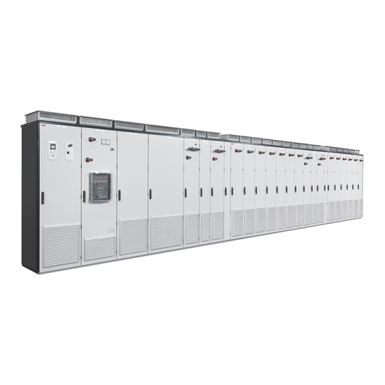
- Page 1 — ABB INDUSTRIAL DRIVES ACS880-607 3-phase brake units Hardware manual...
- Page 3 ACS880-607 3-phase brake units Hardware manual Table of contents 3. Mechanical installation 5. Electrical installation 8. Start-up © 2019 ABB Oy. All Rights Reserved. 3AXD50000022034 Rev D EFFECTIVE: 2019-04-29...
-
Page 5: Table Of Contents
Table of contents 5 Table of contents 1 Introduction to the manual Contents of this chapter ................Applicability ..................Safety instructions ................Target audience ................... Related manuals .................. Categorization by frame size and option code ..........Use of component designations ..............Terms and abbreviations ................. - Page 6 6 Table of contents Minimizing electromagnetic interference ........... Maximum cable length ................ Placing the brake resistors ..............Selecting the resistor thermal switch cable ........... Protecting the system against thermal overload ..........Operation principle ................Protecting the system against short-circuits ..........5 Electrical installation Contents of this chapter ................
- Page 7 Table of contents 7 Warning and fault messages ..............7-segment display of the brake control unit ........... 10 Maintenance Contents of this chapter ................Reference to maintenance instructions ............Replacing brake chopper and brake resistor fuses – bottom exit ......Replacing brake chopper and brake resistor fuses –...
-
Page 9: Introduction To The Manual
Introduction to the manual 9 Introduction to the manual Contents of this chapter This chapter gives basic information on the manual. Applicability The manual is applicable to ACS880-607 3-phase brake units that form a part of an ACS880 multidrive system. Safety instructions Follow all safety instructions delivered with the drive. -
Page 10: Related Manuals
3AUA0000094606 Manuals for I/O extension modules, fieldbus adapters, safety options etc. You can find manuals on the Internet. See www.abb.com/drives/documents. For manuals not available in the document library, contact your local ABB representative. Categorization by frame size and option code Some descriptions, instructions, technical data and dimensional drawings which concern only certain brake units are marked with the symbol of the frame size such as 4×R8i. -
Page 11: Use Of Component Designations
Introduction to the manual 11 The instructions and technical data which concern only certain optional selections are marked with option codes (such as +E210). The options included in the drive can be identified from the option codes visible on the type designation label. Use of component designations Some device names in the manual include the item designation in brackets, for example [Q20], to make it possible to identify the components in the circuit diagrams of the drive. -
Page 13: Operation Principle And Hardware Description
Operation principle and hardware description 13 Operation principle and hardware description Contents of this chapter This chapter describes the operation principle and construction of the brake unit. Product overview ACS880-607 is an air-cooled cabinet-installed brake unit, which forms a part of an ACS880 multidrive system. - Page 14 14 Operation principle and hardware description t° AC supply Input (AC) fuses Supply unit DC bus Inverter DC fuses (with or without a DC switch/disconnector) Inverter units (in this example, one of the two units consists of two inverter modules connected in parallel) Brake chopper fuses Brake unit Brake resistors (user-defined or option +D151)
-
Page 15: Layout Drawings
Operation principle and hardware description 15 Layout drawings The figure below shows the components of the brake chopper cubicle with bottom entry and exit of cables and shrouds removed. Control panel (option +J400) Cable entries for brake resistor and control cables Drive monitoring display (option +J401) Terminals for brake resistor cable connection... - Page 16 16 Operation principle and hardware description The figure below shows the components of the brake chopper cubicle with bottom entry and exit of cables and shrouds removed – option +F286 included. Control panel (option +J400) Brake resistor fuses DC switch/disconnector handle (part of option BCU-x2 control unit +F286) Charging circuit switch fuse handle (part of op-...
- Page 17 Operation principle and hardware description 17 The figure below shows the components of the brake chopper cubicles with top entry and exit of cables and shrouds removed. Control panel (option +J400) Terminals for brake resistor cable connection Drive monitoring display (option +J401) Brake resistor fuses Brake chopper fuses Cabinet fans...
-
Page 18: Frame R8I Layout
18 Operation principle and hardware description Frame R8i layout This figure shows the layout of the R8i module. R8i module, front R8i module, back DC busbars Handle LEDs and fiber optic connectors Fan (standard speed-controlled fan shown; a direct-on-line fan is available as option +C188) Quick connector (three phases). -
Page 19: Brake Chopper Module Connectors
Operation principle and hardware description 19 Brake chopper module connectors ■ Connectors X50…X53 Connector X50 Not in use. 115/230 V AC (50/60 Hz) input for optional heating element (+C183). Not in use in brake chopper modules. Not in use. 115/230 V AC 50 Hz input for internal power supply (BDPS) (115 V AC 60 Hz with option +G304). -
Page 20: Fibre Optic Connectors
20 Operation principle and hardware description ■ Fibre optic connectors Name Description BSFC BSFC Charging controller connection (option +F286). BFPS BFPS Fan control connection (to fan control box). Control unit connection. Overview of power and control connections The diagram below shows the power and control connections of the brake unit consisting of one 3-phase brake chopper module. -
Page 21: Brake Unit Control Devices
Operation principle and hardware description 21 Brake chopper cubicle DC switch/disconnector with charging circuit (option +F286) Control unit Brake chopper module Brake resistors (user-defined or option +D151) Brake unit control devices Each brake chopper module employs a dedicated control unit (BCU) that contains the BCON board with basic I/Os and slots for optional modules. -
Page 22: Overview Of The Control Connections Of The Bcu Control Unit
22 Operation principle and hardware description ■ Overview of the control connections of the BCU control unit The diagram shows the control connections and interfaces of the BCU control unit. Analog and digital I/O extension modules and Control panel. fieldbus communication modules can be inserted into slots 1, 2 and 3. -
Page 23: Control By Pc Tools
Operation principle and hardware description 23 ■ Control by PC tools There is a USB connector on the front of the panel that can be used to connect a PC to the drive. ■ Fieldbus control The unit can be controlled through a fieldbus interface if it is equipped with an optional fieldbus adapter, and when the control program has been configured for fieldbus control by parameters. -
Page 24: Brake Unit Type Designation Label
24 Operation principle and hardware description ■ Brake unit type designation label An example label of the brake unit is shown below. Type designation. Manufacturer’s address. Frame size. Cooling method. Degree of protection. Maximum input voltage (UL/CSA). Ratings. Valid markings. Serial number. -
Page 25: Brake Unit Type Designation Key
Operation principle and hardware description 25 Type designation. Frame size. Degree of protection; additional UL/CSA specifications. Ratings. The labels show ratings for inverter module (INVERTER), IGBT supply module (LINE CONVERT- ER), brake chopper module (BRAKE CHOPPER), regenerative rectifier module (REGENERATIVE RECTIFIER) and DC/DC converter module (DC/DC CONVERTER). - Page 26 26 Operation principle and hardware description CODE DESCRIPTION Voltage range 513…566 V DC. This is indicated in the type designation label as typical input voltage level 566 V DC. 513…707 V DC. This is indicated in the type designation label as typical input voltage levels 566 / 679 / 707 V DC.
- Page 27 Operation principle and hardware description 27 CODE DESCRIPTION G304 115 V control voltage for relays Materials G314 DC busbar material aluminum G315 DC busbar material tin plated copper G320 230 V AC control transformer G330 Halogen-free wiring and materials Cabling H352 Brake resistor cables through the bottom of the cabinet H353...
-
Page 28: Brake Chopper Module Type Designation Key
28 Operation principle and hardware description CODE DESCRIPTION K470 FEPL-01 Ethernet POWERLINK adapter module K473 FENA-11 Ethernet/IP™, Modbus/TCP and PROFINET adapter module K475 FENA-21 high performance Ethernet/IP™, Modbus/TCP and PROFINET adapter module K480 Ethernet switch with optical link for PC tool and control network Documentation Note: English-language manuals are included if a translation in the specified language is not available. - Page 29 Operation principle and hardware description 29 CODE DESCRIPTION 709…976 V DC. This is indicated in the type designation label as typical input voltage levels 742 / 849 / 976 (849 UL, CSA) V DC. Option codes (plus codes) Construction C132 Marine type approval C183 Module heater...
-
Page 31: Mechanical Installation
Mechanical installation 31 Mechanical installation Contents of this chapter This chapter describes the mechanical installation of the brake units. Brake units The ACS880 multidrive - the brake unit as one part of the complete drive - is transported in sections. See ACS880 multidrive cabinets mechanical installation instructions (3AUA0000101764 [English]). -
Page 33: Guidelines For Planning The Electrical Installation
The installation must always be designed and made according to applicable local laws and regulations. ABB does not assume any liability whatsoever for any installation which breaches the local laws and/or other regulations. Furthermore, if the recommendations given by ABB are not followed, the drive may experience problems that the warranty does not cover. -
Page 34: Selecting And Routing The Brake Resistor Cables
34 Guidelines for planning the electrical installation • The resistance (R) of the brake resistor assembly must be equal to or above the value specified. Never use resistance values below the specified value. • The resistor must withstand the specified brake cycles. •... -
Page 35: Selecting The Resistor Thermal Switch Cable
Guidelines for planning the electrical installation 35 WARNING! The materials near the brake resistor must be non-flammable. The surface temperature of the resistor is high. Air flowing from the resistor is of hundreds of degrees Celsius. If the exhaust vents are connected to a ventilation system, make sure that the material withstands high temperatures. -
Page 37: Electrical Installation
Electrical installation 37 Electrical installation Contents of this chapter This chapter contains instructions on wiring the brake units. WARNING! Obey the safety instructions of the drive. If you ignore them, injury or death, or damage to the equipment can occur. If you are not a qualified electrician, do not do installation or maintenance work. -
Page 38: Electrical Safety Precautions
38 Electrical installation Electrical safety precautions These electrical safety precautions are for all personnel who do work on the drive, motor cable or motor. WARNING! Obey these instructions. If you ignore them, injury or death, or damage to the equipment can occur. If you are not a qualified electrician, do not do installation or maintenance work. -
Page 39: General Notes
Electrical installation 39 General notes ■ Static electricity WARNING! Use a grounding wrist band when you handle printed circuit boards. Do not touch the boards unnecessarily. The boards contain components sensitive to electrostatic discharge. ■ Optical components WARNING! Obey these instructions. If you ignore them, damage to the equipment can occur. •... -
Page 40: Connecting The Brake Resistor Cables And Thermal Switch
Connection diagram This diagram shows the brake resistor cable connections and an example connection of the thermal switches. The diagram also shows the internal connections of the brake unit done by ABB. Brake chopper cubicle DC switch/disconnector including charging circuit (+F286) -
Page 41: Connection Procedure Of The Resistor Cables
Electrical installation 41 ■ Connection procedure of the resistor cables WARNING! Obey the safety instructions of the drive. If you ignore them, injury or death, or damage to the equipment can occur. If you are not a qualified electrician, do not do installation or maintenance work. 1. - Page 42 42 Electrical installation If the outer surface of the shield is non-conductive, turn the shield inside out and wrap copper tape around the cable to keep the shielding continuous. Do not cut the grounding wire (if any). Stripped cable Conductive surface of the shield exposed Stripped part covered with copper foil Cable shield Copper foil...
-
Page 43: Connecting A Pc
Electrical installation 43 8. At the other end of the cables, leave the shields unconnected or ground them via a capacitor (eg. 3.3 nF / 630 V). WARNING! IEC 60664 and IEC 61800-5-1 require double or reinforced insulation between resistor live parts and the sensor. If the assembly does not fulfill the requirement, the I/O terminals on the control unit must be protected against contact and must not be connected to other equipment, or the temperature sensor must be isolated from the I/O terminals, for example, with a suitable relay. -
Page 45: Control Units Of The Drive
Control units of the drive 45 Control units of the drive Contents of this chapter This chapter • describes the connections of the control unit, • contains the specifications of the inputs and outputs of the control unit. General The brake unit is controlled by a BCU-x2 control unit. The BCU-x2 consists of a BCON-12 control board (and a BIOC-01 I/O connector board and power supply board) built in a metal housing. -
Page 46: Bcu-X2 Control Unit Layout And Connections
46 Control units of the drive BCU-x2 control unit layout and connections Description I/O terminals (see following diagram) SLOT 1 I/O extension, encoder interface or fieldbus adapter module connection. (This is the sole location for an FDPI-02 diagnostics and panel interface.) SLOT 2 I/O extension, encoder interface or fieldbus adapter module connection... - Page 47 Control units of the drive 47 Description Analog inputs Analog outputs Digital inputs, Digital input interlock (DIIL) XRO3 XD24 XPOW XDIO Digital input/outputs XD2D Drive-to-drive link XRO2 XDIO XD24 +24 V output (for digital inputs) XETH Ethernet port – Not in use XRO1 XPOW External power input...
-
Page 48: Default I/O Diagram Of The Brake Control Unit
48 Control units of the drive Default I/O diagram of the brake control unit The diagram below shows the default I/O connections on the brake control unit, and describes the use of the signals/connections. Under normal circumstances, the factory-made wiring should not be changed. -
Page 49: External Power Supply For The Control Unit (Xpow)
(nominal impedance 100 to 165 ohm, for example Belden 9842) for the wiring. For best immunity, ABB recommends high quality cable. Keep the cable as short as possible. Avoid unnecessary loops and parallel runs near power cables such as motor cables. -
Page 50: Safe Torque Off (Xsto, Xsto Out)
The BCU-x2 has an on-board data logger that collects real-time data from the power modules to help fault tracing and analysis. The data is stored onto the SDHC memory card inserted into the SD CARD slot and can be analyzed by ABB service personnel. -
Page 51: Connector Data
Power supply Connector pitch 5 mm, wire size 2.5 mm (XPOW) 24 V (±10%) DC, 2 A Control units of the drive 51 External power input. Two supplies can be connected for redundancy. Relay outputs RO1…RO3 Connector data Connector pitch 5 mm, wire size 2.5 mm (XRO1…XRO3) 250 V AC / 30 V DC, 2 A Power supply (XPOW) - Page 52 52 Control units of the drive Analog inputs AI1 and AI2 Connector pitch 5 mm, wire size 2.5 mm (XAI:4 … XAI:7). Current input: –20…20 mA, R = 100 ohm Current/voltage input mode selection by Voltage input: –10…10 V, R >...
-
Page 53: Bcu-X2 Ground Isolation Diagram
Control units of the drive 53 Control units of the drive 137 ■ BCU-x2 ground isolation diagram Ground isolation diagram XPOW +24VI +24VI +VREF -VREF AGND AI1+ Common mode voltage AI1- AI2+ between each AI input and AI2- AGND is +30 V AGND AGND XD2D... -
Page 55: Installation Checklist Of The Drive
Installation checklist of the drive 55 Installation checklist of the drive Contents of this chapter This chapter contains a checklist of the mechanical and electrical installation of the drive. Checklist Examine the mechanical and electrical installation of the drive before start-up. Go through the checklist together with another person. - Page 56 56 Installation checklist of the drive Make sure that … The input power cable has been connected to the appropriate terminals, the phase order is right, and the terminals have been tightened. (Pull on the conductors to check.) There is an adequately sized protective earth (ground) conductor between the motor and the drive, and the conductor has been connected to appropriate terminal, and the terminal has been tightened.
-
Page 57: Start-Up
Start-up 57 Start-up Contents of this chapter This chapter contains the start-up procedure of the brake unit. The symbols in brackets, for example (Q1), refer to the item designations used in the circuit diagrams. If a task is valid only for a certain option device or feature, the option code is given in brackets, for example, (option +F286). - Page 58 58 Start-up Tasks Make sure that the supply unit of the drive system has been started up according to the instruc- tions in its hardware manual. Make sure that the inverter units of the drive system have been started up according to the in- structions in their hardware manual.
-
Page 59: Fault Tracing
Check sensor. Replace faulty sensor. Short circuit in resistor or power cables. Check power cables and resistor. Chopper control board failure. Chopper Contact local ABB representative. damaged; it is not able to disconnect resistor from intermediate circuit. Chopper does not function. -
Page 60: Leds
60 Fault tracing Fault indication/Fault Cause What to do Chopper starts to function at Chopper voltage setting too low. Check voltage setting. too low a DC voltage. Inverter trips on fault 3210 DC Chopper voltage setting too high. Check voltage setting. link overvoltage. -
Page 61: R8I Module Leds
Fault tracing 61 ■ R8i module LEDs Frame R8i modules have three LEDs. For their indications, see the following table. Location Indication R8i module FAULT There is an active fault in the module. (continuous red) ENABLE / STO The module is ready for use. (continuous green) ENABLE / STO XSTO connectors are de-energized. -
Page 63: Maintenance
Maintenance 63 Maintenance Contents of this chapter This chapter refers to maintenance instructions of the brake unit. Reference to maintenance instructions See the ACS880-107 inverter units hardware manual (3AUA0000102519 [English]) for • preventive maintenance intervals of cooling fans and converter modules •... -
Page 64: Replacing Brake Chopper And Brake Resistor Fuses - Bottom Exit
64 Maintenance Replacing brake chopper and brake resistor fuses – bottom exit WARNING! Obey the safety instructions of the drive. If you ignore them, injury or death, or damage to the equipment can occur. If you are not a qualified electrician, do not do installation or maintenance work. 1. -
Page 65: Replacing Brake Chopper And Brake Resistor Fuses - Top Exit
Maintenance 65 Replacing brake chopper and brake resistor fuses – top exit WARNING! Obey the safety instructions of the drive. If you ignore them, injury or death, or damage to the equipment can occur. If you are not a qualified electrician, do not do installation or maintenance work. 1. - Page 66 66 Maintenance...
-
Page 67: Technical Data
Technical data 67 Technical data Contents of this chapter This chapter contains the technical data for the brake units. Ratings ACS880- Frame Resistor values Ratings with R 607-… size No overload use Cyclic load (1 min / 5 min) contmax A DC A DC A DC... - Page 68 68 Technical data ACS880- Frame Resistor values Ratings with R 607-… size No overload use Cyclic load (1 min / 5 min) contmax A DC A DC A DC A DC A DC (kVA) 3770-5 4×R8i 4685 1862 3770 2220 5994 2106 4820...
-
Page 69: Definitions
Technical data 69 ACS880- Frame Resistor values Ratings with R 607-… size No overload use Cyclic load (1 min / 5 min) contmax A DC A DC A DC A DC A DC (kVA) 3900-7 3×R8i 3514 1275 3900 1405 3746 1316 4160... -
Page 70: Derating
70 Technical data ■ Derating Temperature derating In the temperature range +40…50 °C (+104…122 °F), the rated output current is derated by 1% for every added 1 °C (1.8 °F). The output current can be calculated by multiplying the current given in the rating table by the derating factor (k): Altitude derating At altitudes from 1000 to 2000 m (3300 to 6561 ft) above sea level, the continuous output currents given above must be derated 1% for every 100 m (328 ft). -
Page 71: Type Equivalence Table
Technical data 71 (V AC) Input voltage U (DC) Output voltage U (0…U 3-phase symmetrical), ie, resistor (AC) connec- tion 513…566 V DC. 3 × 0…566 V DC This is indicated in the type designation la- This is indicated in the type designation la- bel as typical input voltage level 566 V DC. -
Page 72: Typical Resistor Cable Sizes
72 Technical data ACS880-607-... Brake module type* Basic module type Frame size 2600-7 ACS880-104-1170A-7 ACS880-104-0600A-7 2×R8i 3900-7 ACS880-104-1740A-7 ACS880-104-0600A-7 3×R8i 5200-7 ACS880-104-2300A-7 ACS880-104-0600A-7 4×R8i 6500-7 ACS880-104-2860A-7 ACS880-104-0600A-7 5×R8i * Type of brake module(s) to be installed into a user-defined cabinet. Typical resistor cable sizes This table gives copper cable types. -
Page 73: Maximum Cable Length
Technical data 73 ACS880-607-... Frame size Cable data rms dim Cable, T=70 °C Cable, T=90 °C 1730-7 2×R8i 2×(3×(2×(3×120+70))) 2×(3×(3×240+120)) 2600-7 2×R8i 1117 2×(3×(2×(3×240+120))) 2×(3×(2×(3×150+70))) 3900-7 3×R8i 1676 3×(3×(2×(3×240+120))) 3×(3×(2×(3×150+70))) 5200-7 4×R8i 2234 4×(3×(2×(3×240+120))) 4×(3×(2×(3×150+70))) 6500-7 5×R8i 2793 5×(3×(2×(3×240+120))) 5×(3×(2×(3×150+70))) ■... -
Page 74: Dimensions, Weights And Free Space Requirements
74 Technical data 1300-7 170M6548 1000 A; 1100 V 170M6546 800 A; 1250 V 1730-7 170M6544 630 A; 1250 V 170M6542 500 A; 1250 V 2600-7 170M6548 1000 A; 1100 V 170M6546 800 A; 1250 V 3900-7 170M6548 1000 A; 1100 V 170M6546 800 A;... -
Page 75: Losses, Cooling Data And Noise
Technical data 75 Height 1 Height of IP22 and IP42 units Height 2 Height of IP54 units Width 1 Standard width with bottom exit of cables Width 2 Standard width with top exit of cables Depth 1 Depth of standard units Depth 2 Depth of units with air inlet through bottom Weight 1... -
Page 76: Resistor Connection
Installation site altitude 0…2000 m (0…6562 ft) above sea level. For alti- tudes over 2000 m, contact ABB. Output derated above 1000 m (3281 ft). Air temperature 0 … +40 °C -40 to +70 °C (- -40 to +70 °C (-... - Page 77 Technical data 77 Operation Storage Transportation installed for stationary in the protective package in the protective package Relative humidity Max. 95% Max. 95% Max. 95% No condensation allowed. Maximum allowed relative humidity is 60% in the presence of corrosive gases. Contamination IEC/EN 60721-3-3:2002: IEC 60721-3-1:1997...
-
Page 78: Materials
IEC 62635 guidelines. To aid recycling, plastic parts are marked with an appropriate identification code. Contact your local ABB distributor for further information on environmental aspects and recycling instructions for professional recyclers. End of life treatment must follow international and local regulations. -
Page 79: Tightening Torques
Technical data 79 Tightening torques Unless a tightening torque is specified in the text, the following torques can be used. ■ Electrical connections Size Torque Note 0.5 N·m (4.4 lbf·in) Strength class 4.6...8.8 1 N·m (9 lbf·in) Strength class 4.6...8.8 4 N·m (35 lbf·in) Strength class 8.8 9 N·m (6.6 lbf·ft) -
Page 80: Cybersecurity Disclaimer
ABB and its affiliates are not liable for damages and/or losses related to such security breaches, any unauthorized... -
Page 81: Dimension Drawings
Dimension drawings 81 Dimension drawings Contents of this chapter This chapter contains example dimension drawings for the brake units. -
Page 82: Dimension Drawing - Bottom Exit
82 Dimension drawings Dimension drawing – bottom exit... - Page 83 Dimension drawings 83...
-
Page 84: Dimension Drawing - Top Exit
84 Dimension drawings Dimension drawing – top exit... - Page 85 Dimension drawings 85...
-
Page 87: Further Information
Product and service inquiries Address any inquiries about the product to your local ABB representative, quoting the type designation and serial number of the unit in question. A listing of ABB sales, support and service contacts can be found by navigating to www.abb.com/searchchannels. - Page 88 3AXD50000022034D © 2019 ABB Oy. All Rights Reserved. Specifications subject to change without notice.