Table of Contents
Advertisement
Quick Links
Advertisement
Table of Contents

Related Manuals for Siemens YASKAWA 840DI


Summary of Contents for Siemens YASKAWA 840DI
- Page 1 Yaskawa Siemens CNC Series Maintenance Manual MANUAL No. NCSIE-SP02-10B...
- Page 2 Controls Corp." in this manual should therefore be understood as "Siemens Japan K.K." This manual is intended for both of Yaskawa Siemens 840DI and Yaskawa Siemens 830DI. In this manual, the functional differences of these two models are not taken into account in its description, thus please refer to the catalog (MANUAL No.: NCKAE-PS41-01) for...
-
Page 3: Safety-Related Symbol Marks
Safety-related symbol marks Safety-related symbol marks The following symbol marks are used in this manual to draw special attention to safety information. The information next to these symbol marks is important for safety and thus must always be followed. Indicates activities that could result in a dangerous condition, including death and WARNING serious injury, if done wrongly. -
Page 4: Icon Display
Explains terms that are difficult to understand or used with no preliminary explanation. TERMS Copyright 2006 Yaskawa Siemens Numerical Controls Corp. All or any part of this document may not be carried or copied without written permission from the company. -
Page 5: Table Of Contents
Contents Contents Safety-related symbol marks - - - - - - - - - - - - - - - - - - - - - - - - - - - - - - - iii Icon display - - - - - - - - - - - - - - - - - - - - - - - - - - - - - - - - - - - - - - - - - - - iv Contents - - - - - - - - - - - - - - - - - - - - - - - - - - - - - - - - - - - - - - - - - - - - - v Outline of the manual - - - - - - - - - - - - - - - - - - - - - - - - - - - - - - - - - - - vii Trade marks - - - - - - - - - - - - - - - - - - - - - - - - - - - - - - - - - - - - - - - - - vii... -
Page 6: Contents
Contents 2.4 Check of battery- - - - - - - - - - - - - - - - - - - - - - - - - - - - - - - 2-10 2.4.1 Battery for SRAM memory in CNC- - - - - - - - - - - - - - - - - - - - - - - - - 2-10 2.4.2 Battery for calendar function - - - - - - - - - - - - - - - - - - - - - - - - - - - - - 2-11 2.4.3 Battery for 24V power supply to CNC unit - - - - - - - - - - - - - - - - - - - 2-12 2.4.4 Battery for absolute encoder - - - - - - - - - - - - - - - - - - - - - - - - - - - - - 2-13... -
Page 7: Outline Of The Manual
For maintenance of the entire machine, refer to the manuals published by the machine tool builder. This manual is intended for both of Yaskawa Siemens 840DI and Yaskawa Siemens 830DI. In this manual, the functional differences of these two models are not taken into account in its description, thus please refer to the catalog (MANUAL No.:... -
Page 8: Related Manuals
Read all related manuals to grasp the specifications. Manual Name Manual Number Yaskawa Siemens CNC series (Catalog) NCKAE-PS41-01 Yaskawa Siemens CNC series Operating Manual for Standard HMI NCSIE-SP02-24 Yaskawa Siemens CNC series Operating Manual for Machining Center NCSIE-SP02-25 Yaskawa Siemens CNC series Programming Manual for Machining Center... -
Page 9: How To Use The Manual
Target readers This manual is intended for use by personnel in charge of maintenance of machine control panel and operator panel of machine tools controlled by the Yaskawa Siemens CNC series. The name of Drive Units In this manual, the following terms are used fundamentally. -
Page 10: Safety Precautions
Safety precautions Safety precautions Listed below are important safety precautions that you must always follow when using the product. Read and fully understand this manual and other related manuals before attempting to install, operate, maintain, or service the product. The safety precautions and the knowledge of the product are indispensable for the safety of yourself and the product. - Page 11 Safety precautions MANDATORY • Store the product in an indoor clean place satisfying the environmental requirements. Otherwise damage could result. • Ambient temperature : -20 to +60 °C • Relative humidity : 10 to 90 % • Altitude : 1000 m or lower Installation CAUTION •...
- Page 12 Safety precautions CAUTION • Observe the following when installing the units. Poorly installed units could result in damage or malfunction: • The Drive Units must be fixed upright using screws or bolts. • The Drive Units must be provided with enough space over and under them to allow them to effectively dissipate their heat.
- Page 13 Safety precautions CAUTION • Never apply an AC three-phase power to the U, V, and W output terminals on a Drive Unit powering a motor. Otherwise the Drive Unit would be damaged. • The capacity and wiring size of customer’s power supply must be so selected as to satisfy the specific operating conditions and required capacity.
- Page 14 Safety precautions MANDATORY • The grounding wire from each unit must be connected to the enclosure or the grounding plate directly. Example grounding wiring Drive Unit 200 VAC Enclosure Operating relay sequence Single-point grounding Ground resistance or less • Wires for grounding must be in accordance with applicable electrical installation regulations and the internal wiring rules.
- Page 15 Safety precautions Operating WARNING • Do not touch live units or terminals. Otherwise electric shock or malfunction could result. • Do not touch any current-carrying parts even if you have shut off power to them, until at least 5 minutes have passed (to let any residual charge go out). Otherwise electric shock or malfunction could result.
- Page 16 Safety precautions CAUTION • Ensure that the environmental requirements are fully met. A fire, electric shock, or malfunction could result if the product were operated in excessively hot, humid, dusty, corrosive, vibration-, or shock-ridden conditions. The environmental requirements are these: •...
- Page 17 Safety precautions MANDATORY • When switching on the main power, ensure that at least 2 seconds have elapsed after the last switching-off operation. Otherwise malfunction could result. PROHIBITED • Never attempt to disassemble or modify the units or devices in the control panels. Otherwise a fire, damage, or malfunction could result.
- Page 18 • If the nameplate on the products is defaced or damaged, order a new one from your dealer or the nearest sales office indicated on the back cover of this manual. • Yaskawa Siemens Numerical Controls would not guarantee the quality of the product modified by the customer. Yaskawa Siemens Numerical Controls is not responsible for any injury or damage due to the product modified by the customer.
-
Page 19: Warning Labels
Warning labels Warning labels Warning labels are attached to the product to draw special attention. Always follow the instructions. The locations and meanings of the warning labels are as follows: Warning label 1 WARNING Risk of electric shock 危険 WARNING けが感電のおそれがあります,... -
Page 20: Hardware
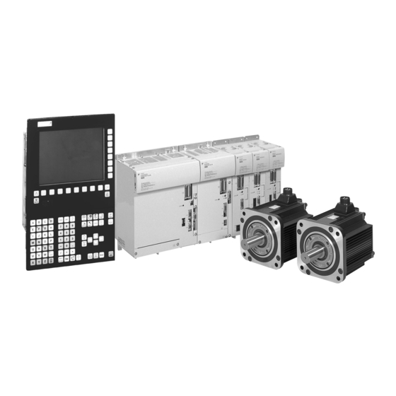
Hardware This chapter explains the hardware of Yaskawa Siemens CNC series. 1.1 General connections between equipments - - - - - - - - - - - - - 1-2 1.2 Outside appearance - - - - - - - - - - - - - - - - - - - - - - - - - - - - - 1-4 1.2.1 Operator panel - - - - - - - - - - - - - - - - - - - - - - - - - - - - - - - - - - - - - - - 1-4... -
Page 21: General Connections Between Equipments
1.1 General connections between equipments General connections between equipments The example connections for Yaskawa Siemens 840DI system are described in the figure below. Termination connector Yaskawa Siemens 840DI CN5B Operator panel CNC unit PCU50 POWER ( Color LCD) CN28 PG (serial) - Page 22 Notes on above figure INFO (1) Equipments The figure shows an example of connections for Yaskawa Siemens 840DI. Please refer to the documents published by machine tool builder for actually connected or available equipments on your machine. (2) CNC power supply DC UPS module and battery module for UPS may not be installed on your machine tool builder.
-
Page 23: Outside Appearance
1.2 Outside appearance Outside appearance The figures are described roughly in the following subsections. Therefore, its image may be different from the actual unit. 1.2.1 Operator panel The operator panel has CNC unit on the rear side and they are treated as a unit. Table 1.1 Operator panel Type/ Specifications/... - Page 24 1.2 Outside appearance Bottom view DC UPS module (PROFIBUS-DP) (MPI) (MPI/DP) X101 X111 or X102 Backup battery for UPS 24VDC power supply COM1 COM2 PS/2 Mouse Ethernet MPI/DP LPT1 PS/2 Keyboard X121 (Handwheel, Emergency stop, UPS I/F) PC card drive Top view Connector for external floppy disk drive RESET...
-
Page 25: Drive Unit
Servo Unit SGDK-xxxxxxAEA x: Depending on capacity. CHARGE CHARGE (three axes) 1.2.4 ET200M remote I/O system Table 1.4 ET200M remote I/O system Specifications/ Type/ SIEMENS General name Order number Remarks Interface 6ES7153-1AA03- module 0XB0 Input module 6ES7321-xxxxx-xxxx x: Depending on specification. -
Page 26: Board Type I/O Module
1.2 Outside appearance 1.2.5 Board type I/O module Table 1.5 Board type I/O module Type/ Specifications/ General name Order number Remarks Machine control 6FC5611-0CA01-0AA0 72 inputs panel I/O /48 outputs 1.2.6 External memory device Table 1.6 External memory device Type/ Specifications/ General name Order number... -
Page 27: Power Supply For Cnc Unit
1.2 Outside appearance 1.2.7 Power supply for CNC unit Table 1.7 Power supply for CNC unit o.k. Type/ Specifications/ Alarm Bat> DC-USV-Modul 15 General name X2.1 Order number Remarks +0.5V X2.2 o.k. X2.3 +0.5V Alarm +0.2V X2.4 Power supply 6EP1334-2BA0x 24VDC, 10A +0.2V +0.1V... -
Page 28: Brake Power Supply Unit
1.2 Outside appearance 1.2.9 Brake power supply unit Table 1.9 Brake power supply unit Type/ Specifications/ General name Order number Remarks Brake power OPR-109A 200VAC supply unit 1.2.10 Serial converter Table 1.10 Serial converter Type/ Specifications/ General name Order number Remarks Serial JZDP-B001-000... -
Page 29: Check And Maintenance
This chapter explains the check and maintenance to keep the basic performance of Yaskawa Siemens CNC series. 2.1 Check of control panel - - - - - - - - - - - - - - - - - - - - - - - - - - - 2-2 2.1.1 Check of securely closing door (daily) - - - - - - - - - - - - - - - - - - - - - - - 2-2... -
Page 30: Check Of Control Panel
CNC system are left powered. Otherwise electric shock or damage could result. For the long and safe use of Yaskawa Siemens CNC series, never fail to execute the daily maintenance work described below. Be sure to shut down the power supply to the CNC system before daily maintenance except for inspections that can be performed with the power supply for the CNC system turned on, such as inspection for external contamination, vibration, or abnormal sound. -
Page 31: Check Of Servomotor And Servo Unit
2.2 Check of Servomotor and Servo Unit Check of Servomotor and Servo Unit 2.2.1 Check of Servomotor The following table shows how to conduct a daily check and maintenance of the Servomotor. Since AC Servomotors are brushless, you need not conduct any other checks than a brief daily check. -
Page 32: Check Of Servo Unit
2.2 Check of Servomotor and Servo Unit 2.2.2 Check of Servo Unit The following table summarizes how to check the Servo Unit. You need not conduct a daily check; however, conduct a check once a year at least. Table 2.2 Check of Servo Unit Check item Check timing Check method... -
Page 33: Check Of Spindle Motor, Inverter, And Converter
2.3 Check of Spindle Motor, Inverter, and Converter Check of Spindle Motor, Inverter, and Converter Conduct scheduled maintenance management so that the system may keep operating correctly in good conditions. WARNING • To check the converter, you must turn off the power and wait for 5 minutes before accessing inside ”... -
Page 34: Scheduled Maintenance
2.3 Check of Spindle Motor, Inverter, and Converter Table 2.4 Daily maintenance for Spindle Motor, Inverter, and Converter (cont’d) Check procedure Check object Criteria Corrective action Item Method Around the Sound from the Hearing or Shall be free from abnormal sound Replace the bearing. -
Page 35: Periodical Check
2.3 Check of Spindle Motor, Inverter, and Converter 2.3.4 Periodical check Referring to the following table, establish a maintenance schedule and conduct a periodical check. Check timing is mentioned for some items in the table; however, it is guide line. Determine appropriate timing that best fits your machine considering operating status and environment by increasing or decreasing the described value. - Page 36 2.3 Check of Spindle Motor, Inverter, and Converter Table 2.5 Periodical check (cont’d) Check procedure Check object Criteria Corrective action Item Method − − Motor coupling Repetitive run out Readjustment by status direct-coupled centering 1. Shaft Sunk key Viewing Scratch or deformation shall Replacement coupling not exist.
- Page 37 2.3 Check of Spindle Motor, Inverter, and Converter A guide line of parts replacement timing Inverter and Converter comprise a lot of parts that make possible for Inverter and Converter to achieve full functionality only when they work correctly. Some of them need to be replaced according to their operating status. These parts must be checked periodically and replaced depending on their service life to use Inverter and Converter without trouble for a long time.
-
Page 38: Check Of Battery
2.4 Check of battery Check of battery Yaskawa Siemens CNC series may be used with backup batteries for • SRAM in CNC unit, • calendar in CNC unit, • 24V power supply to CNC unit (Your machine may not have backup battery for 24V power supply to CNC.) and / or •... -
Page 39: Battery For Calendar Function
2.4 Check of battery Replacing battery WARNING • When carrying out maintenance work on this equipment, below warnings must be followed. • Maintenance may only be performed by qualified personnel. • The service intervals and the instructions for repair and replacement must be strictly followed. When operating electrical devices, certain parts of these devices are inevitably under hazardous voltage. -
Page 40: Battery For 24V Power Supply To Cnc Unit
2.4 Check of battery 2.4.3 Battery for 24V power supply to CNC unit The battery for 24V power supply to CNC unit may not be used in your machine. Please see INFO the document published by machine tool builder. Battery type 24V sealed lead-acid battery (secondary battery) Order number: 6EP1935-6MD31 (2.5Ah, 60 max.) -
Page 41: Battery For Absolute Encoder
2.4 Check of battery Replacing battery WARNING • When replacing battery module for UPS, following term must be taken in account. • Qualified personnel may only perform maintenance. • Before carrying out any maintenance and service work, the equipment must be disconnected from main power supply and the main power switch must be fixed on OFF position. - Page 42 2.4 Check of battery Criteria of replacing battery If the voltage of the absolute encoder battery decreases to 2.7V or less, the Servo Unit issues Battery warning (A.93)” and following message is displayed on Operator panel of CNC. “ 380500 Profibus-DP: fault on drive %1, code 147, value %3, time %4” “...
- Page 43 2.4 Check of battery • Old type Converter may not have battery cover. In this case, remove option cover fixed by 2-M4 INFO screws instead of battery cover in above procedure. ” • “Battery warning is automatically deselected after replacing battery. •...
-
Page 44: Replacing Fan Of Drive Unit
2.5 Replacing fan of Drive Unit Replacing fan of Drive Unit The fan of Drive Unit is mounted on upside of unit. The type of mounting fan is divided into two types as shown in the table below. The appearance of those types and the way of replacing fan can be referred in the following subsections. -
Page 45: Replacing In Fan Unit Type
2.5 Replacing fan of Drive Unit 2.5.2 Replacing in fan unit type Replace the Drive Unit fans as follows: 1. Open the up-down cover. 2. Unscrew the screw that holds the fan unit. The screw will remain loosely attached to the panel cover. -
Page 46: Replacing In Fan Cover Type
2.5 Replacing fan of Drive Unit 2.5.3 Replacing in fan cover type Replace the Drive Unit fans as follows: 1. Unscrew the screw that holds the fan cover. 2. Remove the fan. 3. Disengage the junction connector.* 4. Replace the fan with a new one. Pay attention to the orientation of the fan (air flow direction). -
Page 47: Diagnosis
Diagnosis This chapter explains the diagnosis method when an alarm or operation error occurs. 3.1 Diagnosis Operating Area - - - - - - - - - - - - - - - - - - - - - - - - - 3-2 3.1.1 Alarms/ Messages - - - - - - - - - - - - - - - - - - - - - - - - - - - - - - - - - - - - 3-2 3.1.2 Alarm help - - - - - - - - - - - - - - - - - - - - - - - - - - - - - - - - - - - - - - - - - - 3-2 3.1.3 Sorting alarm overview - - - - - - - - - - - - - - - - - - - - - - - - - - - - - - - - - 3-3... -
Page 48: Diagnosis Operating Area
3.1 Diagnosis Operating Area Diagnosis Operating Area 3.1.1 Alarms/ Messages The overview of alarms or messages, which are currently issued, can be displayed by pressing [Alarms] (HSK1) or [Messages] (HSK2) soft key in Diagnosis Operating Area. For further information about these screens, please refer to Operating Manual for “... -
Page 49: Sorting Alarm Overview
3.1 Diagnosis Operating Area 3.1.3 Sorting alarm overview Complete alarms that are currently issued in the channel including alarms for each axis are displayed in alarm overview screen. Therefore, multiple alarms with same number are often issued at the same time. In such case, pressing the vertical softkey [Sort] makes easier to take hold of the currently issued alarms because alarms with same number or same code number of drive alarm (380500) are gathered together and displayed on a line. -
Page 50: Errors Without Alarm Display And Troubleshooting
3.2 Errors without alarm display and troubleshooting Errors without alarm display and troubleshooting The table below shows the causes and their remedies for the malfunctions accompanied with no alarm generation. Before you check or take a remedy for what is described in the half-tone meshing column, you must turn off the power supply of Drive Unit. - Page 51 3.2 Errors without alarm display and troubleshooting Table 3.1 Errors without alarm display (cont’d) Malfunction Cause Check point Remedy Spindle Motor does Motor rated speed is set Check drive specific Set MD correctly. not rotate as specified incorrectly. machine data MD6500. speed.
- Page 52 3.2 Errors without alarm display and troubleshooting Table 3.1 Errors without alarm display (cont’d) Malfunction Cause Check point Remedy Spindle Motor and The earth ground of Check connection to Ground securely. Servomotor generates Motor or Drive Units is ground for motor and unusual noise or wrong.
-
Page 53: Important Messages
3.3 Important messages Important messages Warning message may be displayed as shown below if fatal error is detected or acknowledge is requested at replacement of whole memory data. The indications such as title bar, illustration of warning ( ) or warning message depends on INFO notification. - Page 54 3.3 Important messages Message Alarm: Old backup of user data loaded into MCI card. The user data were saved on 07.07.2000 10:30. Meaning This message may be indicated at first power on after replacement of MCI board (should be done our service). It may be displayed at first power on after extracting of Ghost data on rare occasions.
- Page 55 3.3 Important messages Message HMI-embedded-WIN32 Exception Handler (in title bar) Sorry, but HMI-embedded-WIN32 has caused an exception in task 27 Function at 00411eb6 with code 00083. Exception has occurred at CS=1b; EIP=0040 C41bEAX=0114f4b4 EAX=01100040 ECX=0114f57C EDX=000000b8 EDI=0110002c ESI=15133C01 FLAGS=00010202 ESP=00638e3c EBP=01638e68 SS=0023 DS=0023 ES=0023 FS=0038 GS=0000 •...
-
Page 56: Backup Of Data
Backup of Data CNC contains data and programs required for processing, such as tool information and part programs, and memory for storing programs and data required for system operation. Some of the data written to the memory changes with processing and procedures. -
Page 57: Data Backup Procedure
4.1 Data backup procedure Data backup procedure Yaskawa Siemens CNC series has Data in/out screens. Various data of CNC can be backed up on these screens. This page describes the outline of these screen. For further operation of these screens, please refer to Operating Manual for Machining Center”... -
Page 58: Data Type
4.2 Data type Data type Main folders of data folders displayed in [Manage data] screen are listed in the following table. Table 4.1 Main data folder General user Display name Stored area Contents MTB* user company NC active data CNC memory Various data stored in CNC memory. -
Page 59: Monitoring
Monitoring This chapter explains how to monitor the system operating status. 5.1 Monitor of Drive Unit - - - - - - - - - - - - - - - - - - - - - - - - - - - - - 5-2 5.1.1 Monitor cable - - - - - - - - - - - - - - - - - - - - - - - - - - - - - - - - - - - - - - - - 5-2 5.1.2 Data selection of Servo Unit - - - - - - - - - - - - - - - - - - - - - - - - - - - - - - 5-3 5.1.3 Data selection of Inverter - - - - - - - - - - - - - - - - - - - - - - - - - - - - - - - - 5-5... -
Page 60: Monitor Of Drive Unit
5.1 Monitor of Drive Unit Monitor of Drive Unit You can monitor various signals by using analog voltage. 5.1.1 Monitor cable To monitor analog monitor signals, use a dedicated monitor cable (DE9404559) connected to the CN6 (or CN16/CN26/CN36) of Servo Unit and Inverter as shown below. YASKAWA SERVOPACK SGDK-50AEA... -
Page 61: Data Selection Of Servo Unit
5.1 Monitor of Drive Unit Socket DF11-4DS-2C (Hirose Electric Co.) Contact DF11-2428SCF (Hirose Electric Co.) Pin No. White Black Black Dedicated monitor cable 5.1.2 Data selection of Servo Unit MD3003 can be used to specify the monitoring data of Servo Unit that is output as analog signal. - Page 62 5.1 Monitor of Drive Unit Monitor data can be set as follows: Table 5.3 MD3003 Monitor Data Selection Setting for 1st/3rd Meaning digit of MD3003 Monitor signal Observation gain Motor speed 1V/1000 min Speed setpoint 1V/1000 min 1V/100% Rated torque Torque setpoint 0.05V/input increment Position deviation...
-
Page 63: Data Selection Of Inverter
5.1 Monitor of Drive Unit 5.1.3 Data selection of Inverter Following machine data can be used to specify the monitoring data of Inverter that is output as analog signal. Table 5.5 Machine data for analog monitor of Inverter MD number Meaning Default Min. -
Page 64: Interface Signal Monitoring
5.2 Interface signal monitoring Interface signal monitoring Digital signals, bit memories, data blocks, timers or counters programmed in logic sequence can be monitored by pressing [PLC status] soft key in Maintenance operating area (for machining center system) or Diagnostic operating area (for turning/laser system). For further information of this screen, please refer to Operating Manual for Machining Center”... - Page 65 PHONE +81-3-3493-7411 FAX +81-3-3493-7422 PHONE +81-3-5423-7359 FAX +81-3-5423-7438 Siemens Japan K.K. http://www.siemens.co.jp Published in Japan 02-06 NCSIE-ZZ Published in Japan February 2012 06-4 11-9-13 02- WSC02, 02-WSC09 © Siemens Japan K.K. All rights reserved. © 2006-2012 Siemens Japan K.K. All rights reserved.