ABB REF 54 Series Technical Reference Manual, General
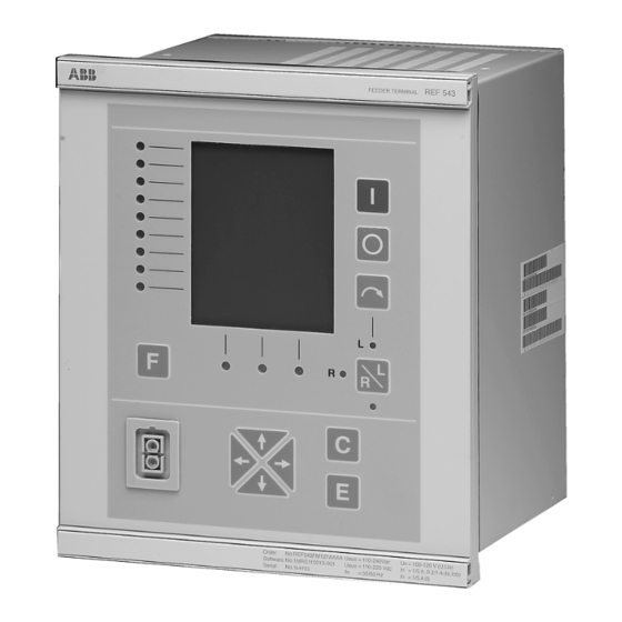
Feeder terminal
Hide thumbs
Also See for REF 54 Series:
- Technical reference manual (118 pages) ,
- Operator's manual (36 pages) ,
- Operator's manual (36 pages)
Table of Contents
Advertisement
Quick Links
Advertisement
Table of Contents

Related Manuals for ABB REF 54 Series


Summary of Contents for ABB REF 54 Series
- Page 1 Feeder Terminal REF 54_ Technical Reference Manual, General...
-
Page 3: Table Of Contents
5.1.2. Configuration ..............28 5.1.2.1. Feeder terminal configuration ......28 5.1.2.2. MIMIC configuration ...........29 5.1.2.3. LON network configuration .........31 5.1.2.4. DNP 3.0 and Modbus configuration ....31 5.1.2.5. Rated frequency ..........31 5.1.3. Parameters and events ............32 © Copyright 2005 ABB Oy, Distribution Automation, Vaasa, FINLAND... - Page 4 REF 54_ Feeder Terminal 1MRS750527-MUM Technical Reference Manual, General 5.1.4. Parameterization ............. 32 5.1.4.1. Local parameterization ........32 5.1.4.2. External parameterization ........32 5.1.4.3. Storing of parameters and recorded data ..33 5.1.5. Auxiliary voltage .............. 34 5.1.5.1. Power supply versions ........34 5.1.5.2.
- Page 5 REF 54_ 1MRS750527-MUM Feeder Terminal Technical Reference Manual, General 5.1.10.Analog outputs ..............61 5.1.10.1.Selection of analog output range .......61 5.1.10.2.Attributes of an analog output for feeder terminal configuration .........61 5.1.10.3.Analog output configuration example ....62 5.1.11.Trip circuit supervision .............63 5.1.11.1.Configuring the trip circuit supervision CMTCS_ 65 5.1.12.Self-supervision (IRF) ............65 5.1.12.1.Fault indication ...........66 5.1.12.2.Fault operation ...........66...
- Page 6 REF 54_ Feeder Terminal 1MRS750527-MUM Technical Reference Manual, General 6. Service ................... 101 7. Ordering Information ............103 7.1. Order number ................103 7.2. Hardware versions of REF 541, REF 543 and REF 545 ..104 7.3. Software configuration .............. 104 8.
-
Page 7: About This Manual
This document and parts thereof must not be reproduced or copied without written permission from ABB Oy, and the contents thereof must not be imparted to a third party nor used for any unauthorized purpose. -
Page 8: Use Of Symbols
1.6. Terminology The following is a list of terms that you should be familiar with. The list contains terms that are unique to ABB or have a usage or definition that is different from standard industry usage. Term Description... -
Page 9: Abbreviations
REF 54_ 1MRS750527-MUM Feeder Terminal Technical Reference Manual, General 1.7. Abbreviations Term Description Analog Input Circuit Breaker CBFP Circuit Breaker Failure Protection Central Processing Unit Current Transformer Digital Input Distributed Network Protocol Digital Output Electro-Magnetic Compatibility Ground GOOSE Generic Object Oriented Substation Event Human-Machine Interface HSPO High-Speed Power Output... -
Page 10: Related Documents
REF 54_ Feeder Terminal 1MRS750527-MUM Technical Reference Manual, General 1.8. Related documents Name of the manual MRS number General Manuals RE_ 5__ Installation Manual 1MRS750526-MUM RE_ 54_ Operator’s Manual 1MRS750500-MUM Protection & Control Terminals REF 54_, RET 54_, REM 54_, 1MRS750745-MUM REC 523 Configuration Guideline REF 54_, RET54_, REX 521 DNP 3.0 Communication Protocol,... -
Page 11: Safety Information
REF 54_ 1MRS750527-MUM Feeder Terminal Technical Reference Manual, General Safety information Dangerous voltages can occur on the connectors, even though the auxiliary voltage has been disconnected. National and local electrical safety regulations must always be followed. The device contains components which are sensitive to electrostatic discharge. -
Page 13: Introduction
3.1. General The REF 54_ feeder terminal is part of the ABB Distribution Automation system and extends the functionality and flexibility of the concept further. This is possible due to the modern technology applied both in hardware and software solutions. - Page 14 REF 54_ Feeder Terminal 1MRS750527-MUM Technical Reference Manual, General Table 3.2.-1 Hardware versions of REF 541 Order number HW modules Analog interface Sensor channels (current/ voltage) Current trafo 1/5 A Current trafo 0.2/1 A Voltage trafo 100 V Main processor boards CPU module Power supply boards PS1: 80...265 V AC/DC (High)
- Page 15 REF 54_ 1MRS750527-MUM Feeder Terminal Technical Reference Manual, General Table 3.2.-2 Hardware versions of REF 543 Order number HW modules Analog interface Sensor channels (current/voltage) Current trafo 1/5 A Current trafo 0.2/1 A Voltage trafo 100 V Main processor boards CPU module Power supply boards PS1: 80...265 V AC/DC (High)
- Page 16 REF 54_ Feeder Terminal 1MRS750527-MUM Technical Reference Manual, General Table 3.2.-3 Hardware versions of REF 545 Order number HW modules Analog interface Sensor channels (current/ voltage) Current trafo 1/5 A Current trafo 0.2/1 A Voltage trafo 100 V Main processor boards CPU module Power supply boards PS1: 80...265 V AC/DC (High)
-
Page 17: Instructions
REF 54_ 1MRS750527-MUM Feeder Terminal Technical Reference Manual, General Instructions 4.1. Application The REF 54_feeder terminals are designed to be used for the protection, control, measurement and supervision of medium voltage networks. They can be used with different kinds of switchgear including single busbar, double busbar and duplex systems. - Page 18 REF 54_ Feeder Terminal 1MRS750527-MUM Technical Reference Manual, General can be opened and closed over the remote control system. Position information and control signals are transmitted over the serial bus. Local control is also possible via the push-buttons on the front panel of the feeder terminal. The feeder terminal is designed to be used for the selective short-circuit and earth- fault protection.
-
Page 19: Requirements
REF 54_ 1MRS750527-MUM Feeder Terminal Technical Reference Manual, General In addition to protection, measurement, control and condition monitoring functions, the feeder terminals are provided with a large amount of PLC functions allowing several automation and sequence logic functions needed for substation automation to be integrated into one unit. -
Page 21: Technical Description
REF 54_ 1MRS750527-MUM Feeder Terminal Technical Reference Manual, General Technical Description 5.1. Functional description 5.1.1. Functions of the feeder terminal The functions of the REF 54_ feeder terminal are categorized as: • Protection functions • Measurement functions • Power quality functions •... - Page 22 REF 54_ Feeder Terminal 1MRS750527-MUM Technical Reference Manual, General Table 5.1.1.1-1 Protection functions available for REF 54_ (Continued) Function ANSI device no. IEC symbol Description 67-1 3I>--> Three-phase directional overcurrent protection, low-set stage DOC6Low 67-2 3I>>--> Three-phase directional overcurrent protection, high-set stage DOC6High 67-3 3I>>>-->...
-
Page 23: Measurement Functions
REF 54_ 1MRS750527-MUM Feeder Terminal Technical Reference Manual, General 5.1.1.2. Measurement functions Table 5.1.1.2-1 Measurement functions available for REF 54_ Function ANSI device no. IEC symbol Description General measurement 1 / analog input on RTD/analog module MEAI1 General measurement 2 / analog input on RTD/analog module MEAI2 General measurement 3 / analog input on RTD/analog module MEAI3... -
Page 24: Control Functions
REF 54_ Feeder Terminal 1MRS750527-MUM Technical Reference Manual, General 5.1.1.4. Control functions The control functions are used to indicate the position of switching devices, that is, circuit breakers and disconnectors, and to execute open and close commands for controllable switching devices in the switchgear. Furthermore, there are supplementary functions for control logic purposes, such as on/off switches, MIMIC alarm, LED control, numerical data for the MIMIC and logic controlled position selection. -
Page 25: Condition Monitoring Functions
REF 54_ 1MRS750527-MUM Feeder Terminal Technical Reference Manual, General Table 5.1.1.4-1 Control functions available for REF 54_ (Continued) Function ANSI device no. IEC symbol Description MMIDATA1 MMIDATA1 MMIDATA1 MIMIC data monitoring point 1 MMIDATA2 MMIDATA2 MMIDATA2 MIMIC data monitoring point 2 MMIDATA3 MMIDATA3 MMIDATA3... -
Page 26: General Functions
REF 54_ Feeder Terminal 1MRS750527-MUM Technical Reference Manual, General 5.1.1.7. General functions Table 5.1.1.7-1 General functions available for REF 54_ Function Description INDRESET Resetting of operation indicators, latched output signals, registers and waveforms,for example the disturbance recorder MMIWAKE Activation of HMI backlight SWGRP1 Switchgroup SWGRP1 SWGRP2... - Page 27 REF 54_ 1MRS750527-MUM Feeder Terminal Technical Reference Manual, General Table 5.1.1.8-1 Standard functions available for REF 54_ (Continued) Function Description Extensible comparison to greater INT_TO_* Type conversion from INT to REAL / DINT INT2BOOL Type conversion from INT input to BOOL outputs Extensible comparison to less or equal LIMIT Limitation...
-
Page 28: Configuration
REF 54_ Feeder Terminal 1MRS750527-MUM Technical Reference Manual, General 5.1.2. Configuration 5.1.2.1. Feeder terminal configuration The Relay Configuration Tool is based on the IEC 61131-3 standard. The standard defines the programming language used for the configuration. The programmable system of REF 54_ feeder terminals allows the output contacts to be operated in accordance with the state of the logic inputs and the outputs of the protection, control, measurement and condition monitoring functions. -
Page 29: Mimic Configuration
REF 54_ 1MRS750527-MUM Feeder Terminal Technical Reference Manual, General A050238 Fig. 5.1.2.1.-1 Example of a feeder terminal configuration with the Relay Configuration Tool 5.1.2.2. MIMIC configuration The control functions configured using the Relay Configuration Tool can be associated with position indicators that are part of the MIMIC configuration picture displayed on the graphic LCD of the HMI. - Page 30 REF 54_ Feeder Terminal 1MRS750527-MUM Technical Reference Manual, General A050239 Fig. 5.1.2.2.-1 MIMIC configuration with the Relay Mimic Editor The content of the alarm view is configured with the Relay Mimic Editor by defining the ON and OFF state texts (max 16 characters), see Fig. 5.1.2.2.-2 below. For defining the corresponding LED colors, refer to Section “Alarm LED indicators”...
-
Page 31: Lon Network Configuration
REF 54_ 1MRS750527-MUM Feeder Terminal Technical Reference Manual, General Interlocking LED texts can also be defined in the view illustrated above, but the interlocking LED colors cannot be changed. For the operation of the interlocking LED, refer to Section “Interlocking” on page 87. For more information about the use of the editor, refer to the Relay Mimic Editor manual (refer to Section “Related documents”... -
Page 32: Parameters And Events
REF 54_ Feeder Terminal 1MRS750527-MUM Technical Reference Manual, General 5.1.3. Parameters and events The function blocks and I/O cards include a large number of parameters and events. In addition, general parameters and events are provided, such as parameters for control and communication as well as events for testing and self-supervision. The function block specific parameters are listed in each function block description. -
Page 33: Storing Of Parameters And Recorded Data
REF 54_ 1MRS750527-MUM Feeder Terminal Technical Reference Manual, General A050241 Fig. 5.1.4.2.-1 Main dialog box of the Relay Setting Tool 5.1.4.3. Storing of parameters and recorded data When parameter values are changed, the new values take effect immediately. However, the new parameter values as well as the recorded data are saved in a non- volatile memory only after they have been stored via the parameter “Store”... -
Page 34: Auxiliary Voltage
REF 54_ Feeder Terminal 1MRS750527-MUM Technical Reference Manual, General 5.1.5. Auxiliary voltage For its operation the REF 54_ terminal, including the external display module, requires a secured auxiliary voltage supply. The feeder terminal’s internal power supply module forms the voltages required by the feeder terminal electronics. The power supply module is a galvanically isolated (flyback-type) DC/DC converter. -
Page 35: Low Auxiliary Voltage Indication
REF 54_ 1MRS750527-MUM Feeder Terminal Technical Reference Manual, General The external display module is only available together with a main unit equipped with the PS_/240 power supply module. The power supply version is specified by the first letter in the order number of REF 54_ (refer to Section “Ordering Information”... -
Page 36: Analog Channels
• 9 matching transformers: CT1, CT2, CT3, CT4, CT5, VT1, VT2, VT3, VT4 In addition to conventional matching transformers, current sensors and voltage dividers developed by ABB can be used in REF 54_ feeder terminals. The feeder terminal has 9 sensor inputs . - Page 37 REF 54_ 1MRS750527-MUM Feeder Terminal Technical Reference Manual, General A050184 Fig. 5.1.6.-1 Analog channels with 9 matching transformers and 9 sensors Depending on whether sensors are included or not, REF 54_ feeder terminals have 9 (without sensors) or 10 (with sensors) physical analog channels (see table below). The number of channels used depends on the feeder terminal configuration and the kind of matching transformers or sensor inputs used.
-
Page 38: Scaling The Rated Values Of The Protected Unit For Analog Channels
REF 54_ Feeder Terminal 1MRS750527-MUM Technical Reference Manual, General Table 5.1.6-1 Physical analog channels of the feeder terminals Measuring units Current Voltage Transformer Rogovski coil/- Voltage General Signal type (selectable Transformer (CT) (VT) sensor (RS) divider (VD) measure- alternatives) ment RS 1...10 VD 1...10 Gen. -
Page 39: Technical Data Of The Measuring Devices
REF 54_ 1MRS750527-MUM Feeder Terminal Technical Reference Manual, General The scaling factor is calculated channel by channel as follows: Scaling factor = I where Rated primary current of the measuring device (A) Rated primary current of the protected unit connected to the channel Example: Rated primary current of current trafo = 500 A: = 500 A... - Page 40 REF 54_ Feeder Terminal 1MRS750527-MUM Technical Reference Manual, General Values to be set for a voltage transformer: • Rated voltage of voltage input (same as the secondary rated voltage of the primary voltage transformer connected to the voltage input, 100 V, 110 V, 115 V, 120 V).
- Page 41 REF 54_ 1MRS750527-MUM Feeder Terminal Technical Reference Manual, General The measurement values stated by the manufacturer of the measuring device are used for calculating the correction parameters and factors according to the following formulas: Current transformers Amplitude error at current I Amplitude correction factor 1 = 1 / (1+ e/100) (e = error in per cent)
-
Page 42: Calculated Analog Channels
REF 54_ Feeder Terminal 1MRS750527-MUM Technical Reference Manual, General 5.1.6.3. Calculated analog channels The REF 54_ feeder terminal includes virtual channels to obtain phase-to-phase voltages, residual voltage and neutral current when sensors are used. Current sensors and voltage dividers are connected to the feeder terminal via coaxial cables. Therefore a phase-to-phase voltage connection, an open-delta connection of phase voltages or a residual connection of phase currents cannot be made. -
Page 43: Digital Inputs
REF 54_ 1MRS750527-MUM Feeder Terminal Technical Reference Manual, General 5.1.7. Digital inputs The REF 541, REF 543 and REF 545 feeder terminals differ from each other regarding the number of digital inputs available. The digital inputs of the REF 54_ feeder terminals are voltage-controlled and optically isolated. -
Page 44: Filter Time Of A Digital Input
REF 54_ Feeder Terminal 1MRS750527-MUM Technical Reference Manual, General Table 5.1.7-1 Digital inputs available for the REF 54_ (Continued) REF 541 REF 543 REF 545 BIO2_7_BI7 BIO2_7_BI8 BIO2_7_BI9 BIO2_7_BI10 Digital inputs / total 1) These digital inputs can be programmed as either digital inputs or pulse counters, refer to Section “Pulse counters”... -
Page 45: Inversion Of A Digital Input
REF 54_ 1MRS750527-MUM Feeder Terminal Technical Reference Manual, General 5.1.7.2. Inversion of a digital input The parameter “Input # invert” can be used to invert a digital input: Control voltage Input # invert State of digital input FALSE (0) TRUE (1) TRUE (1) FALSE (0) When the digital input is inverted, the state of the input is TRUE (1) when no control... -
Page 46: Oscillation Suppression
REF 54_ Feeder Terminal 1MRS750527-MUM Technical Reference Manual, General Writing the value 2 to the “Counter trigger” parameter copies all the “Input # preset” values to the corresponding “Input # counter” parameters. Writing the value 0 clears all the counters. Parameter Values Default... -
Page 47: Attributes Of A Digital Input For Feeder Terminal Configuration
REF 54_ 1MRS750527-MUM Feeder Terminal Technical Reference Manual, General 5.1.7.5. Attributes of a digital input for feeder terminal configuration The validity of the digital input (invalidity), the state of the input (value), the time tag for the state change (time) and the counter value of the input can be issued for each digital input by the attributes BI#IV, BI#, BI#Time and BI#Count, where # denotes the number of the input. -
Page 48: Digital Outputs
REF 54_ Feeder Terminal 1MRS750527-MUM Technical Reference Manual, General 5.1.8. Digital outputs The outputs of the REF 54_ feeder terminal are categorized as follows: HSPO High-speed power output, double-pole contact, preferred for tripping purposes and for circuit breaker and disconnector control Power output, either single-pole or double-pole contact, preferred for circuit breaker and disconnector control Signal output, either NO (Normally Open) or NO/NC (Normally Open/... -
Page 49: High-Speed Double-Pole Power Outputs (Hspo)
REF 54_ 1MRS750527-MUM Feeder Terminal Technical Reference Manual, General 5.1.8.1. High-speed double-pole power outputs (HSPO) The high-speed power outputs PS1_4_HSPO1... PS1_4_HSPO5 and PS2_4_HSPO1...PS2_4_HSPO7 can be connected as double-pole outputs where the object to be controlled, for example a circuit breaker, is electrically connected between the two relay contacts, see the §... -
Page 50: Single-Pole Power Outputs (Po) And A High-Speed Single-Pole Power Output (Hspo)
REF 54_ Feeder Terminal 1MRS750527-MUM Technical Reference Manual, General 5.1.8.2. Single-pole power outputs (PO) and a high-speed single-pole power output (HSPO) The single-pole power outputs BIO2_7_PO1 and BIO2_7_PO2 as well as the high- speed single-pole power output PS2_4_HSPO8 are outputs where the object to be controlled is connected in series with two heavy-duty output relay contacts, see the following figure. -
Page 51: Signal Outputs (So)
REF 54_ 1MRS750527-MUM Feeder Terminal Technical Reference Manual, General If the power outputs BIO2_7_PO3... BIO2_7_PO6 are used as single-pole outputs, the object to be controlled, for example a circuit breaker, is electrically connected in series with the two relay contacts to provide sufficient current breaking capacity, see the following figure. -
Page 52: Selection Of Input Signal Type
REF 54_ Feeder Terminal 1MRS750527-MUM Technical Reference Manual, General For technical data of the RTD/analog inputs, refer to Table 5.2.1-4 on page 90. REF 541/REF 543 + RTD1 RTD/analog inputs RTD1_6_AI1 RTD1_6_AI2 RTD1_6_AI3 RTD1_6_AI4 RTD1_6_AI5 RTD1_6_AI6 RTD1_6_AI7 RTD1_6_AI8 The parameters for the RTD/analog inputs are included in the parameter lists on the CD-ROM “Technical Descriptions of Functions”... - Page 53 REF 54_ 1MRS750527-MUM Feeder Terminal Technical Reference Manual, General Table 5.1.9.2-1 Measurement ranges Parameter Values Default Voltage range 0 = 0...1V 0...1 V 1 = 0...5 V 2 = 1...5 V 3 = 0...10 V 4 = 2...10 V 5 = -5...5 V 6 = -10...10 V Current range 0 = 0...1 mA...
-
Page 54: Transducer Supervision
REF 54_ Feeder Terminal 1MRS750527-MUM Technical Reference Manual, General 5.1.9.3. Transducer supervision The measuring signal level of each transducer is constantly supervised. If the measured signal falls more than 4% below or rises more than 4% over the specified input signal range of a particular channel, the transducer or the transducer wiring is considered to be faulty and the channel-specific invalid signal is immediately activated. -
Page 55: Input Scaling/Linearization
REF 54_ 1MRS750527-MUM Feeder Terminal Technical Reference Manual, General 5.1.9.5. Input scaling/linearization The user can scale each RTD/analog input linearly or non-linearly by constructing a separate linearization curve for each input. The name implies the typical use, that is, the linearization of not directly supported non-linear sensors. The curve consists of at least two points (for linear scaling) and up to ten points, where the x-axis of the curve is 0 to 1000 per mille of the range selected for the input, and the y-axis is the scaled absolute value of the input. - Page 56 REF 54_ Feeder Terminal 1MRS750527-MUM Technical Reference Manual, General Current transducers When a current transducer is connected to the RTD/analog input, the SHUNT and IN+ terminals are linked together as are the GND and IN- terminals. The incoming current signal is connected to the IN+ terminal and the outgoing current signal to the IN- terminal.
- Page 57 REF 54_ 1MRS750527-MUM Feeder Terminal Technical Reference Manual, General Resistance sensors The resistance sensors may be connected to the RTD/analog input according to either the three-wire or the two-wire connection principle. With the three-wire measuring principle, the wire resistance is automatically compensated. The resistor, or RTD sensor, is connected across the IN+ and IN- inputs, and the - side of the resistor/RTD sensor is connected to the GND input.
-
Page 58: Attributes Of An Rtd/Analog Input For Feeder Terminal Configuration
REF 54_ Feeder Terminal 1MRS750527-MUM Technical Reference Manual, General 5.1.9.7. Attributes of an RTD/analog input for feeder terminal configuration The value and the validity of the input can be issued for each RTD/analog input by the attributes AI# (REAL type) and AI#IV (BOOL type), where # denotes the number of the input. -
Page 59: Self-Supervision
REF 54_ 1MRS750527-MUM Feeder Terminal Technical Reference Manual, General 5.1.9.9. Self-supervision Each input sample is validated before it is fed into the filter algorithm. The samples are validated by measuring an internally set reference voltage immediately after the inputs are sampled. If the measured offset voltage deviates from the set value more than 1.5% of the measuring range, the sample is discarded. -
Page 60: 11.Rtd Temperature Vs. Resistance
REF 54_ Feeder Terminal 1MRS750527-MUM Technical Reference Manual, General 5.1.9.11. RTD temperature vs. resistance For the resistance values of RTD sensors at specified temperatures, see the following table. Nickel Copper Platinum Nickel TEMP TCR 0.00385 TCR 0.00618 0.00672 0.00427 C° Pt 100 Pt 250 Pt 1000 Ni 100... -
Page 61: Analog Outputs
REF 54_ 1MRS750527-MUM Feeder Terminal Technical Reference Manual, General 5.1.10. Analog outputs The REF541 and REF543 feeder terminals equipped with an RTD/analog module have four general purpose 0...20 mA analog current outputs. All outputs are galvanically isolated from the supply and enclosure of the feeder terminal and from each other. -
Page 62: 3.Analog Output Configuration Example
REF 54_ Feeder Terminal 1MRS750527-MUM Technical Reference Manual, General The output behavior when the value attribute is outside the defined limits is as follows: Output range Value of AO# Output current Invalidity attribute AO#IV 0...20 mA >20 20 mA TRUE 0...20 0...20 mA FALSE... -
Page 63: Trip Circuit Supervision
REF 54_ 1MRS750527-MUM Feeder Terminal Technical Reference Manual, General 5.1.11. Trip circuit supervision The trip circuit supervision inputs TCS1 and TCS2 in the REF 54_ feeder terminal consist of two functional units: • A constant-current generator including the necessary hardware elements. •... - Page 64 REF 54_ Feeder Terminal 1MRS750527-MUM Technical Reference Manual, General The values in Table 5.1.11-1 are recommended for the resistor R Table 5.1.11-1 Shunt resistor values for different operating voltages Shunt resistor Rh Operating voltage Uc Ω 48 V DC 1.2 k , 5 W Ω...
-
Page 65: 1.Configuring The Trip Circuit Supervision Cmtcs
REF 54_ 1MRS750527-MUM Feeder Terminal Technical Reference Manual, General CBPOS_open TCS blocking TCSopen_b Fig. 5.1.11.-2 Operating principle of the trip-circuit supervision (TCS), with an external resistor. The TCS blocking switch is open, enabling trip- circuit supervision independent of circuit breaker position. The terminal numbers are related to HSPO1. -
Page 66: 1.Fault Indication
REF 54_ Feeder Terminal 1MRS750527-MUM Technical Reference Manual, General 5.1.12.1. Fault indication The self-supervision signal output operates on the closed circuit principle. Under normal conditions the output relay is energized and the contact gap 3-5 is closed. Should the auxiliary power supply fail or an internal fault be detected, the contact gap 3-5 is opened. -
Page 67: 3.Fault Recovery
REF 54_ 1MRS750527-MUM Feeder Terminal Technical Reference Manual, General 5.1.12.3. Fault recovery The relay will try to recover from a fault either by restarting the module (I/O module or HMI) that reported the fault, or by restarting the whole relay. During restarting the IRF state will remain active until the internal self supervision program has determined that the relay is operating normally. -
Page 68: 3.Dnp 3.0/Modbus Communication On The Rear Connector X3.2
REF 54_ Feeder Terminal 1MRS750527-MUM Technical Reference Manual, General Connectors/Communication parameters X3.2/Protocol 2 X3.3/Protocol 3 Front connector SPA (SMS) SPA (SMS) IEC_103 LON (SMS) IEC_103 SPA (SMS) IEC_103 DNP 3.0 LON (SMS) SPA (SMS) DNP 3.0 DNP 3.0 Modbus LON (SMS) Modbus SPA (SMS) Modbus... -
Page 69: Connector X3.2
The optical connector on the front panel isolates the PC galvanically from the feeder terminal. The front connector for the PC is standardized for ABB relay products and requires a specific opto cable (ABB art. No 1MKC950001-2). The cable is connected to the serial RS-232 port of the PC. -
Page 70: 8.Communication Parameters
REF 54_ Feeder Terminal 1MRS750527-MUM Technical Reference Manual, General 5.1.13.7. Communication parameters The SPA bus protocol uses an asynchronous serial communication protocol (1 start bit, 7 data bits + even parity, 1 stop bit) with adjustable data transfer rate; Baud rate (default 9.6 kbps) and SPA address (slave number). - Page 71 REF 54_ 1MRS750527-MUM Feeder Terminal Technical Reference Manual, General DNP 3.0 Adjustable DNP 3.0 serial communication parameters are shown in the next table Parameter Value Default Explanation Unit address 0...65532 Address of the REF 54_ unit in the DNP 3.0 network. Must be the same as configured in the master station.
- Page 72 REF 54_ Feeder Terminal 1MRS750527-MUM Technical Reference Manual, General Parameter Value Default Explanation Class 2 event count 1...32 Event count for spontaneous event reporting for class 2 Class 3 event delay 0...1000 [s] Delay for spontaneous event reporting for class 3 Class 3 event count 1...32 Event count for spontaneous event...
- Page 73 REF 54_ 1MRS750527-MUM Feeder Terminal Technical Reference Manual, General Parameter Value Default Explanation Protocol mapping Number of entries referring to invalid diagnostic parameter objects from existing block (NOB) Protocol mapping Number of entries translated into diagnostic parameter protocol mapping Protocol mapping Protocol mapping name diagnostic parameter Collision counter...
-
Page 74: 9.Parallel Communication Support
SPACOM units or other SPA bus devices (devices connected to the system via the SPA bus). Generator or motor feeders are protected and controlled with REF 54_ feeder terminals. LON devices made by other manufacturers or other ABB companies may be used for various DI, AI and DO functions. MicroSCADA is used for remote control. - Page 75 REF 54_ 1MRS750527-MUM Feeder Terminal Technical Reference Manual, General MicroSCADA PCLTA card and RER 107 inside PC RER 111 LON SFIBER connection cards RER 111 LON star-coupler Fibre-optic LON network SPA bus SPA bus SPAC 331 C SPAC 331 C SPA bus modules connected RE_ 54_ terminals over LON/SPA-gateways...
- Page 76 REF 54_ Feeder Terminal 1MRS750527-MUM Technical Reference Manual, General Protocol 2: SPA Protocol 3: LON SMS 510 SYS 500 CAP 505 COM 500 CAP 501/505 SMS 510 RER 111 LON star-coupler SPA-ZC 22 LON Fibre-optic SPA Fibre-optic REF 54_ terminals connected via RER 103 to LON and via RER 123 to SPA A050772 Fig.
- Page 77 REF 54_ 1MRS750527-MUM Feeder Terminal Technical Reference Manual, General IEC_103 Master RS232C Fiber optic modem SPA-ZC 22 RER 125 RER 103 RER 123 REF 54_ terminals RER 123 connected to X3.2 RER 103 connected to X3.3 A050774 Fig. 5.1.13.9.-4 IEC_103- and SPA-based substation automation system to NCC DNP 3.0 master...
- Page 78 REF 54_ Feeder Terminal 1MRS750527-MUM Technical Reference Manual, General to NCC DNP 3.0 master SMS 510 Modem RS232C RS232C RS232 / isolated RS485 SPA-ZC 22 converter DNP 3.0 2W or 4W connection RER 133 REF 54_ terminals RER 133 connected to X3.2 RER 103 connected to X3.3 RER 103 Optical SMS-bus (SPA, loop)
- Page 79 REF 54_ 1MRS750527-MUM Feeder Terminal Technical Reference Manual, General to NCC Modbus master SMS 510 Modem RS232C RS232C RS232 / isolated RS485 converter 2W or 4W connection SPA-ZC 22 REF 54_ terminals RER 133 connected to X3.2 Modbus REX 521 RER 103 connected to X3.3 RER 133 REX 521...
-
Page 80: 11.Lon Inputs And Outputs Via A Lon Bus
REF 54_ Feeder Terminal 1MRS750527-MUM Technical Reference Manual, General 5.1.13.10. LON inputs and outputs via a LON bus The REF 54_ feeder terminal offers up to 32 freely programmable LON inputs and outputs on the LON bus. The inputs and outputs use the LonMark Standard network variable (NV type 83 = SNVT_state) for sending and receiving process data. -
Page 81: 12.Secured Object Control
REF 54_ 1MRS750527-MUM Feeder Terminal Technical Reference Manual, General The basic operation principle is that every time the output value is changed by the configuration, the new value is propagated automatically over the LON network to all communication inputs that are bound to the output. The network variable connection can be from a single source to one or many sinks. - Page 82 REF 54_ Feeder Terminal 1MRS750527-MUM Technical Reference Manual, General In case of LON communication, the command time-out parameter has to be longer than or equal to 1.5 sec. A longer time-out is needed because the time for horizontal communication to take place needs to be taken into account. Normally the time-out parameter of the client must always be adjusted in accordance with the IED command time-out parameter (longer time-out on the client side).
-
Page 83: Time Synchronization
REF 54_ 1MRS750527-MUM Feeder Terminal Technical Reference Manual, General For more information about asynchronous blockings refer to the horizontal communication engineering tip in the Protection & Control Terminals REF 54_, RET 54_, REM 54_, REC 523 Configuration Guideline. 5.1.14. Time synchronization The internal clock of the REF54_ relay unit can be set from different sources: 1. -
Page 84: Display Panel (Hmi)
REF 54_ Feeder Terminal 1MRS750527-MUM Technical Reference Manual, General 5.1.15. Display panel (HMI) The feeder terminal is provided with either a fixed display or an external display module. The external display module requires a separate voltage supply from a common source with the main unit (refer to Section “Auxiliary voltage” on page 34). -
Page 85: Alarm Led Indicators
REF 54_ 1MRS750527-MUM Feeder Terminal Technical Reference Manual, General The HMI has two main levels, the user level and the technical level. The user level is for “everyday” measurements and monitoring whereas the technical level is intended for advanced feeder terminal programming. E V E N T S M E A S U R E M E N T I L 1 - A... -
Page 86: 1.Non-Latched Alarm
REF 54_ Feeder Terminal 1MRS750527-MUM Technical Reference Manual, General The alarm channels are seen as function blocks in the feeder terminal configuration: Alarm channel Function block Alarm channel 1 MMIALARM1 Alarm channel 2 MMIALARM2 Alarm channel 3 MMIALARM3 Alarm channel 4 MMIALARM4 Alarm channel 5 MMIALARM5... -
Page 87: 3.Latched Alarm, Blinking Leds
REF 54_ 1MRS750527-MUM Feeder Terminal Technical Reference Manual, General Alarind3_b Fig. 5.1.16.2.-1 Example of a latched alarm with steady LED 5.1.16.3. Latched alarm, blinking LEDs Latched, blinking alarms can be acknowledged after the rising edge of the ON signal. The time stamp of the first alarm is recorded. If the ON signal is inactive, acknowledgement clears the time stamp line of the alarm view and the corresponding alarm LED. - Page 88 REF 54_ Feeder Terminal 1MRS750527-MUM Technical Reference Manual, General special modes. The first mode, recognized by a steady yellow light, indicates that control operation has been interlocked. The second mode, recognized by a blinking red light, indicates that the interlocking is in bypass mode (control test mode). General control test mode The system provides a general interlocking bypass mode (Main menu/ Control/Interl bypass) that overrides all interlocking signals.
-
Page 89: Design Description
REF 54_ 1MRS750527-MUM Feeder Terminal Technical Reference Manual, General 5.2. Design description 5.2.1. Technical data Table 5.2.1-1 Energizing inputs Rated frequency 50.0/60.0 Hz Current inputs rated current 0.2 A/1 A/5 A thermal withstand continuously 1.5 A/4 A/20 A capability for 1 s 20 A/100 A/500 A dynamic current withstand, half-wave 50 A/250 A/1250 A... - Page 90 REF 54_ Feeder Terminal 1MRS750527-MUM Technical Reference Manual, General Table 5.2.1-4 RTD/analog inputs 100 Ω Platinum Supported RTD sensors TCR 0.00385 (DIN 43760) 250 Ω Platinum TCR 0.00385 1000 Ω Platinum TCR 0.00385 100 Ω Nickel TCR 0.00618 (DIN 43760) 120 Ω...
- Page 91 REF 54_ 1MRS750527-MUM Feeder Terminal Technical Reference Manual, General Table 5.2.1-8 Environmental conditions Specified service temperature range -10…+55°C Transport and storage temperature range -40…+70°C Enclosure class front side, flush-mounted IP 54 rear side, connection terminals IP 20 Dry heat test according to IEC 60068-2-2 Dry cold test according to IEC 60068-2-1...
- Page 92 REF 54_ Feeder Terminal 1MRS750527-MUM Technical Reference Manual, General Table 5.2.1-11 Data communication Rear interface, connector X3.1 not used, reserved for future purposes Rear interface, connector X3.2 RS-232 connection RER 123 fibre-optic Bus Connection Module protocols SPA, IEC_103, DNP 3.0 Modbus RER 133 RS-485 Bus Connection Module protocols...
- Page 93 REF 54_ 1MRS750527-MUM Feeder Terminal Technical Reference Manual, General Table 5.2.1-12 General Toolboxes CAP 501 CAP 505 LNT 505 Event recording all events are recorded in higher level syntax: reason, time, date the last 100 events are recorded Data recording records operate values Protection functions see Technical Descriptions of Functions, CD-ROM...
-
Page 94: Terminal Diagram Of Ref 541
REF 54_ Feeder Terminal 1MRS750527-MUM Technical Reference Manual, General 5.2.2. Terminal diagram of REF 541 A050202... -
Page 95: Terminal Diagram Of Ref 543
REF 54_ 1MRS750527-MUM Feeder Terminal Technical Reference Manual, General 5.2.3. Terminal diagram of REF 543 A050203... -
Page 96: Terminal Diagram Of Ref 545
REF 54_ Feeder Terminal 1MRS750527-MUM Technical Reference Manual, General 5.2.4. Terminal diagram of REF 545 A050204... -
Page 97: Terminal Diagram Of The Rtd/Analog Module
2.5 mm wires. ABB sensors (Rogowski coils or voltage dividers) are connected to the connectors X2.1...X2.9. A special type of shielded twin BNC connector (for example AMP 332225 or Amphenol 31-224) is used to improve reliability and protection against disturbances. - Page 98 REF 54_ Feeder Terminal 1MRS750527-MUM Technical Reference Manual, General For further information, about the external interface units, refer to the Technical Description of the module concerned. (See “Related documents” on page 10.) The serial interface RS-485 on the rear panel (connector X3.3) is used for connecting the feeder terminal to the SPA bus or the LON bus.
- Page 99 REF 54_ 1MRS750527-MUM Feeder Terminal Technical Reference Manual, General A050206 Fig. 5.2.6.-1 Rear views of REF 541 (right: with RTD/analog module) A050207 Fig. 5.2.6.-2 Rear views of REF 543 (right: with RTD/analog module)
- Page 100 REF 54_ Feeder Terminal 1MRS750527-MUM Technical Reference Manual, General A050208 A050210 Fig. 5.2.6.-3 Rear view of REF 543 with an external display module and the external display module A050209 Fig. 5.2.6.-4 Rear view of REF 545...
-
Page 101: Service
REF 54_ 1MRS750527-MUM Feeder Terminal Technical Reference Manual, General Service When the feeder terminal is used under the conditions specified in section “Technical data”, it is practically maintenance-free. The feeder terminal electronics include no parts or components subject to abnormal physical or electrical wear under normal operating conditions. -
Page 103: Ordering Information
REF 54_ 1MRS750527-MUM Feeder Terminal Technical Reference Manual, General Ordering Information 7.1. Order number The following is to be specified when ordering REF 54_ feeder terminals: • Order number (see Fig. 7.1.-1 below) • Display language combination (for example English-German) •... -
Page 104: Hardware Versions Of Ref 541, Ref 543 And Ref 545
REF 54_ Feeder Terminal 1MRS750527-MUM Technical Reference Manual, General The display language combination (see the table below) is identified by a three-digit suffix in the software number labeled on the front panel of the feeder terminal, for example Software No: 1MRS110028-0__. Suffix Language combination English - German... -
Page 105: Revision History Of Ref 54
REF 54_ 1MRS750527-MUM Feeder Terminal Technical Reference Manual, General Revision History of REF 54_ 8.1. Revision identification The main releases of the REF 54_ products are differentiated with the software revision letter in the order number of the feeder terminal and the corresponding software number, both of which are printed on the marking strip on the front panel of the feeder terminal, for example as follows: Order No: REF543KC127AAAA... -
Page 106: Changes And Additions To Earlier Released Revisions
REF 54_ Feeder Terminal 1MRS750527-MUM Technical Reference Manual, General 8.2. Release 1.5 8.2.1. Changes and additions to earlier released revisions General • Additional scaling factor for setting the rated current/voltage of the protected unit (separate scaling factor for channels 1...10). For further information refer to Section “Scaling the rated values of the protected unit for analog channels”... -
Page 107: Configuration, Setting And Sa System Tools
REF 54_ 1MRS750527-MUM Feeder Terminal Technical Reference Manual, General Relay configuration • Front connection for the Relay Product Engineering Tool Box CAP 505; the relay configuration can be downloaded directly via a serial communication port on the front panel of the feeder terminal. 8.2.2. - Page 108 REF 54_ Feeder Terminal 1MRS750527-MUM Technical Reference Manual, General Function blocks • Function block revision added (uploading of the function block list to CAP 505). • Measurement function blocks: outputs indicating the status of warning and alarm limits added. • Under- and overvoltage protection function blocks UV3_ and OV3_: •...
-
Page 109: Configuration, Setting And Sa System Tools
REF 54_ 1MRS750527-MUM Feeder Terminal Technical Reference Manual, General Table 8.3.1-4 New control functions Function Description COPFC Power factor controller Table 8.3.1-5 New condition monitoring functions Function Description CMGAS3 Three-pole gas pressure monitoring Protocols & communication • Uploading/downloading of the Relay Configuration Tool project (RCT) from/to the feeder terminal for the Relay Configuration Tool. -
Page 110: Release 2.5
REF 54_ Feeder Terminal 1MRS750527-MUM Technical Reference Manual, General 8.4. Release 2.5 8.4.1. Changes and additions to earlier released revisions General • New language versions • English - Spanish • English - Portuguese • English - Polish • IRF handling •... -
Page 111: Configuration, Setting And Sa System Tools
• Selectable Default view • Direct move from Event view to the Recorded data of a selected event • Delayed CB closing • Selectable function block naming (ABB/ANSI/IEC) • New language versions: • English - Russian • English - Czech... -
Page 112: Configuration, Setting And Sa System Tools
REF 54_ Feeder Terminal 1MRS750527-MUM Technical Reference Manual, General Function blocks • MEVO1A, MEVO1B, alternative measuring mode (DFT) added • FREQ1ST_, maximum Operation time extended to 300 s instead of 120 s Table 8.6.1-1 New protection functions Function Description FLOC Fault locator Table 8.6.1-2 New power quality functions... -
Page 113: Appendix A: The Iec 60870-5-103 Bus
REF 54_ 1MRS750527-MUM Feeder Terminal Technical Reference Manual, General Appendix A: The IEC 60870-5-103 bus IEC_103 Master RS232C Fiber optic modem SPA-ZC 22 RER 125 RER 103 RER 123 REF 54_ terminals RER 123 connected to X3.2 RER 103 connected to X3.3 A050774 Fig. -
Page 114: Iec_103 Parameters
REF 54_ Feeder Terminal 1MRS750527-MUM Technical Reference Manual, General 9.2. IEC_103 parameters Adjustable IEC_103 serial communication parameters are shown in the table below. Parameter Value Default value Explanation Unit address 1...254 IEC_103 station address Baud rate 9600, 19200 9600 Communication speed Function type 0...255 Unit function type... -
Page 115: Class 2 Data
REF 54_ 1MRS750527-MUM Feeder Terminal Technical Reference Manual, General 9.4. Class 2 data The measurement (analog) values are transported to the control system as a response to a class 2 request command. The class 2 data is always cyclically updated (COT=2). - Page 116 REF 54_ Feeder Terminal 1MRS750527-MUM Technical Reference Manual, General Table 9.5.-1 Class 1 data signals Function block Event St Ftyp GI Typ COT name Protection functions AR5FUNC AR sequence successful AR5FUNC AR not in use / AR in use AR5FUNC AR interrupted by the signal ARINH AR5FUNC Auto-reclosing sequence...
- Page 117 REF 54_ 1MRS750527-MUM Feeder Terminal Technical Reference Manual, General Table 9.5.-1 Class 1 data signals (Continued) Function block Event St Ftyp GI Typ COT name DOC6INST TRIP signal from 3I>>> -> stage DOC6LOW CBFP signal from 3I> -> stage DOC6LOW START signal from 3I>...
- Page 118 REF 54_ Feeder Terminal 1MRS750527-MUM Technical Reference Manual, General Table 9.5.-1 Class 1 data signals (Continued) Function block Event St Ftyp GI Typ COT name NOC3LOW CBFP signal from 3I> stage NOC3LOW START signal from 3I> stage NOC3LOW TRIP signal from 3I> stage OL3Cap CBFP signal from OL3Cap stage OL3Cap...
- Page 119 REF 54_ 1MRS750527-MUM Feeder Terminal Technical Reference Manual, General Table 9.5.-1 Class 1 data signals (Continued) Function block Event St Ftyp GI Typ COT name Control functions CO3DC1 3-state sw. 1 position OC CO3DC1 3-state sw. 1 command sequence CO3DC1 3-state sw.
- Page 120 REF 54_ Feeder Terminal 1MRS750527-MUM Technical Reference Manual, General Table 9.5.-1 Class 1 data signals (Continued) Function block Event St Ftyp GI Typ COT name CODC3 Disconnector 3 position CODC3 Disconnector 3 command seq. CODC3 Disconnector 3 open output CODC3 Disconnector 3 close output CODC3 Disconnector 3 opening time...
- Page 121 REF 54_ 1MRS750527-MUM Feeder Terminal Technical Reference Manual, General Table 9.5.-1 Class 1 data signals (Continued) Function block Event St Ftyp GI Typ COT name Condition monitoring functions CMBWEAR1 Breaker 1 electric wear alarm CMBWEAR2 Breaker 2 electric wear alarm CMCU3 Current input circuit alarm CMGAS1...
- Page 122 REF 54_ Feeder Terminal 1MRS750527-MUM Technical Reference Manual, General Table 9.5.-1 Class 1 data signals (Continued) Function block Event St Ftyp GI Typ COT name EVENT230 Customer event 50-51 EVENT230 Customer event 52-53 EVENT230 Customer event 54-55 EVENT230 Customer event 56-57 EVENT230 Customer event 58-59 EVENT230...
- Page 123 REF 54_ 1MRS750527-MUM Feeder Terminal Technical Reference Manual, General Table 9.5.-1 Class 1 data signals (Continued) Function block Event St Ftyp GI Typ COT name General functions CH000 IRF error CH001 Test mode Recent control position CH002 INDRESET Indications INDRESET Indications, latched INDRESET Indicat., latched, registered...
- Page 124 REF 54_ Feeder Terminal 1MRS750527-MUM Technical Reference Manual, General Class 2 measurand sets Explanations to Table 9.5.-3: Class 2 measurand set No (1...11). The measurand set can be selected by SetNo setting the parameter “Measurement frame type”. According to the IEC 60870-5-103 standard Private definition Class 2 Frame identification FuncType/...
- Page 125 REF 54_ 1MRS750527-MUM Feeder Terminal Technical Reference Manual, General RTD data nominal values The nominal values are rounded to the nearest integer (for example 2.5 = 3), according to the RTD input signal type and the range parameters mentioned in the Technical Reference Manual .
-
Page 127: Index
REF 54_ 1MRS750527-MUM Feeder Terminal Technical Reference Manual, General Index Alarm indication ..................85 Alarm modes .................... 29 Alarm texts ....................29 Analog channels ..................36 Analog interface ................14, 15, 16 Analog outputs ..............14, 15, 16, 61, 90 Application .................... - Page 128 REF 54_ Feeder Terminal 1MRS750527-MUM Technical Reference Manual, General Hardware ..................13, 104 High-speed double-pole power output (HSPO) ........49 HMI ................14, 15, 16, 17, 32, 84 IEC_103 ............. 17, 19, 25, 68, 70, 97, 113, 114 Interlocking LED ................31, 87 Inversion of a digital input ...............
- Page 129 REF 54_ 1MRS750527-MUM Feeder Terminal Technical Reference Manual, General Rated frequency .................. 31, 89 Rated values ....................38 Relay Configuration Tool ............. 19, 28, 37 Relay Mimic Editor ................19, 29 Relay Setting Tool ..................32 Rogowski coil ................21, 36, 40 RTD/analog inputs ............
- Page 132 ABB Oy Distribution Automation P.O. Box 699 FI-65101 Vaasa FINLAND Tel. +358 10 22 11 Fax. +358 10 224 1094 www.abb.com/substationautomation...