Aqualisa QUARTZ Electric Installation Manual
Hide thumbs
Also See for QUARTZ Electric:
- Installation and user manual (36 pages) ,
- Installation manual (20 pages) ,
- Installation instuctions (19 pages)
Table of Contents
Advertisement
Quick Links
Advertisement
Table of Contents

Related Manuals for Aqualisa QUARTZ Electric


Summary of Contents for Aqualisa QUARTZ Electric
- Page 1 QUARTZ ELECTRIC ™ INSTALLATION GUIDE...
- Page 2 Introduction Installed in The Quartz Electric shower is designed to The show insulated wall Quartz Electric is a surface mounted instantaneous electric shower unit which is available in a choice of performance Type Quartz Electric Installation Guide 02 handset Where pressures are likely to exceed 1.0M ratings –...
- Page 3 Installed in The Quartz Electric shower is designed to c The show insulated wall Quartz Electric is a surface mounted instantaneous electric shower unit which is available in a choice of performance Type handset Where pressures are likely to exceed 1.0M ratings –...
- Page 4 DO NOT tile up to or use sealants around the Quartz Electric unit. The shower is spaced off the wall by integral solation valve must be fitted to the incoming supply in accordance pillars to allow air circulation around the unit.
- Page 5 Quartz Electric guarantee card and optional guarantee Service enquiries: 01-844-3212 please phone: please phone: he end user with the Quartz Electric operation and hand them this guide. the end user with the Quartz Electric operation and hand them this guide. Service enquiries: 01-844-3212 Sales enquiries: 01-864-3363 Sales enquiries: 01-864-3363 nt document.
- Page 6 Pressure te Pressure t flow control knob flow control knob ng of Quartz Electric re Quartz Electric ve the Reduce the flow by turning the water control knob Flow adequate Water flow is too high Reduce the flow by turning the water control knob...
- Page 7 3. Remove the 3. Remove the Second stage thermal Second stage thermal This is a non serviceable part, shower must be replaced This is a non serviceable part, shower must be replaced connector a connector a trip operated trip operated 4.
- Page 8 Cleaning & maintenance Cleaning & maintenance Your Quartz Electric unit should be cleaned using only a soft cloth and washing up liquid. Your Quartz Electric unit should be cleaned using only a soft cloth and washing up liquid. DO NOT USE ABRASIVE CLEANERS.
- Page 9 2. Isolate the water supply to the shower. 2. Isolate the water supply to the shower. 3. Remove the fixing screws from the top and bottom of the front cover. Carefully detach the solenoid 3. Remove the fixing screws from the top and bottom of the front cover. Carefully detach the solenoid connector and pull the front cover clear.
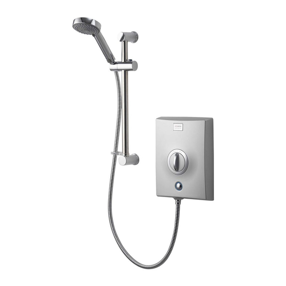
- Page 10 Quartz Electric shower with adjustable height head in Satin chrome Quartz Electric shower with adjustable height head in chrome Quartz Electric shower with adjustable height ure: head in White/chrome dure: Quartz Electric shower with adjustable Quartz Electric shower with adjustable...
- Page 11 Quartz Electric shower with adjustable Quartz Electric shower with adjustable height head in white/chrome height head in Graphite/chrome Components Components Literature not shown. Literature not shown. Quartz Electric Installation Guide 11...
- Page 12 Do not undertake any part of this IN THE INTERESTS OF ELECTRICAL SAFETY, A The Quartz Electric is supplied with universal fittings intended to secure the installation unless you are qualified to do so. Prior to starting, ensure that DEVICE (RCD) MUST BE INSTALLED IN ALL UK unit to a suitable wall.
- Page 13 Carefully detach the solenoid connector and pull the front casing clear. Carefully unscrew and remove the service tunnel and set aside. (This may be required if retrofitting this shower to an existing shower site). Tape the template provided onto the finished wall surface in the desired position and mark the 3 fixing points.
- Page 14 room for the nut on the compression elbow to be recessed into the wall. The pipe work must be connected to the elbow prior to fitting the shower unit to the wall. Turn on the water supply to the shower unit and check for leaks up stream of the shower unit.
- Page 15 Electrical installation BEFORE ANY ELECTRICAL CONNECTION IS ATTEMPTED, THE ELECTRICITY SUPPLY MUST BE TURNED OFF AT THE MAIN SWITCH. FAILURE TO DO SO COULD RESULT IN ELECTROCUTION. The electrical installation should be carried out by a qualified person in accordance with IEE (Institution of Electrical Engineers) wiring regulations (BS 7671).
- Page 16 socket outlet in the room must be situated at least 3 metres from the shower cubicle and protected by 30mA RCD. Switch must be outside Switch must Zone 2 Zone 2 be outside Zone 2 Zone 2 Zone 1 Zone 1 Zone 2 2.25m Zone 1...
- Page 17 unit or switch fuse (where fitted). otherwise the circuit will overheat.. The shower unit must be connected to its own independent electrical circuit. It MUST NOT be connected to a ring main, spur, socket outlet or lighting circuit, otherwise the circuit will overheat.. Check that the consumer unit (main fuse box): A has a main switch rating of 80A or above and B has a spare fuse way which will take the fuse/mcb (miniature circuit breaker) you need to fit.
- Page 18 Electrical rating Refer to the electrical rating diagram (shown overleaf) to determine the nominal current of the shower. The current rating of the supply cable must be at least that of the shower itself. Use the rating chart to choose a fuse or mcb with a rating of less than that of your chosen cable.
- Page 19 above, it may be necessary to utilise the service tunnel and alternative earth connection position. Replace the service tunnel and secure using the fixing screw provided. Unclip the earth terminal block and reposition it into the holder on the service tunnel. Any cable MUST NOT have the outer insulation stripped back beyond the bottom of back plate or service tunnel (if used) and must be protected from water as shown.
- Page 20 Earth bonding The installation must be earth bonded in accordance with current regulations Where earth bonding of the premises is not evident, it may be necessary to run bonding cable back to the earth terminal at the consumer unit. ! TH Shower head installation The shower head should be sited close to the shower unit, not necessarily on the same wall, but not so that the unit is subjected to continuous spray.
- Page 21 25mm above the spill over level of the bath or tray. If this is not achieved, then the hose restraint/gel hanger must be used Slide this onto the rail under the handset holder. To comply with current water supply regulations, the handset should not be able to pass a point 25mm above the spill over level of the bath or tray.
- Page 22 25mm above the spill over level of the bath or Please complete the commissioning procedure detailed below prior to connecting the tray. If this is not achieved, then the hose handset and hose. restraint/gel hanger must be used Slide this onto the rail under the handset holder.
- Page 23 section using a round file. Ensure the cover fits over cables and pipe correctly. Fix the self tapping screws a couple of turns into the fixing points at the top and bottom of the unit to aid locating the fixing points when securing the front casing to the back plate.
- Page 24 the piston. Attach the hose to the shower handset as detailed above after passing it through the hose restraint/gel hanger (if required) and place in the handset holder in a position where it can spray safely. Push the solenoid piston up until water sprays through the handset for a few seconds before releasing the piston.
- Page 25 Shower head installation position, may have to be slightly adjusted Pass the rail through the handset holder to enable the keyways to align. whilst keeping the slider button depressed. The shower head should be sited close to the shower unit, not necessarily on the same wall, but not so that the unit is subjected to continuous spray.
- Page 26 from the front of the shower casing. User Instructions To turn on and set the temperature 1 Turn on the isolating switch. 2 Press the start/stop button, the blue light ring should illuminate. 3 Rotate the control knob to give the desired temperature; clockwise for warmer and anticlockwise for cooler.
- Page 27 the handset holder button fully to enable the slider to be moved up or down the rail. 2 Angular adjustment is made by carefully but firmly pulling forwards or pushing back the shower head against the knuckle in the holder. 3 To select the desired spray pattern rotate the shower spray plate clockwise or anti-clockwise.
- Page 28 Please note that calls may be recorded for training and quality purposes. The company reserves the right to alter, change or modify the product specifications without prior warning. Trademark of Aqualisa Products Limited. Part No: 438301 Issue 05 Oct19 ™...
Need help?
Do you have a question about the QUARTZ Electric and is the answer not in the manual?
Questions and answers