Table of Contents
Advertisement
Quick Links
USER MANUAL AND SPECIFICATIONS
NI cRIO-FRC II
Reconfigurable Embedded Chassis with Integrated Intelligent
Real-Time Controller for FIRST Robotics Competition
5
4
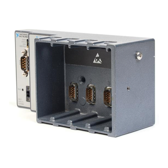
1. LEDs
2. RJ-45 Ethernet Port
3. Power Connector
This document describes how to connect the cRIO-FRC II to a network and how to use the
features of the cRIO-FRC II. This document also contains specifications for the cRIO-FRC II.
Figure 1. cRIO-FRC II Front Panel
1
3
2
4. Reset Button
5. RS-232 Serial Port
Advertisement
Table of Contents

Related Manuals for National Instruments cRIO-FRC II


Summary of Contents for National Instruments cRIO-FRC II
- Page 1 2. RJ-45 Ethernet Port 5. RS-232 Serial Port 3. Power Connector This document describes how to connect the cRIO-FRC II to a network and how to use the features of the cRIO-FRC II. This document also contains specifications for the cRIO-FRC II.
-
Page 2: Safety Guidelines For Hazardous Locations
Safety Guidelines for Hazardous Locations The cRIO-FRC II is suitable for use in Class I, Division 2, Groups A, B, C, D, T4 hazardous locations; Class I, Zone 2, AEx nA IIC T4 and Ex nA IIC T4 hazardous locations; and nonhazardous locations only. -
Page 3: Electromagnetic Compatibility Guidelines
Two M4 or number 8 flathead screws (for mounting the chassis without one of the listed mounting kits) • A number 2 Phillips screwdriver • Power supply • Ethernet cable NI cRIO-FRC II User Manual and Specifications | © National Instruments | 3... -
Page 4: Related Documentation
Mounting the CompactRIO Reconfigurable Embedded Chassis You can mount the chassis horizontally on a flat, vertical surface. The following figure shows the chassis mounted horizontally. Figure 2. cRIO-FRC II Mounted Horizontally 4 | ni.com | NI cRIO-FRC II User Manual and Specifications... - Page 5 25.4 mm (1 in.) 47.0 mm (1.85 in.) 87.3 mm (3.44 in.) 41.1 mm (1.62 in.) 4.0 mm 4.0 mm Cooling Outline (0.16 in.) (0.16 in.) 25.4 mm (1 in.) NI cRIO-FRC II User Manual and Specifications | © National Instruments | 5...
-
Page 6: Mounting The Chassis On A Panel
Panel or wall mounting is the best method for applications that are subject to high shock and vibration. You can use the NI 9904 panel mount kit to mount the cRIO-FRC II on a flat surface. Complete the following steps. - Page 7 If you do not have the NI 9904 panel mount kit and do not require the portability that the NI 9904 affords, you can mount the chassis directly on a flat surface using the mounting holes. Complete the following steps. NI cRIO-FRC II User Manual and Specifications | © National Instruments | 7...
-
Page 8: Mounting The Chassis On A Din Rail
M4 × 25 screws. NI provides these screws with the DIN rail mount kit. Tighten the screws to a maximum torque of 1.3 N · m (11.5 lb · in.). 8 | ni.com | NI cRIO-FRC II User Manual and Specifications... - Page 9 M3 × 20 screws. The adapter bracket and the screws are included in the kit. Refer to the NI 9901 documentation for information about mounting the chassis on a desktop. NI cRIO-FRC II User Manual and Specifications | © National Instruments | 9...
-
Page 10: Installing C Series I/O Modules In The Chassis
I/O modules. Align the I/O module with an I/O module slot in the chassis. The module slots are labeled 1 to 4, left to right. 10 | ni.com | NI cRIO-FRC II User Manual and Specifications... -
Page 11: Removing I/O Modules From The Chassis
Connect the chassis to an Ethernet network using the RJ-45 Ethernet port on the controller front panel. Use a standard Category 5 (CAT-5) or better shielded, twisted-pair Ethernet cable NI cRIO-FRC II User Manual and Specifications | © National Instruments | 11... -
Page 12: Wiring Power To The Chassis
The cRIO-FRC II filters and regulates the supplied power and provides power for all of the I/O modules. The cRIO-FRC II has one layer of reverse-voltage protection. Complete the following steps to connect a power supply to the chassis. -
Page 13: Controller Startup Options
Autoload VI on device reboot chassis reset option. To restart the cRIO-FRC II in safe mode, press and hold the Reset button for 5 s, then release it. The Status LED lights solid yellow, indicating that the cRIO-FRC II is in safe mode. Refer to the MAX help for information about safe mode. - Page 14 Connecting Serial Devices to the cRIO-FRC II The cRIO-FRC II has an RS-232 serial port to which you can connect devices such as displays or input devices. Use the Serial VIs to read from and write to the serial port from a LabVIEW RT application.
-
Page 15: Understanding Led Indications
USER1 USER FPGA1 POWER LED The POWER LED is lit while the cRIO-FRC II is powered on. This LED indicates that the power supply connected to the chassis is adequate. STATUS LED The STATUS LED is off during normal operation. The cRIO-FRC II indicates specific error... -
Page 16: Troubleshooting Network Communication
If you want the controller to attempt a new DHCP connection, proceed to step 2. Press and hold the Reset button for 5 s, then release it. The cRIO-FRC II attempts to establish a new DHCP connection. If it fails, it assigns itself a link-local IP address. If the DHCP connection is successful and appropriate for your application, skip to step 4. -
Page 17: Rs-232 Serial Port
You must use a UL Listed ITE power supply marked LPS with the cRIO-FRC II. Recommended power supply 24 W, 24 VDC Power consumption 15 W maximum Power supply input range 9 V to 30 V NI cRIO-FRC II User Manual and Specifications | © National Instruments | 17... -
Page 18: Physical Characteristics
Caution Do not connect the cRIO-FRCII to signals or use for measurements within Measurement Categories II, III, or IV. 18 | ni.com | NI cRIO-FRC II User Manual and Specifications... -
Page 19: Hazardous Locations
ICES-001: Class A emissions Note For EMC declarations and certifications, and additional information, refer to Online Product Certification section. Note For EMC compliance, operate this product according to the documentation. NI cRIO-FRC II User Manual and Specifications | © National Instruments | 19... -
Page 20: Online Product Certification
Operating humidity (IEC 60068-2-78) 10% RH to 90% RH, noncondensing Storage humidity (IEC 60068-2-78) 5% RH to 95% RH, noncondensing Pollution Degree Maximum altitude 2,000 m Indoor use only. 20 | ni.com | NI cRIO-FRC II User Manual and Specifications... -
Page 21: Worldwide Support And Services
NI Factory Installation Services, repairs, extended warranty, and other services. Visit ni.com/register to register your NI product. Product registration facilitates technical support and ensures that you receive important information updates from NI. NI cRIO-FRC II User Manual and Specifications | © National Instruments | 21... - Page 22 CONTAINED HEREIN AND SHALL NOT BE LIABLE FOR ANY ERRORS. U.S. Government Customers: The data contained in this manual was developed at private expense and is subject to the applicable limited rights and restricted data rights as set forth in FAR 52.227-14, DFAR 252.227-7014, and DFAR 252.227-7015. © 2011—2016 National Instruments. All rights reserved. 375770B-01 Mar16...
Need help?
Do you have a question about the cRIO-FRC II and is the answer not in the manual?
Questions and answers