Toro Greensmaster 1000 Operator's Manual
Hide thumbs
Also See for Greensmaster 1000:
- Operator's manual (44 pages) ,
- Operator's manual (32 pages) ,
- Operator's manual (24 pages)

Related Manuals for Toro Greensmaster 1000


Summary of Contents for Toro Greensmaster 1000
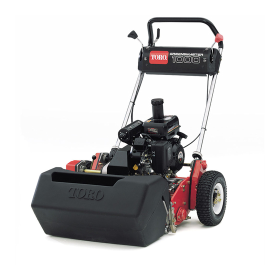
- Page 1 Form No. 3430-991 Rev A Greensmaster ® 1000 Mower Model No. 04810—Serial No. 400000000 and Up *3430-991* A Register at www.Toro.com. Original Instructions (EN)
- Page 2 This product complies with all relevant European Whenever you need service, genuine Toro parts, or directives; for details, please see the separate product additional information, contact an authorized Toro specific Declaration of Conformity (DOC) sheet. distributor and have the model and serial numbers of your product ready.
-
Page 3: Table Of Contents
Contents Servicing the Traction-Interlock Switch ..............29 Brake Maintenance ..........30 Safety ............... 4 Adjusting the Service/Parking Brake....30 General Safety........... 4 Belt Maintenance ..........31 Safety and Instructional Decals ......4 Adjusting the Belts ..........31 Setup ................ 7 Replacing the Differential Belt...... -
Page 4: Safety
Safety • Do not put your hands or feet near moving components of the machine. • Do not operate the machine without all guards This machine has been designed in accordance and other safety protective devices in place and with EN ISO 5395 and ANSI B71.4-2017 and meets functioning properly on the machine. - Page 5 decal115-1720 115-1720 1. Forward 3. Neutral 2. Drive wheel decal120-2727 120-2727 1. Brake—to engage, pull the 2. Parking brake—to lock, lever toward the handle; pull the lever toward the decal133-8062 to disengage, release the handle, press the button 133-8062 lever. in and release the lever against the locking button;...
- Page 6 decal138-2138 138-2138 1. Poisonous fumes or 4. Warning— disconnect the decal130-8322 toxic gases, asphyxiation spark plug wire before 130-8322 performing maintenance. hazard—do not run the 1. Use only gasoline that 3. Do not use gasoline that engine in an enclosed contains 10% ethanol by contains more than 10% space.
-
Page 7: Setup
Install the transport wheels (optional). – No parts required Adjust the cutting unit. Operator Presence Kit (order separately; Install the operator presence kit. contact your authorized Toro distributor) Production-year decal Install the CE decals (if required). CE-mark decal Grass basket Install the grass basket. -
Page 8: Installing And Adjusting The Handle
Installing and Adjusting the Handle Parts needed for this procedure: Handle Cable tie Installing the Handle Remove the bolts (5/16 inch), locknuts, ring pins, and hairpin cotters that secure the bottom of the handle arms to each side of the machine (Figure g240404 Figure 4... -
Page 9: Installing The Transport-Wheel Shafts
Adjusting the Handle Refer to Figure 6 for this procedure. g017590 Figure 5 g240512 1. Cable ties Figure 6 1. Handle 3. Ring pin 2. Hairpin cotter Remove the hairpin cotters from the ring pins on each side of the machine. While supporting the handle, remove the ring pins from each side and raise or lower the handle to the desired operating position. -
Page 10: Installing The Transport Wheels
Thread the right wheel shaft into the drive pulley on the right side of the machine (Figure Note: The right wheel shaft has left-hand threads. g007595 Figure 7 g017591 Figure 8 1. Right wheel shaft 1. Locking clip Torque the shaft to 88 to 101 N∙m (65 to 75 ft-lb). Rotate the wheel back and forth until it slides Repeat steps through... -
Page 11: Installing The Operator Presence Kit
To comply with EN ISO 5395 and ANSI B71.4-2017, install the Operator Presence Kit (Model No. 112-9282); refer to the kit Installation Instructions. Contact your authorized Toro distributor to acquire this kit. Installing the Grass Basket Parts needed for this procedure:... -
Page 12: Breaking In The Machine
Product Overview Breaking in the Machine No Parts Required Procedure Only 8 hours of mowing operation is required for the break-in period. The first several hours of operation are critical to future dependability of the machine. You must monitor the machine performance closely so that minor difficulties, which could lead to major problems, are noted and can be corrected. -
Page 13: Controls
Controls g016976 Figure 13 g017592 Figure 12 Parking Brake 1. Traction-drive lever 5. Service brake The parking brake (Figure 14) is located at the base of 2. Throttle control 6. Parking brake the service brake. Fully engage the service brake and 3. -
Page 14: Specifications
Contact your Authorized Service Dealer or authorized Toro distributor or go to www.Toro.com for a list of all approved attachments and accessories. To ensure optimum performance and continued safety certification of the machine, use only genuine Toro replacement parts and accessories. -
Page 15: Before Operation
Operation containers on the ground, away from the vehicle before filling. • Remove equipment from the truck or trailer and Note: Determine the left and right sides of the refuel it on the ground. If this is not possible, refuel machine from the normal operating position. -
Page 16: Filling The Fuel Tank
Filling the Fuel Tank WARNING Fuel is harmful or fatal if swallowed. DANGER Long-term exposure to vapors can cause serious injury and illness. In certain conditions, fuel is extremely flammable and highly explosive. A fire or • Avoid prolonged breathing of vapors. explosion from fuel can burn you and others •... -
Page 17: Setting The Machine To Match Turf Conditions
Use the following tables to set the machine to match turf conditions. Bedbars: Standard and Optional Part Number Description Aggressiveness Comments 112-9281-01 Standard Less Standard Greensmaster 1000 112-9279-03 Aggressive More Bedknives: Standard and Optional Part Number Description Height of Cut Range Comments... -
Page 18: Checking The Interlock-Switch Operation
Securely fasten the machine to the trailer. switches before operating the machine. Note: You can use the Toro Trans Pro trailer to Push the kickstand down with your foot and pull transport the machine. For instructions on loading the up and back on the handle to raise the wheels trailer, refer to your trailer Operator’s Manual. -
Page 19: Opening And Closing The Fuel-Shutoff Valve
During Operation During Operation Safety General Safety • The owner/operator can prevent and is responsible for accidents that may cause personal injury or property damage. • Wear appropriate clothing, including eye protection; long pants; substantial, slip-resistant footwear; and hearing protection. Tie back long hair and do not wear loose clothing or loose jewelry. -
Page 20: Starting The Engine
– Before leaving the operating position Note: Ensure that the spark-plug wire is installed on • Use only accessories and attachments approved the spark plug. by The Toro® Company. Ensure that the traction and reel drive levers are in the D position. ISENGAGED Slope Safety... -
Page 21: Operating Tips
1. Alignment stripes Operating the Machine in Low Light Conditions Use the LED Light Kit when you operate the machine in low light conditions; contact your authorized Toro distributor. Important: Do not use other light systems with this machine, as they will not operate properly... -
Page 22: After Operation
After Operation After Operation Safety General Safety • Shut off the engine, remove the key (if equipped), and wait for all movement to stop before you leave the operator’s position. Allow the machine to cool before adjusting, servicing, cleaning, or storing it. •... -
Page 23: Maintenance
– Wait for all movement to stop. • To ensure safe, optimal performance of the • Allow machine components to cool before machine, use only genuine Toro replacement performing maintenance. parts. Replacement parts made by other • If possible, do not perform maintenance while the manufacturers could be dangerous, and such use machine is running. -
Page 24: Daily Maintenance Checklist
Daily Maintenance Checklist Important: Duplicate this page for routine use. Maintenance For the week of: Check Item Mon. Tues. Wed. Thurs. Fri. Sat. Sun. Check the safety interlock operation. Check the parking brake operation. Check the fuel level. Check the engine oil level. -
Page 25: Pre-Maintenance Procedures
Pre-Maintenance Lubrication Procedures Greasing the Machine Preparing the Machine for Service Interval: Every 25 hours Maintenance Lubricate the 12 grease fittings on the mower using No. 2 lithium grease. For best results, use a hand-operated grease gun. WARNING The grease fitting locations are as follows: While you are maintaining or adjusting the •... -
Page 26: Engine Maintenance
Engine Maintenance Engine Safety • Do not change the governor speed or overspeed the engine. • Run the engine dry or remove the fuel with a hand pump; never siphon the fuel. If you must drain the fuel tank, do it outdoors. g016981 Figure 24 Servicing the Engine Oil... -
Page 27: Changing The Engine Oil
Position the machine so that the engine is level, If the engine-oil level is incorrect, add or drain oil and clean the area around the oil-fill tube (Figure to correct the level; refer to Changing the Engine 27). Oil (page 27). -
Page 28: Servicing The Air Cleaner
Servicing the Air Cleaner Service Interval: Before each use or daily Every 50 hours/Every 3 months (whichever comes first) Every 300 hours/Yearly (whichever comes first) Important: Do not operate the engine without the air filter assembly; extreme engine damage will occur. Shut off the engine and wait for all moving parts to stop;... -
Page 29: Servicing The Spark Plug
Servicing the Spark Plug Electrical System Maintenance Service Interval: Every 100 hours/Every 6 months (whichever comes first) Every 300 hours/Yearly (whichever comes first) Servicing the Use an NGK BPR6ES spark plug or equivalent. Traction-Interlock Switch Shut off the engine and wait for all moving parts to stop;... -
Page 30: Brake Maintenance
Brake Maintenance Adjusting the Service/Parking Brake If the service/parking brake slips during operation, adjust it. Engage the service brake, push in the parking brake knob, and allow the service brake to rest on the parking-brake pin (Figure 32). g008215 Figure 33 1. -
Page 31: Belt Maintenance
Belt Maintenance Adjusting the Belts Ensure that the belts are properly tensioned to ensure proper operation of the machine and prevent unnecessary wear. Check the belts frequently. Adjusting the Reel-Drive Belt Remove the belt-cover mounting fasteners and g007627 the belt cover to expose the belt (Figure 36). - Page 32 Important: Do not over-tension the belt. Loosen the idler-pulley mounting nut and pivot the idler pulley clockwise against the Tighten the nut to lock the adjustment. backside of the belt until the desired belt Install the belt cover by placing it in position. tension is attained (Figure 39).
- Page 33 While maintaining a slight gap between the To push or pull the machine easier without cover seal and the side plate, install each starting the engine, adjust the belt guide (Figure mounting bolt until the threads engage in the 42, inset) as follows: insert.
-
Page 34: Replacing The Differential Belt
Replacing the Differential Rotate both housings back into the upright position and secure them to the side plate with Belt the bolts and nuts that you previously removed. Adjust the differential belt tension; refer to Remove the bolts that secure the traction drive Adjusting the Differential Belt (page 32). -
Page 35: Controls System Maintenance
Controls System Cutting Unit Maintenance Maintenance Blade Safety Adjusting the Traction Use care when checking the cutting-unit reel. Wear gloves and use caution when servicing the reel. Control A worn or damaged blade or bedknife can break, and a piece could be thrown toward you or bystanders, Follow these steps to remove slack from the traction resulting in serious personal injury or death. -
Page 36: Adjusting The Bedknife To The Reel
Important: Do not tip the machine at an angle greater than 25°. Tipping the machine beyond 25° leads to oil leaking into the combustion chamber and/or fuel leaking out of the fuel-tank cap. Rotate the reel so that a blade crosses the bedknife edge between the first and second bedknife screw heads on the right side of the cutting unit... -
Page 37: Adjusting The Height-Of-Cut
reel and bedknife, perpendicular to the bedknife height-of-cut. The distance between the bottom (Figure 48). Slowly rotate the reel forward; it of the screw head and the face of the bar is the should cut the paper. height of cut. g000489 Figure 50 1. -
Page 38: Adjusting The Grass Shield Height
Adjusting the Cut-Off Bar • Use the middle position without a groomer. • Use the third position in extremely undulating Adjust the cut-off bar to ensure that the clippings are turf conditions. cleanly discharged from the reel area. Loosen the screws that secure the top bar (Figure 54) to the cutting unit. -
Page 39: Servicing The Bedbar
Insert a 1/2 inch-drive extension bar, connected to the backlapping machine, into the square hole in the center of the reel pulley. Backlap according to the procedure in the Toro Sharpening Reel and Rotary Mowers Manual, Form 80-300 PT. g014780... -
Page 40: Storage
Repair or replace any part that is worn or damaged. Paint all scratched or bare metal surfaces. Paint is available from your authorized Toro distributor. Store the machine in a clean, dry garage or storage area. Cover the machine to protect it... - Page 41 Notes:...
- Page 42 The Toro Company (“Toro”) respects your privacy. When you purchase our products, we may collect certain personal information about you, either directly from you or through your local Toro company or dealer. Toro uses this information to fulfil contractual obligations - such as to register your warranty, process your warranty claim or to contact you in the event of a product recall - and for legitimate business purposes - such as to gauge customer satisfaction, improve our products or provide you with product information which may be of interest.
- Page 43 Countries Other than the United States or Canada Customers who have purchased Toro products exported from the United States or Canada should contact their Toro Distributor (Dealer) to obtain guarantee policies for your country, province, or state. If for any reason you are dissatisfied with your Distributor's service or have difficulty obtaining guarantee information, contact your Authorized Toro Service Center.
- Page 44 While the exposure from Toro products may be negligible or well within the “no significant risk” range, out of an abundance of caution, Toro has elected to provide the Prop 65 warnings. Moreover, if Toro does not provide these warnings, it could be sued by the State of California or by private parties seeking to enforce Prop 65 and subject to substantial penalties.