Toro Greensmaster 04052 Operator's Manual
Walk-behind mower
Hide thumbs
Also See for Greensmaster 04052:
- Operator's manual (32 pages) ,
- Operator's manual (24 pages) ,
- Operator's manual (32 pages)

Related Manuals for Toro Greensmaster 04052


Summary of Contents for Toro Greensmaster 04052
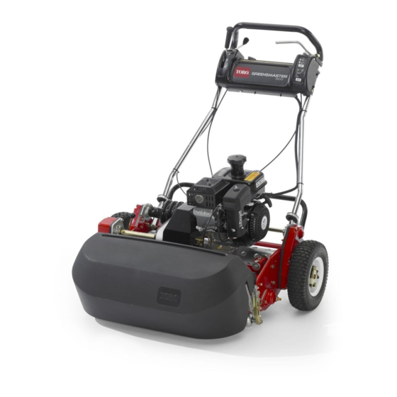
- Page 1 Form No. 3359-317 Rev D Greensmaster ® 1000 and 1600 Walk-Behind Mower Model No. 04052—Serial No. 280000001 and Up Model No. 04060—Serial No. 280000001 and Up Register at www.Toro.com. Original Instructions (EN)
-
Page 2: Introduction
Whenever you need service, genuine Toro parts, or additional information, contact an Authorized Service Dealer or Toro Customer Service and have the model and serial numbers of your product ready. The model and serial numbers are located on a plate on the rear frame. -
Page 3: Table Of Contents
Setting the Machine to Match Turf Sound Pressure............. 6 Conditions ............. 33 Sound Power ............6 Servicing the Bedbar........... 34 Vibration (Model 04052) ........6 Backlapping the Reel .......... 34 Vibration (Model 04060) ........6 Storage............... 35 Safety and Instructional Decals ......7 Setup................ -
Page 4: Safety
Safety • Warning—Fuel is highly flammable. Take the following precautions: This machine meets or exceeds CEN standard – Store fuel in containers specifically designed for EN 836:1997, ISO standard 5395:1990, and ANSI this purpose. B71.4-2004 specifications in effect at the time of –... -
Page 5: Toro Mower Safety
The following list contains safety information specific • Slow down and use caution when making turns to Toro products or other safety information that you and crossing roads and sidewalks. Stop reels if not must know that is not included in the CEN, ISO, or mowing. -
Page 6: Sound Pressure
Keep everyone away. • To ensure safety and accuracy, have an Authorized Toro Distributor check the maximum engine speed with a tachometer. Maximum governed engine speed should be 3600 ± 100 RPM. • If major repairs are ever needed or if assistance is desired, contact an Authorized Toro Distributor. -
Page 7: Safety And Instructional Decals
Safety and Instructional Decals Safety decals and instructions are easily visible to the operator and are located near any area of potential danger. Replace any decal that is damaged or lost. 93-9356 1. Entanglement hazard—stay away from moving parts. 93-7348 1. - Page 8 93-9886 1. Use unleaded gasoline. 93-6085 1. Fast 3. Slow 2. Continuous variable setting 93-8064 1. Warning—read the instructions before servicing or performing maintenance. 2. Cutting hazard of hand or foot—stop the engine and wait for moving parts to stop. 112-9408 1.
- Page 9 115-1720 1. Forward 3. Neutral 2. Drive wheel 104-2618 1. Disengage-lever position 3. Engage-lever position 2. Parking brake...
-
Page 10: Setup
Setup Loose Parts Use the chart below to verify that all parts have been shipped. Procedure Description Qty. Handle Install the handle. Cable tie Kickstand assembly Install the kickstand (model 04035 only). Spring Wheel shaft, right Wheel shaft, left Install the transport wheels. Transport wheels (obtain separately) –... -
Page 11: Installing The Kickstand (Model 04060 Only)
5. Squeeze the handle ends inward and install them on 2. While supporting the handle, remove the ring pins the mounting pins (Figure 3). from each side and raise or lower the handle to the desired operating position (Figure 2). 3. -
Page 12: Installing The Transport Wheels
Installing the Transport Wheels Parts needed for this procedure: Wheel shaft, right Wheel shaft, left Transport wheels (obtain separately) Procedure 1. Push the kick stand down with your foot and pull Figure 7 up on the handle to support the mower on the kick 1. -
Page 13: Product Overview
Product Overview Controls Installing the Grass Basket Parts needed for this procedure: Grass basket Procedure Grasp basket by top lip and slide it onto the basket mounting rods (Figure 8). Figure 9 1. Traction drive lever 3. On/off switch 2. Throttle control 4. -
Page 14: Specifications
Open. Move the lever to the closed position when Authorized Service Dealer or Distributor or go to storing or transporting machine. Open the valve before www.Toro.com for a list of all approved attachments starting the engine. and accessories. Recoil Starter... -
Page 15: Operation
Operation Note: Determine the left and right sides of the In certain conditions, gasoline is extremely machine from the normal operating position. flammable and highly explosive. A fire or explosion from gasoline can burn you and others and can damage property. Think Safety First •... - Page 16 In certain conditions during fueling, static electricity can be released causing a spark which can ignite the gasoline vapors. A fire or explosion from gasoline can burn you and others and can damage property. • Always place gasoline containers on the ground away from your vehicle before filling.
-
Page 17: Checking The Interlock Switch Operation
Checking the Interlock Switch out because rope may break or recoil assembly may be damaged. Operation 7. Move the choke to the Off position as the engine Service Interval: Before each use or daily warms up. Stopping the Engine 1. Move the traction and reel drive controls to the If safety interlock switches are disconnected Disengaged position, the throttle control to the or damaged the machine could operate... -
Page 18: Operating Tips
for fundamental suggestions to obtain the utmost performance from your mower. Important: Excessive operation of the cutting unit with the absence of grass clippings (lubricant) can damage the cutting unit. 1. Start the engine, set the throttle at reduced speed, push down on the handle to raise the cutting unit, move the traction lever to the Engaged position, and transport the mower onto collar of the green. -
Page 19: Maintenance
Maintenance Note: Determine the left and right sides of the machine from the normal operating position. Recommended Maintenance Schedule(s) Maintenance Service Maintenance Procedure Interval • Change the engine oil. After the first 8 hours • Clean the fuel filter. After the first 25 hours •... -
Page 20: Daily Maintenance Checklist
Daily Maintenance Checklist Important: Duplicate this page for routine use. Maintenance For the week of: Check Item Mon. Tues. Wed. Thurs. Fri. Sat. Sun. Check the safety interlock operation. Check the parking brake operation. Check the fuel level. Check the engine oil level. -
Page 21: Lubrication
Lubrication Greasing the Machine Service Interval: Every 25 hours Lubricate the 13 grease fittings on the mower using a No. 2 multipurpose lithium base grease. A hand operated grease gun is recommended for best results. The grease fitting locations are as follows: Figure 16 •... -
Page 22: Engine Maintenance
Engine Maintenance Servicing the Engine Oil Service Interval: After the first 8 hours—Change the engine oil. Before each use or daily—Check the engine oil level. Every 50 hours—Change the engine oil. (More frequently in dusty or dirty conditions) The crankcase must be filled with approximately 20 fluid ounces of proper viscosity oil before staring. -
Page 23: Servicing The Air Cleaner
4. Push down on the handle to tip the mower and the engine backward, allowing more oil to run into the drain pan. 5. Install the drain plug and refill the crankcase with the proper oil; refer to Checking the Engine Oil Level. Servicing the Air Cleaner Service Interval: Every 25 hours—Clean and oil the air cleaner foam element. -
Page 24: Fuel System Maintenance
Fuel System 3. Set the air gap at 0.028 to 0.032 inch (0.05 to 0.07 cm) (Figure 24). Maintenance Cleaning the Fuel Filter Service Interval: After the first 25 hours Every 50 hours 1. Close the fuel shut off valve and unscrew the bowl Figure 24 from the filter body (Figure 25). -
Page 25: Electrical System Maintenance
Brake Maintenance Electrical System Maintenance Adjusting the Service/Parking Brake Servicing the Interlock Switch If service/parking brake slips when operated, an Use the following procedure if the switch needs adjustment is required. adjustment or replacement. 1. Move service/parking brake lever to the Off 1. -
Page 26: Belt Maintenance
Belt Maintenance Important: Do not over tension the belt. B. Tighten the nut to lock the adjustment. Adjusting the Belts 4. Install the belt cover by placing it in position. 5. While maintaining a slight gap between the cover Service Interval: Every 300 hours—Check the seal and the side plate, install each mounting bolt condition and tension of belts. - Page 27 Adjusting the Primary V-Belts the belt until the desired belt tension is attained (Figure 31). 1. To adjust the belt tension on primary V-belts, first Important: Do not over tension the belt. check the adjustment of the traction control. Refer to Adjusting the Traction Control.
-
Page 28: Replacing The Differential Belt
Figure 34 Figure 35 1. Primary V-belts 3. Idler pulley 3. Right rear bearing housing 1. Differential cover sections 2. Belt guide 2. Front clutch housing 7. Tighten the mounting screws and check the 5. Loosen the idler pulley mounting nut on the alignment. -
Page 29: Controls System Maintenance
Controls System Cutting Unit Maintenance Maintenance Leveling the Rear Drum to the Reel Adjusting the Traction Control 1. Position the machine on a flat, level surface, If traction control does not engage or it slips during preferably a precision steel work plate. operation, an adjustment is required. -
Page 30: Adjusting The Bedknife To The Reel
1. Position the machine on a flat, level work surface. backlap or grind the cutting unit to achieve the sharp 2. Ensure that the reel contact is removed by turning edges needed for precision cutting; refer to the Toro the bedbar adjusting screws counterclockwise reel sharpening manual. -
Page 31: Adjusting The Grass Shield Height
Important: When set properly, the rear and front rollers will contact the gauge bar and the screw will be snug against the bedknife. This ensures the height-of-cut is identical at both ends of the bedknife. 7. Tighten nuts to lock the adjustment. Important: To avoid scalping on undulating turf, ensure that the roller supports are positioned rearward (the roller closer to the reel). -
Page 32: Adjusting The Cut-Off Bar
Bedbar Identification cm). Loosen the bolts and nuts securing each end of the shield to the sideplate and adjust the shield to To determine if the bedbar is standard or aggressive, the correct height. check the left bedbar mounting ears. If the mounting 3. -
Page 33: Setting The Machine To Match Turf Conditions
Setting the Machine to Match Turf Conditions Use the following table to set the machine to match turf conditions. Greensmower Cutting Unit Set-up Matrix Bedbars: Standard and Optional Part Number Description Mower Aggressiveness Comments 112-9281-01 Standard Greensmaster 1000 Less Standard Greensmaster 1000 112-9279-03 Aggressive Greensmaster 1000... -
Page 34: Servicing The Bedbar
2. Insert a 1/2 inch socket extension, connected to the backlapping machine, into the square hole in the center of the reel pulley. 3. Backlap according to the procedure in the Toro Sharpening Reel and Rotary Mowers Manual, Form No. 80-300 PT. -
Page 35: Storage
Storage 1. Remove grass clippings, dirt, and grime from the external parts of the entire machine, especially the engine. Clean dirt and chaff from the outside of the engine’s cylinder head fins and blower housing. Important: You can wash the machine with mild detergent and water. - Page 36 Countries Other than the United States or Canada Customers who have purchased Toro products exported from the United States or Canada should contact their Toro Distributor (Dealer) to obtain guarantee policies for your country, province, or state. If for any reason you are dissatisfi ed with your Distributor’s service or have diffi...