Table of Contents
Advertisement
Advertisement
Table of Contents

Related Manuals for Toro TX 427 Series


Summary of Contents for Toro TX 427 Series
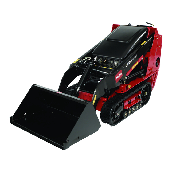
- Page 1 Form No. 3405-118 Rev B TX 427 Narrow Track Compact Tool Carrier Model No. 22342HD—Serial No. 314000001 and Up Model No. 22342HD—Serial No. 315000001 and Up Model No. 22342HD—Serial No. 316000001 and Up *3405-118* B Register at www.Toro.com. Original Instructions (EN)
- Page 2 You are responsible for operating the product properly and safely. You may contact Toro directly at www.Toro.com for product DANGER safety and operation training materials, accessory information, help finding a dealer, or to register your product.
-
Page 3: Table Of Contents
and Note emphasizes general information worthy of special Adjusting the Tracking of the Traction Control, attention. Full Forward Position ..........40 Hydraulic System Maintenance ........41 Replacing the Hydraulic Filter ........41 Contents Changing the Hydraulic Fluid........42 Checking the Hydraulic Lines........43 ................44 Safety ................4 Checking the Shear Bolt on the Platform....44 Safe Operating Practices........... -
Page 4: Safety
Safety • Wear appropriate clothing including safety glasses, long pants, safety shoes, and hearing protection. Tie back long hair. Do not wear jewelry. Improper use or maintenance by the operator or owner • can result in injury. To reduce the potential for injury, Inspect the area where the equipment is to be used and comply with these safety instructions and always remove all objects such as rocks, toys, and wire which can... - Page 5 Do not carry a load with the arms raised. Always carry hide obstacles. loads close to the ground. • Use only Toro-approved attachments. Attachments can • Do not over-load the attachment and always keep the change the stability and the operating characteristics of load level when raising the loader arms.
- Page 6 Stop and inspect the equipment if you strike an object. Make any necessary repairs before starting. • Use only genuine Toro replacement parts to ensure that original standards are maintained. • Battery acid is poisonous and can cause burns. Avoid contact with skin, eyes, and clothing.
-
Page 7: Stability Data
Stability Data The following tables list the maximum slope recommended for the traction unit in the positions listed in the tables. Slopes over the listed degree may cause the traction unit to become unstable. The data in the tables assume that the loader arms are fully lowered;... -
Page 8: Slope Indicator
Slope Indicator G011841 Figure 3 This page may be copied for personal use. 1. To determine the maximum slope you can safely operate the machine on, refer to the Stability Data section. Use the slope indicator to determine the degree of slope of hills before operating. Do not operate this machine on a slope greater than that specified in the Stability Data section. -
Page 9: Safety And Instructional Decals
Safety and Instructional Decals Safety decals and instructions are easily visible to the operator and are located near any area of potential danger. Replace any decal that is damaged or lost. 58-6520 99-9935 1. Grease 1. Tipping hazard—read the Operator’s Manual; the maximum load rating is 234 kg (515 lbs). - Page 10 112-2744 1. Read the Operator’s Manual. 4. Lower the platform from the unlocked position to use. 2. Platform locked in the storage position. 5. Warning—read the Operator’s Manual. 3. Lift the platform up to unlock. 6. Tipping hazard—do not step off the platform with a raised load.
- Page 11 115-4862 1. Loader-valve 2. Loader-valve lock—locked lock—unlocked 115-4860 1. Warning—read the Operator's Manual. 2. Warning—set the parking brake, shut off the engine, remove the ignition key and lower the loader arms before leaving the machine. 3. Crushing hazard—install the cylinder lock and read the instructions before servicing or performing maintenance. 4.
-
Page 12: Product Overview
Product Overview Figure 4 1. Track 5. Loader arms 9. Mount plate 13. Fuel tank 2. Track-adjustment chamber 6. Hood 10. Tie-down/lift loop 14. Reverse-safety plate 3. Lift cylinder 7. Auxiliary-hydraulic couplers 11. Control panel 4. Cylinder lock 8. Tilt cylinder 12. - Page 13 Traction Control • To turn right, rotate the traction control clockwise (Figure G008131 Figure 6 Figure 9 1. Reference bar (does not move to give you a reference point and a fixed handle to hold while operating the traction unit) •...
- Page 14 Auxiliary-Hydraulics Lever To operate a hydraulic attachment in the forward direction, rotate the auxiliary-hydraulics lever rearward and pull it down to the reference bar (Figure 13, number 1). To operate a hydraulic attachment in reverse direction, rotate the hydraulics lever rearward, then move it left into the upper slot (Figure 13, number 2).
-
Page 15: Specifications
(3.5 ft Attachments/Accessories A selection of Toro approved attachments and accessories is available for use with the machine to enhance and expand its capabilities. Contact your Authorized Service Dealer or Distributor or go to www.Toro.com for a list of all approved attachments and accessories. -
Page 16: Operation
Operation DANGER In certain conditions, fuel is extremely flammable Note: Determine the left and right sides of the machine and highly explosive. A fire or explosion from fuel from the normal operating position. can burn you and others and can damage property. Important: Before operating, check the fuel and oil •... -
Page 17: Checking The Engine-Oil Level
Note: The cap is tethered to the fuel tank. 8. If the oil level is low, clean around the oil-filler cap and remove the cap (Figure 16). 4. Add unleaded fuel to the fuel tank, until the level is just below the bottom of the filler neck. -
Page 18: Starting And Stopping The Engine
Note: If outdoor temperature is below freezing, store the traction unit in a garage to keep it warmer and aid in starting. Stopping the Engine 1. Move the throttle lever 3/4 of the way to the F position. 2. Lower the loader arms to the ground. 3. -
Page 19: Moving A Non-Functioning Traction Unit
Moving a Non-Functioning Using the Cylinder Lock Traction Unit WARNING Important: Do not tow or pull the traction unit without The loader arms may lower when in the raised first opening the tow valves, or the hydraulic system will position crushing anyone under them. be damaged. -
Page 20: Using Attachments
These systems are built into the TX, and you should ignore any references to them. Installing an Attachment Important: Use only Toro-approved attachments. Attachments can change the stability and the operating characteristics of the traction unit. The warranty of the traction unit may be voided if used with unapproved attachments. - Page 21 Connecting the Hydraulic Hoses Maximum Material Density at Capacity The density of materials being moved by the bucket varies WARNING and therefore so will the amount of a given material that can be carried by the bucket before the maximum load rating is Hydraulic fluid escaping under pressure can reached.
- Page 22 the mounting plate, the platform slides down into the tube Maximum Density for Capacity Chart and locks in place. Bucket Capacity 1937 kg/m (121 lb/ft Heaped Bucket 2369 kg/m (147 lb/ft Struck (leveled) Bucket Material Density Chart Material Density (approximate) Caliche 1250 kg/m (78 lb/ft...
-
Page 23: Securing The Traction Unit For Transport
Removing an Attachment Loading the Machine 1. Lower the attachment to the ground. Use extreme caution when loading or the unloading machine onto a trailer or a truck. Use a full-width ramp that is wider 2. Shut off the engine. than the machine for this procedure. - Page 24 WARNING Loading a machine onto a trailer or truck increases the possibility of tip-over and could cause serious injury or death. • Use extreme caution when operating a machine on a ramp. • Use only a full-width ramp; do not use individual ramps for each side of the machine.
-
Page 25: Maintenance
Maintenance Note: Determine the left and right sides of the machine from the normal operating position. Recommended Maintenance Schedule(s) Maintenance Service Maintenance Procedure Interval • Replace the hydraulic filter. After the first 8 hours • Change the engine oil and filter. After the first 50 hours •... -
Page 26: Premaintenance Procedures
CAUTION If you leave the key in the ignition switch, someone could accidently start the engine and seriously injure you or other bystanders. Remove the key from the ignition and disconnect the wire from the spark plug before you do any maintenance. -
Page 27: Closing The Rear-Access Cover
Closing the Rear-Access Cover 1. Move the rear-access cover in place over the back of the traction unit making sure that the tabs line up in the slots. 2. Push the access cover forward, lining up the hand-knob screws with the threaded holes in the machine. 3. -
Page 28: Lubrication
Lubrication Greasing the Traction Unit Service Interval: Before each use or daily (Grease immediately after every washing.) Grease Type: General-purpose grease. 1. Lower the loader arms and shut off the engine. Remove the key. 2. Clean the grease fittings with a rag. 3. -
Page 29: Engine Maintenance
Engine Maintenance Ensure that the cover is seated correctly and seals with the air-cleaner body. • If the service indicator is red, replace the air filter Servicing the Air Cleaner as described in Replacing the Filters (page 29). Service Interval: Before each use or daily—Check the Replacing the Filters air-filter-service indicator. -
Page 30: Servicing The Engine Oil
Servicing the Engine Oil Service Interval: After the first 50 hours Every 100 hours—Change the engine oil. Every 200 hours—Change the oil filter. Note: Change the oil and filter more frequently when operating conditions are extremely dusty or sandy. Oil Type: Detergent oil (API service SG, SH, SJ, or higher) Crankcase Capacity: with filter, 2.0 L (2.1 US qt) Viscosity: See table below G018430... -
Page 31: Servicing The Spark Plugs
7. Install the replacement oil filter to the filter adapter. Turn the oil filter clockwise until the rubber gasket contacts the filter adapter, then tighten the filter an additional 1/2 turn. 8. Fill the crankcase with the proper type of new oil; refer Changing the Oil (page 30). -
Page 32: Fuel System Maintenance
Checking the Spark Plugs Fuel System 1. Look at the center of both spark plugs (Figure 41). If Maintenance you see light brown or gray on the insulator, the engine is operating properly. A black coating on the insulator usually means that the air cleaner is dirty. Changing the Fuel Filter Important: Never clean the spark plugs. -
Page 33: Draining The Fuel Tank
Draining the Fuel Tank Electrical System Maintenance DANGER In certain conditions, fuel is extremely flammable Servicing the Battery and highly explosive. A fire or explosion from fuel can burn you and others and can damage property. Service Interval: Every 100 hours—Check the •... - Page 34 3. Remove the battery from the traction unit. Important: Never fill the battery with distilled water while the battery is installed in the traction unit. Electrolyte could be spilled on other parts and cause corrosion. 4. Clean the top of the battery with a paper towel. 5.
-
Page 35: Drive System Maintenance
Drive System Maintenance Servicing the Tracks Service Interval: After the first 50 hours—Check and adjust the track tension. Before each use or daily—Clean the tracks. Before each use or daily—Check the tracks for G003792 excessive wear (If the tracks are worn, replace them.) Figure 44 Every 100 hours—Check and adjust the track tension. - Page 36 Adjusting the Track Tension Replacing the Tracks There should be 7 cm (2-3/4 inches) between the tension nut When the tracks are badly worn, replace them. and the back of the tension tube (Figure 46). If not, adjust 1. Lower the loader arms, shut off the engine, and remove the track tension using the following procedure: the key.
- Page 37 11. Turn the tensioning screw counter-clockwise until the 5. Ensure that the road wheel turns smoothly on the distance between the tension nut and the back of the bearing. If it is frozen, replace the road wheel as tension tube (Figure 46) is 7 cm (2-3/4 inches).
-
Page 38: Belt Maintenance
Note: To complete this procedure, you need a sturdy metal hook to disconnect the idler-pulley spring, such as the Spring-Removal Tool (Toro Part No. 92-5771) available for order from your Authorized Service Dealer. 1. Lower the loader arms, shut off the engine, and remove the key. -
Page 39: Controls System Maintenance
Controls System Maintenance The factory adjusts the controls before shipping the traction unit. However, after many hours of use, you may need to adjust the traction control alignment, the neutral position of the traction control, and the tracking of the traction control in the full forward position. -
Page 40: Adjusting The Traction Control Neutral Position
5. Adjust the traction control so that it rests flush against WARNING the reference bar when you pull it straight back (Figure When the traction unit is running, you could Figure 56). be caught and injured in moving parts or burned on hot surfaces. -
Page 41: Hydraulic System Maintenance
Hydraulic System Maintenance Replacing the Hydraulic Filter Service Interval: After the first 8 hours Every 200 hours Important: Do not substitute an automotive oil filter or severe hydraulic system damage may result. 1. Position traction unit on a level surface. Figure 58 2. -
Page 42: Changing The Hydraulic Fluid
2. Dip stick your Authorized Toro Dealer for more information) • If either of the above Toro fluids are not available, 6. Place a large drain pain (capable of holding 15 US you may use another Universal Tractor Hydraulic gallons) under the drain plug on the front of the... -
Page 43: Checking The Hydraulic Lines
Checking the Hydraulic Lines Service Interval: Every 100 hours—Check the hydraulic lines for leaks, loose fittings, kinked lines, loose mounting supports, wear, weather, and chemical deterioration. (Make necessary repairs before operating.) Every 1,500 hours/Every 2 years (whichever comes first)—Replace all moving hydraulic hoses. WARNING Hydraulic fluid escaping under pressure can penetrate skin and cause injury. -
Page 44: Checking The Shear Bolt On The Platform
Checking the Shear Bolt on Cleaning the Platform Removing Debris from the Service Interval: Before each use or daily Traction Unit Check the shear bolt (Figure 61) for wear, cracks, or damage every day after approximately 8 operating hours. Replace it Service Interval: Before each use or daily if it is damaged. -
Page 45: Cleaning The Chassis
Cleaning the Chassis Service Interval: Every 100 hours—Check for dirt buildup in the chassis. Using a flashlight, open the hood and inspect the area under the engine on a regular basis. When the debris is 1 to 2 inches deep, complete the following procedure (refer to Figure 63 throughout this procedure): Figure 64... -
Page 46: Storage
Storage 17. Remove the plug from the vent fitting and connect the vent hose to it. 1. Lower the loader arms, shut off the engine, and remove 18. Connect the fuel line and remove the clamp. the key. 19. Secure the tank cap and tighten it until it clicks. 2. - Page 47 12. Check and adjust the track tension; refer to Adjusting the Track Tension (page 36). 13. Check and tighten all bolts, nuts, and screws. Repair or replace any part that is damaged. 14. Paint all scratched or bare metal surfaces. Paint is available from your Authorized Service Dealer.
-
Page 48: Troubleshooting
Troubleshooting Problem Possible Cause Corrective Action The starter does not crank. 1. The battery is discharged. 1. Charge the battery or replace it. 2. The electrical connections are 2. Check the electrical connections for corroded or loose. good contact. 3. The relay or switch is damaged. 3. -
Page 49: Schematics
Schematics g013124 Electrical Schematic (Rev. B) - Page 50 Hydraulic Schematic (Rev. A)
- Page 51 Notes:...
- Page 52 Toro importer. If all other remedies fail, you may contact us at Toro Warranty Company. Australian Consumer Law: Australian customers will find details relating to the Australian Consumer Law either inside the box or at your local Toro Dealer.