Table of Contents
Advertisement
Quick Links
Download this manual
See also:
Operating Manual
Advertisement
Table of Contents

Related Manuals for Toro TS120


Summary of Contents for Toro TS120
- Page 1 TS120 Pop-up Impact Sprinkler Operating Manual...
-
Page 2: Table Of Contents
2.5 Dangers of failing to observe the Control Unit safety instructions 9. Troubleshooting 3. Description 3.1 Views TS120 Impact Sprinkler 3.2 Views TS120 Impact Sprinkler with VIH and TurfCup 3.3 Special tools 4. Technical data 5. Assembly, set-up and installation 5.1 Hazard warnings... -
Page 3: General
1. General Use of this manual assumes that you are experienced in the field of irrigation. We have therefore kept these instructions brief and included only the information that it is imperative for you to have to use this product. Any warranty claims can be accepted only if the sprinkler is used in accordance with these operating instructions and if any defect emerges within the warranty period. -
Page 4: Proper Use
2.2 Proper use The sprinkler is used for the even distribution of water onto lawns, green spaces and sports fields laid with natural or synthetic turf. Source water should be pre-filtered and free of any coarse or fibrous contamination. The water and ambient temperatures must be within the limits specified in the technical data (see Section 4). -
Page 5: Description
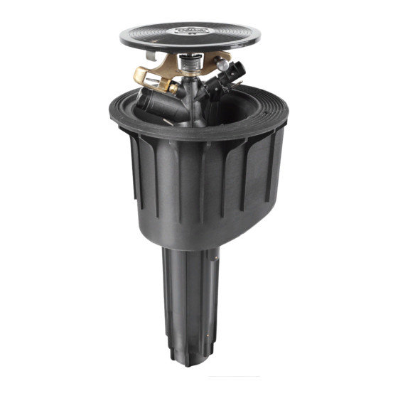
3. Description 3.1 Views TS120 Impact Sprinkler Securing screws Manual ON/OFF/Auto control module Cover for Cover Control Module compartment Housing Wire inlet openings Guide Housing Main water connection (1½” NPT) -
Page 6: Views Ts120 Impact Sprinkler With Vih And Turfcup
3.2 Views TS120 Impact Sprinkler Securing screw with VIH and TurfCup™ Manual ON/OFF/Auto control module Cover for Control Module compartment Securing screw 4” TurfCup™ (for natural turf) Cover for Control Module compartment Housing Wire inlet openings Guide Housing Main water... -
Page 7: Special Tools
Function Image RT19789 TS120 Assembly Key Assembly and disassembly of sprinkler head RT15745 TS120 10mm Socket Wrench Changing driving nozzle RT17623 TS120 Flushing Tool Safely Flushing laterals RT17839 Snap Ring Removal Hook Removing snap ring RT17843 TS120 Valve Insert Tool... -
Page 8: Technical Data
The pop-up sprinkler should be installed in accordance with the TS120 sprinkler installation diagram (see next page). In order to avoid any load pressure on the main line, use a recommended Toro adjustable swing joint or other pressure compatible flexible connection. -
Page 9: Ts120 Impact Sprinkler Installation Diagram
5.3 TS120 / TS121 Impact Sprinkler Installation Diagram Installation with Tee Connection: impact sprinkler standard position Toro TS120 or TS121 clamp valve box gravel packing and drainage Installation with Isolation Valve: impact sprinkler standard position clamp Toro solid cover valve... -
Page 10: Wiring
5.5 Wiring The laid 2-core wire is installed for the electrical connection of the TS120 Impact Sprinkler. The wire is pulled through the right or left opening on the bottom of the housing into the solenoid compartment. Use one of the drain holes to pull the control wires into the sprinkler. - Page 11 In this installation, the electrical connection is not exposed to the soil, but is protected inside the sprinkler and readily top-accessible. This simplifies any search for faults and any maintenance work can be carried out at any time without digging.
-
Page 12: Start-Up And Operation
6. Start-Up and Operation 6.1 Potential danger At start up, the impact sprinkler rises up out of the housing and builds up full pressure within about 5 seconds. The jet of water emitted can cause injury. For this reason, it is critical that all personnel and bystanders are clear of the irrigation area and are not in the path of the sprinkler’s nozzle opening. -
Page 13: Start-Up
6.2 Start-Up Procedure Be sure to follow the start-up procedure in order, a) to h). Steps a) Check electrical function: Before any water supply to the sprinkler is opened, activate the solenoid by means of the controller. An audible ‘clicking’ sound from the solenoid is indicative of its functioning properly. (The click is produced by movement of the plunger.) b) Ensure the manual control switch (located along the top cover of the rotor) is set to AUTO. -
Page 14: Arc Setting
6.3 Arc Setting • With this impact sprinkler the arc setting is infinitely adjustable between 30° and 330° and capable of a full circle 360°. • You can adjust the area to be watered by pulling or pressing on the relevant end of the top or bottom spring stop. -
Page 15: Shut-Down And Preparing For Winter
During times of possible frost, ensure there is no standing water in the sprinkler. • The TS120 Impact Sprinkler has an automatic drainage system. • The sprinkler has a discharge valve and will drain by gravity as long as water drains from the main pipe. -
Page 16: Maintenance And Repair Work
8 Maintenance and Repair Work An unexpected jet of water can cause serious injury. Prior to any maintenance or repair work ensure that the water supply is securely turned off. 8.1 Maintenance • Clean out the inside of the sprinkler housing using an industrial wet/dry vacuum cleaner or similar (as necessary). -
Page 17: Removing The Valve Insert
• Remove retaining ring in the housing bottom using removal hook tool (RT17839). • Engage hook into retaining ring tab and use a gentle twisting action to compress ring and remove. Retain ring for later. ring tab valve 8.4 Removing & Replacing the Valve Insert insert tool 1. - Page 18 4. To replace, screw the valve insert with the stainless steel disc onto the valve insertion tool. The chamfered surface of the stainless steel disc must point to the valve insert (as in, the larger surface facing up, the smaller surface down). Chamfer valve insert 5.
-
Page 19: Removal / Installation Of The Control Unit
8.5 Removal / installation of the control unit Ensure sprinkler is not under pressure. Removing the control unit • Lift the cover and secure the insert with a screw driver against snapping back. Locate the cover clip and pull clip to release. Remove cover. •... -
Page 20: Troubleshooting
9. Troubleshooting Observed Issue Cause Remedy Sealing disc worn out. Change sealing disc. Sprinkler not rotating, or Driving nozzle clogged. Unscrew driving nozzle and clean. rotating very slowly. Sprinkler not rotating at all. Minimum pressure of 45 psi not Increase pressure. reached. - Page 21 Notes...
- Page 22 Patent: www.ttcopats.com WARNING: Cancer and Reproductive harm – www.P65Warnings.ca.gov. For more information, please visit www.toro.com/CAProp65. © 2019 The Toro Company • Irrigation Division • www.toro.com Part Number 373-0947 Rev. C...