Table of Contents
Advertisement
Quick Links
Advertisement
Table of Contents

Related Manuals for Toro TS120


Summary of Contents for Toro TS120
- Page 1 TS120 Pop-up Impact Sprinkler Operating Manual...
-
Page 2: Table Of Contents
2.5 Dangers of failing to observe 9. Troubleshooting safety instructions 9.1 Sprinkler malfunctions 3. Description 3.1 Views TS120 Impact sprinkler with VIH 3.2 Views TS120 Impact sprinkler with VIH and TurfCup 3.3 Special tools 4. Technical data 5. Assembly, set-up and installation 5.1 Hazard warnings... -
Page 3: General
1. General We presume that you are experienced in the field of irrigation. We have therefore kept these instructions brief and included only the information that it is imperative for you to have to use this product. Any warranty claims can be accepted only if the sprinkler is used in accordance with these operating instructions and if any defect emerges within the warranty period. -
Page 4: Proper Use
2.2 Proper use The sprinkler is used for the even distribution of water onto lawns, green spaces and sports fields laid with natural or artificial grass. The water should be pre-cleaned and free of any coarse or fibrous contamination. The water and ambient temperatures must be below the limits specified in the technical data. 2.3 Clearly improper use •... -
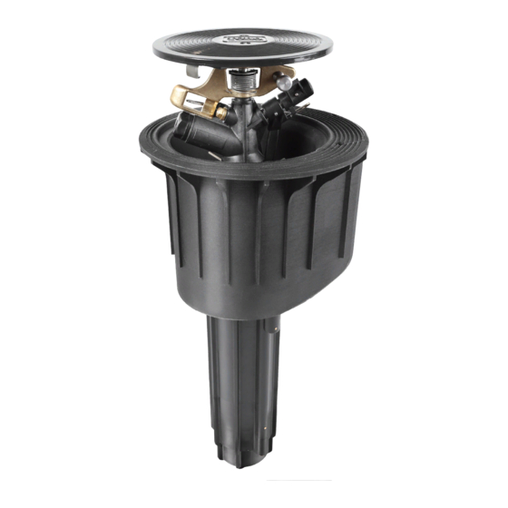
Page 5: Description
3. Description 3.1 Views TS120 Impact Sprinkler with VIH Securing screw Manual ON/OFF/Auto control module Cover for cable Cover compartment Housing Cable inlet openings Guide Housing Main water connection (1½”) -
Page 6: Views Ts120 Impact Sprinkler With Vih And Turfcup
3.2 Views TS120 Impact Sprinkler Securing screw with VIH and TurfCup Manual ON/OFF/Auto control module Cover for cable compartment Securing screw Turf cup Cover for cable compartment Housing Cable inlet openings Guide Housing Main water connection (1½”) -
Page 7: Special Tools
3.3 Special tools RT19789 TS120 Assembly Key Disassembly of sprinkler head and pipe axle RT15745 TS120 SW 10 Socket Wrench Changing driving nozzle DIN 3125 RT17623 TS120 Flushing Equipment Flushing pipes RT17839 Retaining Ring Removal Removing retaining ring Hook RT17843... -
Page 8: Technical Data
4. Technical data Recommended operating pressure 72.5 to 116 psi Permitted operating pressure 43.5 to 145 psi WARNING! The pressure at the sprinkler must not exceed 145 psi. Connection thread: G1½” NPT Liquids: Water Liquid temperature: 104° F max. Ambient temperature: 140°... -
Page 9: Ts120 Impact Sprinkler Installation Diagram
5.3 TS120 Impact sprinkler installation diagram... - Page 10 5.4 TS120 impact sprinkler installation diagram...
-
Page 11: Cabling
5.5 Cabling The laid 2-core cable is installed for the electrical connection of the TS120 impact sprinkler. The cable is pulled through the right or left opening on the bottom of the housing into the cable compartment. Possible location for pulling in the control cable into the sprinkler The DBR/Y-6 cable connector kit (article no.:... - Page 12 Put back the cables into the cable compartment and close the cover. The electrical connection is thus not exposed to the soil, but is instead protectively integrated inside the sprinkler and accessible again at any time. This simplifies any search for faults and any maintenance work can be carried out at any time without any earthwork.
-
Page 13: Commissioning And Operation
6. Commissioning and Operation 6.1 Potential danger When it starts up, the impact sprinkler rises up out of the housing and builds up full pressure within about 5 seconds. The jet of water emitted can cause injury. For this reason the following guidance must be followed when commissioning and operating the sprinkler: •... -
Page 14: Commissioning
6.2 Commissioning a) Check electrical function: Before any water supply to the sprinkler is opened, activate the coil by means of the controller. If you hear a ‘clicking’ sound from the coil, the electrics are working properly. (The click is produced by the movement of the armature.) b) Ensure that <Manual opening>... -
Page 15: Setting The Sector
6.3 Setting the sector With this impact sprinkler the sector setting is infinitely variable. You can adjust the area to be watered by pulling or pressing on the relevant end of the top or bottom spring stop. Setting the sector angle Infinitely variable setting is possible by pulling (not pressing) on the relevant end of WARNING! the top or bottom spring stop... -
Page 16: Decommissioning And Preparing For Winter
During times of possible frost please ensure that there is no standing water in the sprinkler. The TS120 impact sprinkler has an automatic emptying system. The sprinkler has a discharge valve and can thus be emptied by gravity. To do this, the water is let out at the deepest point of the main pipe, as a result of which the sprinkler empties itself. -
Page 17: Maintenance And Repair Work
8 Maintenance and repair work An unexpected jet of water can cause serious injury. Prior to any maintenance or repair work ensure that the water supply is securely turned off. 8.1 Maintenance • Clean out the inside of the sprinkler housing using an industrial vacuum cleaner or similar (as necessary). - Page 18 • Pull sprinkler module out of the housing. • Remove retaining ring in the housing bottom using removal hook RT17839. • Screw valve lifter in the housing base onto the valve and pull upwards. A few gentle hits may be necessary in order to take off the valve.
-
Page 19: Removing The Valve Insert
8.4 Removing the Valve Insert • Fitting the valve using valve lifter RT17843 (TC version RT17845). • Prior to fitting, check valve for any damage to the membrane. • Check for any dirt and clear away. • Screw the valve insert with the stainless steel disc onto the valve lifter. The chamfered surface of the stainless steel disc must point to the valve insert. -
Page 20: Removal / Installation Of The Control Unit
8.5 Removal / installation of the control unit Ensure sprinkler is not under pressure. Taking out the control unit • Lift the cover and secure the insert with a screw driver against snapping back. Then clip off the cover. • Unscrew all 3 locking screws (2 screws at TC version) and take off cable compartment cover. - Page 21 Fitting the control unit • When buying a replacement part, the control unit is supplied with plug-and-socket connections. Push hoses into plug-in grommets as far as they will go and ensure that the mounting ring springs back. • Screw in coil. •...
-
Page 22: Troubleshooting
9. Troubleshooting 9.1 Sprinkler malfunctions Malfunction Cause Remedy Sealing disc worn out Change sealing disc Sprinkler not rotating or only Driving nozzle clogged Unscrew driving nozzle and clean very slowly. Minimum pressure of 43.5 psi not Increase pressure Sprinkler not rotating at all. reached Sprinkler has poor jet Nozzle is blocked... - Page 23 Notes...
- Page 24 © 2017 The Toro Company • Irrigation Division • www.toro.com Part Number 373-0947 Rev. A...