
Related Manuals for ABB SensyTemp TSP


Summary of Contents for ABB SensyTemp TSP
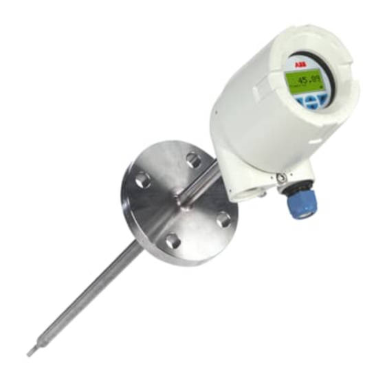
- Page 1 CI/TSP-EN SensyTemp TSP Commissioning Instructions Temperature Sensors SensyTemp TSP ® P R O F I PROCESS FIELD BUS B U S...
- Page 3 Tel.: +49 551 905-534 Fax: +49 551 905-555 CCC-support.deapr@de.abb.com © Copyright 2006 by ABB Automation Products GmbH Subject to change without notice This document is protected by copyright. It assists the user with the safe and efficient operation of the device.
-
Page 4: Table Of Contents
Protection types ............................13 4.1.6 Potential equalization ..........................14 4.1.7 Instrumentation .............................14 Temperature sensor connection without transmitter..................14 4.2.1 Resistance thermometers ........................15 4.2.2 Thermocouple ............................15 4.2.3 Installation in explosion risk area ......................16 Temperature sensor connection with transmitter ..................19 2 - EN SensyTemp TSP CI/TSP-EN... - Page 5 Contents Start-up ................................21 LC display ................................22 Appendix ................................22 Additional documents ...........................22 Supplementary documents...........................22 CI/TSP-EN SensyTemp TSP EN - 3...
-
Page 6: Safety
The secure isolation of contact-dangerous electrical circuits is only guaranteed when the connected devices fulfill the requirements of the DIN VDE 0106 T.101 (basic requirements for secure isolation). For secure isolation, run the supply lines separated from contact-dangerous electrical circuits or additionally isolate them. 4 - EN SensyTemp TSP CI/TSP-EN... -
Page 7: Operating Safety Information
VDE 0165/08.98 (=EN 60 079-14/1997 as well as IEC 60 079-14/1996) about the intrinsic safety of the interconnection is to be provided. An interconnection certificate for intrinsically safe electrical circuits is to be produced. CI/TSP-EN SensyTemp TSP EN - 5... -
Page 8: Configuration
After clamping the connection lines using a suitable tool (screwdriver, wrench), ensure that the connection heads are securely closed and sealed. Be sure to observe here that the sealing rings of the connection head are clean and undamaged. 6 - EN SensyTemp TSP CI/TSP-EN... -
Page 9: Insertion Depth
Insufficient mounting diameter For pipes with very small nominal diameters, an oblique insertion or insertion in an elbow pipe is recommended; whereby the thermowell tip must be positioned against the flow of the medium. Fig. 2 CI/TSP-EN SensyTemp TSP EN - 7... -
Page 10: Disassembly
The temperature sensors must be included in the potential equalization. 3.5.1 Intrinsic safety: ATEX II 1 G EEx ia IIC T6 ... T1, Zone 0, 1, 2 There are no additional specifics that must be observed for the mechanical installation. 8 - EN SensyTemp TSP CI/TSP-EN... -
Page 11: Dust-Ignition Proof: Atex Ii 1 D Ip6X T133
These may no longer be used if they have surface damage in the area of the ingnition penetration-proof seam or the connection head base. • Use only separate ignition-proof certified cable glands of a suitable ignition-proof type. ABB ships standard EEx d approved type ELFIT cable glands. CI/TSP-EN... -
Page 12: Intrinsic Safety And Hermetic Sealing: Atex Ii 1 G Ex Ia Iic T6 And Atex Ii 1/2 G Ex D Iic T6
Installation • Observe the cable gland approval and installation information. Observe the instruction manual 42/10-57 XU for the ABB supplied cable glands. • Check the line used with regards to suitability (type, actual line diameter, etc.). • Tighten the cable glands until the line is firmly enclosed by the sealing ring. -
Page 13: Electrical Connection
The documents belonging to the EC prototype inspection document are explicitly part of these operating instructions and must be mandatorily complied with. The temperature sensors must be included in the potential equalization. CI/TSP-EN SensyTemp TSP EN - 11... - Page 14 Field (Ex area) Control room (secure area) Fig. 3 A Transmitter B Feed separator / SPS input with feed Note Observe the “Technical specifications” and “Explosion-protection technical data” chapters (see data sheet and/or operating instructions). 12 - EN SensyTemp TSP CI/TSP-EN...
-
Page 15: Emc Suitable Cabling
2-, 3-, or 4-wire connection. Only one measurement circuit may be connected for the protection type EEx i for double measurement elements (z.B. 2 x Pt100). ABB transmitters are internally switched so that 2 measurement elements may also be connected since both elements are integrated into the same EEx I sensor circuit. -
Page 16: Potential Equalization
For use of double measurement circuits (2 x Pt100, 2 x thermocouple, 2 installed transmitters in the connection head), the sum of the voltages, currents and power may not exceed the electrical and thermal parameters. See chapter “Thermal data“ in the operating instructions. 14 - EN SensyTemp TSP CI/TSP-EN... -
Page 17: Resistance Thermometers
4-wire circuit Fig. 5 In accordance with EN 60751 (IEC 60751) Dual 2-wire circuit 3-wire circuit 4-wire circuit Fig. 6 yellow black W white 4.2.2 Thermocouple In accordance with EN 60584 Single Dual Fig. 7 CI/TSP-EN SensyTemp TSP EN - 15... -
Page 18: Installation In Explosion Risk Area
Only one measurement circuit may be connected for the protection type EEx i for double measurement elements (e.g. 2 x Pt100). ABB transmitters are internally switched so that 2 measurement elements may also be connected since both elements are integrated into the same EEx I sensor circuit. - Page 19 4.2.3.1. 4.2.3.3 Dust-ignition proof and intrinsic safety: ATEX II 1 D IP6X T133...T400 and ATEX II 1 G Ex ia IIC T6...T1, Zone 0, 1, 2, 20, 21, 22 See chapter 4.2.3.1. CI/TSP-EN SensyTemp TSP EN - 17...
- Page 20 See chapters 4.2.3.3 and 4.2.3.4. 4.2.3.6 ATEX Ex nA - Zone 2 and 22 Ex area Zone 2 and 22 Secure area Fig. 11 A Temperature sensor C Housing with IP 6X B Sensor connection wires D Transmitter 18 - EN SensyTemp TSP CI/TSP-EN...
-
Page 21: Temperature Sensor Connection With Transmitter
See ABB documentation 10/63-0.50. Fieldbus The instruction manual for the selected transmitter is included in the delivery by ABB. This information is additionally available for download on the Internet at www.abb.com/temperature. The technical data of the selected transmitter must be complied with. - Page 22 Hermetically sealed: ATEX II 1/2 G Ex d IIC T6 ... T4, Zone 1 Ex area Zone 1 Secure area Fig. 14 A Measuring inset in thermowell C EEx d approved housing (IP6X) with EEx d cable gland B Transmitter in connection head D Feed separator 20 - EN SensyTemp TSP CI/TSP-EN...
-
Page 23: Start-Up
The relevant safety and accident prevention regulations must be complied with. • The associated technical documentation for the operation of transmitters and indicator units is to be observed. The technical documentation is also available on the Internet at www.abb.com/temperature. CI/TSP-EN SensyTemp TSP EN - 21... -
Page 24: Lc Display
For information about using the LC display for parametrization of the transmitter, see the OI/TSP operating instructions. Appendix Note All documentation, declarations of conformity and certificates are available in the download area of ABB Automation Products GmbH. www.abb.com/temperature Additional documents • Operating Instructions (OI/TSP) •... - Page 28 ABB provides expert and comprehensive consulting services in ABB is continually improving its products. As a more than 100 countries worldwide. result, technical information in this document is subject to change. www.abb.com/temperature Printed in the Fed. Rep. of Germany (07.2006) ©...