
Related Manuals for ABB ABB-free@home WBI-S-1-xx-WL Series


Summary of Contents for ABB ABB-free@home WBI-S-1-xx-WL Series
- Page 1 2CKA001473B9425 14.02.2018 │ Product manual ABB-free@home ® WBI-S-1-xx-WL free@home window sensor, wireless BI-S-1-xx-WL free@home universal detector, wireless...
-
Page 2: Table Of Contents
Table of contents Table of contents Information on the manual .......................... 4 Safety ................................. 5 Information and symbols used ......................5 Intended use ........................... 6 Improper use ........................... 6 Declaration of conformity ........................ 7 Target group / Qualifications of personnel ..................7 Safety instructions ........................... - Page 3 Table of contents Update ..............................43 Maintenance ............................. 44 Cleaning ............................44 Notes ................................ 45 Index ................................ 46 Product manual 2CKA001473B9425 │3...
-
Page 4: Information On The Manual
If you pass the device on, also pass on this manual along with it. ABB accepts no liability for any failure to observe the instructions in this manual. If you require additional information or have questions about the device, please contact ABB or visit our Internet site at: www.abb.com/freeathome... -
Page 5: Safety
However, residual hazards remain. Read and adhere to the safety instructions to prevent hazards of this kind. ABB accepts no liability for any failure to observe the safety instructions. Information and symbols used The following Instructions point to particular hazards involved in the use of the device or provide... -
Page 6: Intended Use
Each use not listed in Chapter 2.2 “Intended use“ on page 6 is deemed improper use and can lead to personal injury and damage to property. ABB is not liable for damages caused by use deemed contrary to the intended use of the device. The associated risk is borne exclusively by the user/operator. -
Page 7: Declaration Of Conformity
Safety Declaration of conformity ABB herewith declares, that radio system type WBI-S-1-xx-WL and BI-S-1-xx-WL conform to directive 2014/53/EU. The complete text of the EU declaration of conformity is available at the following Internet address: WBI-S-1-xx-WL www.busch-jaeger-catalogue.com/ 6200-0-0067,article.html BI-S-1-xx-WL www.busch-jaeger-catalogue.com/ 6200-0-0068,article.html... -
Page 8: Safety Instructions
Safety Safety instructions Caution - risk of injury! An improper use of batteries can lead to the risk of sustaining injuries! Keep the batteries away from children. ■ In case of damaged batteries, avoid contact with skin, eyes and mucous ■... -
Page 9: Setup And Function
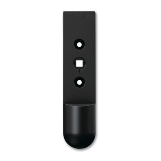
Setup and function Setup and function Window sensor Fig. 1: Product overview [1] Window sensor 6222/1 The status of windows (open, tilted and closed) can be monitored with the free@home window sensor, wireless. The window sensor is installed between the available window handle and the window frame. -
Page 10: Universal Detector
Setup and function Universal detector Fig. 2: Product overview [1] Universal detector 6222/2 With free@home universal detector, wireless the state (open and closed) of roof windows, skylights, doors and gates can be monitored. Special feature of universal detector: An additional connecting option for an external sensor (optional floating normally closed or open contact) is available. -
Page 11: Additional Product Features
Setup and function Additional product features No laying of cables is required for both types of detectors. Communication with the free@home system is carried out wireless. The devices are operated with a lithium battery (type CR2, 3 V). Material required for commissioning is supplied. -
Page 12: Scope Of Supply
Setup and function Scope of supply 3.5.1 Window sensor – Detector – 1 lithium battery (type CR2, 3 V) – Mounting accessories: Square extension, screws, adapter for cams. 3.5.2 Universal detector – Detector – 1 lithium battery (type CR2, 3 V) –... -
Page 13: Functions
Setup and function Functions 3.7.1 Window sensor and universal detector functions (via internal magnet contact) The following table provides an overview of the possible functions and applications of the device: Icon of the user Information interface Name: Window contact Type: Sensor Made available by: Window sensor + universal detector... - Page 14 Setup and function Icon of the user Information interface Name: Sensor (rocker) Control element for the control of free@home functions Name: Movement detector Sensor for movement- and brightness-dependent control of free@home functions Name: Window contact Signals "Window open" (Application: automatic deactivation of heating when the window is open) Name: Frost alarm Triggers a frost alarm (Application: Automatic retraction of the blinds, roller...
- Page 15 Setup and function The following table provides an overview of the possible functions and applications of the universal detector at the connection of an external sensor: Switching behaviour Sensor Icon Function Contact type type Description Normally open Push- contact button Normally open Switch contact...
- Page 16 Setup and function Switching behaviour Sensor Icon Function Contact type type Description Normally open After Setting switch- Movement contact time off delay for detector actuator Normally closed After sensor parameters contact time Normally open contact Window contact Normally closed contact Normally open contact Wind alarm...
-
Page 17: Description Of Functions
Setup and function Description of functions Note Special feature of universal detector: The device has two channels. One channel for the internal magnet contact and one channel for an external contact. The two channels are evaluated independently. 3.8.1 Rocker (only universal detector via connection of external sensor) The "Rocker"... - Page 18 Setup and function 3.8.4 Staircase lighting (only universal detector via connection of external sensor) If a push-button connected to the universal detector is to be used for switching staircase lighting, the "Staircase lighting sensor" function is to be selected. In the configuration of the associated switch actuator (to which the lamps of the staircase are connected), the "Switch-off delay"...
- Page 19 Setup and function 3.8.8 Frost, rain and wind alarm (only universal detector via connection of external sensor) These functions must be selected when connecting the relevant sensors, to protect blinds or roller blinds from damage. The channel of a detector configured with this function must be linked with one or several channels of a blind actuator (blind and roller blind or awning).
-
Page 20: Technical Data
Technical data Technical data Designation Value Power supply 1 x CR 2 (Lithium batteries); 3 V Typical battery service life 3 years Transmission frequency 2.400… 2.483 GHz Transmission protocol free@home wireless Maximum transmission power WL < 15 dBm (wireless) Protection IP20 Window sensor ■... -
Page 21: Dimensional Drawings
Technical data Dimensional drawings 4.2.1 Dimensional drawing of window sensor Note All dimensions are in mm. Fig. 3: Dimensions of window sensor [1] Maximum hight of fixing plate = 77 mm Additional specifications for window sensor: Square dimensions 7 mm Distance of fixing screws 43 mm Cams... - Page 22 Technical data 4.2.2 Dimensional drawing of universal detector Note All dimensions are in mm. Fig. 4: Dimensional drawing of universal detector Product manual 2CKA001473B9425 │22...
-
Page 23: Connection And Installation
Connection and installation Connection and installation Planning instructions NOTE Planning and application instructions for the system are available in system manual for ABB-free@home ® . This can be downloaded via www.abb.com/freeathome. Note Transmitter and receiver communicate via radio control. The transmission range depends on the structural conditions. -
Page 24: Installation
Connection and installation Installation 5.3.1 Requirements for window sensor installation Windows with attachments or decorative strips: Prior to the installation, check ■ whether there is a free space of 19 mm to all sides from the centre of the square hole (total width of the window sensor is 39 mm). - Page 25 Connection and installation 5.3.2 Window sensor installation Warning! – Risk of damage Damage to the window frame and window sensor due to incorrect mounting material – Use only the screws that are supplied for installing the window sensor. Observe the maximum length in order not to damage the window frame. Note Insert the battery only directly before programming starts.
- Page 26 Connection and installation Note The intermediate rings allow window handles with 10 mm cams and with 12 mm cams to be used. 10 mm 3. Insert the supplied intermediate rings. – Handles with 10 mm cams: Insert the supplied intermediate rings into the recesses of the window sensor.
- Page 27 Connection and installation 6. Turn the window handle to the side and fasten it with the supplied screws. Product manual 2CKA001473B9425 │27...
- Page 28 Connection and installation 5.3.3 Requirements for installing the universal detector Positioning the universal detector and magnetic contact: Fix the position of the universal ■ detector. The position of the supplied magnetic ■ contact can be fixed on both sides of the universal detector.
- Page 29 Connection and installation 5.3.4 Installation of universal detector Warning! – Risk of damage Damage to the universal detector due to incorrect mounting material – Use only the screws that are supplied for installing the universal detector. Note Insert the battery only directly before programming starts. The magnet and the universal detector can be either glued on or screwed on.
- Page 30 Connection and installation Screws: 1. Remove the cover of the battery compartment. 2. Screw on the universal detector and the magnet with the supplied screws. 3. Replace the cover of the battery compartment. Product manual 2CKA001473B9425 │30...
-
Page 31: Connection Of External, Floating Sensor On Universal Detector
Connection and installation Connection of external, floating sensor on universal detector Danger - Electric voltage! Install the device only if you have the necessary electrical engineering knowledge and experience. Incorrect installation endangers your life and that of the users of the ■... - Page 32 Connection and installation 2. To connect a sensor cable, break out the recess on the bottom of the device (A). 3. Connect the sensor cable to the terminal (C). 4. As strain relief the sensor cable can additionally be secured in the recess of the housing (B) with a cable tie.
-
Page 33: Commissioning
The devices must be parameterised for the use of additional functions. Note General information about commissioning and parameterization is available in the ABB-free@home ® system manual. Product manual 2CKA001473B9425... -
Page 34: Coupling Of Wireless Devices With The System Access Point
Commissioning Coupling of wireless devices with the System Access Point free@home wireless devices must first be coupled with the System Access Point before they can be used in a project. The devices exchange a security key during the coupling process. Communication between devices is carried out encrypted after coupling and they are firmly connected with the System Access Point. - Page 35 Commissioning Fig. 6: Inserting the batteries 4. Insert the battery into the device (A). – The LED (B) flashes briefly (battery function test). – The device is now in programming mode for 10 minutes. – The LED (B) now flashes as long as the programming mode is active. 5.
- Page 36 Commissioning 6.1.1 Resetting the wireless device to the factory settings A device that has already been programmed must be reset to enable it to be set again into programming mode. Fig. 7: Resetting to factory settings 1. Remove the battery (A) from the device and wait 30 seconds. 2.
-
Page 37: Allocation Of Devices And Definition Of Channels
Commissioning Allocation of devices and definition of channels Note Special feature of universal detector: The device has two channels. One channel for the internal magnet contact and one channel for an external contact. The two channels are evaluated independently. The devices connected to the system must be identified, i.e. they are allocated to a room according to their function and are given a practical name. - Page 38 Commissioning A pop-up window opens which lists all the devices that are connected to the bus and suitable for the selected application. Fig. 9: Pop-up window with the suitable devices Identification The device can be identified via the serial number. Identification via serial number Fig.
- Page 39 Commissioning Specifying a name Fig. 11: Specifying a name 1. Enter a name that is easy to understand and under which the application is to be displayed later, e.g. "Window Hall". 2. Press the tick at the bottom right. This takes over the entry. Note The settings of the device can be adjusted via the Web-based user interface of the System Access Point.
-
Page 40: Setting Options Per Channel
Commissioning Setting options per channel General settings and special parameter settings must be made for each channel. The settings are made via the "Devices" allocation function of the Web-based user interface of the System Access Point. Select device Fig. 12: Select device 1. - Page 41 Commissioning 6.3.1 Parameter settings of window sensor / universal detector Window sensor and universal detector (via internal magnet contact) [1] Changing the name [2] Deleting the channel [3] Switching of the actuator via the button Fig. 13: Sensor settings Universal detector (via connection of external sensor) [1] Changing the name [2] Deleting the channel [3] Switching of the actuator via the button...
-
Page 42: Links
Commissioning Links The sensors and actuators created via the "Devices" allocation function can be linked with each other. A detector can be linked with a second device, e.g. room temperature controller. When an open window is detected, the room temperature controller changes into "Frost protection" mode and reduces the set-point temperature to prevent unnecessary loss of energy. -
Page 43: Update
Update Update A firmware update is carried out via the Web-based user interface of the System Access Point. Product manual 2CKA001473B9425 │43... -
Page 44: Maintenance
Maintenance Maintenance The device is maintenance-free. In case of damage, e.g. during transport or storage), do not perform repairs. Once the device is opened, the warranty is void. Access to the device must be guaranteed for operation, testing, inspection, maintenance and repairs (according to DIN VDE 0100-520). -
Page 45: Notes
Notes Notes Product manual 2CKA001473B9425 │45... -
Page 46: Index
Index Index Add device ..........38 Notes ............46 Additional product features ......11 Allocation of devices ........38 Overview of types .......... 12 Batteries ............8 Parameter settings of window sensor / universal Battery service life ........11 Battery types ..........21 detector .......... - Page 47 Index Window contact ..........20 Window sensor ..........9 Window sensor and universal detector functions (via internal magnet contact) ......13 Window sensor installation ....... 26 Wireless battery devices Universal detector ............6, 12 Window sensor ............6, 12 Wireless device Factory settings ..............
- Page 48 A member of the ABB Group Notice We reserve the right to make Busch-Jaeger Elektro GmbH technical changes at all times as PO box well as changes to the contents of 58505 Lüdenscheid this document without prior notice. The detailed specifications agreed Freisenbergstraße 2...