
Related Manuals for ABB AP200 Series


Summary of Contents for ABB AP200 Series
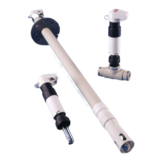
- Page 1 Rugged pH/Redox (ORP) Sensor Systems with User Guide IM/AP200_12 Rapid Temperature Response for Critical Processes AP200 Series...
- Page 2 Cert. No. Q 05907 As a part of ABB, a world leader in process automation technology, we offer customers application expertise, service and support worldwide. EN 29001 (ISO 9001) We are committed to teamwork, high quality manufacturing, advanced technology and unrivalled service and support.
-
Page 3: Table Of Contents
CONTENTS 1 DESCRIPTION ..............2 4 CALIBRATION ............... 13 1.1 Introduction .............. 2 4.1 Method ..............13 1.2 Systems ..............2 4.2 Buffer Solutions ............13 1.2.1 Typical Systems ........... 2 4.3 Redox (ORP Sensor) ..........13 1.2.2 AP120 Series Electrodes Used with Holders ........ -
Page 4: Description
1.2.2 AP120 Series Electrodes Used with Holders This manual describes the installation and maintenance of the AP121/11000 General process 0 to 14 pH, 0 to 100°C AP200 Series Process pH and Redox (ORP) Electrode Holder AP121/21000 High temperature 0 to 14 pH, 0 to 130°C Systems. -
Page 5: Mechanical Installation
2 MECHANICAL INSTALLATION 2.1 Installing the Systems 2.1.1 Model AP201 Insertion System – Fig. 2.1 This system is designed to mount directly into a pipeline or tank. Mounting adaptors are available: 7690 130 PPS Ryton™ R 1 in. adaptor 7690 128 R 1in. -
Page 6: Model Ap202 Inline System
…2 MECHANICAL INSTALLATION 2.1.2 Model AP202 Inline System – Fig. 2.2 This system is supplied with an inline tee-piece for mounting the system directly into a pipeline. Allow sufficient height above the system to enable the sensor to be withdrawn from the tee-piece. Dimensions in mm (in.) Minimum (3.94) -
Page 7: Model Ap203 Flanged Dip (Immersion) System
2 MECHANICAL INSTALLATION… 2.1.3 Model AP203 Flanged Dip (Immersion) System – Fig. 2.3 This system is designed to be installed over an unpressurized tank or channel. A sliding flange is supplied to enable adjustment of the immersion depth. A suitable mounting bracket or support must be supplied by the user. Dimensions in mm (in.) (3.94) (3.54) -
Page 8: Removing The Sensor Holder
…2 MECHANICAL INSTALLATION 2.2 Removing the Sensor Holder 2.2.1 Models AP201 Insertion and AP202 Inline Systems – Fig. 2.4 Open cover and detach cables and jetwash tubing (if fitted) from cap Twist cable shroud counter-clockwise and remove Unscrew sensor holder retaining nut and remove sensor holder from in-line adaptor Check O-ring is in position,... -
Page 9: Model Ap203 Flanged Dip (Immersion) System
2 MECHANICAL INSTALLATION… 2.2.2 Model AP203 Flanged DIp (Immersion) System – Fig. 2.5 Open cover and detach cables and jetwash tubing (if fitted) from cap Unscrew sensor guard from dip tube ( see Note below Notes. • Before refitting the sensor guard, clean and regrease the threads and O-ring. -
Page 10: System Assembly
…2 MECHANICAL INSTALLATION 2.3 System Assembly – Fig 2.6 Close cover Note. Model AP201 shown. When assembling Models AP202 and AP203, refit the Tee piece to the sensor holder (AP202) or the sensor guard to the dip tube (AP203) – see Figs. 2.4 and 2.5. Clip cables and jetwash tube (if required) into slots in protective cover... -
Page 11: Jetwash System
2 MECHANICAL INSTALLATION… 2.4 Jetwash System – Figs 2.6 to 2.8 Cleaning Solutions The spray jet tube is available in 316 stainless steel. Some typical cleaning solutions are: Note. Installation must be carried out in accordance with local water company and council bylaws. The jetwash system enables automatic cleaning of both the n i l measuring element and the reference junction by spraying either... -
Page 12: Jetwash System Assembly
…2 MECHANICAL INSTALLATION 2.5 Jetwash System Assembly – Fig. 2.9 The system is supplied with a blanking plug fitted to the jetwash tubing connector. If the jetwash system is to be used, remove the plug and fit the jetwash supply tube as shown in Fig. 2.9. Note. -
Page 13: Electrical Installation
3 ELECTRICAL INSTALLATION 3.1 Analyzer Connections – Fig. 3.1 3.2 Shortening the Connection Cable – Fig. 3.2 System cable connections are identified in Fig. 3.1 to enable The connection cable is supplied in various standard lengths. If connection to the appropriate terminal on the analyzer. it is necessary to shorten the cable, prepare the cable ends as shown in Fig. -
Page 14: Extending The Connection Cable
…3 ELECTRICAL INSTALLATION 3.3 Extending the Connection Cable – Fig. 3.3 3.4 Jetwash System Connections If it is necessary to extend the cable, a suitable junction box and The electrical supply to the jetwash system pump or solenoid the correct length of 6-core cable are required. Connect the valve is connected to the analyzer relay used for automatic junction box as shown in Fig. -
Page 15: Calibration
4 CALIBRATION 4.1 Method 4.2 Buffer Solutions When the electrode system has been correctly connected and Recommended buffer solutions are shown in Table 4.1. all electrical connections made to the associated pH analyzer, the system is ready for calibration by immersing the sensor (using suitably sized beakers) either: a) in a calibration solution (buffer) of known pH value for a single-point calibration,... -
Page 16: Maintenance
5 MAINTENANCE 5.1 General Cleaning 5.2 Fault Finding Listed below are some common symptoms of sensor malfunction together with possible cures. Warning. Close all isolating valves before removing an electrode from a flow line. Short scaling ( Low Slope ) or sluggish response 1) Glass sensor membrane dirty or coated –... -
Page 17: Specification
6 SPECIFICATION All Systems AP203 Immersion (Dip) System Materials Materials Shaft and cap Polypropylene Guard, shaft and cap Polypropylene Sensor body Ryton™ PPS Maximum Temperature 90°C (194°F) Ground rod/Spray tube 316 Stainless steel Maximum Pressure Jet-wash facility Not applicable Non-return function Integral one-way valve Process Connections Spray tube connection... -
Page 18: Spares
7 SPARES 7.1 Model AP201 Insertion System – Fig. 7.1 . n i i t c . n i . n i o t i i t c £ r a l o t i e l r , d i i v r s i r , e l... -
Page 19: Model Ap202 Inline System
7 SPARES… 7.2 Model AP202 Inline System – Fig. 7.2 f l e n i l i t c £ . n i i t c . n i . n i o t i r a l o t i t i l i v r s i r... -
Page 20: Model Ap203 Flanged Dip (Immersion) System )
…7 SPARES 7.3 Model AP203 Flanged Dip (Immersion) System – Fig. 7.3 Fig. 7.3 Model AP203 Flanged Immersion (Dip) System Spares... - Page 21 7 SPARES …7.3 Model AP203 Flanged Dip (Immersion) System – Fig. 7.3 i t c i t c f l e £ o t i i t c e l r , d i i t c , e l , d i i v r s i r...
- Page 22 NOTES...
- Page 23 – Manufacturing United Kingdom – Metals and Minerals – Oil, Gas & Petrochemical ABB Limited – Pulp and Paper Tel: +44 (0)1453 826661 Fax: +44 (0)1453 829671 Drives and Motors United States of America • AC and DC Drives, AC and DC Machines, AC Motors to 1kV ABB Inc.
- Page 24 ABB has Sales & Customer Support The Company’s policy is one of continuous product improvement and the right is reserved to modify the expertise in over 100 countries worldwide information contained herein without notice. Printed in UK (06.06) www.abb.com © ABB 2006 ABB Limited ABB Inc.