Table of Contents
Advertisement
Quick Links
Advertisement
Table of Contents

Related Manuals for Boca Systems LEMUR-FDIO


Summary of Contents for Boca Systems LEMUR-FDIO
- Page 1 LEMUR - FDIO FLIGHT STRIP PRINTER USER MANUAL July 11, 2018...
- Page 2 Revision Listing Date Comments 1/10/2018 Released for Production Updated photos on pages 6/18/2018 4,5,6,12,17,22,29,31,34,40,41 & 43 7/11/2018 Updated default setting in section 6.0...
-
Page 3: Table Of Contents
9.1 Interfaces and Pinouts ................... 37 9.2 General ......................38 10.0 Spare Parts List with Visual References ............. 39 11.0 General Printer Testing Guidelines ..............44 11.1 Lemur-FDIO Flight Strip Printer Setup ............46 11.2 Firmware Test Plan ..................49 12.0 Troubleshooting Guide ..................50... - Page 4 List of Addendum Addendum A - Purchased Components - Performance Data / Data Sheets Addendum B - Mechanical Drawings and Parts List Addendum C - Wiring Diagrams Addendum D - Schematics...
-
Page 5: Fcc Notice
FCC NOTICE NOTE: The equipment has been tested and found to comply with the limits for a class B digital device, pursuant to part 15 of the FCC rules. These limits are designed to provide reasonable protection against harmful interference when the equipment is operated in a commercial environment. This equipment generates, uses, and can radiate radio frequency energy and, if not installed and used in accordance with the instruction manual, may cause harmful interference to radio communications. -
Page 6: Introduction
1.0 Introduction The BOCA Lemur-FDIO is a direct thermal flight strip printer. This device is capable of connecting to the FAA host computer, printing, cutting and stacking Domestic and Oceanic flight strips. This manual will provide the user with general information regarding printer set-up, operational instructions and detailed technical information. -
Page 7: Important Safety Information
3.0 Important Safety Information WARNING: The appearance of this symbol indicates the proximity of an exposed high voltage area. Please follow all directions carefully for your personal safety. You must read the following safety information carefully before working on the printer. As a safety precaution, all service to the printer should be done by qualified persons with... -
Page 8: Printer Tour
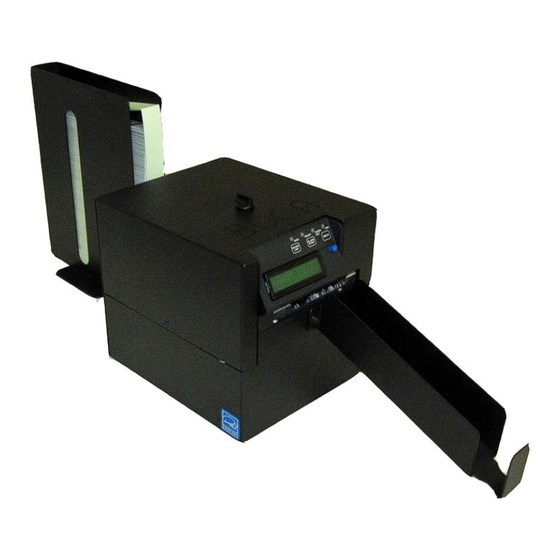
4.0 Printer Tour The following photos are presented for the purpose of familiarizing the user with the Lemur-FDIO Flight Strip Printer. Figure 1 – Lemur-FDIO Flight Strip Printer and accessories Input Hopper Lemur- FDIO Flight Strip Printer Output Hopper... - Page 9 Figure 2 – Front View...
- Page 10 Figure 3 – Control Panel LED Indicator Lights Selection Buttons LCD Display LCD Dimmer...
- Page 11 Figure 4 – Rear View ON/OFF Power A/C Power Receptacle USB Connector RS422 Connector Ethernet Connector...
- Page 12 Figure 5 – Top View Cover Removed...
- Page 13 Figure 6 – Entry Paper Guide Insert Strips Here...
-
Page 14: Installation And Flight Strip Loading
Load flight strips into the input hopper and locate the hopper at a distance behind the printer to allow for the smooth feed of strips to the entrance guide on the Lemur-FDIO. Ensure that the stack of strips is loaded into the hopper so that the arrow (on the bottom of the strip), which indicates feed direction, is loaded into the printer accordingly. - Page 15 Verify that the printer is configured to use the correct flight strip type. If not, remove the cover of the Lemur-FDIO and adjust the adjustable paper guide by hand (see section 7.1.5) so that the flight strip is guided properly, without making it too tight. You will also need to use the control panel to configure the print format, as described in the Programming Guide.
-
Page 16: Control Panel Options
6.0 Control Panel Options The Lemur-FDIO allows the user to adjust various printer options through the front control panel. ON/OFF LINE: Scrolls MENU: Selects proper through choices in menu topic (baud rate, individual menu topics cut count, etc.) BLANK STRIP: Enters and saves new values The printer has four LED lights on the control panel. - Page 17 To access and view the FACTORY MENU, follow these steps: 1. Flight strips should be loaded into the printer with the printer powered on. 2. Press and hold the MENU button first, and while continuing to keep the MENU button depressed, press and hold the ON/OFF LINE button for approximately for about 3 seconds.
- Page 18 The chart below lists the present menu topics. These topics are subject to change. OPERATOR MENU STRIP SELECTION? INC CUT1 COUNT? DEC CUT1 COUNT? INC TOP ADJ? DEC TOP ADJ? PRINT INTENSITY? USB? BAUD RATE? USB DEVICE TYPE? MINI/MICRO? ETHERNET? PRINT SPEED? IP ADDRESS? DIAGNOSTIC MODE?
- Page 19 MINI/MICRO? Defines if printer has a cutter. Factory set do not modify. MINI cutter (default) MICRO no cutter PRINT SPEED? Controls the print speed and the print quality. Printer should not be run at a print speed of 0 as it may cause ticket jams.
- Page 20 DEC MINIREV? Allow horizontal positioning of the flight strip data within the printable area of flight strip to be adjusted. This control is primarily used to adjust the print position left at the factory and is not normally needed during normal printer operation.
-
Page 21: Maintenance And Adjustments
7.0 Maintenance and Adjustments Your Lemur-FDIO flight strip printer is solidly constructed and has been designed for high volume use. It requires minimal care to provide maximum service. WARNING: The appearance of this symbol indicates the proximity of an exposed high voltage area. Please follow all directions carefully for your personal safety. -
Page 22: Thermal Print Head (Cleaning & Replacement)
7.1.1 Thermal Print Head (Cleaning & Replacement) The following needs to be done with the printer powered off and unplugged from the AC source. 1. Remove the cover of the printer to gain access to the print assembly area. 2. Lift up on the cam lock assembly (located above the head mounting plate) to remove pressure from the thermal head. - Page 23 6. Clean the thermal print head surface (the side that makes contact with the paper) with isopropyl alcohol & paper towel. 7. Install the head mounting plate by reversing the above procedures. Make sure the print head mounting plate tabs are in the back slot of the print cage slots. Back Slot 8.
-
Page 24: Cut Opto
7.1.2 Cut Opto Assembly The purpose of this device is to sense the black mark located on the rear of the flight strip in order to determine a cut position. OPTO EYE The cut position may be adjusted via the control panel (see section 6.0). If you are not able to get the desired cut position, make sure your ticket stock is being loaded correctly into the printer and BLANK FLIGHTS STRIPS menu setting matches the stock being used. -
Page 25: Platen (Rubber Driver Roller)
7.1.4 Platen (Rubber Driver Roller) The Platen (rubber drive roller) should be cleaned once a year to prevent paper dust from building up on the roller. (NOTE: The platen may require more frequent cleaning in dusty environments or when using inferior flight strip stock.) The following needs to be done with the printer powered off and unplugged from the AC source Remove the print head mounting plate from the printer as shown in section 7.1.1. -
Page 26: Cutter Assembly
7.2 Cutter Assembly The cutter assembly is a fully integrated cutter knife mechanism powered by a stepper motor. The cutter requires no adjustments and is rated for approximately 750,000 cuts. Please be aware of the following. The cutter area where the tickets exit the printer should be blown out with air periodically to prevent debris from building up inside the cutter area. -
Page 27: Removal & Replacement Of Major Assemblies
8.0 Removal & Replacement of Major Assemblies... -
Page 28: Logic Board Removal/Replacement
8.1 Logic Board Removal/Replacement The printed circuit boards used in this product have been manufactured using surface mount technology. These printed circuit boards cannot be effectively repaired in the field. WARNING: All Service must be done with the printer off and the AC cord unplugged from the printer. - Page 29 4. Denote where all the cables are plugged into the logic board. Gently unplug the cables from logic board. 5. Remove four 3/16 hex head screws shown in the below photo. 6. Gently remove logic board from cabinet. 7. Install the board by reversing the above steps.
-
Page 30: Cut Opto Removal/Replacement
8.2 Cut Opto Removal/Replacement Please make sure the printer is powered off and unplugged from the AC source. 1. Remove the print head mounting plate from the printer. See section 7.1.1. 2. Loosen the four 3/16” hex head screws that holds the extended paper guide cover in place and slide the cover off. -
Page 31: Load Sq Opto Removal/Replacement
8.3 Load SQ Opto Removal/Replacement Please make sure the printer is powered off and unplugged from the AC source. Remove the electronics cover from the printer. See section 8.1. Remove the four Phillips head screws that hold the print cage onto the electrical cover. Once the screws have been removed the electrical cover may be gently tilted away from the print cage to gain access to the Load SQ Opto. - Page 32 There is a washer just under the black Load SQ Opto mounting bracket that must not be removed. When installing the opto back in place make sure the tab on the black opto mounting bracket lines up with the slot in the paper guide. Installed the flat washer and 1⁄4” nut back in place then tighten.
-
Page 33: Control Panel Removal/Replacement
8.4 Control Panel Removal/Replacement Please make sure the printer is powered off and unplugged from the AC source. 1. Remove the three 3/16” hex head screws that hold the control panel in place. 2. Cut the zip tie holding the cable in place and gently unplug the keyed grey ribbon from the control panel. -
Page 34: Power Switch Board Removal/Replacement
8.5 Power Switch Board Removal/Replacement Please make sure the printer is powered off and unplugged from the AC source. Remove the cover from the printer. Gain access to the power switch board by removing the electronics cover. See section 8.1. Unplug the two cables that are connected to the power switch board and remove the one 3/16”... -
Page 35: Platen Removal/Replacement
8.6 Platen Removal/Replacement Please make sure the printer is powered off and unplugged from the AC source. Remove the cover from the printer. Remove the printer head mounting plate/ print head from the printer. See section 7.1.1. Loosen the electronics cover by removing the screws that hold it in place. See section 8.1. Remove the four Phillips head screws that hold the cutter assembly in place. - Page 36 Loosen the four Phillips head screws that hold the stepper motor in plate. Move the stepper motor forward to enable the drive belt to be removed. Remove the grip ring from the platen shaft. Grip Ring The platen may be removed by grabbing onto white pulley and sliding it out towards that side. On the pulley side you will want to make sure the bushing comes out of the print cage.
- Page 37 Install the drive belt back on the pulleys. Slide the stepper motor back just enough to take up the belt tension and tighten the four Philip head screws. Grab onto the driver belt and turn it a few times. You want to make sure the platen still moves freely.
-
Page 38: Cutter Assembly Removal/Replacement
8.7 Cutter Assembly Removal/Replacement Please make sure the printer is powered off and unplugged from the AC source. Remove the cover from the printer. Loosen the electronics cover by removing the screws that hold it in place. See section 8.1. Remove the four Phillips head screws that hold the cutter assembly in place. - Page 39 Connect the wires to the replacement cutter assembly and zip tie in place. Take care to make sure the wires are properly connected to their respective sensors. See photo below. Secure the control panel back onto the cutter assembly. Install the cutter assembly back onto the print cage and make sure the ground wire is attached back on as shown in step #4.
-
Page 40: Specifications
9.0 Specifications... -
Page 41: Interfaces And Pinouts
9.1 Interfaces and Pinouts Please refer to figure 4 for location of interface connectors. RS 422 (DB25F Connector) Pin 1.....frame ground Pin 7.....signal ground Pin 15...negative input Pin 17...positive input Pin 19..negative transmit Pin 25 ..positive transmit USB 2.0 Compliant Pin 1.....VCC (+5V) Pin 2.....D- (Data -) Pin 3....D+ (Data+) -
Page 42: General
9.2 General Print Method: Direct thermal Print Speed: 8 inches per second (maximum) Resolution: 300 dpi Size: 7.82 H x 7.32 W x 8.94 L (not inclusive of input and output hoppers) Weight: 7.0 pounds Media type: thermal flight strips (fanfolded) Media thickness: .007 inch Media Width: 1.0 to 1.33 inches Positioning: optical detector sensing black mark... -
Page 43: Spare Parts List With Visual References
10.0 Spare Parts List with Visual References Item Part Number Description 422590-C Stepper Motor & 20 drive pulley P50-1003 Drive Belt, 102T (for 300dpi) 423760-FSP-1-C Platen complete 424008-C Cutter Assembly (BC5) Complete 423793 Energy Star Decal 422557-25 Cable, Thermal Head 423842Z-P1 Electronics Cover, PS46... - Page 44 Above photo shows the Print Cage Pulley Cover removed...
-
Page 48: General Printer Testing Guidelines
11.0 General Printer Testing Guidelines The following information is provided for reference only. It is used only by Boca technicians for the configuration and testing of our printers. Before you test the printer, you will need to pull its production folder. The folder contains all information concerning the printer in question. - Page 49 Printer properly loads and ejects the tickets. Run printer off the host computer. The best way to do this is to run 15 tickets from parallel port, 15 tickets from USB port and 15 tickets from the serial port. When running the serial port, make sure the printer runs out of tickets during the run and you do not lose any tickets when the stock is reloaded.
-
Page 50: Lemur-Fdio Flight Strip Printer Setup
11.1 Lemur-FDIO Flight Strip Printer Setup The following information is provided for reference only. It is used only by Boca technicians for the configuration and testing of our printers 1. Set USB DEVICE TYPE to HID. 2. Connect the printer via the USB interface port. - Page 51 You should see the below in the message window area. 12. With the printer powered off holding down the MENU and ON/OFF LINE buttons. Power up the printer and hold buttons until printer shows FACTORY MENU. Change STRIP SELECTION to DOMESTIC. Use the DOMESTIC. Pressing the BLANK STRIP button only will cause the below printout.
- Page 52 23. Affix the two tags onto the bottom of the printer and blue EnergyStar sticker as shown in the below photos. OCEANIC DOMESTIC HALF DOMESTIC...
-
Page 53: Firmware Test Plan
11.2 Firmware Test Plan... -
Page 54: Troubleshooting Guide
12.0 Troubleshooting Guide This troubleshooting guide is intended to assist the user or support person in the fault isolation of typical problems. As a safety precaution, all service to the printer should be done by qualified persons with power off and the AC cord unplugged from the printer. Following any procedure requiring the removal of covers and/or doors, please verify that they have been properly attached and fastened prior to operating the printer. - Page 55 TICKET CUT IN THE WRONG LOCATION a. Make sure the flight strip is being loaded into the printer the correct way. (See Sect 5.0). b. Make sure the STRIP SELECTION is set to match the type of flight strip that is being loaded in the printer.
- Page 56 9. POOR PRINT OUT (white voids in print out) a. Clean print head. (See Sect 7.1.1) b. Replace thermal head. (See Sect 7.1.1) c. Printer needs to be serviced. NO PRINT OUT a. Try a different stack flight strips. b. Make sure the cam lock lever is fully locked in the closed position. (See Sect 7.1.1) c.
Need help?
Do you have a question about the LEMUR-FDIO and is the answer not in the manual?
Questions and answers