Table of Contents
Advertisement
Quick Links
Download this manual
See also:
Operator's Manual
Register at www.Toro.com.
Original Instructions (EN)
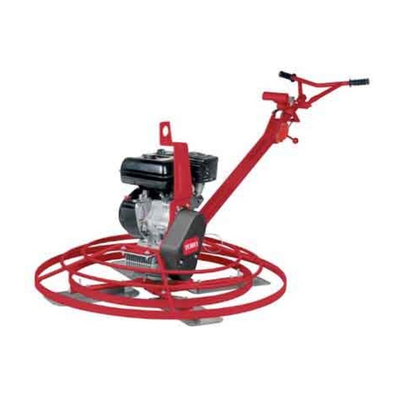
PT-36, PT-36PP, PT-46, and
PT-46PP Power Trowels
Model No. 68048—Serial No. 404320000 and Up
Model No. 68049—Serial No. 404320000 and Up
Model No. 68050—Serial No. 404320000 and Up
Model No. 68051—Serial No. 404320000 and Up
Form No. 3429-787 Rev A
*3429-787* A
Advertisement
Table of Contents

Related Manuals for Toro PT-36PP


Summary of Contents for Toro PT-36PP
- Page 1 Form No. 3429-787 Rev A PT-36, PT-36PP, PT-46, and PT-46PP Power Trowels Model No. 68048—Serial No. 404320000 and Up Model No. 68049—Serial No. 404320000 and Up Model No. 68050—Serial No. 404320000 and Up Model No. 68051—Serial No. 404320000 and Up *3429-787* A Register at www.Toro.com.
-
Page 2: Figure
Other states Read this information carefully to learn how to operate or federal areas may have similar laws. Genuine Toro and maintain your product properly and to avoid spark arresters are approved by the USDA Forestry injury and product damage. -
Page 3: Table Of Contents
Contents This manual identifies potential hazards and has safety messages identified by the safety alert symbol (Figure 2), which signals a hazard that may cause Safety ............... 4 serious injury or death if you do not follow the Safe Operating Practices........4 recommended precautions. -
Page 4: Safety
Safety – Extinguish all cigarettes, cigars, pipes, and other sources of ignition. – Use only an approved container Improper use or maintenance by the operator or owner can result in injury. To reduce the potential for injury, – Do not remove the fuel cap or fill the fuel tank comply with these safety instructions and always pay while the engine is running or hot. - Page 5 Keep nuts and bolts tight. Keep equipment in good condition. • Stop and inspect the equipment if you strike an object. Make any necessary repairs before restarting. • Use only genuine Toro replacement parts to ensure that original standards are maintained.
-
Page 6: Safety And Instructional Decals
Safety and Instructional Decals Safety decals and instructions are easily visible to the operator and are located near any area of potential danger. Replace any decal that is damaged or missing. decal93-9084 93-9084 1. Lift point 2. Tie-down point decal125-4934 125–4934 1. -
Page 7: Product Overview
Product Overview g019519 g021560 Figure 4 1. Lifting point 5. Sediment cup 2. Fuel-tank cap 6. Recoil-starter handle 3. Choke lever 7. Engine On/Off switch 4. Fuel valve Controls Recoil-Starter Handle Pull the recoil-starter handle to start the engine (Figure Fuel Valve Close the fuel valve when transporting or storing the machine... - Page 8 engine. Rotate the On/Off switch to the Off position to shut off the engine. Throttle Handle Pull the throttle handle (Figure 3) to increase the engine speed, and push the handle to decrease the engine speed. Turn the handle clockwise to lock the throttle at a specific speed.
-
Page 9: Specifications
API service category SJ or higher and expand its capabilities. Contact your Authorized Service Dealer or Distributor or go to www.Toro.com Models Crankcase Capacity for a list of all approved attachments and accessories. -
Page 10: Checking The Gearcase Oil Level
g021590 g019746 Figure 10 Figure 9 1. Fill port 3. Oil-level upper limit 2. Dipstick 4. Oil-level lower limit If the oil level is not correct, refer to Servicing the Gearcase Oil (page 17). Unscrew the dipstick and wipe the end clean (Figure Cleaning Debris from the Slide the dipstick fully into the fill port... -
Page 11: Adding Fuel
DANGER In certain conditions, fuel is extremely flammable and highly explosive. A fire or explosion from fuel can burn you and others and can damage property. • Fill the fuel tank outdoors, in an open area, when the engine is cold. Wipe up any fuel that spills. - Page 12 DANGER In certain conditions during fueling, static electricity can be released causing a spark which can ignite the fuel vapors. A fire or explosion from fuel can burn you and others and can damage property. • Always place fuel containers on the ground away from your vehicle before filling.
-
Page 13: Starting The Engine
Filling the Fuel Tank Starting the Engine Set the throttle to full speed and set the Models Fuel Tank Capacity Dyna-Clutch lever to the S position. 68048 and 68049 3.1 L (0.82 US gallons) Move the engine switch to the O position and 68050 and 68051 5.3 L (1.40 US gallons) -
Page 14: Maintenance
Maintenance Recommended Maintenance Schedule(s) Maintenance Service Maintenance Procedure Interval • Change the engine oil. After the first 25 hours • Check the engine-oil level. • Check the gearcase oil level. • Clean debris from the air cleaner and engine. Before each use or daily •... -
Page 15: Lubrication
Lubrication Engine Maintenance Lubricating the Blade Arms Servicing the Air Cleaner Service Interval: Before each use or daily Service Interval: Before each use or daily—Inspect the air cleaner elements. Grease Type: General-purpose grease. Every 50 hours—Clean the air filter elements. Clean around each grease fitting with a rag and Clean them more frequently in dusty operating lift the plastic cap off each grease fitting. -
Page 16: Servicing The Engine Oil
Remove the cover (Figure 16 Box B). Note: Be careful to prevent dirt and debris from falling into the base. Remove the foam and paper elements from the base (Figure 16 Box C). Remove the foam element from the paper g019679 element (Figure 16... -
Page 17: Servicing The Gearcase Oil
Remove the dipstick (Figure 9) and slowly pour oil into the fill hole until the oil is between the upper and lower fill marks on the dipstick. Install and secure the dipstick. Wipe up any spilled oil. Servicing the Gearcase Oil Service Interval: Every 150 hours g013375 Figure 17... -
Page 18: Servicing The Spark Plug
Servicing the Spark Plug Apply thread-sealing compound to the threads of the plug. Service Interval: Every 100 hours—Inspect and Install and tighten the plug until it is secure, and adjust the spark plug; replace it if return the machine to an upright, level position. necessary. -
Page 19: Belt Maintenance
Belt Maintenance Removing the Belt Guard Remove the 2 hex-washer head bolts (5/16 x 1 inch) that secure the belt guard to the belt-guard Checking the Belt, Pulley bracket (Figure 22). Alignment, Belt Tension, and Belt-Guide Gap Service Interval: Every 40 hours Remove the belt guard;... -
Page 20: Removing The Belt
Removing the Belt Aligning the Pulleys Place a straight-edge ruler across the engine Position the machine on a level surface, place pulley and the gearbox pulley (Figure 24). the Dyna-Clutch lever in the S position, shut off the engine, and disconnect the spark-plug wire. -
Page 21: Adjusting The Belt Guide
Note: If the blades continue to rotate when the Dyna-Clutch is in the S position, there is too much tension on the clutch cable. Shut off the engine and repeat step until the blades do not rotate when the engine is running and the Dyna-Clutch is in the S position. -
Page 22: Controls System Maintenance
Adjusting the ProPitch Controls System Linkage Rod Maintenance Set the Dyna-Clutch lever to the Stop position, shut off the engine, and wait for all moving parts Adjusting the Tilt Knob to stop. Set the Dyna-Clutch lever to the Stop position, Disconnect the wire from the spark plug. -
Page 23: Testing The Dyna-Clutch Lever
Testing the Dyna-Clutch Lever Testing the Dyna-Clutch Operation Ensure that the area is clear of any debris or bystanders before beginning the testing procedures. Start the trowel, engage the Dyna-Clutch lever, and run the machine for a few moments. Move the Dyna-Clutch lever to the Stop position. Watch the blades for any sign of continued g025040 rotation. - Page 24 g019517 Figure 32 1. Ruler 3. Second blade 2. Spot on floor from first measurement Compare the 2 measurements. If the height of the second blade is not within 0.8 mm (1/32 inch) of the height of the first blade, adjust the second blade.
-
Page 25: Adjusting The Blade Arms
Adjusting the Blade Arms Storage Adjust the blade arms if the machine still shakes Set the Dyna-Clutch lever to the Stop position, excessively after the blades have been adjusted. shut off the engine, and disconnect the Place the machine on a flat surface. spark-plug wire. -
Page 26: Troubleshooting
Troubleshooting Problem Possible Cause Corrective Action The trowel blade turns when the recoil is 1. The clutch is engaged. 1. Disengage the Clutch. pulled. 2. The clutch is not properly adjusted. 2. See Adjusting the Dyna-Clutch Lever. 3. The belt guide bracket is bent. 3. - Page 27 Notes:...
- Page 28 While the exposure from Toro products may be negligible or well within the “no significant risk” range, out of an abundance of caution, Toro has elected to provide the Prop 65 warnings. Moreover, if Toro does not provide these warnings, it could be sued by the State of California or by private parties seeking to enforce Prop 65 and subject to substantial penalties.