Table of Contents
Advertisement
Quick Links
Preface
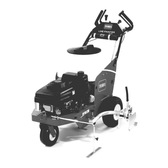
The purpose of this publication is to provide the service
technician with information for troubleshooting, testing
and repair of major systems and components on the
Line Painter 1200.
REFER TO THE OPERATOR'S MANUALS FOR OP-
ERATING,
MAINTENANCE
INSTRUCTIONS. Space is provided in Chapter 2 of this
book to insert the Operator's Manuals and Parts Cata-
logs for your machine. Replacement Operator's Manu-
als are available on the internet at www.toro.com or by
sending complete Model and Serial Number to:
The Toro Company
Attn. Technical Publications
8111 Lyndale Avenue South
Minneapolis, MN 55420
The Toro Company reserves the right to change product
specifications or this publication without notice.
AND
ADJUSTMENT
E The Toro Company – 2005, 2007
Service Manual
Line Painter 1200
This safety symbol means DANGER, WARNING,
or CAUTION, PERSONAL SAFETY INSTRUC-
TION. When you see this symbol, carefully read
the instructions that follow. Failure to obey the
instructions may result in personal injury.
NOTE: A NOTE will give general information about the
correct operation, maintenance, service, testing or re-
pair of the machine.
IMPORTANT: The IMPORTANT notice will give im-
portant instructions which must be followed to pre-
vent damage to systems or components on the
machine.
Part No. 05144SL Rev. A
Advertisement
Chapters
Table of Contents
Troubleshooting

Related Manuals for Toro Line Painter 1200


Summary of Contents for Toro Line Painter 1200
- Page 1 Operator’s Manuals and Parts Cata- logs for your machine. Replacement Operator’s Manu- als are available on the internet at www.toro.com or by sending complete Model and Serial Number to: NOTE: A NOTE will give general information about the...
- Page 2 This page is intentionally blank. Line Painter 1200...
- Page 3 Troubleshooting ......4 – 4 Component Testing ......4 – 5 Line Painter 1200...
- Page 4 This page is intentionally blank. Line Painter 1200...
- Page 5 Maintenance and Service ....3 SAFETY AND INSTRUCTION DECALS ..4 Line Painter 1200 Page 1 – 1...
- Page 6 5. Use extreme caution when operating the machine in 9. Use only latex base paint in the Line Painter 1200. reverse or when pulling the machine rearward. Do not use oil based paint! 6.
- Page 7 Toro replacement parts and ac- cessories. Replacement parts and accessories made 7. Do not use lacquers, lacquer thinners, acetones or...
- Page 8 Safety and Instruction Decals Numerous safety and instruction decals are affixed to the Line Painter 1200. If any decal becomes illegible or damaged, install a new decal. Part numbers for replace- ment decals are listed in your Parts Catalog. Order re- placement decals from your Authorized Toro Distributor.
- Page 9 Product Records Insert a copy of the Operator’s Manual and Parts Cata- log for your Line Painter 1200 at the end of this chapter. Additionally, if any optional equipment or accessories have been installed to your machine, insert the Installa- tion Instructions, Operator’s Manuals and Parts Cata-...
- Page 10 Equivalents and Conversions Page 2 – 2 Product Records and Maintenance Line Painter 1200...
- Page 11 For critical applications, as determined reduced by 25% for lubricated fasteners to achieve by Toro, either the recommended torque or a torque that the similar stress as a dry fastener. Torque values may is unique to the application is clearly identified and spe- also have to be reduced when the fastener is threaded cified in this Service Manual.
- Page 12 SAE J429. The tolerance is approximately + 10% of the nominal torque value. Thin height nuts include jam nuts. Page 2 – 4 Product Records and Maintenance Line Painter 1200...
- Page 13 NOTE: Reduce torque values listed in the table above by 25% for lubricated fasteners. Lubricated fasteners are defined as threads coated with a lubricant such as engine oil or thread sealant such as Loctite. Line Painter 1200 Page 2 – 5 Product Records and Maintenance...
- Page 14 All torque values are based on non–lubricated fasteners. Conversion Factors in–lb X 11.2985 = N–cm N–cm X 0.08851 = in–lb ft–lb X 1.3558 = N–m N–m X 0.7376 = ft–lb Page 2 – 6 Product Records and Maintenance Line Painter 1200...
-
Page 15: Table Of Contents
Engine ........8 KAWASAKI FJ180V SERVICE MANUAL Line Painter 1200 Page 3 – 1... -
Page 16: Introduction
Service and repair parts for the Kawasaki engine used maintenance, troubleshooting, testing and repair of the to power the Line Painter 1200 are supplied through Kawasaki FJ180V gasoline engine used in the Line your local Toro distributor. Be prepared to provide your Painter 1200. -
Page 17: Specifications
0.9 Quart (0.85 Liter) Air Cleaner Dual Element Ignition System Flywheel Magneto CDI Spark Plug NGK BPR5ES Spark Plug Gap .028” to .032” (.7 to .8 mm) Dry Weight 35.3 Pounds (16 Kilograms) Line Painter 1200 Page 3 – 3 Gasoline Engine... -
Page 18: General Information
CLOSED and OPEN. Turn valve to the closed position when storing or transporting the machine. Ro- tate valve to the open position before starting the en- gine. Figure 1 1. Fuel shut–off valve Gasoline Engine Page 3 – 4 Line Painter 1200... -
Page 19: Service And Repairs
5. Attach high tension lead to the spark plug. Figure 3 1. Rewind starter 3. Rotating screen 2. Engine cover 4. Blower housing Line Painter 1200 Page 3 – 5 Gasoline Engine... -
Page 20: Fuel Tank
8. Screw (2 used) 13. Washer head screw (2 used) 4. Fuel hose 9. Washer head screw (2 used) 14. Fuel tank bracket 5. Fuel shut off valve 10. Nut (2 used) Gasoline Engine Page 3 – 6 Line Painter 1200... - Page 21 Remove high tension lead from the spark plug and position the lead away from the spark plug. 2. Allow engine to cool before removing fuel tank. Line Painter 1200 Page 3 – 7 Gasoline Engine...
-
Page 22: Engine
Make sure that ground wire is removed from fuel tank chine (see Operator’s Manual). bracket (item 14). 3. Close fuel shut off valve. Disconnect fuel hose from carburetor inlet. Gasoline Engine Page 3 – 8 Line Painter 1200... - Page 23 (upper) belt is tensioned by the idler pulley. When Figure 7 properly positioned, tighten flange nuts to secure 1. Flange nut 3. Pump drive belt belt guides to frame. 2. Belt guide 4. Engine pulley Line Painter 1200 Page 3 – 9 Gasoline Engine...
- Page 24 This page is intentionally blank. Gasoline Engine Page 3 – 10 Line Painter 1200...
- Page 25 On/Off Switch ....... 5 Hourmeter (Optional) ......6 Line Painter 1200 Page 4 – 1...
-
Page 26: Electrical Schematic
Electrical Schematic BLACK HIGH TENSION LEAD BLACK HOUR METER (OPTIONAL) IGNITION COIL ENGINE MAGNETO ON\OFF SWITCH (FLYWHEEL) is open in the ON position. Page 4 – 2 Electrical System Line Painter 1200... -
Page 27: Special Tools
The multimeter can test electrical components and cir- cuits for current (amps), resistance (ohms) or voltage. NOTE: Toro recommends the use of a DIGITAL Volt– Ohm–Amp multimeter when testing electrical circuits. The high impedance (internal resistance) of a digital me- ter in the voltage mode will make sure that excess cur- rent is not allowed through the meter. -
Page 28: Troubleshooting
Check electrical connections. continue to run. damaged. Repair wiring. ON/OFF switch is faulty. Replace ON/OFF switch. Engine is malfunctioning. See Kawasaki FJ180V Service Manual at the end of Chapter 3 – Engine. Page 4 – 4 Electrical System Line Painter 1200... -
Page 29: Component Testing
In the OFF position, there should be continuity between the two switch terminals. In the RUN position, there should not be continuity between the two switch termi- nals. Figure 3 1. On/Off switch Figure 4 Line Painter 1200 Page 4 – 5 Electrical System... -
Page 30: Hourmeter (Optional)
100 hours thereafter. The display will flash for three hours before and three hours after these running times. Regardless of these service reminders, follow the main- tenance intervals identified in the Line Painter 1200 Op- erator’s Manual. Page 4 – 6... - Page 31 Spray Head ....... 32 Line Painter 1200 Page 5 – 1...
-
Page 32: Specifications
Diaphragm Pump with 5 Chambers Pump Capacity 4 GPM (15.1 LPM) Relief Pressure 65 PSI (4.5 Bar) Paint Tank Capacity 12 Gallons (45.4 Liters) Water (Flush) Tank Capacity 2.5 Gallons (9.5 Liters) Paint System Page 5 – 2 Line Painter 1200... -
Page 33: Paint Schematic
Paint Schematic (OFF) (OFF) (OFF POSITION) Line Painter 1200 Hydraulic Schematic Line Painter 1200 Page 5 – 3 Paint System... -
Page 34: Circuit Operation
Circuit Operation (OFF) (OFF) Line Painter 1200 Paint Circuit Working Pressure Return (Agitation) Suction Flow Paint System Page 5 – 4 Line Painter 1200... - Page 35 Paint Circuit The Line Painter 1200 paint circuit uses a positive dis- Once to the pump, the fluid (paint) is pushed by the up- placement diaphragm pump to move paint from the ward stroke of the pump’s diaphragm to the pressure paint tank to the spray nozzle.
-
Page 36: Flush Circuit
(OPEN) Line Painter 1200 Flush Circuit Working Pressure Return Suction Flow Paint System Page 5 – 6 Line Painter 1200... - Page 37 Flush Circuit The Line Painter 1200 paint circuit uses a positive dis- Flow through the flush circuit is used to dilute and re- placement diaphragm pump to move fluid (water) from move paint from the ball valves, screen filter, spray the flush (water) tank through the spray system.
-
Page 38: Troubleshooting
Á Á Á Á Á Á Á Á Á Á Á Á Á Á Á Á Á Á Á Á Á Á Á Á Á Á Á Á Á Á Á Á Á Á Á Paint System Page 5 – 8 Line Painter 1200... -
Page 39: General Information
3. Hose 2. Release collar Thread Sealant for Paint System Fittings Many fittings used in the Line Painter 1200 paint system TPS (PTFE Sealant) to the fitting threads before have a sealant patch applied to the fitting threads. If a installation. -
Page 40: Adjustments
Adjustments Spray Pump Relief Valve Adjustment The spray pump used on the Line Painter 1200 is equipped with an adjustable relief valve (Fig. 3). Adjust- ment of the relief valve is made with a socket head screw on the top of the pump. The end of the socket head screw should be flush with the relief valve housing for correct relief valve adjustment. - Page 41 This page is intentionally blank. Line Painter 1200 Page 5 – 11 Paint System...
-
Page 42: Service And Repairs
2. Drain paint tank (see Operator’s Manual). Remove 5. Remove agitation tube from elbow fitting (Fig. 5) (see tank lid and strainer. Quick Disconnect Fitting in the General Information sec- tion). Loosen and remove elbow fitting. Paint System Page 5 – 12 Line Painter 1200... - Page 43 7. If removed, install tank lid flange using Figure 6 as a guide. Torque screws from 10 to 12 in–lb (1.1 to 1.4 N–m). 8. Install high tension lead to spark plug when service is complete. Line Painter 1200 Page 5 – 13 Paint System...
-
Page 44: Tank Support
Tank Support RIGHT FRONT Figure 7 1. Handle assembly 3. Chassis 5. Tank support 2. Flange head screw (4 used) 4. Flush tank 6. Paint tank Paint System Page 5 – 14 Line Painter 1200... - Page 45 Tighten all four (4) flange 2. Rear flange screw head screws to secure tank support to machine. 10.Slide shift rod fitting onto shift bellcrank and secure with flat washer and hairpin. Figure 10 Line Painter 1200 Page 5 – 15 Paint System...
-
Page 46: Flush (Water) Tank
Figure 12 1. Flush tank 3. Tank support rod 4. Tip tank support to gain access to flush tank (see 2. Extension spring Tank Support in this section). Paint System Page 5 – 16 Line Painter 1200... - Page 47 Figure 14 5. Secure high tension lead to spark plug. 1. Flush tank 3. Check valve 2. Outlet tube Figure 15 1. Outlet tube from tank 2. Tube to ball valve Line Painter 1200 Page 5 – 17 Paint System...
-
Page 48: Check Valve Service
Fitting in the General Information section) (Fig. 16). Make sure that check valve is installed to allow free flow from flush (water) tank (Fig. 17). 5. Install flush tank (see Flush Tank Installation in this section). Paint System Page 5 – 18 Line Painter 1200... - Page 49 This page is intentionally blank. Line Painter 1200 Page 5 – 19 Paint System...
-
Page 50: Paint Shutoff Valve
Push spool into manifold block. switch. Remove high tension lead from the spark plug 7. Install lever and secure with two (2) cotterless pins and position the lead away from the spark plug. (item 13). Paint System Page 5 – 20 Line Painter 1200... - Page 51 5. Secure cable to lever with pin (item 12) and hair pin (item 11). Figure 21 6. Tighten flange nut (item 5) to secure shutoff valve to 1. Manifold block 4. O–ring machine. 2. Spool 5. O–ring 3. O–ring Line Painter 1200 Page 5 – 21 (Rev. A) Paint System...
-
Page 52: Pressure Regulator
7. If necessary, remove fittings from pressure regulator. 3. Remove flush tank (see Flush Tank Removal in this section). 4. If equipped, remove pressure gauge from machine. Paint System Page 5 – 22 Line Painter 1200... - Page 53 5. Install flush tank (see Flush Tank Installation in this 2. Collar 6. Jam nut section). 3. Spring 7. Housing 4. Poppet 6. Secure high tension lead to spark plug. Line Painter 1200 Page 5 – 23 (Rev. A) Paint System...
-
Page 54: Ball Valve
9. As necessary, remove fittings and lever from ball washers (items 4 and 5) that secure ball valve ports to paint tank. valves to allow removal of ball valve(s) from ball valve bracket. Paint System Page 5 – 24 Line Painter 1200... - Page 55 8. Install hoses to fittings on ball valves (Fig. 26) (see Quick Disconnect Fitting in the General Information sec- tion). 9. Install knob (item 19) to lever. Figure 28 1. Recirculation port 2. Outlet port Line Painter 1200 Page 5 – 25 (Rev. A) Paint System...
-
Page 56: Spray Pump Drive Belt
While holding idler pulley away from pump drive belt, remove belt from pump pulley. Carefully release idler bracket and pulley. 4. Remove pump drive belt from engine pulley and ma- chine. Paint System Page 5 – 26 Line Painter 1200... - Page 57 This page is intentionally blank. Line Painter 1200 Page 5 – 27 Paint System...
-
Page 58: Spray Pump
(item 6) that secure pulley to pump shaft. Slide pulley switch. Remove high tension lead from the spark plug from pump shaft. Locate and retrieve square key (item and position the lead away from the spark plug. 10). Paint System Page 5 – 28 Line Painter 1200... - Page 59 (item 6). Tighten pulley set screws. 5. Install spray pump drive belt (see Spray Pump Drive Belt Installation in this section). 6. Secure high tension lead to spark plug. Line Painter 1200 Page 5 – 29 Paint System...
-
Page 60: Spray Pump Service
LINE pump endbell for assembly purposes (Fig. 33). 4. Loosen and remove ten (10) screws that retain pump Figure 33 head to endbell. Locate and retrieve lock washers and flat washers. Paint System Page 5 – 30 Line Painter 1200... - Page 61 7. If pump drive housing was disassembled: 2. Check valve kit 3. Outlet check valve (5 used) A. Press bearings onto drive shaft. Make sure bear- 4. O–ring ings contact drive shaft shoulder. Line Painter 1200 Page 5 – 31 Paint System...
-
Page 62: Spray Head
18. Jam nut 5. Wing nut 12. Seat gasket 19. Threaded rod 6. Nozzle bracket 13. Adapter cap 20. Wing nut 7. Knob 14. Cap screw (3 used) 21. Supply hose Paint System Page 5 – 32 (Rev. A) Line Painter 1200... - Page 63 PTFE Pipe Sealant (or equivalent) to threads of compo- nents before assembly (see Thread Sealant for Paint System Fittings in the General Information section). 2. Adjust spray head components (see Operator’s Manual). Line Painter 1200 Page 5 – 33 (Rev. A) Paint System...
- Page 64 This page is intentionally blank. Paint System Page 5 – 34 Line Painter 1200...
- Page 65 Paint Control Cable ......14 Front Castor Fork ......16 Line Painter 1200 Page 6 – 1...
-
Page 66: Specifications
Specifications Item Description Tire Pressure Front Castor Tire 18 to 20 PSI (1.2 to 1.4 Bar) Rear Tire 12 to 15 PSI (0.8 to 1.0 Bar) Chassis and Controls Page 6 – 2 Line Painter 1200... -
Page 67: Adjustments
5. Secure high tension lead to spark plug. Figure 1 1. Traction drive cable 4. Cable spring 2. Idler bracket 5. Cable boot 3. Jam nut Line Painter 1200 Page 6 – 3 Chassis and Controls... -
Page 68: Front Castor Fork
2. Socket head screw (2 used) 4. Castor plate If the Line Painter 1200 does not follow a straight line 4. Rotate castor fork until wheel is in proper position for when the castor detent is engaged, front castor fork ad- straight line tracking. - Page 69 This page is intentionally blank. Line Painter 1200 Page 6 – 5 Chassis and Controls...
-
Page 70: Service And Repairs
1. Front castor wheel 5. Lock nut 9. Square key 2. Bushing 6. E–ring 10. Thrust washer 3. Cap screw 7. Washer 11. Spacer 4. Castor fork 8. Rear wheel Chassis and Controls Page 6 – 6 Line Painter 1200... - Page 71 B. Slide wheel onto transaxle shaft. C. Secure wheel to transaxle shaft with washer (item 7) and e–ring (item 6). 3. Carefully, lower machine to ground. 4. Secure high tension lead to spark plug. Line Painter 1200 Page 6 – 7 Chassis and Controls...
-
Page 72: Brake Cable
A. Loosen jam nut that secures cable to handle as- Installation (Fig. 6) sembly. 1. Position brake cable to machine. B. Remove hair pin that retains cable end to brake lever. C. Slide cable end from brake lever. Chassis and Controls Page 6 – 8 Line Painter 1200... - Page 73 When properly adjusted, the cable spring should not be stretched. Figure 7 1. Brake cable spring 3. Cable jam nut D. Make sure that cable boot is positioned over end 2. Brake lever of cable. Line Painter 1200 Page 6 – 9 Chassis and Controls...
-
Page 74: Castor Release Cable
(Figs. 9 and 10): C. Make sure that cable boot is positioned over end of cable. A. Loosen jam nuts that secure cable to chassis bracket. Chassis and Controls Page 6 – 10 Line Painter 1200... - Page 75 Figure 10 1. Cap screw 6. Detent 2. Flange nut 7. Flange bushing 3. Flat washer 8. Hair pin 4. Torsion spring 9. Clevis pin 5. Spacer 10. Castor release cable Line Painter 1200 Page 6 – 11 Chassis and Controls...
-
Page 76: Traction Drive Cable
A. Loosen jam nut that secures cable to handle as- Installation (Fig. 11) sembly. 1. Position traction drive cable to machine. B. Remove hair pin that retains cable end to traction lever. C. Slide cable end from traction lever. Chassis and Controls Page 6 – 12 Line Painter 1200... - Page 77 2. Cable spring Cable in the Adjustments section of this chapter). D. Make sure that cable boot is positioned over end of cable. 4. Secure high tension lead to spark plug. Line Painter 1200 Page 6 – 13 Chassis and Controls...
-
Page 78: Paint Control Cable
B. Remove hair pin that retains cable end to paint 4. Note routing of paint control cable. Remove cable control lever. from machine. C. Slide cable end from paint control lever. Chassis and Controls Page 6 – 14 Line Painter 1200... - Page 79 .050” to .100” (1.3 to 2.5 mm) freeplay. Readjust cable if necessary. 5. Secure high tension lead to spark plug. Figure 15 1. Pivot cotterless pin 2. Spool cotterless pin Line Painter 1200 Page 6 – 15 Chassis and Controls...
-
Page 80: Front Castor Fork
8. If necessary, remove bushing(s) (item 9) from chas- ing repair. sis. 3. Depress castor release lever to disengage caster detent from castor fork. 4. Remove castor wheel from castor fork (see Wheel Removal in this section). Chassis and Controls Page 6 – 16 Line Painter 1200... - Page 81 (item 12) to top of castor fork. Secure castor fork to ma- tion). chine with flange head screw (item 13). 5. Install castor wheel to castor fork (see Wheel Instal- lation in this section). Line Painter 1200 Page 6 – 17 Chassis and Controls...
- Page 82 This page is intentionally blank. Chassis and Controls Page 6 – 18 Line Painter 1200...
- Page 83 Transaxle Service ......8 DANA MODEL 4360 TEARDOWN AND ASSEMBLY INSTRUCTIONS Line Painter 1200 Page 7 – 1 Traction Drive System...
- Page 84 1. Position traction drive belt to engine and transaxle 3. Loosen flange nuts (item 9) that secure belt guides pulleys. to machine. Rotate belt guides away from traction drive belt. Traction Drive System Page 7 – 2 Line Painter 1200...
- Page 85 Drive Cable in the Adjustments section of Chapter 1. Traction drive belt 3. Idler pulley 6 – Chassis). 2. Idler bracket 4. Bracket belt guide 6. Secure high tension lead to spark plug. Line Painter 1200 Page 7 – 3 Traction Drive System...
- Page 86 3. Knob 8. Clevis pin 13. Pivot shaft 4. Nylon washer 9. Shift lever (on transaxle) 14. Washer head screw 5. Console shift lever 10. Shift link 15. Rod fitting Traction Drive System Page 7 – 4 Line Painter 1200...
- Page 87 If necessary, adjust rod fitting (item using Figure 3 as a guide. 15) location on control rod for proper shifting. 3. Secure high tension lead to spark plug. Line Painter 1200 Page 7 – 5 Traction Drive System...
- Page 88 (item 13) from transaxle input shaft. Lo- lever on transaxle. cate and retrieve woodruff key (not shown). 5. Remove traction drive belt from transaxle pulley (see Traction Drive Belt Removal in this section). Traction Drive System Page 7 – 6 Line Painter 1200...
- Page 89 6. Install traction drive belt to transaxle pulley (see Traction Drive Belt Installation in this section). Make sure that traction belt guides are positioned from .060” to .130” (1.5 to 3.3 mm) from installed belt. Line Painter 1200 Page 7 – 7 Traction Drive System...
- Page 90 Transaxle Service 30 to 40 in–lb 240 to 300 in–lb (3.4 to 4.5 N–m) (27.1 to 33.9 N–m) FRONT RIGHT 160 to 200 in–lb (18.1 to 22.6 N–m) Figure 5 Traction Drive System Page 7 – 8 Line Painter 1200...
- Page 91 NOTE: After transaxle has been disassembled and el 4360 Teardown and Reassembly Instructions at the cleaned, pack transaxle with 12 to 16 ounces of #4300 end of this chapter. Shell Darina “D” grease before assembly. Line Painter 1200 Page 7 – 9 Traction Drive System...
- Page 92 This page is intentionally blank. Traction Drive System Page 7 – 10 Line Painter 1200...