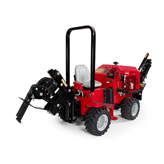
Toro Pro Sneak 365 Operator's Manual
Vibratory plow
Hide thumbs
Also See for Pro Sneak 365:
- Installation instructions (4 pages) ,
- Operator's manual (44 pages) ,
- Operator's manual (16 pages)

Related Manuals for Toro Pro Sneak 365


Summary of Contents for Toro Pro Sneak 365
- Page 1 Form No. 3429-934 Rev B Pro Sneak 365 Vibratory Plow Model No. 25403—Serial No. 404600000 and Up *3429-934* Register at www.Toro.com. Original Instructions (EN)
- Page 2 Section 4442 or 4443 to use or operate the engine on additional information, contact an Authorized Service any forest-covered, brush-covered, or grass-covered Dealer or Toro Customer Service and have the model land unless the engine is equipped with a spark and serial numbers of your product ready.
-
Page 3: Table Of Contents
Contents Cleaning the Directional Controls Linkage Assembly ............34 Hydraulic System Maintenance ......35 Safety ............... 4 Hydraulic System Safety........35 General Safety ........... 4 Servicing the Hydraulic System ......35 Safety and Instructional Decals ......5 ROPS Maintenance ..........38 Product Overview ............11 Checking and Servicing the ROPS .... -
Page 4: Safety
Safety Improperly using, modifying, or maintaining this machine can result in injury. To reduce the potential for injury, comply with these safety instructions and always pay attention to the safety-alert symbol DANGER which means Caution, Warning, or Danger—personal There may be buried utility lines in the work safety instruction. -
Page 5: Safety And Instructional Decals
Safety and Instructional Decals Safety decals and instructions are easily visible to the operator and are located near any area of potential danger. Replace any decal that is damaged or missing. decal106-5976 106-5976 1. Engine coolant under 3. Warning—do not touch the pressure hot surface. - Page 6 decal125-8483 125–8483 1. Hydraulic fluid; read the Operator’s Manual. g036698 Figure 4 decal125-6672 125–6672 1. 125-4963 3. 125-8483 2. 130-4291 4. 125-6672 1. Crushing hazard—stay away from articulated joints. decal125-4963 125-4963 1. Warning—do not touch hot surfaces. decal130-4291 g036696 130-4291 Figure 5 1.
- Page 7 decal130-7361 130-7361 1. Raise the plow 3. Lower the trencher 2. Lower the plower 4. Raise the trencher decal130-7360 130-7360 1. Engine—off 3. Engine—start 2. Engine—run/warming decal125-6680 125–6680 decal130-4341 1. Read the Operator’s 4. Fast 130-4341 Manual. 2. Turn left 5.
- Page 8 decal133-8062 133-8062 decal130-4340 130-4340 1. Fast 3. Slow 2. Engine speed decal130-4343 130-4343 1. Warning—read the 5. Warning—keep Operator's Manual. bystanders away. 2. Warning—do not operate 6. Warning—keep away the machine unless you from moving parts; keep have received instruction. all guards and shields in place.
- Page 9 decal125-6135 125–6135 g036695 Figure 7 1. 125-8487 (behind the 3. 125-8491 (behind the step) rubber guard) 2. 125-6135 (under the seat) decal125-8491 125–8491 1. Crushing hazard, warning—keep away from articulated joints; replace missing safety shields. decal125-8487 125–8487 1. Crushing hazard, tire—read the Operator’s Manual; the extension step must be attached when the tires are in wide or doubled configuration.
- Page 10 decal127-1822 127-1822 1. The engine cannot start 4. No vibration with the plow active. g036697 Figure 8 2. High vibration 5. The engine can start with the plow inactive. 1. 127-1822 4. 125-6684 3. Low vibration 2. 125-4967 5. 125-6694 3.
-
Page 11: Product Overview
Controls Product Overview Become familiar with all of the controls before you start the engine and operate the machine. Throttle The throttle controls the engine speed. Push the knob to increase the engine speed. Pull the knob to decrease the engine speed. Parking-Brake Lever To set the parking brake, pull the lever up and push it forward. - Page 12 Creep-Control Lever Over time, ash accumulates in the DPF and a background regeneration is not sufficient to unclog the The creep-control lever controls the direction and filter. When this occurs, the regeneration request and speed of the machine while the attachments are check engine lights illuminate on the control panel.
-
Page 13: Specifications
This light illuminates when all control levers are in the your Authorized Service Dealer or authorized Toro position. EUTRAL distributor or go to www.Toro.com for a list of all approved attachments and accessories. Air-Filter Light To ensure optimum performance, use only This light illuminates if the air filter is in need of genuine Toro replacement parts and accessories. -
Page 14: Before Operation
Fuel Safety Operation • Use extra care when handling fuel. It is flammable and its vapors are explosive. Note: Determine the left and right sides of the machine from the normal operating position. • Extinguish all cigarettes, cigars, pipes, and other sources of ignition. -
Page 15: Checking The Interlock System
Biodiesel Ready Checking the Interlock System This machine can also use a biodiesel blended fuel of up to B20 (20% biodiesel, 80% petrodiesel). The petrodiesel portion should be low or ultra low sulfur. Before using the machine, make the following interlock Observe the following precautions: system checks. -
Page 16: During Operation
• Use only Toro-approved attachments and attentive to the surroundings. accessories. Attachments can change the stability •... -
Page 17: Rotating The Wheels
– Embankments – Bodies of water The machine could suddenly roll over if a tire goes over the edge or the edge caves in. Maintain a safe distance between the machine and any hazard. • Do not remove or add attachments on a slope. •... -
Page 18: Operating The Vibratory Plow
Shutting Off the Engine Release the parking brake. Move the throttle lever to the S position. Note: Do not start the plow vibration until the blade tip has entered the ground. Lower any attachments to the ground. Move the vibratory-plow lever to start the plow Set all controls to the N position. -
Page 19: After Operation
g025774 Figure 17 1. Snap-ring pin 2. Pin g021986 Figure 18 Pull the 2 pins out of the blade. 1. Nut 4. Washer 2. Washer 5. Bolt Note: The plow blades are heavy. Make sure 3. Skid shoes that 1 person is holding the blade while the other person is removing the pins. -
Page 20: Transporting The Machine
Transporting the Machine Loading the Machine Important: Ensure that the trailer and ramp can support both your weight plus the weight of the machine with any attachments. Start the engine. Move the attachments to transport position. Secure the trailer hitch to your vehicle and put a block at the front and rear of the trailer wheels. -
Page 21: Maintenance
Determine the left and right sides of the machine from the normal operating position. Download a free copy of the electrical or hydraulic schematic by visiting www.Toro.com and searching for your machine from the Manuals link on the home page. -
Page 22: Pre-Maintenance Procedures
Maintenance Service Maintenance Procedure Interval • Check the battery electrolyte level (replacement battery only). • Check the axle oil levels. • Check the cooling system hoses. Every 100 hours • Check the hydraulic lines for leaks, loose fittings, kinked lines, loose mounting supports, wear, weather, and chemical deterioration. -
Page 23: Lubrication
Lubrication Greasing the Machine Service Interval: Before each use or daily (Grease immediately after every washing). Grease Type: General-purpose grease. Clean the grease fittings with a rag. Connect a grease gun to each fitting (Figure Figure 23, and Figure g026667 Figure 24 Underside view g021987... -
Page 24: Engine Maintenance
Engine Maintenance Engine Safety • Shut off the engine before checking the oil or adding oil to the crankcase. g026666 Figure 25 • Do not change the engine governor setting or overspeed the engine. 1. Latch 5. Air filter 2. Dust cap 6. -
Page 25: Servicing The Engine Oil
Servicing the Engine Oil Park the machine on a level surface, lower any attachments, shut off the engine, and remove Service Interval: After the first 50 hours—Change the key. the engine oil and filter. Unlock the engine cover latches and open the Before each use or daily—Check the engine oil engine cover. - Page 26 Remove the filler cap and the drain plug (Figure 28). g020436 Figure 29 1. Oil filter g025666 Figure 28 1. Oil-drain plug Apply a thin layer of clean oil to the gasket seal of the new oil filter. Apply a thin coat of the clean oil of the proper When the oil has drained completely, install the type through the center hole of the filter.
-
Page 27: Servicing The Diesel Particulate Filter (Dpf)
Servicing the Diesel Fuel System Particulate Filter (DPF) Maintenance Service Interval: Every 3,000 hours DANGER Over time, ash accumulates in the DPF and a Under certain conditions, diesel fuel and fuel background regeneration is not sufficient to unclog the vapors are highly flammable and explosive. A filter. -
Page 28: Replacing The Fuel Filter Canister
Replacing the Fuel Filter Electrical System Canister Maintenance Service Interval: Every 500 hours—Replace the fuel filter/water separator. Electrical System Safety Clean the filter head and the outside of the fuel • Disconnect the battery before repairing the filter. machine. Disconnect the negative terminal first Turn the filter counterclockwise and remove the and the positive last. -
Page 29: Drive System Maintenance
Charging the Battery Drive System Maintenance WARNING Charging the battery produces gasses that can explode. Servicing the Tires Never smoke near the battery and keep sparks and flames away from battery. Checking the Tires and Lug Nuts Important: Always keep the battery fully charged Service Interval: Before each use or daily—Check (1.265 specific gravity). -
Page 30: Servicing The Transmission And Axles
GL5 Front axle oil capacity: approximately 2.4 L (2.5 US Rear axle oil capacity: approximately 2.4 L (2.5 US Toro Premium Gear Oil is available from an Authorized Service Dealer. See the parts catalog for part numbers. Checking the Transmission Oil... -
Page 31: Cooling System Maintenance
Cooling System Note: The oil level should be even with the bottom of the fill plug hole. Maintenance Add oil to raise the oil level up to the bottom of the fill plug hole. Install the fill plug. Cooling System Safety Repeat for the other differential. - Page 32 Check the coolant level in the radiator. DANGER Note: The radiator should be filled to the top of Rotating shaft and fan can cause personal the filler neck and the expansion tank filled to injury. the Full mark (Figure 36). •...
-
Page 33: Belt Maintenance
Belt Maintenance Replacing the Drive Belt Service Interval: Every 4,000 hours—Replace the alternator drive belt. Checking the Alternator Loosen the pivot bolts, the adjusting bolt, and Drive Belt Tension move the alternator toward the engine to loosen the belt tension. Service Interval: Every 1,000 hours Remove the drive belt and install the new drive Push the drive belt with your thumb in the area... -
Page 34: Controls System Maintenance
Controls System Maintenance The factory adjusts the controls before shipping the machine However, after many hours of use, you may need to adjust the controls. Important: To adjust the controls properly, complete each procedure in the order listed. Checking the Parking Brake Move the parking brake lever to the On position. -
Page 35: Hydraulic System Maintenance
(Available in 5-gallon pails or 55-gallon drums. See Parts Catalog or an Authorized Service Dealer for part numbers.) Alternate fluids: If the Toro fluid is not available, other fluids may be used provided they meet all the following material properties and industry specifications. We do not recommend the use of synthetic fluid. - Page 36 Clean up any spilled fluid. Install the cap on the filler neck. Start the engine and let it run for about 2 minutes Close the hood. to purge any air from the system. Shut off the engine and check for leaks. Changing the Hydraulic Fluid Service Interval: After the first 250 hours Checking the Hydraulic-Fluid...
- Page 37 Install the hose to the tank and secure the clamps. Install the hydraulic tank assembly. Fill the hydraulic tank with approximately 25.8 L (6.8 US gallons) of Toro premium all season hydraulic fluid ISO VG 46. Dispose of the used oil at a certified recycling center.
-
Page 38: Rops Maintenance
ROPS Maintenance Start the engine and let it run for a few minutes. Shut off the engine. Check the hydraulic fluid level and top it off if Checking and Servicing the necessary; refer to Checking the Hydraulic-Fluid ROPS Level (page 36). -
Page 39: Cleaning
Cleaning Removing Debris from the Machine Service Interval: Before each use or daily Important: Operating the engine with blocked screens and/or cooling shrouds removed, will result in engine damage from overheating. Park the machine on a level surface, lower any attachments, and shut off the engine. -
Page 40: Storage
Storage Storage Safety • Shut off the engine, remove the key, wait for all moving parts to stop, and allow the machine to cool before storing it. • Do not store the machine or fuel near flames. Storage Lower any attachments, shut off the engine, and remove the key. -
Page 41: Troubleshooting
Troubleshooting Problem Possible Cause Corrective Action The starter does not crank. 1. The controls are not in the neutral 1. Move all of the controls to the Neutral position. position. 2. The electrical connections are 2. Check the electrical connections for corroded or loose. - Page 42 Problem Possible Cause Corrective Action The engine starts, but does not keep 1. The fuel tank vent is restricted. 1. Loosen the cap. If the engine runs with running. the cap loosened, replace the cap. 2. There is dirt or water is in the fuel 2.
- Page 43 Problem Possible Cause Corrective Action The engine overheats. 1. More coolant is needed. 1. Check and add coolant. 2. There is restricted air flow to the 2. Inspect and clean the side panel radiator. screens with every use. 3. The crankcase oil level is incorrect. 3.
- Page 44 Problem Possible Cause Corrective Action The engine loses power. 1. The engine load is excessive. 1. Reduce the load; use lower ground speed. 2. The crankcase oil level is incorrect. 2. Fill or drain to the full mark. 3. The air cleaner filters are dirty. 3.
- Page 45 Notes:...
- Page 46 Notes:...
- Page 47 While the exposure from Toro products may be negligible or well within the “no significant risk” range, out of an abundance of caution, Toro has elected to provide the Prop 65 warnings. Moreover, if Toro does not provide these warnings, it could be sued by the State of California or by private parties seeking to enforce Prop 65 and subject to substantial penalties.