Siemens SINAMICS S120 Equipment Manual
Booksize power units
Hide thumbs
Also See for SINAMICS S120:
- Function manual (1094 pages) ,
- Diagnostic manual (947 pages) ,
- Manual (848 pages)
Table of Contents
Advertisement
Quick Links
Advertisement
Table of Contents

Related Manuals for Siemens SINAMICS S120


Summary of Contents for Siemens SINAMICS S120
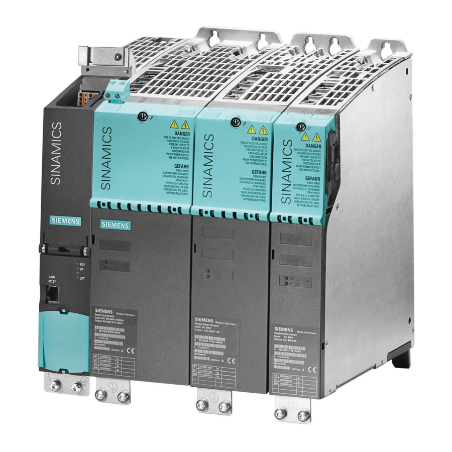
- Page 1 SINAMICS S120 Booksize Power Units sinamics...
-
Page 3: Line Modules Booksize
Foreword System Overview Line Connection Booksize SINAMICS Line Modules Booksize S120 SINAMICS S120 Booksize Power Motor Modules Booksize Units Booksize DC Link Components Equipment Manual Motor-Side Power Components Accessories Cabinet Design and EMC Booksize Service and Support Booksize Appendix A... - Page 4 Trademarks All names identified by ® are registered trademarks of the Siemens AG. The remaining trademarks in this publication may be trademarks whose use by third parties for their own purposes could violate the rights of the owner.
-
Page 5: Foreword
Orientation SINAMICS S Sales Documentation Planning/configuration SIZER Configuration Tool Decision/ordering SINAMICS S Catalogs SINAMICS S120 Equipment Manual for Control Units and Installation/assembly • Supplementary System Components SINAMICS S120 Equipment Manual Power Modules Booksize • SINAMICS S120 Equipment Manual Power Modules Chassis •... -
Page 6: Components
Foreword Usage phase Tools SINAMICS S120 Commissioning Manual Usage/operation • SINAMICS S List Manual • SINAMICS S150 Operating Instructions • SINAMICS S120 Commissioning Manual Maintenance/servicing • SINAMICS S List Manual • SINAMICS S150 Operating Instructions • Target group This Manual addresses planners, installation technicians, design engineers. - Page 7 If you have any questions (suggestions, corrections) regarding this documentation, please fax or e-mail us at: +49 9131 98 63315 E-mail E-mail to: docu.motioncontrol@siemens.com A fax form is available in the appendix of this document. Internet address for SINAMICS http://www.siemens.com/sinamics.
-
Page 8: Booksize
● in the Internet: http://support.automation.siemens.com under the Product/Order No. 15257461 ● with the responsible branch office of the A&D MC Business Division of Siemens AG. The EC Declaration of Conformity for the Low Voltage Directive can be found/obtained ● on the Internet http://support.automation.siemens.com... - Page 9 Foreword ESD information CAUTION Electrostatic sensitive devices (ESDs) are individual components, integrated circuits, or boards that may be damaged by either electrostatic fields or electrostatic discharge. Regulations for handling ESD components: When handling components, make sure that personnel, workplaces, and packaging are well earthed.
- Page 10 Foreword DANGER Correct and safe operation of SINAMICS S units assumes correct transportation in the transportation packaging, correct long-term storage in the transport packaging, setup and installation, as well as careful operation and maintenance. The details in the catalogs and proposals also apply to the design of special equipment versions.
- Page 11 Foreword Explanation of symbols The symbols are in accordance with IEC 617-2. Table 2 Symbols Symbol Description Protective earth (PE) Ground (e.g. M 24 V) Functional ground (e.g. shield) Equipotential bonding Booksize Power Units Equipment Manual, (GH2), 07/2007, 6SL3097-2AC00-0BP5...
- Page 12 Foreword Residual risks of power drive systems When carrying out a risk assessment of the machine in accordance with the EU Machinery Directive, the machine manufacturer must consider the following residual risks associated with the control and drive components of a power drive system (PDS). 1.
-
Page 13: Table Of Contents
Table of contents Foreword ..............................5 System Overview............................. 21 Field of application ........................21 Versions ............................22 Platform concept and Totally Integrated Automation..............23 Introduction ..........................24 SINAMICS S120 components......................27 Power sections..........................29 System data ..........................30 Standards.............................32 Line Connection Booksize ........................35 Introduction ..........................35 Overview: Line filters........................37 Combining line reactors and line filters..................39... - Page 14 Table of contents Basic Line Filter for Basic Line Modules ..................62 2.7.1 Description ..........................62 2.7.2 Safety information ........................62 2.7.3 Interface description........................64 2.7.3.1 Overview ............................. 64 2.7.3.2 Line/power connection ........................ 65 2.7.4 Dimension drawing........................65 2.7.5 Technical data..........................66 Basic Line Filter for Smart Line Modules ..................
- Page 15 Table of contents 2.13 Line connection variants ......................104 2.13.1 Ways of connecting the line supply ...................104 2.13.2 Operating line connection components on the line supply ............105 2.13.3 Operating line connection components via a matching transformer..........106 2.13.3.1 Safety information ........................106 2.13.3.2 Line supply connection conditions for Line Modules ..............106 2.13.3.3 Operation of the line connection components via an autotransformer ........113 2.13.3.4 Assignment of autotransformers to Active Line Modules ............115 2.13.3.5 Assignment of autotransformers to Smart Line Modules............117...
- Page 16 Table of contents 3.4.3.1 Overview ........................... 189 3.4.3.2 Connection example ......................... 192 3.4.3.3 X1 line connection........................194 3.4.3.4 X24 24 V terminal adapter ......................195 3.4.3.5 X200-X202 DRIVE-CLiQ interfaces ..................196 3.4.3.6 X2 braking resistor connection....................196 3.4.3.7 X21 EP terminals ........................197 3.4.3.8 Meaning of the LEDs on the Basic Line Module...............
- Page 17 Table of contents 3.7.4 Dimension drawing ........................261 3.7.5 Installation ..........................262 3.7.6 Electrical connection ........................268 3.7.7 Technical data..........................269 Motor Modules Booksize ........................273 Introduction ..........................273 Motor Modules with internal air cooling ..................275 4.2.1 Description ..........................275 4.2.2 Safety information ........................275 4.2.3 Interface description........................278 4.2.3.1 Overview ............................278 4.2.3.2...
- Page 18 Table of contents 5.2.3 Interface description........................344 5.2.3.1 Overview ........................... 344 5.2.4 Dimension drawing........................345 5.2.5 Installation ..........................346 5.2.6 Technical data........................... 347 Control Supply Module......................348 5.3.1 Description ..........................348 5.3.2 Safety information ........................348 5.3.3 Interface description........................350 5.3.3.1 Overview ...........................
- Page 19 Table of contents 7.3.4 Dimension drawing ........................406 7.3.5 Mounting ............................407 7.3.6 Electrical connection ........................409 Reinforced DC-link busbars .......................410 7.4.1 Description ..........................410 7.4.2 Safety information ........................411 7.4.3 Dimension drawings........................412 7.4.4 Removing the DC link busbars ....................414 7.4.5 Mounting the reinforced DC link busbars...................414 DRIVE-CLiQ cabinet gland ......................415 7.5.1 Description ..........................415...
- Page 20 Table of contents Connection systems........................455 8.6.1 Spring-loaded terminals/screw terminals .................. 455 8.6.2 Connectable cable cross-sections .................... 456 8.6.3 Motor connector ........................459 8.6.4 Power connector (X1/X2) ......................461 8.6.5 24 V terminal adapter........................ 464 Cooling ............................465 8.7.1 General............................465 8.7.2 Information about ventilation .....................
-
Page 21: System Overview
System Overview Field of application SINAMICS is the new range of drives from Siemens designed for mechanical and plant engineering applications. SINAMICS offers solutions for all drive tasks: ● Simple pump and fan applications in the process industry. ● Complex individual drives in centrifuges, presses, extruders, elevators, as well as conveyor and transport systems. -
Page 22: Versions
System Overview 1.2 Versions Versions SINAMICS offers different versions designed to meet a range of requirements: ● SINAMICS G is designed for standard applications with induction motors. These applications have less stringent requirements regarding the dynamics and accuracy of the motor speed. ●... -
Page 23: Platform Concept And Totally Integrated Automation
The different SINAMICS versions can be easily combined with each other. SINAMICS is part of the Siemens "Totally Integrated Automation" concept. Integrated SINAMICS systems covering configuration, data storage, and communication at automation level, ensure low-maintenance solutions with SIMATIC, SIMOTION, and SINUMERIK. -
Page 24: Introduction
System Overview 1.4 Introduction Introduction Figure 1-3 SINAMICS S120 system overview Booksize Power Units Equipment Manual, (GH2), 07/2007, 6SL3097-2AC00-0BP5... - Page 25 Inter-axis connections can be established within a component and easily configured in the STARTER commissioning tool using a mouse. Simple technological tasks can be carried out by the SINAMICS S120 Control Unit itself. For complex numerical or motion-control tasks, high-performance SINUMERIK or SIMOTION D modules are used instead.
- Page 26 1.4 Introduction Electronic type plates in all components All SINAMICS S120 components have an electronic type plate. This electronic type plate contains all the relevant technical data about that particular component. In the motors, for example, this data includes the parameters of the electric equivalent circuit diagram and characteristic values for the built-in motor encoder.
-
Page 27: Sinamics S120 Components
System Overview 1.5 SINAMICS S120 components SINAMICS S120 components This overview features the SINAMICS S120 components that are primarily used for multi- axis drive tasks. Figure 1-5 SINAMICS S120 component overview Booksize Power Units Equipment Manual, (GH2), 07/2007, 6SL3097-2AC00-0BP5... - Page 28 ● Supplementary system components that enhance functionality and offer different interfaces for encoders and process signals. SINAMICS S120 components were developed for installation in cabinets. They have the following features and characteristics: ● Easy to handle, simple installation and wiring ●...
-
Page 29: Power Sections
System Overview 1.6 Power sections Power sections Line Modules Convert the three-phase supply into a DC voltage for the DC link. ● Smart Line Modules The Smart Line Modules generate a non-stabilized DC link voltage and are capable of regenerative feedback. ●... -
Page 30: System Data
1.7 System data System data Technical data Unless explicitly specified otherwise, the following technical data are valid for components of the SINAMICS S120 booksize drive system. Electrical data Line connection voltage 380 V to 480 V 3 AC ±10 % (-15 % <... - Page 31 System Overview 1.7 System data Environmental conditions Degree of protection IP20 or IPXXB to EN 60529, open type to UL508 Protection class for network current circuits I (with protective conductor connection) and Protection class for electronic circuits III (protective extra low voltage DVC A / PELV) acc. to EN 61 800-5-1 Permissible coolant temperature (air) and installation 0 °C to +40 °C and an installation altitude of up to 1000 m...
-
Page 32: Standards
System Overview 1.8 Standards Standards Table 1-1 Essentially the application-relevant standards Standards Title EN ISO 12100-1 Safety of Machinery; General Design Guidelines; Part 1: Basic terminology, methodology EN ISO 12100-2 Safety of Machinery; General Design Guidelines; Part 2: Technical Principles and Specifications EN 563 Safety of machinery;... - Page 33 System Overview 1.8 Standards Standards Title EN 61800-5-X Adjustable-speed electrical power drive systems; Part 5: Safety requirements; Main section 1: Electrical, thermal and energy requirements Main section 2: Functional safety requirements VDE 0100 Teil X Erection of power installations with nominal voltages up to 1000 V; (IEC 60364-X-X) Part 200: Definitions Part 410: Protection for safety, protection against electric shock...
- Page 34 System Overview 1.8 Standards Booksize Power Units Equipment Manual, (GH2), 07/2007, 6SL3097-2AC00-0BP5...
-
Page 35: Line Connection Booksize
● Line reactor variants: – Line reactors for Active Line Modules – Line reactors for Smart Line Modules – Line reactor for Basic Line Modules Figure 2-1 Overview: Line connection SINAMICS S120 Booksize Power Units Equipment Manual, (GH2), 07/2007, 6SL3097-2AC00-0BP5... - Page 36 Overview: line connection with Active Interface Module CAUTION Using line filters not approved by SIEMENS for SINAMICS can lead to damage/ interference to the Line Modules and line-side harmonics that can interfere with or damage other loads operated by the network.
-
Page 37: Overview: Line Filters
2.2 Overview: Line filters Overview: Line filters A separate line filter (see catalog) must be used for the SINAMICS S120 drive line-up. An additional line filter must be used to suppress interference in other loads. To prevent mutual interference, this line filter must not be equipped with line-side capacitors with respect to ground. - Page 38 Line Connection Booksize 2.2 Overview: Line filters Basic Line Filter for Smart Line Modules Basic Line Filters for Smart Line Modules are specified for total cable lengths of up to 150 m (shielded) of category C2 to EN 61800-3. Basic Line Filters 16 kW and 36 kW for Smart Line Modules are specified for total cable lengths of up to 350 m (shielded) of category C2 to EN 61800-3.
-
Page 39: Combining Line Reactors And Line Filters
Line Connection Booksize 2.3 Combining line reactors and line filters Combining line reactors and line filters Figure 2-3 Combining line reactors and line filters Booksize Power Units Equipment Manual, (GH2), 07/2007, 6SL3097-2AC00-0BP5... -
Page 40: Basic Line Filter For Active Line Modules With Line Reactor
Line Connection Booksize 2.4 Basic Line Filter for Active Line Modules with line reactor Basic Line Filter for Active Line Modules with line reactor 2.4.1 Description The Basic Line Filters for Active Line Modules are designed for limiting the cable-borne interference in accordance with the specifications of the EMC legislation. - Page 41 Line Connection Booksize 2.4 Basic Line Filter for Active Line Modules with line reactor DANGER The line filters listed conduct a high leakage current via the PE conductor. A permanent PE connection for the line filter or control cabinet is required due to the high leakage current of the line filters.
-
Page 42: Interface Description
Line Connection Booksize 2.4 Basic Line Filter for Active Line Modules with line reactor 2.4.3 Interface description 2.4.3.1 Overview Figure 2-4 Basic Line Filter for Active Line Modules (example: 36 kW) WARNING The line/load connection must not be interchanged. Booksize Power Units Equipment Manual, (GH2), 07/2007, 6SL3097-2AC00-0BP5... -
Page 43: Line Supply/Load Connection
Line Connection Booksize 2.4 Basic Line Filter for Active Line Modules with line reactor 2.4.3.2 Line supply/load connection Table 2-2 Type of connection Terminals Designations Line supply connection (line supply) L1, L2, L3, PE Load connection (load) L1´, L2´, L3´, PE Basic Line Filter for Active Line Modules 16 kW Screw terminal: 10 mm... -
Page 44: Dimension Drawing
Line Connection Booksize 2.4 Basic Line Filter for Active Line Modules with line reactor 2.4.4 Dimension drawing Figure 2-5 Dimension drawing: Basic Line Filter for Active Line Modules (16 kW to 55 kW) Table 2-3 Dimensions: Basic Line Filter for Active Line Modules Basic Line Order number W [mm]... -
Page 45: Technical Data
Line Connection Booksize 2.4 Basic Line Filter for Active Line Modules with line reactor 2.4.5 Technical data Table 2-4 Technical data of Basic Line Filter for Active Line Modules with line reactor 6SL3000 0BE21-6DAx 0BE23-6DAx 0BE25-5DAx unit Rated power Connection voltage: Supply voltage 380 V 3 AC -10 % (-15 % <... -
Page 46: Basic Line Filter For Active Line Modules With Active Interface Module
Line Connection Booksize 2.5 Basic Line Filter for Active Line Modules with Active Interface Module Basic Line Filter for Active Line Modules with Active Interface Module 2.5.1 Description Basic Line Filters are mainly effective in the frequency range from 150 kHz to 30 MHz; this is the range relevant to ensure compliance with the appropriate standard. - Page 47 Line Connection Booksize 2.5 Basic Line Filter for Active Line Modules with Active Interface Module NOTICE The associated Line Module must only be connected to the SINAMICS line filter via the associated line reactor. Additional loads must be connected upstream of the SINAMICS line filter (if required, via a separate line filter).
-
Page 48: Interface Description
Line Connection Booksize 2.5 Basic Line Filter for Active Line Modules with Active Interface Module 2.5.3 Interface description 2.5.3.1 Overview Figure 2-6 Interface description: Basic Line Filter 55 kW Booksize Power Units Equipment Manual, (GH2), 07/2007, 6SL3097-2AC00-0BP5... - Page 49 Line Connection Booksize 2.5 Basic Line Filter for Active Line Modules with Active Interface Module Figure 2-7 Interface description: 80 kW and 120 kW Basic Line Filter NOTICE The line/load connection must not be interchanged. Booksize Power Units Equipment Manual, (GH2), 07/2007, 6SL3097-2AC00-0BP5...
-
Page 50: Line/Power Connection
Line Connection Booksize 2.5 Basic Line Filter for Active Line Modules with Active Interface Module 2.5.3.2 Line/power connection Table 2-5 Connection type Terminals Designations Line supply connection (line supply) L1, L2, L3, PE Load connection (load) L1´, L2´, L3´, PE Basic Line Filter for Active Line Module with Active Interface Module 55 kW Screw terminal: 95 mm... -
Page 51: Technical Data
Line Connection Booksize 2.5 Basic Line Filter for Active Line Modules with Active Interface Module Figure 2-9 Dimension drawing: 80 kW and 120 kW Basic Line Filter Table 2-7 Dimensions: Basic Line Filter for Active Line Modules Basic Line Order number W [mm] w [mm] a [mm]... -
Page 52: Wideband Line Filter For Active Line Modules
Line Connection Booksize 2.6 Wideband Line Filter for Active Line Modules Wideband Line Filter for Active Line Modules 2.6.1 Description The damping characteristics of Wideband Line Filters for Active Line Modules not only conform with the requirements of EMC standards for the frequency range of 150 kHz to 30 MHz but also include low frequencies as of 2 kHz. - Page 53 Line Connection Booksize 2.6 Wideband Line Filter for Active Line Modules DANGER The line filters listed conduct a high leakage current via the protective ground conductor. A permanent PE connection for the line filter or control cabinet is required due to the high leakage current of the line filters.
-
Page 54: Interface Description
Line Connection Booksize 2.6 Wideband Line Filter for Active Line Modules 2.6.3 Interface description Figure 2-10 Wideband Line Filter for Active Line Module (example: 16 kW) NOTICE The line/load connection must not be interchanged. Booksize Power Units Equipment Manual, (GH2), 07/2007, 6SL3097-2AC00-0BP5... -
Page 55: Line/Power Connection
Line Connection Booksize 2.6 Wideband Line Filter for Active Line Modules 2.6.3.1 Line/power connection Table 2-9 Type of connection Terminals Designations Line supply connection (line supply) L1, L2, L3, PE Load connection (load) U, V, W Wideband Line Filter for Active Line Modules 16 kW Screw terminal: 10 mm 3-pin/1.5 -1.8 Nm (see Screw Terminals chapter) -
Page 56: Dimension Drawings
Line Connection Booksize 2.6 Wideband Line Filter for Active Line Modules 2.6.4 Dimension drawings Figure 2-11 Dimension drawing: 16 kW Wideband Line Filter for Active Line Modules Booksize Power Units Equipment Manual, (GH2), 07/2007, 6SL3097-2AC00-0BP5... - Page 57 Line Connection Booksize 2.6 Wideband Line Filter for Active Line Modules Figure 2-12 Dimension drawing: 36 kW Wideband Line Filter for Active Line Modules Booksize Power Units Equipment Manual, (GH2), 07/2007, 6SL3097-2AC00-0BP5...
- Page 58 Line Connection Booksize 2.6 Wideband Line Filter for Active Line Modules Figure 2-13 Dimension drawing: 55 kW Wideband Line Filter for Active Line Modules Booksize Power Units Equipment Manual, (GH2), 07/2007, 6SL3097-2AC00-0BP5...
- Page 59 Line Connection Booksize 2.6 Wideband Line Filter for Active Line Modules Figure 2-14 Dimension drawing: 80 kW Wideband Line Filter for Active Line Modules Booksize Power Units Equipment Manual, (GH2), 07/2007, 6SL3097-2AC00-0BP5...
- Page 60 Line Connection Booksize 2.6 Wideband Line Filter for Active Line Modules Figure 2-15 Dimension drawing: 120 kW Wideband Line Filter for Active Line Modules Table 2-10 Wideband Line Filter For Active Line Modules Order no. 16 kW 6SL3000-0BE-21-6AAx 36 kW 6SL3000-0BE-23-6AAx 55 kW 6SL3000-0BE-25-5AAx...
-
Page 61: Technical Data
Line Connection Booksize 2.6 Wideband Line Filter for Active Line Modules 2.6.5 Technical data Table 2-11 Technical data: Wideband Line Filter for Active Line Modules 6SL3000 0BE21- 0BE23- 0BE25- 0BE28- 0BE31- unit 6AAx 6AAx 5AAx 0AAx 2AAx Rated power Connection voltages: Supply voltage 380 V 3 AC -10 % (-15 % <... -
Page 62: Basic Line Filter For Basic Line Modules
Line Connection Booksize 2.7 Basic Line Filter for Basic Line Modules Basic Line Filter for Basic Line Modules 2.7.1 Description The Basic Line Filters for Basic Line Modules are designed for limiting the cable-borne interference in the frequency range in accordance with the specifications of the EMC legislation. - Page 63 Line Connection Booksize 2.7 Basic Line Filter for Basic Line Modules DANGER The line filters listed conduct a high leakage current via the protective ground conductor. A permanent PE connection for the line filter or control cabinet is required due to the high leakage current of the line filters.
-
Page 64: Interface Description
Line Connection Booksize 2.7 Basic Line Filter for Basic Line Modules 2.7.3 Interface description 2.7.3.1 Overview Figure 2-16 Line filters for Basic Line Modules (example: 40 kW) NOTICE The line/load connection must not be interchanged. Booksize Power Units Equipment Manual, (GH2), 07/2007, 6SL3097-2AC00-0BP5... -
Page 65: Line/Power Connection
Line Connection Booksize 2.7 Basic Line Filter for Basic Line Modules 2.7.3.2 Line/power connection Table 2-12 Connection type Terminals Designations Line supply connection (line supply) L1, L2, L3, PE Load connection (load) L1´, L2´, L3´, PE Basic Line Filter for Basic Line Modules 20 kW Screw terminal: 10 mm 3-pin / 1.5 - 1.8 Nm (see Screw Terminals chapter) -
Page 66: Technical Data
Line Connection Booksize 2.7 Basic Line Filter for Basic Line Modules Figure 2-18 Dimension drawing of Basic Line Filter for 100 kW Basic Line Modules Table 2-14 Dimensions of Basic Line Filter for Basic Line Modules Basic Line Order number B [mm] b [mm] a [mm]... -
Page 67: Basic Line Filter For Smart Line Modules
Line Connection Booksize 2.8 Basic Line Filter for Smart Line Modules Basic Line Filter for Smart Line Modules 2.8.1 Description In conjunction with the associated line reactors, the Basic Line Filters for Smart Line Modules limit the cable-borne interference to a level in compliance with EN61800-3 category In conjunction with the line filters and the associated line reactors, drive line-ups with Smart Line Modules fulfill the requirements of category C2 to EN 61800-3. - Page 68 Line Connection Booksize 2.8 Basic Line Filter for Smart Line Modules DANGER Risk of electric shock. Dangerous voltages are still present for up to 5 minutes after the power supply has been switched off. Note If a high-voltage test is conducted with alternating voltage in the system, the line filters must be disconnected in order to obtain accurate measurements.
-
Page 69: Interface Description
Line Connection Booksize 2.8 Basic Line Filter for Smart Line Modules 2.8.3 Interface description 2.8.3.1 Overview Figure 2-19 Basic Line Filter for Smart Line Modules (example: 36 kW) NOTICE The line/load connection must not be interchanged. Booksize Power Units Equipment Manual, (GH2), 07/2007, 6SL3097-2AC00-0BP5... -
Page 70: Line/Power Connection
Line Connection Booksize 2.8 Basic Line Filter for Smart Line Modules Line voltage 415 V 3 AC to 480 V AC + 10 % ● Controlled DC link voltage required, or ● limitation of the DC link voltage required due to motor isolation 2.8.3.2 Line/power connection Table 2-16... -
Page 71: Dimension Drawings
Line Connection Booksize 2.8 Basic Line Filter for Smart Line Modules 2.8.4 Dimension drawings Figure 2-20 Dimension drawing: Basic Line Filter for Smart Line Modules (5 and 10 kW) Table 2-17 Basic Line Filter for Smart Line Modules Basic Line Filter for Smart Line Modules Order number 5 kW 6SL3000-0HE15-0AAx... -
Page 72: Technical Data
Line Connection Booksize 2.8 Basic Line Filter for Smart Line Modules Figure 2-21 Dimension drawing: Basic Line Filter for Smart Line Modules (16 kW and 36 kW) Table 2-18 Dimensions of Basic Line Filter for Smart Line Modules Basic Line Order number W [mm] b [mm]... -
Page 73: Active Interface Modules (Internal Cooling)
Line Connection Booksize 2.9 Active Interface Modules (internal cooling) Active Interface Modules (internal cooling) 2.9.1 Description Active Interface Modules are line-side interfaces for the Active Line Modules. They contain the following functional units: ● Line reactors ● Low-frequency/switching frequency filters ●... -
Page 74: Safety Information
Line Connection Booksize 2.9 Active Interface Modules (internal cooling) 2.9.2 Safety information CAUTION Active Interface Modules must only be operated if the option "Line filter available" has been set for the Active Line Module in the commissioning wizard, and if "AIM 400 V xxkW (6SL3100-0BE**-*AB*)"... -
Page 75: Interface Description
Line Connection Booksize 2.9 Active Interface Modules (internal cooling) 2.9.3 Interface description 2.9.3.1 Overview Figure 2-22 Interface description: Active Interface Module 55 kW Booksize Power Units Equipment Manual, (GH2), 07/2007, 6SL3097-2AC00-0BP5... - Page 76 Line Connection Booksize 2.9 Active Interface Modules (internal cooling) Figure 2-23 Interface description: Active Interface Module (80 kW and 120 kW) Booksize Power Units Equipment Manual, (GH2), 07/2007, 6SL3097-2AC00-0BP5...
-
Page 77: Connection Example
Line Connection Booksize 2.9 Active Interface Modules (internal cooling) 2.9.3.2 Connection example Figure 2-24 Connection example: Active Interface Module Booksize Power Units Equipment Manual, (GH2), 07/2007, 6SL3097-2AC00-0BP5... -
Page 78: Electronics Power Supply X124
Line Connection Booksize 2.9 Active Interface Modules (internal cooling) 2.9.3.3 Electronics power supply X124 Table 2-20 Terminal block X124 Terminal Function Technical specifications Electronics power supply Voltage: 24 V DC (20.4 V - 28.8 V) Current consumption: max. 1.6 A Electronics power supply Max. -
Page 79: X121 Alarm Contacts For Temperature Switch
Line Connection Booksize 2.9 Active Interface Modules (internal cooling) 2.9.3.5 X121 alarm contacts for temperature switch Table 2-22 Plug-in screw terminal X121 Terminal Designation Technical specifications +Temp Rated current at cosφ 1: 2.5 A (max. 5 A) Voltage: 12 - 250 V (12 - 100 V Temperature switch output -Temp... -
Page 80: Dimension Drawings
Line Connection Booksize 2.9 Active Interface Modules (internal cooling) 2.9.4 Dimension drawings Figure 2-25 Dimension drawing: Active Interface Module 55 kW Booksize Power Units Equipment Manual, (GH2), 07/2007, 6SL3097-2AC00-0BP5... - Page 81 Line Connection Booksize 2.9 Active Interface Modules (internal cooling) Figure 2-26 Dimension drawing: Active Interface Module (80 kW and 120 kW) Table 2-23 Active Interface Modules Active Interface Module 6SL3100-0BE25-5ABx 6SL3100-0BE28-0ABx 6SL3100-0BE31-2ABx 55 kW 80 kW 120 kW Table 2-24 Shield connecting plates for Active Interface Modules Shield connecting plate 6SL3163-1AH00-0AAx...
-
Page 82: Installation
Line Connection Booksize 2.9 Active Interface Modules (internal cooling) 2.9.5 Installation The Active Interface Modules are designed for installation in the control cabinet. The components are secured onto the control cabinet installation panel next to the line filter using four M6 screws (not hexagon-head screws). Figure 2-27 Mounting: Active Interface Module Table 2-25... - Page 83 Line Connection Booksize 2.9 Active Interface Modules (internal cooling) Operating an Active Interface Module from an insulated network (IT system) When a 55 kW, 80 kW and 120 kW Active Interface Module is operated from an insulated supply (IT system), the connection bracket for the interference-suppression capacitor must be removed.
- Page 84 Line Connection Booksize 2.9 Active Interface Modules (internal cooling) Replacing the fan in an Active Interface Module NOTICE When replacing the fan, you must observe the ESD regulations. NOTICE Parts must only be replaced by trained personnel (danger of damage to sensitive components due to static electricity)! DANGER Before replacing the fan, you must switch off the power supplies (24 V DC and 400 V AC).
- Page 85 Line Connection Booksize 2.9 Active Interface Modules (internal cooling) Table 2-26 Replacing the fan in an Active Interface Module, 55 kW Open the fan cover. Unscrew the combination screws Open the fan cover and remove the connector M5 / 3 Nm Unscrew the screws M3 / 1.8 Nm Remove the fan Booksize Power Units...
- Page 86 Line Connection Booksize 2.9 Active Interface Modules (internal cooling) Table 2-27 Replacing the fan in an Active Interface Module, 80 kW, 120 kW Open the fan cover. Unscrew the Open the fan cover. Remove the connector. combination screws M5 / 3 Nm Unscrew the screws M3 / 1.8 Nm Release the connection cables Remove the fan.
-
Page 87: Technical Data
Line Connection Booksize 2.9 Active Interface Modules (internal cooling) 2.9.6 Technical data Table 2-28 Technical data Active Interface Module 6SL3100- 0BE25-5ABx 0BE28-0ABx 0BE31-2ABx 55 kW 80 kW 120 kW rated Current requirements of the 24 V DC electronics power supply Mains voltage 380 V to 480 V 3 AC ±10 % Line frequency... -
Page 88: Line Reactors For Active Line Modules
Only the line reactors or Active Interface Modules described in this Manual should be used. The following can occur if line reactors are used that have not been approved for SINAMICS S120 by SIEMENS: - The Line Modules may become damaged/faulty. -
Page 89: Connection Description
Line Connection Booksize 2.10 Line reactors for Active Line Modules 2.10.3 Connection description Figure 2-28 Line reactor (example: 16 kW) 2.10.3.1 Line/power connection Table 2-29 Connection types for line reactors Terminals Designations Line supply connection 1U1, 1V1, 1W1, PE Load connection 1U2, 1V2, 1W2 Line reactors for Active Line Modules 16 kW... -
Page 90: Dimension Drawings
Line Connection Booksize 2.10 Line reactors for Active Line Modules 2.10.4 Dimension drawings Figure 2-29 Dimension drawing: Line reactor for Active Line Modules (up to 55 kW) Table 2-30 Dimensions of the line reactor for Active Line Modules Order number L [mm] W [mm] h [mm]... -
Page 91: Technical Data
Line Connection Booksize 2.10 Line reactors for Active Line Modules Figure 2-30 Dimension drawing: Line reactor for Active Line Modules (as of 80 kW) Table 2-31 Dimensions of the line reactor for Active Line Modules Order L [mm] W [mm] h1 [mm] h2 [mm] H [mm]... -
Page 92: Line Reactors For Smart Line Modules
Only the line reactors or Active Interface Modules described in this Manual should be used. The following can occur if line reactors are used that have not been approved for SINAMICS S120 by SIEMENS: - The Line Modules may become damaged/faulty. -
Page 93: Connection Description
Line Connection Booksize 2.11 Line reactors for Smart Line Modules 2.11.3 Connection description Figure 2-31 Line reactors for Smart Line Modules (example: 36 kW) 2.11.3.1 Line/power connection Table 2-33 Connection types for line reactors Terminals Designations Line supply connection 1U1, 1V1, 1W1, PE Load connection 1U2, 1V2, 1W2 Line reactors for Smart Line Modules... -
Page 94: Dimension Drawings
Line Connection Booksize 2.11 Line reactors for Smart Line Modules 2.11.4 Dimension drawings Figure 2-32 Dimension drawing: Line reactor for Smart Line Modules (5 and 10 KW) Table 2-34 Dimensions of the line filter for Smart Line Modules Order number W [mm] b [mm] H [mm]... - Page 95 Line Connection Booksize 2.11 Line reactors for Smart Line Modules Figure 2-33 Dimension drawing of line reactor for the Smart Line Module 16 kW Booksize Power Units Equipment Manual, (GH2), 07/2007, 6SL3097-2AC00-0BP5...
- Page 96 Line Connection Booksize 2.11 Line reactors for Smart Line Modules Figure 2-34 Dimension drawing of the line reactor for the Smart Line Module 36 kW Table 2-35 Line reactor for the Smart Line Modules 16 kW and 36 kW Order No. 16 kW 6SL3000-0CE-21-6AAx 36 KW...
-
Page 97: Technical Data
Line Connection Booksize 2.11 Line reactors for Smart Line Modules 2.11.5 Technical data Table 2-36 Technical data of line reactors for the Smart Line Module 6SL3000 0CE15-0AAx 0CE21-0AAx 0CE22-0AAx 0CE24-0AAx unit Power Rated current Power loss Weight 1 For an overview, see the power loss tables in chapter Cabinet Design Booksize Power Units Equipment Manual, (GH2), 07/2007, 6SL3097-2AC00-0BP5... -
Page 98: Line Reactors For Basic Line Modules
Only the line reactors described in this Manual must be used. The following can occur if line reactors are used that have not been approved for SINAMICS S120 by SIEMENS: - The Line Modules may become damaged/faulty. - Line reactions can occur that can damage or interfere with other loads powered from the same network. -
Page 99: Connection Description
Line Connection Booksize 2.12 Line reactors for Basic Line Modules 2.12.3 Connection description 2.12.3.1 Overview Figure 2-35 Line reactor for Basic Line Module (20 kW) Figure 2-36 Line reactor for Basic Line Module (40 kW) Booksize Power Units Equipment Manual, (GH2), 07/2007, 6SL3097-2AC00-0BP5... -
Page 100: Line/Power Connection
Line Connection Booksize 2.12 Line reactors for Basic Line Modules Figure 2-37 Line reactor for Basic Line Module (100 kW) 2.12.3.2 Line/power connection Table 2-37 Connection types for line reactors Terminals Designations Power connection L1, L2, L3 Load connection 1L1, 1L2, 1L3 Line reactors for Basic Line Modules 20 kW Max. -
Page 101: Dimension Drawings
Line Connection Booksize 2.12 Line reactors for Basic Line Modules 2.12.4 Dimension drawings Figure 2-38 Dimension drawing: Line reactor for Basic Line Module (20 kW) Booksize Power Units Equipment Manual, (GH2), 07/2007, 6SL3097-2AC00-0BP5... - Page 102 Line Connection Booksize 2.12 Line reactors for Basic Line Modules Figure 2-39 Dimension drawing: Line reactor for Basic Line Module (40 kW) Booksize Power Units Equipment Manual, (GH2), 07/2007, 6SL3097-2AC00-0BP5...
-
Page 103: Technical Data
Line Connection Booksize 2.12 Line reactors for Basic Line Modules Figure 2-40 Dimension drawing: Line reactor for Basic Line Module (100 kW) 2.12.5 Technical data Table 2-38 Technical data of line reactors for the Basic Line Modules 6SL3000 0CE22-0AAx 0CE24-0AAx 0CE31-0AAx unit Power... -
Page 104: Line Connection Variants
Line Connection Booksize 2.13 Line connection variants 2.13 Line connection variants 2.13.1 Ways of connecting the line supply A distinction is made between: ● Direct operation of the line connection components on the supply ● Operating line connection components via an autotransformer ●... -
Page 105: Operating Line Connection Components On The Line Supply
Line Connection Booksize 2.13 Line connection variants 2.13.2 Operating line connection components on the line supply The SINAMICS S Booksize converter system is rated for direct operation on TN, TT, and IT line supply systems with a rated voltage of 380 V 3 AC to 480 V 3 AC. Figure 2-42 Direct operation on the line supply Booksize Power Units... -
Page 106: Operating Line Connection Components Via A Matching Transformer
Safety information NOTICE If line filters are used that SIEMENS has not certified for use with SINAMICS S120, this can result in harmonics being fed back into the line supply. These harmonics can damage/disturb other equipment connected to this line supply. - Page 107 Line Connection Booksize 2.13 Line connection variants Dimensioning and selecting the matching transformer for several loads A SINAMICS Line Module and other loads / machines are connected to the matching transformer. Booksize Power Units Equipment Manual, (GH2), 07/2007, 6SL3097-2AC00-0BP5...
- Page 108 Line Connection Booksize 2.13 Line connection variants A matching transformer must be dimensioned for the total of all loads connected to it. The apparent power required for the Line Modules must be determined and added as indicated in table "Transformer configuration instructions". If the transformer S or S is too small, this can lead to increased line voltage dips and faults in the system and in other loads at this...
- Page 109 Line Connection Booksize 2.13 Line connection variants Note: The system fault level (short-circuit power) at the plant connection S plays a decisive K plant role in dimensioning/selecting the matching transformer. From the rated power (S or S ) calculated under a) and b), the higher value must be used for the matching transformer.
- Page 110 Line Connection Booksize 2.13 Line connection variants Example 1 matching transformer = 3 %, = 50,000 kVA K plant = 16 kW • 70 • 0.73 = 820 kVA K line According to a) = 1.27 • 16 kW = 21 kVA According to b) >...
- Page 111 Line Connection Booksize 2.13 Line connection variants = 3,000 kVA K plant = 16 kW • 70 • 0.73 = 820 kVA K line According to a) = 1.27 • 16 kW = 21 kVA According to b) > S ⇒...
- Page 112 Line Connection Booksize 2.13 Line connection variants Fuses For timely tripping of fuses, the loop resistance as well as the vector group of the line supply transformer being fed must satisfy the requirement that the touch voltage of the devices is switched off by the provided fuses within the permissible tripping time (see figure below, in accordance with EN 61800-5-1 Ed.
-
Page 113: Operation Of The Line Connection Components Via An Autotransformer
Line Connection Booksize 2.13 Line connection variants 2.13.3.3 Operation of the line connection components via an autotransformer An autotransformer can be used to adapt the voltage in the range up to 480 V 3 AC +10 %. DANGER To ensure protective separation an isolating transformer must be used for voltages greater than 480 V 3 AC +10 %. - Page 114 Line Connection Booksize 2.13 Line connection variants Figure 2-44 Autotransformer Booksize Power Units Equipment Manual, (GH2), 07/2007, 6SL3097-2AC00-0BP5...
-
Page 115: Assignment Of Autotransformers To Active Line Modules
Line Connection Booksize 2.13 Line connection variants 2.13.3.4 Assignment of autotransformers to Active Line Modules Table 2-41 Autotransformers for 480 / 440 V input voltage Active Line Module 16 kW 36 kW 55 kW 80 kW 120 kW Rated power [kVA] Autotransformer IP00 46.5 70.3... - Page 116 Line Connection Booksize 2.13 Line connection variants Table 2-42 Autotransformers for 220 V input voltage Active Line Module 16 kW 36 kW 55 kW 80 kW 120 kW Rated power [kVA] Autotransformer IP00 46.5 70.3 Input voltage [V] 220 V 3 AC ± 10 %; 50 Hz - 5 % to 60 Hz + 5 % Output voltage [V] 400 V 3 AC Vector group...
-
Page 117: Assignment Of Autotransformers To Smart Line Modules
Line Connection Booksize 2.13 Line connection variants 2.13.3.5 Assignment of autotransformers to Smart Line Modules Table 2-43 Autotransformers for 480 / 440 V input voltage Smart Line Module 5 kW /10 kW /16 kW 36 kW Rated power [kVA] Autotransformer IP00 46.5 Input voltage [V] 480 / 440 V 3 AC ±... - Page 118 Line Connection Booksize 2.13 Line connection variants Table 2-44 Autotransformers for 220 V input voltage Smart Line Module 5 kW /10 kW /16 kW 36 kW Rated power [kVA] Autotransformer IP00 46.5 Input voltage [V] 220 V 3 AC ± 10 %; 50 Hz - 5 % to 60 Hz + 5 % Output voltage [V] 400 V 3 AC Vector group...
-
Page 119: Assignment Of Autotransformers To Basic Line Modules
Line Connection Booksize 2.13 Line connection variants 2.13.3.6 Assignment of autotransformers to Basic Line Modules Table 2-45 Autotransformers for 480 / 440 V input voltage Basic Line Modules 20 kW 40 kW 100 kW Rated power [kVA] Autotransformer IP00 46.5 70.3 Input voltage [V] 480 / 440 V 3 AC ±... - Page 120 Line Connection Booksize 2.13 Line connection variants Table 2-46 Autotransformers for 220 V input voltage Basic Line Modules 20 kW 40 kW 100 kW Rated power [kVA] Autotransformer IP00 46.5 70.3 Input voltage [V] 220 V 3 AC ± 10 %; 50 Hz - 5 % to 60 Hz + 5 % Output voltage [V] 400 V 3 AC Vector group...
-
Page 121: Operating Line Connection Components Via An Isolating Transformer
Line Connection Booksize 2.13 Line connection variants 2.13.3.7 Operating line connection components via an isolating transformer The isolating transformer converts the network configuration of the system (e.g. IT/TT system) to a TN system. Additional voltage adaptation to the permissible voltage tolerance range is possible. - Page 122 Line Connection Booksize 2.13 Line connection variants Figure 2-45 Isolating transformer Booksize Power Units Equipment Manual, (GH2), 07/2007, 6SL3097-2AC00-0BP5...
-
Page 123: Assignment Of Isolating Transformers To Active Line Modules
Line Connection Booksize 2.13 Line connection variants 2.13.3.8 Assignment of isolating transformers to Active Line Modules Table 2-47 Matching transformers with isolated windings for 50/60 Hz supply systems Active Line Module 16 kW 36 kW 55 kW 80 kW 120 kW Rated power [kVA] Power loss, max. -
Page 124: Assignment Of Isolating Transformers To Smart Line Modules
Line Connection Booksize 2.13 Line connection variants 2.13.3.9 Assignment of isolating transformers to Smart Line Modules Table 2-48 Matching transformers with isolated windings for 50/60 Hz supply systems Smart Line Module 5 kW 10 kW 16 kW 36 kW Rated power [kVA] Power loss, max. -
Page 125: 2.13.3.10 Assignment Of Isolating Transformers To Basic Line Modules
Line Connection Booksize 2.13 Line connection variants 2.13.3.10 Assignment of isolating transformers to Basic Line Modules Table 2-49 Matching transformers with isolated windings for 50/60 Hz supply systems Basic Line Modules 20 kW 40 kW 100 kW Rated power [kVA] Power loss, max. -
Page 126: 2.13.3.11 Technical Specifications Of The Transformers
Line Connection Booksize 2.13 Line connection variants 2.13.3.11 Technical specifications of the transformers Basic reference conditions under which the transformers can be loaded with the rated power indicated in the selection tables: ● Continuous operation P ● Frequency 50 Hz to 60 Hz ●... -
Page 127: 2.13.3.12 Dimension Drawings Of The Transformers
Line Connection Booksize 2.13 Line connection variants 2.13.3.12 Dimension drawings of the transformers Safety, isolating, control and line transformers 4AP, 4AU Safety, isolating, control and line transformers 4AP and safety, isolating, control and mains transformers as well as autotransformers with selectable voltages 4AP ≤... - Page 128 Line Connection Booksize 2.13 Line connection variants Safety, isolating, control and line transformers 4AP, 4AU ≤ 16 kVA (continued) Safety, isolating, control and line transformers 4AU and Safety, isolating, control and line transformers as well as autotransformers with selectable voltages 4AU ≤ 16 kVA Figure 2-49 Dimension drawing: 4AU30 to 4AU39 Table 2-52...
- Page 129 Line Connection Booksize 2.13 Line connection variants Power transformers 4BU > 16 kVA Matching transformers and transformers with selectable voltages 4BU > 16 kVA Figure 2-50 Dimension drawing: 4BU Terminal size Screw connection for cross section Current capacity solid stranded fine-stranded = 40 °C = 55 °C...
- Page 130 Line Connection Booksize 2.13 Line connection variants Table 2-55 Dimensions 4BU, part 2 Type Max. no. of terminals for terminal size 4BU43 4BU45 4BU47 4BU52 4BU54 4BU55 4BU58 4BU60 Booksize Power Units Equipment Manual, (GH2), 07/2007, 6SL3097-2AC00-0BP5...
-
Page 131: Line Connection Via A Residual-Current Circuit-Breaker
Line Connection Booksize 2.13 Line connection variants 2.13.4 Line connection via a residual-current circuit-breaker In addition to the implemented protective measures against direct and indirect contact, selectively tripping AC/DC-sensitive residual-current circuit-breakers (Type B) can be used. DANGER Residual-current circuit-breakers alone are not permissible to provide protection against direct and indirect contact. - Page 132 Recommendation SIEMENS selectively switching AC/DC-sensitive residual-current circuit-breakers in accordance with EN 61009-1 of the 5SM series (e.g. 5SM3646-4 or 5SM3646-4+5SW3300 with an auxiliary disconnector (1 NC contact / 1 NO contact) for a rated current of 63 A and rated fault current of 0.3 A (see catalog "BETA Modular Installation Devices - ET B1")).
-
Page 133: Line Modules Booksize
Line Modules Booksize Introduction Line Modules generate a DC voltage from the connected line voltage that is used to power the Motor Modules. All Basic Line Modules and Active Line Modules as well as the 16 kW and 36 kW Smart Line Modules are equipped with DRIVE-CLiQ interfaces for communicating with the Control Unit. - Page 134 Line Modules Booksize 3.1 Introduction Figure 3-1 Overview of Line Modules General characteristics of the Line Modules ● Connection voltage 380 V 3 AC -10 % (-15 % <1 min) to 480 V 3 AC +10 % (47 to 63 Hz) ●...
- Page 135 Line Modules Booksize 3.1 Introduction Characteristics of the Active Line Modules ● Regulated DC link voltage ● Regenerative feedback capability ● Sinusoidal line currents ● Electronic type plate ● DRIVE-CLiQ interface for communicating with the Control Unit and/or other components in the drive line-up.
-
Page 136: Active Line Modules With Internal Air Cooling
Line Modules Booksize 3.2 Active Line Modules with internal air cooling Active Line Modules with internal air cooling 3.2.1 Description Active Line Modules generate a constant, regulated DC voltage in the DC link from the three- phase line supply voltage that supplies the connected Motor Modules with power. This ensures that they are not influenced by network fluctuations. - Page 137 DANGER It is only permissible to establish connections to the DC link using the adapters that SIEMENS has recommended (DC link adapter and DC link rectifier adapter). CAUTION The tightening torque of the DC link busbar screws (1.8 Nm, tolerance: +30 %) must be checked before commissioning is carried out when the system is disconnected from the power supply and the DC link is discharged.
- Page 138 1000 m in Active Mode combined with Active Interface Module and Basic Line Filter. CAUTION Only cables from Siemens must be used for DRIVE-CLiQ connections. DANGER If the Line Module is not disconnected from the network (e.g. via the main contactor or main circuit-breaker), the DC link remains charged.
-
Page 139: Interface Description
Line Modules Booksize 3.2 Active Line Modules with internal air cooling 3.2.3 Interface description 3.2.3.1 Overview Figure 3-2 Active Line Module with internal air cooling (example: 16 kW) Booksize Power Units Equipment Manual, (GH2), 07/2007, 6SL3097-2AC00-0BP5... -
Page 140: Connection Example
Line Modules Booksize 3.2 Active Line Modules with internal air cooling 3.2.3.2 Connection example Figure 3-3 Example connection of Active Line Module Booksize Power Units Equipment Manual, (GH2), 07/2007, 6SL3097-2AC00-0BP5... -
Page 141: X1 Line Connection
Line Modules Booksize 3.2 Active Line Modules with internal air cooling 3.2.3.3 X1 line connection Table 3-1 Terminal block X1 Active Line Module 16 kW Terminal Technical specifications Max. connectable cross-section: 10 mm Type: Screw terminal 6 (see Connection systems) Tightening torque: 1.5 - 1.8 Nm PE connection Threaded hole M5/3 Nm... -
Page 142: X200-X202 Drive-Cliq Interfaces
Line Modules Booksize 3.2 Active Line Modules with internal air cooling 3.2.3.4 X200-X202 DRIVE-CLiQ interfaces Table 3-3 DRIVE-CLiQ interface X200-X202 Signal name Technical specifications Transmit data + Transmit data - Receive data + Reserved, do not use Reserved, do not use Receive data - Reserved, do not use Reserved, do not use... -
Page 143: Ep Terminals X21
Line Modules Booksize 3.2 Active Line Modules with internal air cooling 3.2.3.5 EP terminals X21 Table 3-4 Terminal block X21 Terminal Designation Technical specifications + Temp For the temperature sensor connection on the Active Interface Module - Temp EP +24 V (enable pulses) Voltage 24 V DC Current consumption: 10 mA EP M (enable pulses) -
Page 144: X24 24 V Terminal Adapter
Line Modules Booksize 3.2 Active Line Modules with internal air cooling 3.2.3.6 X24 24 V terminal adapter Table 3-5 Terminal block X24 Terminal Designation Technical specifications 24 V power supply 24 V DC supply voltage Ground Electronics ground The 24 V terminal adapter is supplied as standard Max. -
Page 145: Description Of The Leds On The Active Line Module
Line Modules Booksize 3.2 Active Line Modules with internal air cooling 3.2.3.7 Description of the LEDs on the Active Line Module Table 3-6 Active Line Module - description of the LEDs Status Description, cause Remedy Ready (H200) DC link (H201) Electronics power supply is missing or outside –... -
Page 146: Dimension Drawing
Line Modules Booksize 3.2 Active Line Modules with internal air cooling 3.2.4 Dimension drawing Figure 3-4 Dimension drawing of Active Line Module with internal air cooling (16 kW) Table 3-7 Dimensions of Active Line Module with internal air cooling Active Line Module Order number: W [mm] (inches) b [mm] (inches) - Page 147 Line Modules Booksize 3.2 Active Line Modules with internal air cooling Figure 3-5 Dimension drawing of Active Line Module with internal air cooling (36 kW and 55 kW) Table 3-8 Dimensions of Active Line Module with internal air cooling Active Line Module Order number W [mm] (inches) b [mm] (inches)
- Page 148 Line Modules Booksize 3.2 Active Line Modules with internal air cooling Figure 3-6 Dimension drawing of Active Line Modules with internal air cooling (80 kW and 120 kW) Table 3-9 Dimensions of Active Line Module with internal air cooling Active Line Module Order number W [mm] (inches) b [mm] (inches)
-
Page 149: Installing
Line Modules Booksize 3.2 Active Line Modules with internal air cooling 3.2.5 Installing Installing the fan on Active Line Modules (80 kW and 120 kW) Figure 3-7 Installing the fan for 300 mm modules 1) Secure with M6 / 6 Nm screws 2) Connect the power supply for the fan Booksize Power Units Equipment Manual, (GH2), 07/2007, 6SL3097-2AC00-0BP5... - Page 150 Line Modules Booksize 3.2 Active Line Modules with internal air cooling Note The fans are power-up and power-down as a function of the heatsink temperature. The fans start up at the heat-sink temperature specified in the power stack data (normally 56 °C) and are switched off with a slight hysteresis when the heat-sink temperature decreases again.
-
Page 151: Electrical Connection
Line Modules Booksize 3.2 Active Line Modules with internal air cooling 3.2.6 Electrical connection Figure 3-8 Busbar connections for booksize components DANGER The 24 V terminal adapter must not be removed or plugged in with 24 V applied. Booksize Power Units Equipment Manual, (GH2), 07/2007, 6SL3097-2AC00-0BP5... -
Page 152: Technical Data
Line Modules Booksize 3.2 Active Line Modules with internal air cooling NOTICE The 24 V terminal adapter may only be withdrawn vertically to the front panel (i.e. not at an angle)! 3.2.7 Technical data Table 3-10 Technical data of Active Line Modules Internal air cooling 6SL3130–... - Page 153 Line Modules Booksize 3.2 Active Line Modules with internal air cooling Internal air cooling 6SL3130– 7TE21–6AAx 7TE23–6AAx 7TE25–5AAx 7TE25–5AA3 + Active Interface Module Rated power DC link capacitance μF 1 410 1 880 1 880 Maximum permissible DC link μF 20 000 20 000 20 000...
- Page 154 Line Modules Booksize 3.2 Active Line Modules with internal air cooling Internal air cooling 6SL3130– 7TE28–0AAx 7TE31–2AAx Rated power DC link voltage 510 - 720 Overvoltage trip threshold 820 ± 2 % Undervoltage trip threshold 360 ± 2 % Rated input current: at 380 V at 480 V /528 V...
- Page 155 Line Modules Booksize 3.2 Active Line Modules with internal air cooling Rated duty cycles of Active Line Modules Figure 3-9 Rated duty cycles of Active Line Modules (exception: not applicable for 55 kW Active Line Module with Active Interface Module) Booksize Power Units Equipment Manual, (GH2), 07/2007, 6SL3097-2AC00-0BP5...
- Page 156 Line Modules Booksize 3.2 Active Line Modules with internal air cooling Rated duty cycles of 55 kW Active Line Modules with Active Interface Module Figure 3-10 Rated duty cycles of 55 kW Active Line Modules with Active Interface Module Figure 3-11 Rated duty cycle of 55 kW Active Line Modules with Active Interface Module Booksize Power Units Equipment Manual, (GH2), 07/2007, 6SL3097-2AC00-0BP5...
- Page 157 Line Modules Booksize 3.2 Active Line Modules with internal air cooling Derating as a function of the ambient temperature Figure 3-12 Derating as a function of the ambient temperature Derating as a function of the installation altitude Figure 3-13 Derating as a function of the installation altitude Booksize Power Units Equipment Manual, (GH2), 07/2007, 6SL3097-2AC00-0BP5...
- Page 158 Line Modules Booksize 3.2 Active Line Modules with internal air cooling Voltage derating as a function of the installation altitude Figure 3-14 Voltage derating as a function of the installation altitude Output power as a function of the total cable length Figure 3-15 Output power as a function of the total cable length Booksize Power Units...
-
Page 159: Active Line Modules With External Air Cooling
Line Modules Booksize 3.3 Active Line Modules with external air cooling Active Line Modules with external air cooling 3.3.1 Description The Motor Modules are connected to the power supply network via the Active Line Modules with external air cooling, which provide the Motor Modules with a constant DC link voltage. This ensures that they are not influenced by network fluctuations. - Page 160 DANGER It is only permissible to establish connections to the DC link using the adapters that SIEMENS has recommended (DC link adapter and DC link rectifier adapter). CAUTION The tightening torque of the DC link busbar screws (1.8 Nm, tolerance: +30 %) must be checked before commissioning when the system is disconnected from the power supply and the DC link is discharged.
- Page 161 The total length of all the power cables (motor supply cables and DC link cables) must not exceed 350 m in active mode. CAUTION Only cables from Siemens must be used for DRIVE-CLiQ connections. NOTICE The external air cooling can cause the fans and the heat sink to become heavily contaminated, which may trigger the temperature monitor in the power unit.
-
Page 162: Interface Description
Line Modules Booksize 3.3 Active Line Modules with external air cooling 3.3.3 Interface description 3.3.3.1 Overview Figure 3-16 Active Line Module with external air cooling (example: 16 kW) Booksize Power Units Equipment Manual, (GH2), 07/2007, 6SL3097-2AC00-0BP5... -
Page 163: Connection Example
Line Modules Booksize 3.3 Active Line Modules with external air cooling 3.3.3.2 Connection example Figure 3-17 Example connection of Active Line Module Booksize Power Units Equipment Manual, (GH2), 07/2007, 6SL3097-2AC00-0BP5... -
Page 164: Line Supply Connection
Line Modules Booksize 3.3 Active Line Modules with external air cooling 3.3.3.3 Line supply connection Table 3-12 Terminal block X1 Active Line Module 16 kW Terminal Technical specifications Supply voltage: 480 V 3 AC +10 % (-15 % < 1 min) for 47 Hz to 63 Hz Max. -
Page 165: X200-X202 Drive-Cliq Interfaces
Line Modules Booksize 3.3 Active Line Modules with external air cooling 3.3.3.4 X200-X202 DRIVE-CLiQ interfaces Table 3-14 DRIVE-CLiQ interface X200-X202 Signal name Technical specifications Transmit data + Transmit data - Receive data + Reserved, do not use Reserved, do not use Receive data - Reserved, do not use Reserved, do not use... -
Page 166: Ep Terminals X21
Line Modules Booksize 3.3 Active Line Modules with external air cooling 3.3.3.5 EP terminals X21 Table 3-15 Terminal block X21 Terminal Designation Technical specifications + Temp For the temperature sensor connection on the Active Interface Module - Temp EP +24 V (enable pulses) Voltage 24 V DC Current consumption: 10 mA EP M (enable pulses) -
Page 167: X24 24 V Terminal Adapter
Line Modules Booksize 3.3 Active Line Modules with external air cooling 3.3.3.6 X24 24 V terminal adapter Table 3-16 Terminal block X24 Terminal Designation Technical specifications 24 V power supply 24 V DC supply voltage Ground Electronics ground The 24 V terminal adapter is supplied as standard Max. -
Page 168: Meaning Of The Leds On The Active Line Module
Line Modules Booksize 3.3 Active Line Modules with external air cooling 3.3.3.7 Meaning of the LEDs on the Active Line Module Table 3-17 Active Line Module - description of the LEDs Status Description, cause Remedy Ready (H200) DC link (H201) Electronics power supply is missing or outside –... -
Page 169: Dimension Drawings
Line Modules Booksize 3.3 Active Line Modules with external air cooling 3.3.4 Dimension drawings Figure 3-18 Dimension drawing of Active Line Module with external air cooling (16 kW) Table 3-18 Dimensions of Active Line Module with external air cooling (16 kW) Line module type Order number W [mm]... - Page 170 Line Modules Booksize 3.3 Active Line Modules with external air cooling Figure 3-19 Dimension drawing of active line with external air cooling (36 kW, 55 kW, 80 kW, and 120 kW) Table 3-19 Dimensions of Active Line Modules with external air cooling (36 kW, 55 kW, 80 kW, and 120 kW) Line module type Order number W [mm] (inches) b [mm] (inches)
-
Page 171: Installation
3.3 Active Line Modules with external air cooling 3.3.5 Installation Figure 3-20 Example: Installing the power unit with external air cooling Help with the mechanical cabinet design is available from: Siemens AG A&D SE WKC CoC CabinetCooling P.O. Box 1124 D-09070 Chemnitz, Germany E-mail: cc.cabinetcooling@siemens.com... - Page 172 Line Modules Booksize 3.3 Active Line Modules with external air cooling Figure 3-21 Installation openings for the power unit with external air cooling, 50 mm to 200 mm Booksize Power Units Equipment Manual, (GH2), 07/2007, 6SL3097-2AC00-0BP5...
- Page 173 Line Modules Booksize 3.3 Active Line Modules with external air cooling Figure 3-22 Installation openings for the power unit with external air cooling, 300 mm Table 3-20 Dimensions of the installation openings for the power unit with external air cooling Component width W [mm] (inches) w1 [mm] (inches)
- Page 174 Line Modules Booksize 3.3 Active Line Modules with external air cooling Figure 3-23 Example: Mounting plate with a drive line-up During installation it must be ensured that the component's seal is tight throughout. Note A set of seals consisting of spare seals for 50 mm, 100 mm, 150 mm, 200 mm and 300 mm wide components can be ordered with order number: 6SL3162-5BU00-0AA0.
- Page 175 Line Modules Booksize 3.3 Active Line Modules with external air cooling Figure 3-24 Example 1: Installation in cabinet with mounting plate Booksize Power Units Equipment Manual, (GH2), 07/2007, 6SL3097-2AC00-0BP5...
- Page 176 Line Modules Booksize 3.3 Active Line Modules with external air cooling Figure 3-25 Example 2: Installation in cabinet with mounting plate We recommend that you attach a cover and filtered fan to the cabinet. The filtered fan must be fitted in such a way that the cooling air required by the drive line-up is not restricted.
- Page 177 Line Modules Booksize 3.3 Active Line Modules with external air cooling Remove the holder for securing the Control Unit. If an additional component is to be flush-mounted to the left of the component, the holders for securing the Control Unit must be removed. Use suitable tools to lift the latching device Remove the holder.
-
Page 178: Electrical Connection
Line Modules Booksize 3.3 Active Line Modules with external air cooling 3.3.6 Electrical connection Figure 3-26 Busbar connections for booksize components DANGER The 24 V terminal adapter must not be removed or plugged in with 24 V applied. Booksize Power Units Equipment Manual, (GH2), 07/2007, 6SL3097-2AC00-0BP5... -
Page 179: Technical Data
Line Modules Booksize 3.3 Active Line Modules with external air cooling NOTICE The 24 V terminal adapter may only be withdrawn vertically to the front panel (i.e. not at an angle)! 3.3.7 Technical data Table 3-21 Technical data for Active Line Modules with external air cooling, part 1 Internal air cooling 6SL3131–... - Page 180 Line Modules Booksize 3.3 Active Line Modules with external air cooling Internal air cooling 6SL3131– 7TE21–6AAx 7TE23–6AAx 7TE25–5AAx 7TE25–5AA3 + Active Interface Module Rated power DC link capacitance μF 1 410 1 880 1 880 Maximum permissible DC link μF 20 000 20 000 20 000...
- Page 181 Line Modules Booksize 3.3 Active Line Modules with external air cooling Table 3-22 Technical data for Active Line Modules with external air cooling, part 2 Internal air cooling 6SL3131– 7TE28–0AAx 7TE31-2AAx Rated power Infeed: Rated power (S1) kW (Pn) Infeed power (S6-40 %) kW (Ps6) Peak infeed power kW (Pmax)
- Page 182 Line Modules Booksize 3.3 Active Line Modules with external air cooling Internal air cooling 6SL3131– 7TE28–0AAx 7TE31-2AAx Rated power UL safety fuse type AJT Class J AJT175 AJT250 Rated current Short-circuit current rating SCCR at 600 V Sound pressure level dB(A) <73 <73...
- Page 183 Line Modules Booksize 3.3 Active Line Modules with external air cooling Rated duty cycles of 55 kW Active Line Modules with Active Interface Module Figure 3-28 Rated duty cycles of 55 kW Active Line Modules with Active Interface Module Figure 3-29 Rated duty cycle of 55 kW Active Line Modules with Active Interface Module Booksize Power Units Equipment Manual, (GH2), 07/2007, 6SL3097-2AC00-0BP5...
- Page 184 Line Modules Booksize 3.3 Active Line Modules with external air cooling Derating as a function of the ambient temperature Figure 3-30 Derating as a function of the ambient temperature Derating as a function of the installation altitude Figure 3-31 Derating as a function of the installation altitude Booksize Power Units Equipment Manual, (GH2), 07/2007, 6SL3097-2AC00-0BP5...
- Page 185 Line Modules Booksize 3.3 Active Line Modules with external air cooling Voltage derating as a function of the installation altitude Figure 3-32 Voltage derating as a function of the installation altitude Output power as a function of the total cable length Figure 3-33 Output power as a function of the total cable length Booksize Power Units...
-
Page 186: Basic Line Modules With Internal Air Cooling
Line Modules Booksize 3.4 Basic Line Modules with internal air cooling Basic Line Modules with internal air cooling 3.4.1 Description The Basic Line Modules provide an unregulated DC link voltage that matches the rectified line input voltage. One or more Motor Modules can be connected to the power supply network via the Basic Line Module. -
Page 187: Safety Information
Line Modules Booksize 3.4 Basic Line Modules with internal air cooling 3.4.2 Safety information DANGER Risk of electric shock. Dangerous voltages are still present for up to 5 minutes after the power supply has been switched off. The protective cover must not be opened until this time has elapsed. - Page 188 DANGER It is only permissible to establish connections to the DC link using the adapters that SIEMENS has recommended (DC link adapter and DC link rectifier adapter). CAUTION The tightening torque of the DC link busbar screws (1.8 Nm, tolerance: +30 %) must be checked before commissioning is carried out when the system is disconnected from the power supply and the DC link is discharged.
-
Page 189: Interface Description
Line Modules Booksize 3.4 Basic Line Modules with internal air cooling 3.4.3 Interface description 3.4.3.1 Overview Figure 3-34 Interface description: Basic Line Module with internal air cooling (20 kW) Booksize Power Units Equipment Manual, (GH2), 07/2007, 6SL3097-2AC00-0BP5... - Page 190 Line Modules Booksize 3.4 Basic Line Modules with internal air cooling Figure 3-35 Interface description: Basic Line Module with internal air cooling (40 kW) Booksize Power Units Equipment Manual, (GH2), 07/2007, 6SL3097-2AC00-0BP5...
- Page 191 Line Modules Booksize 3.4 Basic Line Modules with internal air cooling Figure 3-36 Interface description: Basic Line Module with internal air cooling (100 kW) Booksize Power Units Equipment Manual, (GH2), 07/2007, 6SL3097-2AC00-0BP5...
-
Page 192: Connection Example
Line Modules Booksize 3.4 Basic Line Modules with internal air cooling 3.4.3.2 Connection example Figure 3-37 Connection example: Basic Line Module (20 kW and 40 kW) Booksize Power Units Equipment Manual, (GH2), 07/2007, 6SL3097-2AC00-0BP5... - Page 193 Line Modules Booksize 3.4 Basic Line Modules with internal air cooling Figure 3-38 Connection example: Basic Line Module (100 kW) Booksize Power Units Equipment Manual, (GH2), 07/2007, 6SL3097-2AC00-0BP5...
-
Page 194: X1 Line Connection
Line Modules Booksize 3.4 Basic Line Modules with internal air cooling 3.4.3.3 X1 line connection Table 3-23 Terminal block X1 Basic Line Module 20 kW Terminal Technical specifications Max. connection voltage: 480 V 3 AC +10 % at 47 Hz to 63 Hz Max. -
Page 195: X24 24 V Terminal Adapter
Line Modules Booksize 3.4 Basic Line Modules with internal air cooling Table 3-25 Terminal block X1 Basic Line Module 100 kW Terminal Technical specifications Max. connection voltage: 480 V 3 AC +10 % at 47 Hz to 63 Hz Max. connectable cross-section: 120 mm Type: Threaded bolt M8 (see Connection systems) Tightening torque: 13 Nm... -
Page 196: X200-X202 Drive-Cliq Interfaces
Line Modules Booksize 3.4 Basic Line Modules with internal air cooling 3.4.3.5 X200-X202 DRIVE-CLiQ interfaces Table 3-27 DRIVE-CLiQ interface X200-X202 Signal name Technical specifications Transmit data + Transmit data - Receive data + Reserved, do not use Reserved, do not use Receive data - Reserved, do not use Reserved, do not use... -
Page 197: X21 Ep Terminals
Line Modules Booksize 3.4 Basic Line Modules with internal air cooling 3.4.3.7 X21 EP terminals Table 3-30 Terminal block X21 Terminal Designation Technical specifications + Temp Temperature switch type: Bimetallic-element switch with NC contact - Temp Response threshold of the temperature input: Temperature at the braking resistor in the operating range →... -
Page 198: Meaning Of The Leds On The Basic Line Module
Line Modules Booksize 3.4 Basic Line Modules with internal air cooling 3.4.3.8 Meaning of the LEDs on the Basic Line Module Table 3-31 Basic Line Module - description of the LEDs Status Description, cause Remedy Ready (H200) DC link (H201) Electronics power supply is missing or outside –... -
Page 199: Dimension Drawings
Line Modules Booksize 3.4 Basic Line Modules with internal air cooling 3.4.4 Dimension drawings Figure 3-39 Dimension drawing: Basic Line Module with internal air cooling (20 kW) Booksize Power Units Equipment Manual, (GH2), 07/2007, 6SL3097-2AC00-0BP5... - Page 200 Line Modules Booksize 3.4 Basic Line Modules with internal air cooling Figure 3-40 Dimension drawing: Basic Line Module with internal air cooling (40 kW) Booksize Power Units Equipment Manual, (GH2), 07/2007, 6SL3097-2AC00-0BP5...
- Page 201 Line Modules Booksize 3.4 Basic Line Modules with internal air cooling Figure 3-41 Dimension drawing: Basic Line Module with internal air cooling (100 kW) Booksize Power Units Equipment Manual, (GH2), 07/2007, 6SL3097-2AC00-0BP5...
-
Page 202: Mounting
Line Modules Booksize 3.4 Basic Line Modules with internal air cooling 3.4.5 Mounting Basic Line Modules are installed in the same way as Active Line Modules and Booksize Motor Modules. The Basic Line Modules are designed for installation in the control cabinet. The components are secured onto the control cabinet installation panel using M6 screws. - Page 203 Line Modules Booksize 3.4 Basic Line Modules with internal air cooling Operating a 100 kW Basic Line Module from an insulated supply (IT system) When the 100 kW Basic Line Module is operated from an insulated supply (IT system), the connection bracket for the interference-suppression capacitor must be removed.
- Page 204 Line Modules Booksize 3.4 Basic Line Modules with internal air cooling Remove the holder for securing the Control Unit. The plastic retaining element must be removed due to the different expansion variants: ● If the component to be installed comes into contact with the left-hand cabinet panel ●...
- Page 205 Line Modules Booksize 3.4 Basic Line Modules with internal air cooling Open the right device cover by loosening the six marked Pull the first fan cable by pressing it slightly screws Pull the second fan cable Unlatch the fan module Completely pull out the fan module Slightly push the fan holder apart and pull out the fan Booksize Power Units...
- Page 206 Line Modules Booksize 3.4 Basic Line Modules with internal air cooling Observe the air flow direction markings when inserting the Observe the cable guide new fan Push in the fan in guide rails 1 and 2. Connect the two fan cables. Close the device cover and tighten the six screws with 0.8 Nm Booksize Power Units Equipment Manual, (GH2), 07/2007, 6SL3097-2AC00-0BP5...
-
Page 207: Electrical Connection
Line Modules Booksize 3.4 Basic Line Modules with internal air cooling 3.4.6 Electrical connection Figure 3-43 Busbar connections for booksize components DANGER The 24 V terminal adapter must not be removed or plugged in with 24 V applied. Booksize Power Units Equipment Manual, (GH2), 07/2007, 6SL3097-2AC00-0BP5... -
Page 208: Technical Data
Line Modules Booksize 3.4 Basic Line Modules with internal air cooling NOTICE The 24 V terminal adapter may only be withdrawn vertically to the front panel (i.e. not at an angle)! 3.4.7 Technical data Table 3-32 Technical data: Basic Line Modules Internal air cooling 6SL3130- 1TE22-0AA0... - Page 209 Line Modules Booksize 3.4 Basic Line Modules with internal air cooling Internal air cooling 6SL3130- 1TE22-0AA0 1TE24-0AA0 1TE31-0AA0 Maximum permissible DC link μF 20 000 20 000 50 000 capacitance Power factor cosϕ 0.98 0.98 0.98 Circuit-breaker type designation 3RV1042-4MA10 3VL2110-3KN30- 3VL3125-3KN30- (status 07/2007 and later)
- Page 210 Line Modules Booksize 3.4 Basic Line Modules with internal air cooling Rated duty cycles for Basic Line Modules Figure 3-44 Rated duty cycles of 20 kW and 40 kW Basic Line Modules Booksize Power Units Equipment Manual, (GH2), 07/2007, 6SL3097-2AC00-0BP5...
- Page 211 Line Modules Booksize 3.4 Basic Line Modules with internal air cooling Figure 3-45 Rated duty cycles of 100 kW Basic Line Module Booksize Power Units Equipment Manual, (GH2), 07/2007, 6SL3097-2AC00-0BP5...
- Page 212 Line Modules Booksize 3.4 Basic Line Modules with internal air cooling Braking duty cycle for Basic Line Modules Figure 3-46 Braking duty cycle for Basic Line Modules Derating as a function of the ambient temperature Figure 3-47 Derating as a function of the ambient temperature Booksize Power Units Equipment Manual, (GH2), 07/2007, 6SL3097-2AC00-0BP5...
- Page 213 Line Modules Booksize 3.4 Basic Line Modules with internal air cooling Derating as a function of the installation altitude Figure 3-48 Derating as a function of the installation altitude Voltage derating as a function of the installation altitude Figure 3-49 Voltage derating as a function of the installation altitude Booksize Power Units Equipment Manual, (GH2), 07/2007, 6SL3097-2AC00-0BP5...
-
Page 214: Braking Resistors For Basic Line Modules
Line Modules Booksize 3.4 Basic Line Modules with internal air cooling Output power as a function of the total cable length Figure 3-50 Output power as a function of the total cable length 3.4.8 Braking resistors for Basic Line Modules Figure 3-51 Dimension drawing: Braking resistor 7.5 kW and 15 kW Table 3-33... - Page 215 Line Modules Booksize 3.4 Basic Line Modules with internal air cooling Figure 3-52 Dimension drawing: Braking resistor 30 kW and 75 kW ① T1 / T2 tunnel terminals ② Stud terminals Table 3-34 Dimensions of braking resistor 30 kW and 75 kW Order No.
- Page 216 Line Modules Booksize 3.4 Basic Line Modules with internal air cooling Braking duty cycles for braking resistors Figure 3-53 Braking duty cycles for braking resistors Booksize Power Units Equipment Manual, (GH2), 07/2007, 6SL3097-2AC00-0BP5...
-
Page 217: Smart Line Modules (5 Kw Und 10 Kw) With Internal Air Cooling
Line Modules Booksize 3.5 Smart Line Modules (5 kW und 10 kW) with internal air cooling Smart Line Modules (5 kW und 10 kW) with internal air cooling 3.5.1 Description The Smart Line Module is an unregulated infeed/regenerative feedback unit. The Smart Line Module supplies the Motor Module(s) with an unregulated DC voltage at the DC output. - Page 218 DANGER It is only permissible to establish connections to the DC link using the adapters that SIEMENS has recommended (DC link adapter and DC link rectifier adapter). CAUTION The tightening torque of the DC link busbar screws (1.8 Nm, tolerance +30 %) must be checked before commissioning and with the complete system in a no-voltage condition (powered-down) and with the DC link discharged.
- Page 219 Line Modules Booksize 3.5 Smart Line Modules (5 kW und 10 kW) with internal air cooling CAUTION The DC link side covers are supplied as standard with the components; they can also be ordered separately, if required (order no.: 6SL3162-5AA00-0AA0). WARNING If the Line Module is not disconnected from the network (e.g.
-
Page 220: Interface Description
Line Modules Booksize 3.5 Smart Line Modules (5 kW und 10 kW) with internal air cooling 3.5.3 Interface description 3.5.3.1 Overview Figure 3-54 Smart line module with internal air cooling (example 5 kW) Booksize Power Units Equipment Manual, (GH2), 07/2007, 6SL3097-2AC00-0BP5... -
Page 221: Connection Example
Line Modules Booksize 3.5 Smart Line Modules (5 kW und 10 kW) with internal air cooling 3.5.3.2 Connection example Figure 3-55 Example connection of Smart Line Module Booksize Power Units Equipment Manual, (GH2), 07/2007, 6SL3097-2AC00-0BP5... -
Page 222: X1 Line Connection
Line Modules Booksize 3.5 Smart Line Modules (5 kW und 10 kW) with internal air cooling 3.5.3.3 X1 line connection Table 3-36 Terminal block X1 of Smart Line Module (5 kW and 10 kW) Terminal Technical data Max. connection voltage: 3 AC 480 V +10 % at 47 Hz to 63 Hz Max. -
Page 223: X21 Terminals: Smart Line Module
Line Modules Booksize 3.5 Smart Line Modules (5 kW und 10 kW) with internal air cooling 3.5.3.4 X21 terminals: Smart Line Module Table 3-37 Terminal block X21 Terminal Designation Technical specifications DO: Ready Checkback: Smart Line Module ready The signal switches to high level when the following conditions have been met: Electronics power supply (X24) OK •... -
Page 224: X22 Terminals: Smart Line Module
Line Modules Booksize 3.5 Smart Line Modules (5 kW und 10 kW) with internal air cooling 3.5.3.5 X22 terminals: Smart Line Module Table 3-38 Terminal block X22 Terminal Designation Technical specifications 24 V power supply Electronics power supply for controlling digital inputs X22.2 and 3. -
Page 225: Meaning Of The Leds On The Smart Line Module
Line Modules Booksize 3.5 Smart Line Modules (5 kW und 10 kW) with internal air cooling 3.5.3.7 Meaning of the LEDs on the Smart Line Module Table 3-40 5 kW and 10 kW Smart Line Modules – description of the LEDs Color Status Description, cause... -
Page 226: Dimension Drawing
Line Modules Booksize 3.5 Smart Line Modules (5 kW und 10 kW) with internal air cooling 3.5.4 Dimension drawing Figure 3-56 Dimension drawing of the 5 kW and 10 kW Smart Line Modules with internal air cooling Table 3-41 Dimensions of 5 kW and 10 kW Smart Line Modules with internal air cooling Line module type Order number W [mm] (inches) -
Page 227: Mounting
Line Modules Booksize 3.5 Smart Line Modules (5 kW und 10 kW) with internal air cooling 3.5.5 Mounting Remove the holder for securing the Control Unit. The plastic retaining element must be removed due to the different expansion variants: ● If the component to be installed comes into contact with the left-hand cabinet panel ●... -
Page 228: Electrical Connection
Line Modules Booksize 3.5 Smart Line Modules (5 kW und 10 kW) with internal air cooling 3.5.6 Electrical connection Figure 3-57 Busbar connections for booksize components Booksize Power Units Equipment Manual, (GH2), 07/2007, 6SL3097-2AC00-0BP5... -
Page 229: Technical Data
Line Modules Booksize 3.5 Smart Line Modules (5 kW und 10 kW) with internal air cooling 3.5.7 Technical data Table 3-42 Technical data for Booksize Smart Line Modules with internal air cooling Internal air cooling 6SL3130– 6AE15–0AAx 6AE21–0AAx Rated power Infeed: Rated power (S1) kW (Pn) - Page 230 Line Modules Booksize 3.5 Smart Line Modules (5 kW und 10 kW) with internal air cooling Internal air cooling 6SL3130– 6AE15–0AAx 6AE21–0AAx Rated power Circuit-breaker type designation 3RV1042- 4BA10 4FA10 (status 07/2007and later) Rated current 14 ... 20 28 ... 40 Short-circuit current rating SCCR at 400 V UL safety fuse type AJT Class J AJT16...
- Page 231 Line Modules Booksize 3.5 Smart Line Modules (5 kW und 10 kW) with internal air cooling Derating as a function of the ambient temperature Figure 3-59 Derating as a function of the ambient temperature Derating as a function of the installation altitude Figure 3-60 Derating as a function of the installation altitude Booksize Power Units...
- Page 232 Line Modules Booksize 3.5 Smart Line Modules (5 kW und 10 kW) with internal air cooling Voltage derating as a function of the installation altitude Figure 3-61 Voltage derating as a function of the installation altitude Output power as a function of the total cable length Figure 3-62 Output power as a function of the total cable length Booksize Power Units...
-
Page 233: Smart Line Modules (16 Kw Und 36 Kw) With Internal Air Cooling
Line Modules Booksize 3.6 Smart Line Modules (16 kW und 36 kW) with internal air cooling Smart Line Modules (16 kW und 36 kW) with internal air cooling 3.6.1 Description The Smart Line Module is an unregulated infeed/regenerative feedback unit. The Smart Line Module supplies the Motor Module(s) with an unregulated DC voltage at the DC output. - Page 234 DANGER It is only permissible to establish connections to the DC link using the adapters that SIEMENS has recommended (DC link adapter and DC link rectifier adapter). CAUTION The tightening torque of the DC link busbar screws (1.8 Nm, tolerance +30 %) must be checked before commissioning and with the complete system in a no-voltage condition (powered-down) and with the DC link discharged.
- Page 235 Line Modules Booksize 3.6 Smart Line Modules (16 kW und 36 kW) with internal air cooling CAUTION The DC link side covers are supplied as standard with the components; they can also be ordered separately, if required (order no.: 6SL3162-5AA00-0AA0). WARNING If the Line Module is not disconnected from the network (e.g.
-
Page 236: Interface Description
Line Modules Booksize 3.6 Smart Line Modules (16 kW und 36 kW) with internal air cooling 3.6.3 Interface description 3.6.3.1 Overview Figure 3-63 Smart Line Module Booksize format with internal air cooling (example 16 kW) Booksize Power Units Equipment Manual, (GH2), 07/2007, 6SL3097-2AC00-0BP5... - Page 237 Line Modules Booksize 3.6 Smart Line Modules (16 kW und 36 kW) with internal air cooling Figure 3-64 Smart Line Module Booksize format with internal air cooling (example 36 kW) Booksize Power Units Equipment Manual, (GH2), 07/2007, 6SL3097-2AC00-0BP5...
-
Page 238: Connection Example
Line Modules Booksize 3.6 Smart Line Modules (16 kW und 36 kW) with internal air cooling 3.6.3.2 Connection example Figure 3-65 Connection example: Smart Line Module (16 kW and 36 kW) Booksize Power Units Equipment Manual, (GH2), 07/2007, 6SL3097-2AC00-0BP5... -
Page 239: X1 Line Connection
Line Modules Booksize 3.6 Smart Line Modules (16 kW und 36 kW) with internal air cooling 3.6.3.3 X1 line connection Table 3-43 Terminal block X1 Smart Line Module 16 kW Terminal Technical specifications Supply voltage: 480 V 3 AC +10 % (-15 % < 1 min) for 47 Hz to 63 Hz Max. -
Page 240: X200-X202 Drive-Cliq Interfaces
Line Modules Booksize 3.6 Smart Line Modules (16 kW und 36 kW) with internal air cooling 3.6.3.4 X200-X202 DRIVE-CLiQ interfaces Table 3-45 DRIVE-CLiQ interface X200-X202 Signal name Technical specifications Transmit data + Transmit data - Receive data + Reserved, do not use Reserved, do not use Receive data - Reserved, do not use... -
Page 241: X21 Ep Terminals
Line Modules Booksize 3.6 Smart Line Modules (16 kW und 36 kW) with internal air cooling 3.6.3.5 X21 EP terminals Table 3-46 Terminal block X21 Terminal Function Technical specifications +Temp Temperature sensor connection KTY84–1C130/PTC -Temp EP +24 V (enable pulses) Voltage: 24 V DC Current consumption: 10 mA EP M (enable pulses) -
Page 242: X24 24 V Terminal Adapter
Line Modules Booksize 3.6 Smart Line Modules (16 kW und 36 kW) with internal air cooling 3.6.3.6 X24 24 V terminal adapter Table 3-47 Terminal block X24 Terminal Designation Technical specifications 24 V power supply 24 V DC supply voltage Ground Electronics ground The 24 V terminal adapter is supplied as standard... -
Page 243: Meaning Of The Leds On The Smart Line Module
Line Modules Booksize 3.6 Smart Line Modules (16 kW und 36 kW) with internal air cooling 3.6.3.7 Meaning of the LEDs on the Smart Line Module Table 3-48 Smart Line Module ≥ 16 kW - description of the LEDs Status Description, cause Remedy Ready (H200) DC link (H201) -
Page 244: Dimension Drawings
Line Modules Booksize 3.6 Smart Line Modules (16 kW und 36 kW) with internal air cooling 3.6.4 Dimension drawings Figure 3-66 Dimension drawing: Smart Line Module Booksize format with internal air cooling (16 kW) Table 3-49 Dimensions of Smart Line Module Booksize format with internal air cooling Smart Line Module Order number W [mm] (inches) - Page 245 Line Modules Booksize 3.6 Smart Line Modules (16 kW und 36 kW) with internal air cooling Figure 3-67 Dimension drawing: Smart Line Module Booksize format with internal air cooling (36 kW) Table 3-50 Dimensions of Smart Line Module Booksize format with internal air cooling Smart Line Module Order number W [mm] (inches)
-
Page 246: Mounting
Line Modules Booksize 3.6 Smart Line Modules (16 kW und 36 kW) with internal air cooling 3.6.5 Mounting Remove the holder for securing the Control Unit The plastic retaining element must be removed due to the different expansion variants: ● If the component to be installed comes into contact with the left-hand cabinet panel ●... -
Page 247: Electrical Connection
Line Modules Booksize 3.6 Smart Line Modules (16 kW und 36 kW) with internal air cooling 3.6.6 Electrical connection Figure 3-68 Busbar connections for booksize components Booksize Power Units Equipment Manual, (GH2), 07/2007, 6SL3097-2AC00-0BP5... -
Page 248: Technical Data
Line Modules Booksize 3.6 Smart Line Modules (16 kW und 36 kW) with internal air cooling 3.6.7 Technical data Table 3-51 Technical data for Booksize Smart Line Modules with internal air cooling Internal air cooling 6SL3130– 6TE21-6ABx 6TE23-6ABx Rated power Infeed: Rated power (S1) kW (Pn) - Page 249 Line Modules Booksize 3.6 Smart Line Modules (16 kW und 36 kW) with internal air cooling Internal air cooling 6SL3130– 6TE21-6ABx 6TE23-6ABx Rated power Circuit-breaker type designation 3RV1042- 4FA10 4LA10 (status 07/2007and later) Rated current 28 ... 40 70 ... 90 Short-circuit current rating SCCR at 400 V UL safety fuse type AJT Class J AJT35...
- Page 250 Line Modules Booksize 3.6 Smart Line Modules (16 kW und 36 kW) with internal air cooling Derating as a function of the ambient temperature Figure 3-70 Derating as a function of the ambient temperature Derating as a function of the installation altitude Figure 3-71 Derating as a function of the installation altitude Booksize Power Units...
- Page 251 Line Modules Booksize 3.6 Smart Line Modules (16 kW und 36 kW) with internal air cooling Voltage derating as a function of the installation altitude Figure 3-72 Voltage derating as a function of the installation altitude Output power as a function of the total cable length Figure 3-73 Output power as a function of the total cable length Booksize Power Units...
-
Page 252: Smart Line Modules (5 Kw Und 10 Kw) With External Air Cooling
Line Modules Booksize 3.7 Smart Line Modules (5 kW und 10 kW) with external air cooling Smart Line Modules (5 kW und 10 kW) with external air cooling 3.7.1 Description The Smart Line Module is an unregulated infeed/regenerative feedback unit. The Smart Line Module supplies the Motor Module(s) with an unregulated DC voltage at the DC output. - Page 253 DANGER It is only permissible to establish connections to the DC link using the adapters that SIEMENS has recommended (DC link adapter and DC link rectifier adapter). CAUTION The tightening torque of the DC link busbar screws (1.8 Nm, tolerance: +30 %) must be checked before startup when the system is disconnected from the power supply and the DC link is discharged.
- Page 254 Line Modules Booksize 3.7 Smart Line Modules (5 kW und 10 kW) with external air cooling CAUTION The total length of the power cables (motor supply cables and DC link cables) must not exceed 350 m. NOTICE The external air cooling can cause the fans and the heat sink to become heavily contaminated, which may trigger the temperature monitor in the power unit.
-
Page 255: Interface Description
Line Modules Booksize 3.7 Smart Line Modules (5 kW und 10 kW) with external air cooling 3.7.3 Interface description 3.7.3.1 Overview Figure 3-74 Smart Line Module with external air cooling (example 5 kW) Booksize Power Units Equipment Manual, (GH2), 07/2007, 6SL3097-2AC00-0BP5... -
Page 256: Connection Example
Line Modules Booksize 3.7 Smart Line Modules (5 kW und 10 kW) with external air cooling 3.7.3.2 Connection example Figure 3-75 Example connection of Smart Line Module Booksize Power Units Equipment Manual, (GH2), 07/2007, 6SL3097-2AC00-0BP5... -
Page 257: X1 Line Connection
Line Modules Booksize 3.7 Smart Line Modules (5 kW und 10 kW) with external air cooling 3.7.3.3 X1 line connection Table 3-52 Terminal block X1 of Smart Line Module (5 kW and 10 kW) Terminal Technical data Max. connection voltage: 3 AC 480 V +10 % at 47 Hz to 63 Hz Max. -
Page 258: X21 Terminals: Smart Line Module
Line Modules Booksize 3.7 Smart Line Modules (5 kW und 10 kW) with external air cooling 3.7.3.4 X21 terminals: Smart Line Module Table 3-53 Terminal block X21 Terminal Designation Technical specifications DO: Ready Checkback: Smart Line Module ready The signal switches to high level when the following conditions have been met: Electronics power supply (X24) OK •... -
Page 259: X22 Terminals: Smart Line Module
Line Modules Booksize 3.7 Smart Line Modules (5 kW und 10 kW) with external air cooling 3.7.3.5 X22 terminals: Smart Line Module Table 3-54 Terminal block X22 Terminal Designation Technical specifications 24 V power supply Electronics power supply for controlling digital inputs X22.2 and 3. -
Page 260: Meaning Of The Leds On The Smart Line Module
Line Modules Booksize 3.7 Smart Line Modules (5 kW und 10 kW) with external air cooling 3.7.3.7 Meaning of the LEDs on the Smart Line Module Table 3-56 5 kW and 10 kW Smart Line Modules – description of the LEDs Color Status Description, cause... -
Page 261: Dimension Drawing
Line Modules Booksize 3.7 Smart Line Modules (5 kW und 10 kW) with external air cooling 3.7.4 Dimension drawing Figure 3-76 Dimension drawing of Smart Line Module (5 kW und 10 kW) with external air cooling Table 3-57 Dimensions of Smart Line Module (5 kW and 10 kW) with external air cooling Line module type Order number W [mm] (inches) -
Page 262: Installation
3.7 Smart Line Modules (5 kW und 10 kW) with external air cooling 3.7.5 Installation Figure 3-77 Example: Installing the Power Module with external air cooling Help with the mechanical cabinet design is available from: Siemens AG A&D SE WKC CoC CabinetCooling P.O. Box 1124 D-09070 Chemnitz, Germany E-mail: cc.cabinetcooling@siemens.com... - Page 263 Line Modules Booksize 3.7 Smart Line Modules (5 kW und 10 kW) with external air cooling Figure 3-78 Installation openings for the Power Module with external air cooling (50 mm to 200 mm) Table 3-58 Dimensions of the installation openings for the Power Module with external air cooling Module width W [mm] (inches) w1 [mm] (inches)
- Page 264 Line Modules Booksize 3.7 Smart Line Modules (5 kW und 10 kW) with external air cooling Figure 3-79 Example: Mounting plate with a drive line-up During installation it must be ensured that the component's seal is tight throughout. Note A set of seals consisting of spare seals for 50 mm, 100 mm, 150 mm, 200 mm and 300 mm wide components can be ordered with order number: 6SL3162-5BU00-0AA0.
- Page 265 Line Modules Booksize 3.7 Smart Line Modules (5 kW und 10 kW) with external air cooling Figure 3-80 Example 1: Installation in cabinet with mounting plate Booksize Power Units Equipment Manual, (GH2), 07/2007, 6SL3097-2AC00-0BP5...
- Page 266 Line Modules Booksize 3.7 Smart Line Modules (5 kW und 10 kW) with external air cooling Figure 3-81 Example 2: Installation in cabinet with mounting plate We recommend that you attach a cover and filtered fan to the cabinet. The filtered fan must be fitted in such a way that the cooling air required by the drive line-up is not restricted.
- Page 267 Line Modules Booksize 3.7 Smart Line Modules (5 kW und 10 kW) with external air cooling Remove the holder for securing the Control Unit. If an additional component is to be flush-mounted to the left of the component, the holders for securing the Control Unit must be removed.
-
Page 268: Electrical Connection
Line Modules Booksize 3.7 Smart Line Modules (5 kW und 10 kW) with external air cooling 3.7.6 Electrical connection Figure 3-82 Busbar connections for booksize components Booksize Power Units Equipment Manual, (GH2), 07/2007, 6SL3097-2AC00-0BP5... -
Page 269: Technical Data
Line Modules Booksize 3.7 Smart Line Modules (5 kW und 10 kW) with external air cooling 3.7.7 Technical data Table 3-59 Technical data for Smart Line Modules in Booksize format with external air cooling Internal air cooling 6SL3131– 6AE15–0AAx 6AE21–0AAx Rated power Infeed: Rated power (S1) - Page 270 Line Modules Booksize 3.7 Smart Line Modules (5 kW und 10 kW) with external air cooling Internal air cooling 6SL3131– 6AE15–0AAx 6AE21–0AAx Rated power UL safety fuse type AJT Class J AJT16 AJT35 Rated current Short-circuit current rating SCCR at 600 V Sound pressure level dB(A) <...
- Page 271 Line Modules Booksize 3.7 Smart Line Modules (5 kW und 10 kW) with external air cooling Derating as a function of the ambient temperature Figure 3-84 Derating as a function of the ambient temperature Derating as a function of the installation altitude Figure 3-85 Derating as a function of the installation altitude Booksize Power Units...
- Page 272 Line Modules Booksize 3.7 Smart Line Modules (5 kW und 10 kW) with external air cooling Voltage derating as a function of the installation altitude Figure 3-86 Voltage derating as a function of the installation altitude Output power as a function of the total cable length Figure 3-87 Output power as a function of the total cable length Booksize Power Units...
-
Page 273: Motor Modules Booksize
Depending on the type (single or double), each motor module has one or two DRIVE-CLiQ interfaces for connecting the motor encoder evaluation (sensor modules). Figure 4-1 Overview of motor modules booksize (currents are continuous rms) SINAMICS S120 Booksize Power Units Manual, (GH2), 07/2007, 6SL3097-2AC00-0BP5... - Page 274 Motor Modules Booksize 4.1 Introduction Characteristics of the motor modules: ● Single type from 3 A to 200 A ● Double type from 3 A to 18 A ● Internal/external air cooling ● Short-circuit/ground-fault-proof ● Integrated DC link and electronics current busbar connection ●...
-
Page 275: Motor Modules With Internal Air Cooling
Motor Modules Booksize 4.2 Motor Modules with internal air cooling Motor Modules with internal air cooling 4.2.1 Description A motor module is a power unit (inverter) that provides the power supply for the connected motor(s). Energy is supplied from the Infeed Module. A Motor Module must be connected to a Control Unit via DRIVE-CLiQ. - Page 276 DANGER It is only permissible to establish connections to the DC link using the adapters that SIEMENS has recommended (DC link adapter and DC link rectifier adapter). CAUTION The tightening torque of the DC link busbar screws (1.8 Nm, tolerance +30 %) must be checked before commissioning.
- Page 277 The DC power supply should be set to 26 V. This ensures that the voltage supply for the brake remains within the permissible range when the following conditions are fulfilled: • Using Siemens three-phase motors • Using Siemens MOTION-CONNECT power cables • Motor cable lengths: max. 100 m CAUTION The DC link side covers are supplied as standard with the components;...
-
Page 278: Interface Description
Motor Modules Booksize 4.2 Motor Modules with internal air cooling 4.2.3 Interface description 4.2.3.1 Overview Figure 4-2 Example: Double Motor Module Booksize format with internal air cooling (2 x 3 A) Booksize Power Units Equipment Manual, (GH2), 07/2007, 6SL3097-2AC00-0BP5... -
Page 279: Connection Examples
Motor Modules Booksize 4.2 Motor Modules with internal air cooling 4.2.3.2 Connection examples Figure 4-3 Connection example of Motor Modules 3 A to 30 A and Double Motor Modules 3 A to 18 A Booksize Power Units Equipment Manual, (GH2), 07/2007, 6SL3097-2AC00-0BP5... -
Page 280: Motor/Brake Connection
Motor Modules Booksize 4.2 Motor Modules with internal air cooling Figure 4-4 Example connection of Single Motor Modules 45 A to 200 A 4.2.3.3 Motor/brake connection Table 4-1 Terminal block X1/X2 Motor Modules 3 A to 30 A and Double Motor Modules 3 A to 18 A Terminal Technical specifications U (U2) - Page 281 Motor Modules Booksize 4.2 Motor Modules with internal air cooling Table 4-2 Terminal block Single Motor Module 45 A to 200 A Terminals Technical specifications 45 A to 60 A: Threaded bolt M6/6 Nm 85 A: Threaded bolt M8/13 Nm 132 A to 200 A: Threaded bolt M8/13 Nm + (BR+)
-
Page 282: X21/X22 Ep Terminals / Temperature Sensor Connection Motor Module
Motor Modules Booksize 4.2 Motor Modules with internal air cooling 4.2.3.4 X21/X22 EP terminals / temperature sensor connection Motor Module Table 4-3 Terminal block X21/X22 Terminal Function Technical data + Temp Temperature sensor connection KTY84–1C130/PTC - Temp EP +24 V (enable pulses) Supply voltage: 24 V DC (20.4 V - 28.8 V) Current consumption: 10 mA EP M1 (enable pulses) -
Page 283: X200-X203 Drive-Cliq Interface
Motor Modules Booksize 4.2 Motor Modules with internal air cooling 4.2.3.5 X200-X203 DRIVE-CLiQ interface Table 4-4 DRIVE-CLiQ interface X200-X202: Single Motor Module DRIVE-CLiQ interface X200-X203: Double Motor Module Name Technical specifications Transmit data + Transmit data - Receive data + Reserved, do not use Reserved, do not use Receive data -... -
Page 284: Meaning Of The Leds On The Motor Module
Motor Modules Booksize 4.2 Motor Modules with internal air cooling 4.2.3.6 Meaning of the LEDs on the Motor Module Table 4-5 Single Motor Module / Double Motor Module / Power Module - description of the LEDs Status Description, cause Remedy Ready (H200) DC link (H201) Electronics power supply is missing or outside –... -
Page 285: Dimension Drawings
Motor Modules Booksize 4.2 Motor Modules with internal air cooling 4.2.4 Dimension drawings Figure 4-5 Dimension drawing: Dimensions of Motor Module Booksize format with internal air cooling 3 A to 18 A and 2 x 3 A to 2 x 9 A Booksize Power Units Equipment Manual, (GH2), 07/2007, 6SL3097-2AC00-0BP5... - Page 286 Motor Modules Booksize 4.2 Motor Modules with internal air cooling Table 4-6 Dimensions: Dimensions of Motor Module Booksize format with internal air cooling 3 A to 18 A and 2 x 3 A to 2 x 9 A Motor Module type Order number W [mm] (inches) [mm] (inches)
- Page 287 Motor Modules Booksize 4.2 Motor Modules with internal air cooling Figure 4-6 Dimension drawing: Motor Module Booksize format with internal air cooling 30 A and 2 x 18 A Table 4-7 Dimensions: Motor Module Booksize format with internal air cooling 30 A and 2 x 18 A Motor Module type Order number W [mm]...
- Page 288 Motor Modules Booksize 4.2 Motor Modules with internal air cooling Figure 4-7 Dimension drawing: Motor Module Booksize format with internal air cooling (45 A to 85 A) Table 4-8 Dimensions: Motor Module Booksize format with internal air cooling (45 A to 85 A) Motor Module type Order number W [mm] (inches)
- Page 289 Motor Modules Booksize 4.2 Motor Modules with internal air cooling Figure 4-8 Dimension drawing: Motor Module Booksize format with internal air cooling (132 A to 200 A) Table 4-9 Dimensions: Motor Module Booksize format with internal air cooling (132 A to 200 A) Motor Module type Order number W [mm] (inches)
-
Page 290: Mounting
Motor Modules Booksize 4.2 Motor Modules with internal air cooling 4.2.5 Mounting Figure 4-9 Installing the fan for 300 mm modules 1) Secure with M6 / 6 Nm screws 2) Connect the power supply for the fan Booksize Power Units Equipment Manual, (GH2), 07/2007, 6SL3097-2AC00-0BP5... -
Page 291: Electrical Connection
Motor Modules Booksize 4.2 Motor Modules with internal air cooling Note The fans are power-up and power-down as a function of the heatsink temperature. The fans start up at the heat-sink temperature specified in the power stack data (normally 56 °C) and are switched off with a slight hysteresis when the heat-sink temperature decreases again. -
Page 292: Technical Data
Motor Modules Booksize 4.2 Motor Modules with internal air cooling 4.2.7 Technical data Table 4-10 Technical data for Booksize Single Motor Modules (3 to 30 A) Internal air cooling 6SL3120– 1TE13- 1TE15- 1TE21– 1TE21– 1TE23- 0AAx 0AAx 0AAx 8AAx 0AAx Rated current Voltage Infeed:... - Page 293 Motor Modules Booksize 4.2 Motor Modules with internal air cooling Table 4-11 Technical data for Single Motor Modules booksize (45 to 200 A) Internal air cooling 6SL3120– 1TE24-5AAx 1TE26-0AAx 1TE28-5AAx 1TE31-3AAx 1TE32-0AAx Rated current Voltage Infeed: DC link voltage 510 – 720 Electronics power supply 24 (20.4 - 28.8) Output voltage...
- Page 294 Motor Modules Booksize 4.2 Motor Modules with internal air cooling Table 4-12 Technical data for Double Motor Modules booksize (3 to 18A) Internal air cooling 6SL3120- 2TE13-0AAx 2TE15-0AAx 2TE21-0AAx 2TE21-8AAx Rated current 2x18 Voltage Infeed: DC link voltage 510 – 720 Electronics power supply 24 (20.4 - 28.8) Output voltage...
- Page 295 Motor Modules Booksize 4.2 Motor Modules with internal air cooling Figure 4-12 Peak current duty cycle without prior loading Figure 4-13 S6 current duty cycle with prior loading Figure 4-14 S6 peak current duty cycle with prior loading Booksize Power Units Equipment Manual, (GH2), 07/2007, 6SL3097-2AC00-0BP5...
- Page 296 Motor Modules Booksize 4.2 Motor Modules with internal air cooling Figure 4-15 Current duty cycle with pre-loading Figure 4-16 Current duty cycle with pre-loading Booksize Power Units Equipment Manual, (GH2), 07/2007, 6SL3097-2AC00-0BP5...
- Page 297 Motor Modules Booksize 4.2 Motor Modules with internal air cooling Derating as a function of the ambient temperature Figure 4-17 Derating as a function of the ambient temperature Derating as a function of the pulse frequency Figure 4-18 Derating as a function of the pulse frequency Booksize Power Units Equipment Manual, (GH2), 07/2007, 6SL3097-2AC00-0BP5...
- Page 298 Motor Modules Booksize 4.2 Motor Modules with internal air cooling Derating as a function of the installation altitude Figure 4-19 Derating as a function of the installation altitude Voltage derating as a function of the installation altitude Figure 4-20 Voltage derating as a function of the installation altitude Booksize Power Units Equipment Manual, (GH2), 07/2007, 6SL3097-2AC00-0BP5...
-
Page 299: Motor Module With External Air Cooling
Motor Modules Booksize 4.3 Motor Module with external air cooling Motor Module with external air cooling 4.3.1 Description A Motor Module with external air cooling is a power unit (inverter) that provides the power supply for the connected motor(s). Power is supplied by means of the DC link of the drive unit. - Page 300 DANGER It is only permissible to establish connections to the DC link using the adapters that SIEMENS has recommended (DC link adapter and DC link rectifier adapter). CAUTION The tightening torque of the DC link busbar screws (1.8 Nm, tolerance +30 %) must be checked before commissioning.
- Page 301 Connect cables must be used for integrated motor holding brakes, as otherwise insulation of the wires is not guaranteed. Risk of electric shock. CAUTION Only cables from Siemens must be used for DRIVE-CLiQ connections. CAUTION Connecting cables to temperature sensors must always be installed with shielding. The cable shield must be connected to the chassis potential at both ends over a large surface area.
- Page 302 The DC power supply should be set to 26 V. This ensures that the voltage supply for the brake remains within the permissible range when the following conditions are fulfilled: • Using Siemens three-phase motors • Using Siemens MOTION-CONNECT power cables • Motor cable lengths: max. 100 m CAUTION The DC link side covers are supplied as standard with the components;...
-
Page 303: Interface Description
Motor Modules Booksize 4.3 Motor Module with external air cooling 4.3.3 Interface description 4.3.3.1 Overview Figure 4-21 Example: Single Motor Module with external air cooling (5 A) Booksize Power Units Equipment Manual, (GH2), 07/2007, 6SL3097-2AC00-0BP5... -
Page 304: Connection Examples
Motor Modules Booksize 4.3 Motor Module with external air cooling 4.3.3.2 Connection examples Figure 4-22 Connection example of Motor Modules 3 A to 30 A and Double Motor Modules 3 A to 18 A Booksize Power Units Equipment Manual, (GH2), 07/2007, 6SL3097-2AC00-0BP5... -
Page 305: Motor/Brake Connection
Motor Modules Booksize 4.3 Motor Module with external air cooling Figure 4-23 Example connection of Single Motor Modules 45 A to 200 A 4.3.3.3 Motor/brake connection Table 4-13 Terminal block X1/X2 Motor Modules 3 A to 30 A and Double Motor Modules 3 A to 18 A Terminal Technical specifications U (U2) - Page 306 Motor Modules Booksize 4.3 Motor Module with external air cooling Table 4-14 Terminal block Single Motor Module 45 A to 200 A Terminals Technical specifications 45 A to 60 A: Threaded bolt M6/6 Nm 85 A: Threaded bolt M8/13 Nm 132 A to 200 A: Threaded bolt M8/13 Nm + (BR+)
-
Page 307: X21/X22 Ep Terminals / Temperature Sensor Connection Motor Module
Motor Modules Booksize 4.3 Motor Module with external air cooling 4.3.3.4 X21/X22 EP terminals / temperature sensor connection Motor Module Table 4-15 Terminal block X21/X22 Terminal Function Technical data + Temp Temperature sensor connection KTY84–1C130/PTC - Temp EP +24 V (enable pulses) Supply voltage: 24 V DC (20.4 V - 28.8 V) Current consumption: 10 mA EP M1 (enable pulses) -
Page 308: Meaning Of The Leds On The Motor Module
Motor Modules Booksize 4.3 Motor Module with external air cooling 4.3.3.6 Meaning of the LEDs on the Motor Module Table 4-17 Single Motor Module / Double Motor Module / Power Module - description of the LEDs Status Description, cause Remedy Ready (H200) DC link (H201) Electronics power supply is missing or outside –... -
Page 309: Dimension Drawing
Motor Modules Booksize 4.3 Motor Module with external air cooling 4.3.4 Dimension drawing Figure 4-24 Dimension drawing of Motor Module with external air cooling 3 A to 18 A and 2 x 3 A to 2 x 9 A Table 4-18 Dimensions of Motor Module with external air cooling 3 A to 18 A and 2 x 3 A to 2 x 9 A Motor Module type Order number... - Page 310 Motor Modules Booksize 4.3 Motor Module with external air cooling Figure 4-25 Dimension drawing of Motor Module with external air cooling 30 A and 2 x 18 A Table 4-19 Dimensions of Motor Module with external air cooling 30 A and 2 x 18 A Motor Module type Order number W [mm]...
- Page 311 Motor Modules Booksize 4.3 Motor Module with external air cooling Figure 4-26 Dimension drawing of Motor Module with external air cooling (45 A, 60 A, and 85 A) Table 4-20 Dimensions of Motor Module with external air cooling (45 A, 60 A, and 85 A) Motor Module type Order number W [mm]...
- Page 312 Motor Modules Booksize 4.3 Motor Module with external air cooling Figure 4-27 Dimension drawing of Motor Module with external air cooling (132 A and 200 A) Table 4-21 Dimensions of Motor Module with external air cooling (132 A and 200 A) Motor Module type Order number W [mm]...
- Page 313 Motor Modules Booksize 4.3 Motor Module with external air cooling Figure 4-28 Dimension drawing of fan for Motor Modules with external air cooling (132 A and 200 A) Booksize Power Units Equipment Manual, (GH2), 07/2007, 6SL3097-2AC00-0BP5...
-
Page 314: Installation
4.3 Motor Module with external air cooling 4.3.5 Installation Figure 4-29 Example: Installing the power unit with external air cooling Help with the mechanical cabinet design is available from: Siemens AG A&D SE WKC CoC CabinetCooling P.O. Box 1124 D-09070 Chemnitz, Germany E-mail: cc.cabinetcooling@siemens.com... - Page 315 Motor Modules Booksize 4.3 Motor Module with external air cooling Figure 4-30 Installation openings for the power unit with external air cooling, 50 mm to 200 mm Booksize Power Units Equipment Manual, (GH2), 07/2007, 6SL3097-2AC00-0BP5...
- Page 316 Motor Modules Booksize 4.3 Motor Module with external air cooling Figure 4-31 Installation openings for the power unit with external air cooling, 300 mm Table 4-22 Dimensions of the installation openings for the power unit with external air cooling Component width W [mm] (inches) w1 [mm] (inches) w2 [mm] (inches)
- Page 317 Motor Modules Booksize 4.3 Motor Module with external air cooling Figure 4-32 Example: Mounting plate with a drive line-up During installation it must be ensured that the component's seal is tight throughout. Note A set of seals consisting of spare seals for 50 mm, 100 mm, 150 mm, 200 mm and 300 mm wide components can be ordered with order number: 6SL3162-5BU00-0AA0.
- Page 318 Motor Modules Booksize 4.3 Motor Module with external air cooling Figure 4-33 Example 1: Installation in cabinet with mounting plate Booksize Power Units Equipment Manual, (GH2), 07/2007, 6SL3097-2AC00-0BP5...
- Page 319 Motor Modules Booksize 4.3 Motor Module with external air cooling Figure 4-34 Example 2: Installation in cabinet with mounting plate We recommend that you attach a cover and filtered fan to the cabinet. The filtered fan must be fitted in such a way that the cooling air required by the drive line-up is not restricted.
- Page 320 Motor Modules Booksize 4.3 Motor Module with external air cooling Remove the holder for securing the Control Unit. If an additional component is to be flush-mounted to the left of the component, the holders for securing the Control Unit must be removed. Use suitable tools to lift the latching device Remove the holder.
-
Page 321: Electrical Connection
Motor Modules Booksize 4.3 Motor Module with external air cooling 4.3.6 Electrical connection Shield contact for the terminals Figure 4-35 Shield contact for the terminals (1) Shield connection: Weidmüller, Order No. KLBÜ 3-8 SC Internet address: Weidmüller: http://www.weidmueller.com NOTICE Only use screws with a permissible mounting depth of 4 - 6 mm. Booksize Power Units Equipment Manual, (GH2), 07/2007, 6SL3097-2AC00-0BP5... -
Page 322: Technical Data
Motor Modules Booksize 4.3 Motor Module with external air cooling 4.3.7 Technical data Table 4-23 Technical data for Booksize Single Motor Modules (3 to 30 A) External air cooling 6SL3121– 1TE13-0AAx 1TE15-0AAx 1TE21–0AAx 1TE21–8AAx 1TE23-0AAx Rated current Voltage Infeed: DC link voltage 510 –... - Page 323 Motor Modules Booksize 4.3 Motor Module with external air cooling Table 4-24 Technical data for Single Motor Modules booksize (45 to 200 A) External air cooling 6SL3121– 1TE24- 1TE26- 1TE28- 1TE31- 1TE32- 5AAx 0AAx 5AAx 3AAx 0AAx Rated current Voltage Infeed: DC link voltage 510 –...
- Page 324 Motor Modules Booksize 4.3 Motor Module with external air cooling Table 4-25 Technical data for Double Motor Modules Booksize (3 to 18 A) External air cooling 6SL3121- 2TE13-0AAx 2TE15-0AAx 2TE21-0AAx 2TE21-8AAx Rated current 2x18 Voltage Infeed: DC link voltage 510 – 720 Electronics power supply 24 (20.4 - 28.8) Output voltage...
- Page 325 Motor Modules Booksize 4.3 Motor Module with external air cooling Figure 4-37 Peak current duty cycle without prior loading Figure 4-38 S6 current duty cycle with prior loading Figure 4-39 S6 peak current duty cycle with prior loading Booksize Power Units Equipment Manual, (GH2), 07/2007, 6SL3097-2AC00-0BP5...
- Page 326 Motor Modules Booksize 4.3 Motor Module with external air cooling Figure 4-40 Current duty cycle with pre-loading Figure 4-41 Current duty cycle with pre-loading Booksize Power Units Equipment Manual, (GH2), 07/2007, 6SL3097-2AC00-0BP5...
- Page 327 Motor Modules Booksize 4.3 Motor Module with external air cooling Derating as a function of the ambient temperature Figure 4-42 Derating as a function of the ambient temperature Derating as a function of the pulse frequency Figure 4-43 Derating as a function of the pulse frequency Booksize Power Units Equipment Manual, (GH2), 07/2007, 6SL3097-2AC00-0BP5...
- Page 328 Motor Modules Booksize 4.3 Motor Module with external air cooling Derating as a function of the installation altitude Figure 4-44 Derating as a function of the installation altitude Voltage derating as a function of the installation altitude Figure 4-45 Voltage derating as a function of the installation altitude Booksize Power Units Equipment Manual, (GH2), 07/2007, 6SL3097-2AC00-0BP5...
-
Page 329: Booksize Dc Link Components
For this purpose, the drive system must be completely disconnected from the supply and the motors must be in standstill position. The cable between the braking module and the braking resistor is limited to 10 m. SINAMICS S120 Booksize Power Units Equipment Manual, (GH2), 07/2007, 6SL3097-2AC00-0BP5... -
Page 330: Safety Information
DANGER It is only permissible to establish connections to the DC link using the adapters that SIEMENS has recommended (DC link adapter and DC link rectifier adapter). CAUTION The connection to the braking resistors must be made using a shielded cable. - Page 331 Booksize DC Link Components 5.1 Braking Modules CAUTION The DC link side covers are supplied as standard with the components; they can also be ordered separately, if required (order no.: 6SL3162-5AA00-0AA0). SINAMICS S120 Booksize Power Units Equipment Manual, (GH2), 07/2007, 6SL3097-2AC00-0BP5...
-
Page 332: Interface Description
Booksize DC Link Components 5.1 Braking Modules 5.1.3 Interface description 5.1.3.1 Overview Figure 5-1 Interface description of braking module SINAMICS S120 Booksize Power Units Equipment Manual, (GH2), 07/2007, 6SL3097-2AC00-0BP5... -
Page 333: Connection Example
Table 5-1 Terminal block X1 Terminal Designation Technical specifications Braking resistor connection R1 Continued-short-circuit-proof Braking resistor connection R2 Max. connectable cross-section: 4 mm Type: Screw terminal 4 (see Connection systems) SINAMICS S120 Booksize Power Units Equipment Manual, (GH2), 07/2007, 6SL3097-2AC00-0BP5... -
Page 334: X21 Digital Inputs/Outputs
5. Cover or enclose adjacent components that are still live These tasks must be performed in the above mentioned order prior to maintenance. After maintenance proceed in the reverse order. SINAMICS S120 Booksize Power Units Equipment Manual, (GH2), 07/2007, 6SL3097-2AC00-0BP5... -
Page 335: Meaning Of The Leds On The Braking Module
The pre-warning for I*t monitoring is output as a high level on reaching 80 % of the maximum braking resistor ON time. Only braking resistors approved by Siemens for this component are identified automatically. 5.1.3.5 Meaning of the LEDs on the Braking Module Table 5-3 Braking Module Booksize –... -
Page 336: Dimension Drawing
Booksize DC Link Components 5.1 Braking Modules 5.1.4 Dimension drawing Figure 5-3 Dimension drawing of the Braking Module SINAMICS S120 Booksize Power Units Equipment Manual, (GH2), 07/2007, 6SL3097-2AC00-0BP5... -
Page 337: Mounting
Booksize DC Link Components 5.1 Braking Modules 5.1.5 Mounting Figure 5-4 Methods of installing Braking Modules with/without spacer elements SINAMICS S120 Booksize Power Units Equipment Manual, (GH2), 07/2007, 6SL3097-2AC00-0BP5... -
Page 338: Technical Data
Current carrying capacity 24 V busbar Max. braking power Continuous braking power Power loss Cooling type Natural convection Weight 1 For an overview, see the power loss tables in Chapter Cabinet design SINAMICS S120 Booksize Power Units Equipment Manual, (GH2), 07/2007, 6SL3097-2AC00-0BP5... -
Page 339: Braking Resistors For Braking Module
Booksize DC Link Components 5.1 Braking Modules 5.1.7 Braking resistors for Braking Module Figure 5-5 Dimension drawing: Braking resistor 0.3 kW / 25 kW SINAMICS S120 Booksize Power Units Equipment Manual, (GH2), 07/2007, 6SL3097-2AC00-0BP5... - Page 340 Booksize DC Link Components 5.1 Braking Modules Figure 5-6 Dimension drawing: Braking resistor 1.5 kW / 100 kW CAUTION The surface temperature of the braking resistors may exceed 80 °C. SINAMICS S120 Booksize Power Units Equipment Manual, (GH2), 07/2007, 6SL3097-2AC00-0BP5...
- Page 341 ) is supplied with braking resistor 6SN1113- 1AA00-0DA0. Braking resistor 6SL3100-1BE31-0AA0 is supplied without a connection cable (4 mm The maximum cable length for both braking resistors is 10 m. SINAMICS S120 Booksize Power Units Equipment Manual, (GH2), 07/2007, 6SL3097-2AC00-0BP5...
-
Page 342: Capacitor Module
A ventilation clearance of 80 mm above and below the components must be observed. NOTICE The capacitor module is precharged by the line module. The applicable maximum permissible DC link capacitances of the Line Modules must be taken into account. SINAMICS S120 Booksize Power Units Equipment Manual, (GH2), 07/2007, 6SL3097-2AC00-0BP5... - Page 343 DANGER It is only permissible to establish connections to the DC link using the adapters that SIEMENS has recommended (DC link adapter and DC link rectifier adapter). CAUTION The DC link side covers are supplied as standard with the components; they can also be ordered separately, if required (order no.: 6SL3162-5AA00-0AA0).
-
Page 344: Interface Description
Booksize DC Link Components 5.2 Capacitor Module 5.2.3 Interface description 5.2.3.1 Overview Figure 5-8 Interface description of the capacitor module SINAMICS S120 Booksize Power Units Equipment Manual, (GH2), 07/2007, 6SL3097-2AC00-0BP5... -
Page 345: Dimension Drawing
Booksize DC Link Components 5.2 Capacitor Module 5.2.4 Dimension drawing Figure 5-9 Dimension drawing of the capacitor module SINAMICS S120 Booksize Power Units Equipment Manual, (GH2), 07/2007, 6SL3097-2AC00-0BP5... -
Page 346: Installation
Booksize DC Link Components 5.2 Capacitor Module 5.2.5 Installation Figure 5-10 Installing a Capacitor Module with/without spacer elements The Capacitor Module can be attached to the cabinet panel with or without spacer elements. SINAMICS S120 Booksize Power Units Equipment Manual, (GH2), 07/2007, 6SL3097-2AC00-0BP5... -
Page 347: Technical Data
4000 24 V DC busbar current carrying capacity DC link busbar current carrying capacity Power loss Weight 1 For an overview, see the power loss tables in Chapter Cabinet design SINAMICS S120 Booksize Power Units Equipment Manual, (GH2), 07/2007, 6SL3097-2AC00-0BP5... -
Page 348: Control Supply Module
A set of labels in 16 languages is supplied with the component. WARNING A ventilation clearance of 80 mm above and below the components must be observed. SINAMICS S120 Booksize Power Units Equipment Manual, (GH2), 07/2007, 6SL3097-2AC00-0BP5... - Page 349 DANGER It is only permissible to establish connections to the DC link using the adapters that SIEMENS has recommended (DC link adapter and DC link rectifier adapter). CAUTION The tightening torque of the DC link busbar screws (1.8 Nm, tolerance +30 %) must be checked before commissioning.
-
Page 350: Interface Description
Booksize DC Link Components 5.3 Control Supply Module 5.3.3 Interface description 5.3.3.1 Overview Figure 5-11 Interface description: Control supply module SINAMICS S120 Booksize Power Units Equipment Manual, (GH2), 07/2007, 6SL3097-2AC00-0BP5... -
Page 351: Connection Example
Booksize DC Link Components 5.3 Control Supply Module 5.3.3.2 Connection example Figure 5-12 Example connection of Control Supply Module SINAMICS S120 Booksize Power Units Equipment Manual, (GH2), 07/2007, 6SL3097-2AC00-0BP5... -
Page 352: Meaning Of The Leds On The Control Supply Module
Electronics power supply is missing or outside permissible – tolerance range. Orange Continuous DC link voltage within permissible tolerance range. – Continuous DC link voltage outside permissible tolerance range. – SINAMICS S120 Booksize Power Units Equipment Manual, (GH2), 07/2007, 6SL3097-2AC00-0BP5... -
Page 353: Dimension Drawing
Booksize DC Link Components 5.3 Control Supply Module 5.3.4 Dimension drawing Figure 5-13 Dimension drawing of the Control Supply Module SINAMICS S120 Booksize Power Units Equipment Manual, (GH2), 07/2007, 6SL3097-2AC00-0BP5... -
Page 354: Technical Data
Residual ripple (clock frequency approx. < 100 50 kHz) Cycle peaks (bandwidth 20 MHz) < 200 Power loss < 105 Weight 1 For an overview, see the power loss tables in chapter Cabinet Design SINAMICS S120 Booksize Power Units Equipment Manual, (GH2), 07/2007, 6SL3097-2AC00-0BP5... -
Page 355: Voltage Clamping Module
Compatibility The Voltage Clamping Module can be integrated in the drive line-up with: ● Internal air cooling with mounting brackets (included in the scope of supply) ● External air cooling SINAMICS S120 Booksize Power Units Equipment Manual, (GH2), 07/2007, 6SL3097-2AC00-0BP5... -
Page 356: Safety Information
A ventilation clearance of 80 mm above and below the components must be observed. DANGER It is only permissible to establish connections to the DC link using the adapters that SIEMENS has recommended (DC link adapter and DC link rectifier adapter). SINAMICS S120 Booksize Power Units Equipment Manual, (GH2), 07/2007, 6SL3097-2AC00-0BP5... - Page 357 (1.8 Nm, tolerance +30 %) must be checked before commissioning. CAUTION The DC link side covers are supplied as standard with the components; they can also be ordered separately, if required (order no.: 6SL3162-5AA00-0AA0). SINAMICS S120 Booksize Power Units Equipment Manual, (GH2), 07/2007, 6SL3097-2AC00-0BP5...
-
Page 358: Interface Description
Booksize DC Link Components 5.4 Voltage Clamping Module 5.4.3 Interface description 5.4.3.1 Overview Figure 5-14 Interface description: Voltage Clamping Module SINAMICS S120 Booksize Power Units Equipment Manual, (GH2), 07/2007, 6SL3097-2AC00-0BP5... -
Page 359: X1 Functional Ground
● When a line filter is used, the functional ground should be located on the metallic installation panel in the immediate vicinity of the line filter. ● In systems without a line filter, it should be connected on the PE busbar. SINAMICS S120 Booksize Power Units Equipment Manual, (GH2), 07/2007, 6SL3097-2AC00-0BP5... -
Page 360: Dimension Drawing
Booksize DC Link Components 5.4 Voltage Clamping Module 5.4.4 Dimension drawing Figure 5-16 Dimension drawing of the Voltage Clamping Module SINAMICS S120 Booksize Power Units Equipment Manual, (GH2), 07/2007, 6SL3097-2AC00-0BP5... -
Page 361: Mounting
510 - 720 DC link busbar current carrying capacity 24 V busbar current carrying capacity Power loss Weight 1 For an overview, see the power loss tables in Chapter Cabinet design SINAMICS S120 Booksize Power Units Equipment Manual, (GH2), 07/2007, 6SL3097-2AC00-0BP5... - Page 362 Booksize DC Link Components 5.4 Voltage Clamping Module SINAMICS S120 Booksize Power Units Equipment Manual, (GH2), 07/2007, 6SL3097-2AC00-0BP5...
-
Page 363: Motor-Side Power Components
Motor-Side Power Components Motor reactors 6.1.1 Description Motor reactors reduce the voltage stress on the motor windings by reducing the voltage gradients at the motor terminals that occur when motors are fed from drive converters. At the same time, the capacitive re-charging currents that additionally load the output of the Power Module when longer motor cables are used are simultaneously reduced. -
Page 364: Safety Information
Note The connecting cables to the Motor Module must be kept as short as possible (max. 5 m). CAUTION When using motor reactors that SIEMENS has not approved for SINAMICS, then these can thermally damage the reactor. CAUTION The surface temperature of the motor reactors can exceed 80 °C. -
Page 365: Dimension Drawings
Motor-Side Power Components 6.1 Motor reactors 6.1.3 Dimension drawings Figure 6-1 Dimension drawings: Motor reactors Booksize Power Units Equipment Manual, (GH2), 07/2007, 6SL3097-2AC00-0BP5... - Page 366 Motor-Side Power Components 6.1 Motor reactors Figure 6-2 Mounting hole Table 6-1 Dimensions of motor reactors, all data in mm and (inches) 6SE7021-0ES87-1FE0 6SE7022-6ES87-1FE0 6SE7024-7ES87-1FE0 6SE7027-2ES87-1FE0 Fig. III Fig. III Fig. II Fig. I 178 (7.00) 219 (8.62) 197 (7.75) 267 (10.51) 153 (6.02) 180 (7.08)
- Page 367 Motor-Side Power Components 6.1 Motor reactors Table 6-3 Dimensions of motor reactors, all data in mm and (inches) 6SL3000- 2BE21-0AA0 150 (5.90) 178 (7.00) 88 (3.46) 111 (4.37) 67 (2.63) 159 (6.25) 64 (2.51) 113 (4.44) 68 (2.67) 166 (6.53) 5.8 (0.22) 11 (0.43) Lengths n...
- Page 368 Motor-Side Power Components 6.1 Motor reactors Flat connector Table 6-4 Dimensions of motor reactors, all data in mm and (inches) 6SL3000- 2BE26-0AA0 max. 228 (8.97) 267 (10.51) 107 (4.21) 125.5 (4.94) 72 (2.83) 220 (8.66) 56 (2.20) 100 (3.93) 70 (2.75) 176 (6.92) 77 (3.03) 249 (9.80)
-
Page 369: Technical Data
Motor-Side Power Components 6.1 Motor reactors 6SL3000- 2BE26-0AA0 36 (1.41) 3.5 (0.13) Lengths n and n corresponds to the distance between holes 6.1.4 Technical data Table 6-5 Technical data, motor reactors, part 1 Order No. 6SE7021- 6SL3000- 6SE7022- 6SE7024- 6SE7027- 0ES87-1FE0 2BE21-0AA0 6ES87-1FE0... - Page 370 Motor-Side Power Components 6.1 Motor reactors Table 6-6 Technical data, motor reactors, part 2 Order No. 6SL3000-2BE26- 6SE7031-5ES87- 6SE7031-8ES87- 6SE7032-6ES87- 0AA0 1FE0 1FE0 1FE0 Matching the 6SL312x-1TE26- 6SL312x-1TE28- 6SL312x-1TE31- 6SL312x-1TE32- Motor Module 0AAx 5AAx 3AAx 0AAx Rated current Inductance μH Power loss Connections - to the Motor Module...
- Page 371 Motor-Side Power Components 6.1 Motor reactors Table 6-8 Cable lengths, Part 2 Order No. 6SL3000-2BE26- 6SE7031-5ES87- 6SE7031-8ES87- 6SE7032-6ES87- 0AA0 1FE0 1FE0 1FE0 Rated current [A] Shielded cables Maximum motor cable length, 1 reactor Maximum motor cable length, 2 reactors Maximum motor cable length, 3 reactors Unshielded cables Maximum motor cable length,...
- Page 372 Motor-Side Power Components 6.1 Motor reactors Booksize Power Units Equipment Manual, (GH2), 07/2007, 6SL3097-2AC00-0BP5...
-
Page 373: Accessories
Accessories Shield connecting plates 7.1.1 Description The line and motor cable shields are connected to the shield connecting plates. This ensures EMC compliance. Booksize Power Units Equipment Manual, (GH2), 07/2007, 6SL3097-2AC00-0BP5... -
Page 374: Overview
Accessories 7.1 Shield connecting plates 7.1.2 Overview Figure 7-1 Shield connecting plate for a 200 mm module with internal air cooling Booksize Power Units Equipment Manual, (GH2), 07/2007, 6SL3097-2AC00-0BP5... - Page 375 Accessories 7.1 Shield connecting plates Figure 7-2 Shield connecting plate for a 200 mm module with external air cooling Booksize Power Units Equipment Manual, (GH2), 07/2007, 6SL3097-2AC00-0BP5...
-
Page 376: Dimension Drawings
Accessories 7.1 Shield connecting plates 7.1.3 Dimension drawings Figure 7-3 Dimension drawing of shield terminal plate on a 100 mm Line Module with internal air cooling Note The shield connecting plate is part of the scope of supply of a 100 mm Line Module. Recommended shielding connection clamps: from Weidmüller, Order No. - Page 377 Dimension drawing of shield terminal plate on a 150 mm component (Line Module or Motor Module) with internal air cooling Note A shield connecting plate can be ordered as option: Siemens, Order No. 6SL3162-1AF00-0AA1 Recommended shielding connection clamps: from Weidmüller, Order No.
- Page 378 Dimension drawing of shield terminal plate on a 200 mm component (Line Module or Motor Module) with internal air cooling Note A shield connecting plate can be ordered as option: Siemens, Order No. 6SL3162-1AH01-0AA0 Recommended shielding connection clamps: from Weidmüller, Order No.
- Page 379 Dimension drawing of shield terminal plate on a 300 mm component (Line Module or Motor Module) with internal air cooling Note A shield connecting plate can be ordered as option: Siemens, Order No. 6SL3162-1AH00-0AA0 Recommended shielding connection clamps: from Weidmüller, Order No.
- Page 380 Accessories 7.1 Shield connecting plates Figure 7-7 Dimension drawing of shield terminal plate on a 100 mm component (Line Module or Motor Module) with external air cooling Note The shield connecting plate is part of the scope of supply of a 100 mm Line Module. Recommended shielding connection clamps: from Weidmüller, Order No.
- Page 381 Dimension drawing of shield terminal plate on a 150 mm component (Line Module or Motor Module) with external air cooling Note A shield connecting plate is available as option: Siemens, Order No. 6SL3162-1AF00-0BA5 Recommended shielding connection clamps: from Weidmüller, Order No. KLBÜ CO1 and KLBÜ CO4 Weidmüller: http://www.weidmueller.com...
- Page 382 Dimension drawing of shield terminal plate on a 200 mm component (Line Module or Motor Module) with external air cooling Note A shield connecting plate is available as option: Siemens, Order No. 6SL3162-1AH01-0BA0 Recommended shielding connection clamps: from Weidmüller, Order No. KLBÜ CO1 Weidmüller: http://www.weidmueller.com...
- Page 383 Dimension drawing of shield terminal plate on a 300 mm component (Line Module or Motor Module) with external air cooling Note A shield connecting plate is available as option: Siemens, Order No. 6SL3162-1AH00-0AA0 Recommended shielding connection clamps: from Weidmüller, Order No. KLBÜ CO1 Weidmüller: http://www.weidmueller.com...
-
Page 384: Installation
Accessories 7.1 Shield connecting plates 7.1.4 Installation Table 7-1 Mounting the shield connecting plate to a 100 mm component using as an example, internal air cooling Remove the screw with Hook in the shielded plate. Secure the shield connecting Mounted shield connecting screwdriver T25 plate with screwdriver plate... - Page 385 Accessories 7.1 Shield connecting plates Table 7-2 Mounting the shield connecting plate to a 200 mm component using as an example, internal air cooling Loosen the lower mounting screws Hook the shield connecting plate into Secure the shield connecting plate by using a screwdriver the screws and on the line/motor shifting it to the left...
- Page 386 Accessories 7.1 Shield connecting plates Table 7-3 Mounting the shield connecting plate to a 300 mm component using as an example, internal air cooling Remove the screw with screwdriver T25 Hook the shield connecting plate into the line/motor connection Secure the shield connecting plate with screwdriver Mounted shield connecting plate T25/3 Nm Booksize Power Units...
-
Page 387: Electrical Connection
Accessories 7.1 Shield connecting plates 7.1.5 Electrical connection Table 7-4 Electrical connection at the shield connecting plate for 100 mm component using as an example, internal air cooling Attach the protective Secure the power cable with Secure the shield clamp to The power cable is conductor (PE) using a flat-bladed screwdriver... - Page 388 Accessories 7.1 Shield connecting plates Table 7-5 Electrical connection at the shield connecting plate for 200 mm component using as an example, internal air cooling Unlock and remove the cover of the Remove nuts M8 using a suitable tool. Secure the earthing cable with terminal block.
- Page 389 Accessories 7.1 Shield connecting plates Close the cover of the terminal block. Booksize Power Units Equipment Manual, (GH2), 07/2007, 6SL3097-2AC00-0BP5...
-
Page 390: Dc Link Rectifier Adapter
Accessories 7.2 DC link rectifier adapter DC link rectifier adapter 7.2.1 Description The DC link rectifier adapter supplies the DC link voltage directly. With a direct supply, each component is connected to the DC link separately. The internal DC link busbar is not used here. -
Page 391: Safety Information
DANGER It is only permissible to establish connections to the DC link using the adapters that SIEMENS has recommended (DC link adapter and DC link rectifier adapter). DANGER Components for which the recesses for the DC link rectifier adapter have been removed must no longer be operated without them. - Page 392 Accessories 7.2 DC link rectifier adapter CAUTION To ensure safe electrical separation, the 24 V supply cables and those for the DC link connection cables must be physically separated (> 100 mm), or the 24 V cables must be doubly insulated (e.g. light plastic-sheathed cable). WARNING The DC link connection cables must be routed in such a way as to ensure that they are ground-fault and short-circuit proof in accordance with DIN/VDE 0100 or suitable fuse...
-
Page 393: Interface Description
Accessories 7.2 DC link rectifier adapter 7.2.3 Interface description 7.2.3.1 Overview Figure 7-11 150 mm components with DC link rectifier adapter for 35 mm² to 95 mm² and 100 mm components with DC link rectifier adapter for 4 mm² to 10 mm² Booksize Power Units Equipment Manual, (GH2), 07/2007, 6SL3097-2AC00-0BP5... -
Page 394: Dc Link Connection
Accessories 7.2 DC link rectifier adapter 7.2.3.2 DC link connection Table 7-7 DC link rectifier adapter – description of the terminals Terminal Function Technical specifications DC link positive Supply voltage: 720 V-VDE/600 V-UL DC link negative Direct supply 4 – 10 mm² Current carrying capacity: 36 A Connection cross-section: 4 –... -
Page 395: Dimension Drawings
Accessories 7.2 DC link rectifier adapter 7.2.4 Dimension drawings Figure 7-12 Dimension drawing, 100 mm components with DC link rectifier adapter for 0.5 mm² to 10 mm² Booksize Power Units Equipment Manual, (GH2), 07/2007, 6SL3097-2AC00-0BP5... - Page 396 Accessories 7.2 DC link rectifier adapter Figure 7-13 Dimension drawing, 150 mm components with DC link rectifier adapter for 35 mm² to 95 mm² Booksize Power Units Equipment Manual, (GH2), 07/2007, 6SL3097-2AC00-0BP5...
-
Page 397: Mounting
Accessories 7.2 DC link rectifier adapter 7.2.5 Mounting DANGER If a 50 mm wide component or if a DC link component with the appropriate width (e.g. Braking Module, CSM, VCM) is located on the left-hand side of the drive line-up, the DC link bridge including all of the screws must be removed. - Page 398 Accessories 7.2 DC link rectifier adapter Table 7-8 Installing the DC link rectifier adapter for 50 mm and 100 mm components Unlock and open the Opened cover with 24 V The DC link bridge and 24 V Removed DC link bridge and protective cover jumper and DC link bridge jumper have been removed.
- Page 399 Accessories 7.2 DC link rectifier adapter Table 7-9 Installing the DC link rectifier adapter for 150 mm, 200 mm, and 300 mm components Unlock and open the protective cover Opened cover with 24 V jumper Remove the 24 V jumper and unscrew the DC link screws.
- Page 400 Accessories 7.2 DC link rectifier adapter Table 7-10 Installing the 24 V adapter for 150 mm wide components Unlock and open the protective cover (example: Break out the recess using suitable pliers Active Line Module (36 kW)) Attach the 24 V adapter. Close the protective cover Booksize Power Units Equipment Manual, (GH2), 07/2007, 6SL3097-2AC00-0BP5...
-
Page 401: Electrical Connection
Accessories 7.2 DC link rectifier adapter 7.2.6 Electrical connection Table 7-11 Connecting the DC link rectifier adapter for 50 mm and 100 mm components Connect the cable to the DC link rectifier adapter Electrical connection of the DC link rectifier adapter Table 7-12 Connecting the DC link rectifier adapter for 150 mm, 200 mm, and 300 mm components Connect the cable to the DC link rectifier adapter... -
Page 402: Dc Link Adapter
DANGER It is only permissible to establish connections to the DC link using the adapters that SIEMENS has recommended (DC link adapter and DC link rectifier adapter). DANGER The DC link discharge voltage hazard warning on the components on which the adapter is installed must be in the local language. - Page 403 Accessories 7.3 DC link adapter DANGER If a 50 mm wide module or if a DC link component with the appropriate width (e.g. Braking Module, Control Supply Module, Voltage Clamping Module) is located at the left-hand end of the drive line-up, then the DC link bridge including all of the screws must be removed. The screws must not be inserted without a DC link bridge.
-
Page 404: Interface Description
Accessories 7.3 DC link adapter 7.3.3 Interface description 7.3.3.1 Overview Figure 7-14 150 mm components with DC link adapter for two-row configuration 35 mm² to 95 mm² Booksize Power Units Equipment Manual, (GH2), 07/2007, 6SL3097-2AC00-0BP5... -
Page 405: Dc Link Connection
Accessories 7.3 DC link adapter 7.3.3.2 DC link connection Table 7-13 DC link adapter – description of the terminals Terminal Function Technical specifications DC link positive Two-row configuration of adapter 35 – 95 mm² Current carrying capacity: 200 A DC link negative Voltage: 720 V-VDE/600 V AC Connection cross-section: 35 –... -
Page 406: Dimension Drawing
Accessories 7.3 DC link adapter 7.3.4 Dimension drawing Figure 7-15 Dimension drawing, 150 mm components with DC link adapter for two-row configuration 35 mm² to 95 mm² Booksize Power Units Equipment Manual, (GH2), 07/2007, 6SL3097-2AC00-0BP5... -
Page 407: Mounting
Accessories 7.3 DC link adapter 7.3.5 Mounting DANGER If a 50 mm wide module or if a DC link component with the appropriate width (e.g. Braking Module, Control Supply Module, Voltage Clamping Module) is located at the left-hand end of the drive line-up, then the DC link bridge including all of the screws must be removed. The screws must not be inserted without a DC link bridge. - Page 408 Accessories 7.3 DC link adapter Table 7-14 Installing the DC link adapter for a 150 mm component Unlock and open the protective cover Unscrew the screws. Secure the adapter (1.8 Nm). The 24 V adapter is installed and the protective cover is closed. Note By moving the adapter housing, the DC link adapter can be fitted on either the left-hand or right-hand side of the module.
-
Page 409: Electrical Connection
Accessories 7.3 DC link adapter 7.3.6 Electrical connection Required tools: ● Hexagon-socket spanner (size 6) ● Suitable tool for tube clips (e.g. flat-bladed screwdriver) Table 7-16 Electrical connection of the DC link adapter for a 150 mm component Route the cable through the tube clip and insert it into the Secure the cable. -
Page 410: Reinforced Dc-Link Busbars
Accessories 7.4 Reinforced DC-link busbars Reinforced DC-link busbars 7.4.1 Description Reinforced DC link busbars (optional) are available for 50 mm and 100 mm wide components. Order number Reinforced DC link busbars for 50 mm components 6SL3162-2DB00-0AAx Reinforced DC link busbars for 100 mm components 6SL3162-2DD00-0AAx Booksize Power Units Equipment Manual, (GH2), 07/2007, 6SL3097-2AC00-0BP5... -
Page 411: Safety Information
Accessories 7.4 Reinforced DC-link busbars 7.4.2 Safety information DANGER Risk of electric shock. Dangerous voltages are still present for up to 5 minutes after the power supply has been switched off. The protective cover for the DC link must not be opened until this time has elapsed. The components must only be operated when the protective cover of the DC link is closed. -
Page 412: Dimension Drawings
Accessories 7.4 Reinforced DC-link busbars 7.4.3 Dimension drawings Figure 7-16 Dimension drawing: Enforced DC link busbar of 50 mm Booksize Power Units Equipment Manual, (GH2), 07/2007, 6SL3097-2AC00-0BP5... - Page 413 Accessories 7.4 Reinforced DC-link busbars Figure 7-17 Dimension drawing: Enforced DC link busbar of 100 mm Booksize Power Units Equipment Manual, (GH2), 07/2007, 6SL3097-2AC00-0BP5...
-
Page 414: Removing The Dc Link Busbars
Accessories 7.4 Reinforced DC-link busbars 7.4.4 Removing the DC link busbars Unscrew the screws for the DC link busbar Remove the DC link busbars Remove the DC link busbars on the adjacent components View once the DC link busbars have been removed too. -
Page 415: Drive-Cliq Cabinet Gland
IP54 acc. to EN 60529. In addition to the data lines, the power supply contacts of DRIVE-CLiQ are also routed via the coupling. 7.5.2 Safety information Note Only Siemens cables should be used for DRIVE-CLiQ connections. Booksize Power Units Equipment Manual, (GH2), 07/2007, 6SL3097-2AC00-0BP5... -
Page 416: Interface Description
Accessories 7.5 DRIVE-CLiQ cabinet gland 7.5.3 Interface description 7.5.3.1 Overview Figure 7-18 DRIVE-CLiQ cabinet gland DRIVE-CLiQ cabinet gland Covering cap, Yamaichi, order no.: Y-ConAS-24-S IP67 acc. to EN 60529 interface Mounting holes Rating plate IP20 or IPXXB acc. to EN 60529 interface Booksize Power Units Equipment Manual, (GH2), 07/2007, 6SL3097-2AC00-0BP5... -
Page 417: Dimension Drawing
Accessories 7.5 DRIVE-CLiQ cabinet gland 7.5.4 Dimension drawing Figure 7-19 Dimension drawing, DRIVE-CLiQ cabinet gland Accessories W [mm] D [mm] H [mm] DRIVE-CLiQ cabinet gland 69.3 (2.72) 62.2 (2.44) 48 (1.88) (with seal) Booksize Power Units Equipment Manual, (GH2), 07/2007, 6SL3097-2AC00-0BP5... - Page 418 Accessories 7.5 DRIVE-CLiQ cabinet gland Figure 7-20 Cut-out for the cabinet Booksize Power Units Equipment Manual, (GH2), 07/2007, 6SL3097-2AC00-0BP5...
-
Page 419: Mounting
Accessories 7.5 DRIVE-CLiQ cabinet gland 7.5.5 Mounting Figure 7-21 DRIVE-CLiQ cabinet gland Installation 1. Make an opening in the cabinet panel according to the Chapter "Dimension drawing" for the DRIVE-CLiQ cabinet gland. 2. Insert the components from the outer side of the cabinet through the opening in the cabinet. -
Page 420: Technical Data
Accessories 7.5 DRIVE-CLiQ cabinet gland 7.5.6 Technical data Table 7-17 Technical data DRIVE-CLiQ cabinet gland Unit 6SL3066-2DA00-0AAx Weight 0.135 Degree of protection IP20 or IPXXB acc. to EN 60529 in the electrical cabinet IP54 to EN 60529 outside the electrical cabinet Booksize Power Units Equipment Manual, (GH2), 07/2007, 6SL3097-2AC00-0BP5... -
Page 421: Drive-Cliq Coupling
IP67 acc. to EN 60529. In addition to the data lines, the power supply contacts of DRIVE-CLiQ are also routed via the coupling. 7.6.2 Safety information Note Only Siemens cables should be used for DRIVE-CLiQ connections. 7.6.3 Interface description 7.6.3.1 Overview Figure 7-22... -
Page 422: Dimension Drawing
Accessories 7.6 DRIVE-CLiQ coupling 7.6.4 Dimension drawing Figure 7-23 Dimension drawing, DRIVE-CLiQ coupling Table 7-18 Dimensions of the DRIVE-CLiQ coupling, all data in mm and (inches) Accessories W [mm] b [mm] H [mm] D [mm] DRIVE-CLiQ 111.5 (4.38) 57.1 (2.24) 61 (2.40) 38 (1.49) coupling... -
Page 423: Installation
Accessories 7.6 DRIVE-CLiQ coupling 7.6.5 Installation Figure 7-24 Hole drilling template for installation 1. Fit the DRIVE-CLiQ coupling to the mounting surface in accordance with the drilling template. 2. Remove the protective caps on the DRIVE-CLiQ coupling. 3. Insert the DRIVE-CLiQ connector at both ends of the DRIVE-CLiQ coupling. 7.6.6 Technical data Table 7-19... - Page 424 Accessories 7.6 DRIVE-CLiQ coupling Booksize Power Units Equipment Manual, (GH2), 07/2007, 6SL3097-2AC00-0BP5...
-
Page 425: Cabinet Design And Emc Booksize
● Connected to TN and TT line supply systems with grounded neutral point and grounded protective conductor as well as to IT line supply systems. ● Operating voltage range from 360 V 3 AC to 440 V 3 AC SINAMICS S120 Booksize Power Units Equipment Manual, (GH2), 07/2007, 6SL3097-2AC00-0BP5... -
Page 426: Safety Information
To ensure that the encoder system works properly, you are advised to use the original Siemens accessories from catalog D21.1. Only motors with a safe electrically isolated holding brake may be connected. The brake conductors must also be safely electrically isolated. -
Page 427: Directives
Cabinet Design and EMC Booksize 8.1 Information 8.1.3 Directives The following Directives apply within the European Union: Table 8-1 Directives Directive Description 73/23/EEC Directive of the Council of February 19, 1973, on the approximation of the laws of the member states relating to electrical equipment designed for use within certain voltage limits Low-Voltage Directive 98/37/EC... -
Page 428: Selecting Devices Required To Operate Sinamics
Cabinet Design and EMC Booksize 8.2 Selecting devices required to operate SINAMICS Selecting devices required to operate SINAMICS 8.2.1 General The following components are required to connected to the line supply: ● Line disconnecting device (for Active Line Modules, Basic Line Modules, Smart Line Modules) ●... -
Page 429: Overcurrent Protection By Means Of Line Fuses Or Circuit-Breakers
Cabinet Design and EMC Booksize 8.2 Selecting devices required to operate SINAMICS 8.2.3 Overcurrent protection by means of line fuses or circuit-breakers The recommended fuses are used to protect cables and when a fault occurs limit damage to the power unit. NH, D, and DO-type fuses with a gL characteristic or suitable circuit-breakers can be used for this purpose. - Page 430 Cabinet Design and EMC Booksize 8.2 Selecting devices required to operate SINAMICS Table 8-2 Requirements regarding line fuses and circuit-breakers for Active Line Modules 16 kW 36 kW 55 kW 80 kW 120 KW fuse 35 A 80 A 125 A 160 A 250 A rated...
-
Page 431: Line Filter
8.2.4 Line filter A separate line filter (see catalog) must be used for the SINAMICS S120 drive line-up. An additional line filter must be used to suppress interference in other loads. To prevent mutual interference, this line filter must not be equipped with line-side capacitors with respect to ground. -
Page 432: Line Contactors
Cabinet Design and EMC Booksize 8.2 Selecting devices required to operate SINAMICS 8.2.5 Line contactors Line contactors are required to provide electrical isolation between the drive line-up and the line supply. When selecting a line contactor, the characteristic values in the technical data apply. The cable routing, the bundling factor and the factor for the ambient temperature according to EN 60204-1 must be taken into account when dimensioning the various cables. -
Page 433: Dc Supply Voltage
This ensures that the supply voltage for the brake remains within the permissible range when the following conditions are fulfilled: • Using Siemens three-phase motors • Using Siemens MOTION-CONNECT power cables • Motor cable lengths: max. 100 m Booksize Power Units... -
Page 434: Selecting Power Supply Units
Cabinet Design and EMC Booksize 8.3 24 V DC supply voltage 8.3.2 Selecting power supply units You are advised to use the devices in the following table. These devices meet the applicable requirements of EN 60204-1. Table 8-5 Recommended SITOP Power Rated output current [A] Input voltage range [V] Short-circuit current [A]... -
Page 435: Typical 24 V Current Consumption Of The Components
Typical 24 V current consumption of the components A separate 24 V power supply must be used for the SINAMICS S120 drive line-up. The following table can be used to calculate the 24 V DC power supply. The values for typical current consumption are used as a basis for configuration. - Page 436 Cabinet Design and EMC Booksize 8.3 24 V DC supply voltage Component Typical current consumption [A Double Motor Modules 2 x 3 A (+2 x DRIVE–CLiQ; +2 x brake) 1.15 2 x 5 A (+2 x DRIVE–CLiQ; +2 x brake) 1.15 2 x 9 A (+2 x DRIVE–CLiQ;...
-
Page 437: Overcurrent Protection
● Cable laying method to EN 60204-1 EN 60204-1, Section 14, can be used to determine the overcurrent protection devices. Circuit-breakers from the Siemens NSK catalog are recommended as overcurrent protection devices on the primary side, and miniature circuit-breakers or SITOP select 6EP1961-2BA00 as overcurrent protection devices on the secondary side. - Page 438 Cabinet Design and EMC Booksize 8.3 24 V DC supply voltage Is realized via the integrated busbars. The current carrying capacity of these busbars is 20 A. The supply can be realized in two ways: 1. When a Current Supply Module is used, the 24 V supply can be directly established through the busbars.
- Page 439 Cabinet Design and EMC Booksize 8.3 24 V DC supply voltage Figure 8-2 Example of 24 V DC fuse protection When selecting the miniature circuit-breakers, you must take into account the following standards: EN 61800-5-1, EN 60204-1, IEC 60364-5-52, IEC 60287-1 to -3, EN 60228 and UL 508C. The following conditions for the conductors/cables should be used as basis: ●...
- Page 440 Cabinet Design and EMC Booksize 8.3 24 V DC supply voltage Table 8-8 MCBs by conductor cross-section and temperature Conductor cross-section Max. value up to 40 °C Max. value up to 55 °C 1.5 mm 10 A 2.5 mm 16 A 10 A 4 mm 25 A...
-
Page 441: Arrangement Of Components And Equipment
Cabinet Design and EMC Booksize 8.4 Arrangement of components and equipment Arrangement of components and equipment 8.4.1 General information The arrangement of the components and equipment takes account of ● Space requirements ● Cable routing ● Bending radiuses of the connection cables MOTION-CONNECT lines, see D21.1 catalog ●... - Page 442 Cabinet Design and EMC Booksize 8.4 Arrangement of components and equipment Example 1: Connection of several Motor Modules with different current carrying capacity of the DC link busbar to a Line Module. Figure 8-3 Regular installation; DC link busbar not overloaded Booksize Power Units Equipment Manual, (GH2), 07/2007, 6SL3097-2AC00-0BP5...
- Page 443 Cabinet Design and EMC Booksize 8.4 Arrangement of components and equipment Example 2: Connection of several Motor Modules with the same current carrying capacity of the DC link busbar to a Line Module with center infeed. Figure 8-4 Infeed from left and right (center infeed) In the case of Active Line Modules above 55 kW, the Motor Modules can be mounted at the right or left.
-
Page 444: Drive Line-Up
Cabinet Design and EMC Booksize 8.4 Arrangement of components and equipment 8.4.3 Drive line-up Due to the current carrying capacity of the DC link busbars and their function, the components must be arranged according to the following rule. From left to right: ●... - Page 445 Cabinet Design and EMC Booksize 8.4 Arrangement of components and equipment Figure 8-5 Example of a drive line-up The components of the drive line-up should preferably be installed on a conductive mounting surface to ensure low impedance between the component and the mounting surface. Mounting plates with a galvanized surface are suitable.
- Page 446 Cabinet Design and EMC Booksize 8.4 Arrangement of components and equipment Arrangement of the Voltage Clamping Module: Line Modules up to 36 kW: Preferably to the right, next to the Line Module Line Modules above 55 kW: Preferably to the left, next to the Line Module When retrofitting: At the end of the module line-up Note concerning the use of components with a width of 50 mm...
- Page 447 Cabinet Design and EMC Booksize 8.4 Arrangement of components and equipment Two-tier configuration Figure 8-7 Example of a two-tier configuration with components between 200 and 300 mm wide Continuation of the DC link with the DC link adapter (installation above) external to the components is achieved using single-core, finely-stranded and shielded cables that are laid so as to ensure they are short-circuit and ground-fault proof.
- Page 448 Cabinet Design and EMC Booksize 8.4 Arrangement of components and equipment The inlet temperature of the air sucked in for cooling the module must not exceed 40 °C (with derating, the inlet temperature must not exceed 55 °C). This must be ensured by means of suitable air guidance, the clearance between the module rows, or by air baffle plates.
- Page 449 Cabinet Design and EMC Booksize 8.4 Arrangement of components and equipment Multiple-tier configuration Figure 8-8 Example of a three-tier configuration with components between 50 and 200 mm wide Note When the power supply input is on the right-hand side of the drive line-up (e.g. in a multiple- tier configuration), the above rules apply in reverse.
-
Page 450: Information About Electromagnetic Compatibility (Emc) And Cable Routing
The cable shields must be connected as close to the conductor terminal connections as possible to ensure a low-impedance connection with cabinet ground. For Siemens power cables in which the shield is connected to the connector shell (see relevant catalog), this is a sufficiently good shield contact. - Page 451 Cabinet Design and EMC Booksize 8.5 Information about electromagnetic compatibility (EMC) and cable routing these plates are part of the scope of supply of the components, or they are integrated in the connector. All cables inside the cabinet must be connected as closely as possible to parts connected with cabinet ground, such as a mounting plate or cabinet wall.
- Page 452 Cabinet Design and EMC Booksize 8.5 Information about electromagnetic compatibility (EMC) and cable routing CAUTION Unshielded signal cables must not be routed parallel to power cables. Table 8-12 Maximum cable lengths Type Maximum length [m] 24 V DC power cables 24 V signal cables DC link, including extensions Total length of power cables in the drive line-up...
-
Page 453: Equipotential Bonding
Cabinet Design and EMC Booksize 8.5 Information about electromagnetic compatibility (EMC) and cable routing 8.5.3 Equipotential bonding The SINAMICS S Booksize drive system is designed for use in cabinets with a PE conductor connection. The machine OEM has to ensure that all conditions with regard to the assignment of ground cable connectors, protective conductor and equipotential bonding conductor connectors and terminals are indicated clearly in the Technical User Manual / Manufacturer Documentation (extremely important when several protective conductor/equipotential bonding conductor... - Page 454 Cabinet Design and EMC Booksize 8.5 Information about electromagnetic compatibility (EMC) and cable routing Functional ground connection for PROFIBUS Note Functional ground Ensure that grounding is carried out properly and is suitable for high frequencies to enable HF currents to flow to ground. The protective grounding provided should not be used as functional ground.
-
Page 455: Connection Systems
Cabinet Design and EMC Booksize 8.6 Connection systems Connection systems 8.6.1 Spring-loaded terminals/screw terminals Connectable conductor cross-sections of spring-loaded terminals Table 8-13 Spring-loaded terminals Spring-loaded terminal type Connectable conductor cross-sections Flexible 0.14 mm to 1.5 mm With wire end ferrule, without plastic sleeve 0.25 mm to 1.5 mm With wire end ferrule, with plastic sleeve... -
Page 456: Connectable Cable Cross-Sections
Cabinet Design and EMC Booksize 8.6 Connection systems Screw terminal type Connectable conductor cross-sections Flexible 0.5 mm to 6 mm With wire end ferrule, without plastic sleeve 0.5 mm to 6 mm With wire end ferrule, with plastic sleeve 0.5 mm to 6 mm Insulation stripping length 12 mm... - Page 457 Cabinet Design and EMC Booksize 8.6 Connection systems Table 8-16 Connectable cable cross-sections: Power supply cable / motor cable, part 2 Connection cross-section [mm Component Terminal type Motor Module Motor connector 30 A 3+2 pin 3 A to 30 A 2 x 3 A to 2 x 18 A Motor Module Threaded bolt M6/6 Nm...
- Page 458 Cabinet Design and EMC Booksize 8.6 Connection systems Table 8-18 Connectable cable cross-sections: Power supply cable / connection for braking resistor, part 4 Connection cross-section [mm Component Terminal type Basic Line Module 20 kW Screw-type Line connection terminal Basic Line Module 20 kW Screw-type Connection for braking terminal...
-
Page 459: Motor Connector
Cabinet Design and EMC Booksize 8.6 Connection systems 8.6.3 Motor connector Figure 8-10 Motor connector The figure below shows how to remove the motor connector using a pair of engineer's pliers, for example, to pull the cable through narrow cable bushings. Figure 8-11 Removing the motor connector Booksize Power Units... - Page 460 Cabinet Design and EMC Booksize 8.6 Connection systems The following figure shows how the motor connector is coded to prevent incorrect connection (especially relevant for Double Motor Modules). Figure 8-12 Coding the motor connector The coding plugs are supplied with the motor cables. Booksize Power Units Equipment Manual, (GH2), 07/2007, 6SL3097-2AC00-0BP5...
-
Page 461: Power Connector (X1/X2)
Cabinet Design and EMC Booksize 8.6 Connection systems 8.6.4 Power connector (X1/X2) with screw terminals Structure and assembly Figure 8-13 Setting up and installing the power supply connector (X1/X2) Screwdriver 1) SZS 0.6 x 3.5 2) SZS 1.0 x 4.0 3) Torx TX20 Booksize Power Units Equipment Manual, (GH2), 07/2007, 6SL3097-2AC00-0BP5... - Page 462 Cabinet Design and EMC Booksize 8.6 Connection systems Figure 8-14 Dimensions: Power connector Booksize Power Units Equipment Manual, (GH2), 07/2007, 6SL3097-2AC00-0BP5...
- Page 463 Cabinet Design and EMC Booksize 8.6 Connection systems Various options are available for the shield contact: 1. Shield contact with shield plate supplied. This type of shield contact should be preferred. Table 8-19 Installing the shield plate Shield plate supplied for power connectors Frontal alignment of the shield plate Lateral alignment of the shield plate Lateral alignment of the shield plate...
-
Page 464: Terminal Adapter
Cabinet Design and EMC Booksize 8.6 Connection systems Note Measures must be taken on site to relieve strain on the cables. Max. permissible cable tension in the connection direction: 100 N With these variants, the shield for the brake connection wires must be laid with the cable shield. -
Page 465: Cooling
Cabinet Design and EMC Booksize 8.7 Cooling Cooling 8.7.1 General The cabinet can be cooled, among others, by using: ● Filtered fans ● Heat exchangers or ● Cooling units. The decision in favor of one of these methods will depend on the prevailing ambient conditions and the cooling power required. - Page 466 Cabinet Design and EMC Booksize 8.7 Cooling Table 8-20 Ventilation clearances above and below the components Component Order number Clearance [mm] CU320 6SL3040-0MA00-0AAx SMCxx 6SL3055-0AA00-5xAx TM15 6SL3055-0AA00-3FAx TM31 6SL3055-0AA00-3AAx TM41 6SL3055-0AA00-3PAx Line filter for line module 5 kW - 120 kW 6SL3000-0BExx-xAAx Line reactor for Active Line Module 16 kW –...
- Page 467 Cabinet Design and EMC Booksize 8.7 Cooling Figure 8-16 Clearances for booksize drive line-up with internal air cooling Booksize Power Units Equipment Manual, (GH2), 07/2007, 6SL3097-2AC00-0BP5...
- Page 468 Cabinet Design and EMC Booksize 8.7 Cooling Figure 8-17 Clearances for booksize drive line-up with external air cooling Booksize Power Units Equipment Manual, (GH2), 07/2007, 6SL3097-2AC00-0BP5...
- Page 469 Cabinet Design and EMC Booksize 8.7 Cooling Figure 8-18 Spray protection for external cooling Booksize Power Units Equipment Manual, (GH2), 07/2007, 6SL3097-2AC00-0BP5...
- Page 470 Cabinet Design and EMC Booksize 8.7 Cooling Figure 8-19 Cooling clearances for 300 mm components with mounted equipment fan Booksize Power Units Equipment Manual, (GH2), 07/2007, 6SL3097-2AC00-0BP5...
- Page 471 Cabinet Design and EMC Booksize 8.7 Cooling Figure 8-20 Cooling clearances, rail-mounted modules (e.g. VSM, SMC, TM, DMC) Booksize Power Units Equipment Manual, (GH2), 07/2007, 6SL3097-2AC00-0BP5...
-
Page 472: Information About Ventilation
Cabinet Design and EMC Booksize 8.7 Cooling 8.7.2 Information about ventilation The SINAMICS equipment is ventilated separately by means of integrated fans and is in some cases cooled by means of natural convection. The cooling air must flow through the components vertically from bottom (cooler region) to top (region heated by operation). - Page 473 Cabinet Design and EMC Booksize 8.7 Cooling Figure 8-21 Examples of cabinet ventilation CAUTION The air guidance and arrangement of the cooling equipment must be chosen in such a way as to prevent condensation from forming. If necessary, cabinet enclosure heating may have to be installed. If air conditioners are used, the relative air humidity of the expelled air increases as the air in the air conditioner cools and may exceed the dew point.
-
Page 474: Power Loss Of Components In Rated Operation
Cabinet Design and EMC Booksize 8.7 Cooling 8.7.3 Power loss of components in rated operation The following table shows the power loss for components with internal air cooling. The characteristic values apply for the following conditions: ● Line voltage for Line Modules 400 V ●... - Page 475 Cabinet Design and EMC Booksize 8.7 Cooling Unit Power loss Line reactors for Active Line Modules 16 kW 36 kW 55 kW 80 kW 120 kW Line reactors for Smart Line Modules 5 kW 10 kW 16 kW 36 kW Line reactors for Basic Line Modules 20 kW 40 kW...
- Page 476 Cabinet Design and EMC Booksize 8.7 Cooling Overview, power loss, internal air cooling Table 8-22 Overview of the power loss for components with internal air cooling Unit Power loss Active Line Modules 16 kW 36 kW 55 kW 80 kW 1350 120 kW 2200...
- Page 477 Cabinet Design and EMC Booksize 8.7 Cooling Overview, power loss, external air cooling Table 8-23 Overview of the power loss for components with external air cooling Unit Internal External power loss Total power loss Power loss Active Line Modules 16 kW 36 kW 55 kW 80 kW...
- Page 478 Cabinet Design and EMC Booksize 8.7 Cooling Electronic losses of Motor Modules/Line Modules Table 8-24 Electronic losses of Motor Modules/Line Modules Component Internal/external air cooling Power loss [W] Single Motor Modules 20.4 20.4 20.4 20.4 21.6 28.8 28.8 36.0 132A 36.0 200 A 36.0...
-
Page 479: Dimensioning Climate Control Equipment
Cabinet Design and EMC Booksize 8.7 Cooling 8.7.4 Dimensioning climate control equipment Cabinet manufacturers provide calculation programs for selecting climate control equipment. It is always necessary to know the power loss of the components and equipment installed in the cabinet. The physical relationship is shown in the following example. - Page 480 Cabinet Design and EMC Booksize 8.7 Cooling Booksize Power Units Equipment Manual, (GH2), 07/2007, 6SL3097-2AC00-0BP5...
-
Page 481: Service And Support Booksize
Replacing the fan NOTICE When replacing the fan, you must observe the ESD regulations. Parts must only be replaced by trained personnel (danger of damage to sensitive components due to static electricity)! SINAMICS S120 Booksize Power Units Equipment Manual, (GH2), 07/2007, 6SL3097-2AC00-0BP5... - Page 482 Service and Support Booksize 9.2 Replacing the fan Removing the fan: 1. Disconnect the power supply (24 V DC and 400 V AC) Wait 5 minutes while the DC link energy discharges! 2. Remove the component from the drive line-up. 3.
-
Page 483: Forming The Dc Link Capacitors
Service and Support Booksize 9.3 Forming the DC link capacitors Installing the fan: 1. Before installing the fan, check the air flow direction (the arrow on the fan must point towards the cooling ribs). 2. Insert the connector until it fully engages. 3. - Page 484 Service and Support Booksize 9.3 Forming the DC link capacitors Date of manufacture The date of manufacture can be determined from the following assignment to the serial number (e.g. T-S92067000015): Table 9-1 Production year and month Character Year of manufacture Character Month of manufacture 2004...
- Page 485 Service and Support Booksize 9.3 Forming the DC link capacitors Figure 9-1 Line Module interface Booksize Power Units Equipment Manual, (GH2), 07/2007, 6SL3097-2AC00-0BP5...
-
Page 486: Spare Parts
If the incandescent lamps continue to be brightly lit, a fault has occurred in the drive unit or in the wiring. Spare parts For a list of spare parts, see: http://support.automation.siemens.com/WW/view/de/16612315 Booksize Power Units Equipment Manual, (GH2), 07/2007, 6SL3097-2AC00-0BP5... -
Page 487: List Of Abbreviations
Appendix A List of abbreviations Note The following list of abbreviations includes all abbreviations and their meanings used in the entire SINAMICS user documentation. Abbreviation Meaning, German Meaning, English A... Warnung Alarm Wechselstrom Alternating Current Analog-Digital-Konverter Analog Digital Converter Analogeingang Analog Input Active Interface Module Active Interface Module... - Page 488 Appendix A A.1 List of abbreviations Abbreviation Meaning, German Meaning, English Serielles Bussystem Controller Area Network Kommunikationsbaugruppe CAN Communication Board CAN Compact Disc Compact Disc Befehlsdatensatz Command Data Set CompactFlash CompactFlash Konnektoreingang Connector Input Computerunterstützte numerische Steuerung Computer Numerical Control Konnektorausgang Connector Output CO/BO...
- Page 489 Appendix A A.1 List of abbreviations Abbreviation Meaning, German Meaning, English Europäische Norm European Standard EnDat Geber-Schnittstelle Encoder-Data-Interface Impulsfreigabe Enable Pulses EPOS Einfachpositionierer Basic positioner Engineering System Engineering System Ersatzschaltbild Equivalent circuit diagram Erweitertes Stillsetzen und Rückziehen Extended Stop and Retract F...
- Page 490 Appendix A A.1 List of abbreviations Abbreviation Meaning, German Meaning, English Identifizierung Identifier Internationale Norm in der Elektrotechnik International Electrotechnical Commission Interface Interface IGBT Bipolartransistor mit isolierter Steuerelektrode Insulated Gate Bipolar Transistor Impulslöschung Pulse suppression Interpolatortakt Interpolator clock Drehstromversorgungsnetz ungeerdet Insulated three-phase supply network Interner Spannungsschutz Internal Voltage Protection...
- Page 491 Appendix A A.1 List of abbreviations Abbreviation Meaning, German Meaning, English NEMA Normengremium in USA (United States of America) National Electrical Manufacturers Association Nullmarke Zero Mark Schließer Normally Open (contact) Netzstromrichter Line power converter Open Architecture Open Architecture Original Equipment Manufacturer Original Equipment Manufacturer Busstecker für Lichtleiter Optical Link Plug...
- Page 492 Appendix A A.1 List of abbreviations Abbreviation Meaning, German Meaning, English RPDO Receive Process Data Object Receive Process Data Object RS232 Serielle Schnittstelle Serial Interface RS485 Norm. Beschreibt die Physik einer digitalen seriellen Standard. Describes the physical characteristics of a Schnittstelle.
- Page 493 Appendix A A.1 List of abbreviations Abbreviation Meaning, German Meaning, English Terminal Board Terminal Board Totally Integrated Automation Totally Integrated Automation Terminal Module Terminal Module Drehstromversorgungsnetz geerdet Grounded three-phase supply network Nachstellzeit Integral time TPDO Transmit Process Data Object Transmit Process Data Object Drehstromversorgungsnetz geerdet Grounded three-phase supply network Transistor-Transistor-Logik...
- Page 494 Appendix A A.1 List of abbreviations Booksize Power Units Equipment Manual, (GH2), 07/2007, 6SL3097-2AC00-0BP5...
- Page 495 Booksize Power Units Equipment Manual, (GH2), 07/2007, 6SL3097-2AC00-0BP5...
- Page 496 Service and Support Booksize Booksize Power Units Equipment Manual, (GH2), 07/2007, 6SL3097-2AC00-0BP5...
- Page 497 If you come across any misprints in this document, please let us know using this form. We would also be grateful for any suggestions and recommendations for improvement. Booksize Power Units Equipment Manual, (GH2), 07/2007, 6SL3097-2AC00-0BP5...
- Page 498 Service and Support Booksize Booksize Power Units Equipment Manual, (GH2), 07/2007, 6SL3097-2AC00-0BP5...
-
Page 499: Index
Index Smart Line Module with external air cooling, 252 Smart Line Modules with internal air cooling, 217, Wideband Line Filter for Active Line Modules, 52 Active Interface Module, 73 Control Supply Module, 348 Active Line Module with external air cooling, 159 Active Line Modules with internal air cooling, 136 Autotransformer, 113 DC link adapter, 402... - Page 500 Index Line reactors for Active Line Modules, 90 Interface descriptions Motor Module with external air cooling, 310 Active Interface Module (internal cooling), 75 Smart Line Module with external air cooling, 261 Active Line Module with external air cooling, 162 Smart Line Modules with internal air cooling, 226 Active Line Modules with internal air cooling, 139 Voltage Clamping Module, 360 Basic Line Module with internal air cooling, 189...
- Page 501 Index Control Supply Module, 354 DRIVE-CLiQ cabinet gland, 420 Platform concept, 23 DRIVE-CLiQ coupling, 423 Power connector (X1/X2), 461 Line reactors, 91 Power loss, 474 Line reactors for Basic Line Modules, 103 Power loss calculation, 479 Motor Module with external air cooling, 322 Power supply, 435 Motor Modules with internal air cooling, 292 Power supply units, 434...