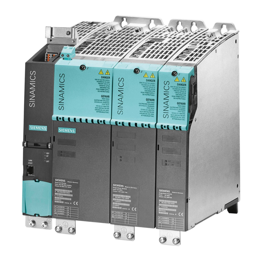
Siemens Sinamics S120 Manual
Booksize power units
Hide thumbs
Also See for Sinamics S120:
- Function manual (1094 pages) ,
- Diagnostic manual (947 pages) ,
- Manual (826 pages)
Table of Contents
Advertisement
Quick Links
Advertisement
Table of Contents

Related Manuals for Siemens Sinamics S120


Summary of Contents for Siemens Sinamics S120
- Page 3 ___________________ Booksize Power Units Preface ___________________ Fundamental safety instructions ___________________ System overview SINAMICS Line connection and line-side ___________________ power components S120 ___________________ Booksize Power Units Line Modules Booksize Line Modules Booksize ___________________ Compact Manual ___________________ Motor Modules Booksize Motor Modules Booksize ___________________ Compact ___________________...
- Page 4 Note the following: WARNING Siemens products may only be used for the applications described in the catalog and in the relevant technical documentation. If products and components from other manufacturers are used, these must be recommended or approved by Siemens. Proper transport, storage, installation, assembly, commissioning, operation and maintenance are required to ensure that the products operate safely and without any problems.
-
Page 5: Preface
My Documentation Manager Under the following link there is information on how to create your own individual documentation based on Siemens' content, and adapt it for your own machine documentation: http://www.siemens.com/mdm Training... - Page 6 Equipment for Machine Tools (Catalog NC 61) SINUMERIK 840D sl Type 1B • Equipment for Machine Tools (Catalog NC 62) Installation/assembly SINAMICS S120 Equipment Manual for Control Units and • Additional System Components SINAMICS S120 Equipment Manual for Booksize Power •...
- Page 7 EC Declaration of Conformity The EC Declarations of Conformity for the machinery directive can be found on the Internet http://support.automation.siemens.com/WW/view/de/21901735/67385845 Alternatively, you can contact the Siemens office in your region in order to obtain the EC Declaration of Conformity. Booksize Power Units...
- Page 8 EMC Installation Guideline Configuration Manual. The final statement regarding compliance with the standard is given by the respective label attached to the individual unit. Spare parts Spare parts are available on the Internet at: http://support.automation.siemens.com/WW/view/de/16612315 Booksize Power Units Manual, (GH2), 04/2014, 6SL3097-4AC00-0BP6...
- Page 9 Test certificates for functional safety functions ("Safety Integrated") can be found at: http://support.automation.siemens.com An up-to-date list of currently certified components is also available on request from your local Siemens office. If you have any questions relating to certifications that have not yet been completed, please ask your Siemens contact. Grounding symbols...
- Page 10 Preface Booksize Power Units Manual, (GH2), 04/2014, 6SL3097-4AC00-0BP6...
-
Page 11: Table Of Contents
Residual risks of power drive systems ..................30 System overview ........................... 33 Field of application ........................33 Platform Concept and Totally Integrated Automation ..............34 Introduction ..........................36 SINAMICS S120 components ...................... 38 2.4.1 Overview of Line Modules ......................40 2.4.2 Overview of Motor Modules ......................43 System data .......................... - Page 12 Table of contents 3.7.4.3 Dimension drawings ........................71 3.7.4.4 Technical data ..........................75 3.7.5 Basic Line Filter for Basic Line Modules ..................76 3.7.5.1 Description ..........................76 3.7.5.2 Interface description ........................77 3.7.5.3 Dimension drawings ........................78 3.7.5.4 Technical specifications ......................80 3.7.6 Basic Line Filter for Smart Line Modules ..................
- Page 13 Table of contents 3.11.2 Operating line connection components on the line supply ............139 3.11.3 Operation of the line connection components via a transformer ..........140 3.11.3.1 Safety instructions for line connection components..............140 3.11.3.2 Line supply connection conditions for Line Modules ..............141 3.11.3.3 Dimensioning an isolating transformer / autotransformer for several loads ......
- Page 14 Table of contents 4.4.6 Mounting............................ 209 4.4.7 Technical data ........................... 212 4.4.7.1 Characteristics .......................... 214 Active Line Modules Liquid Cooled ................... 217 4.5.1 Description ..........................217 4.5.2 Interface description ........................218 4.5.2.1 Overview ........................... 218 4.5.2.2 X1 line connection ........................219 4.5.2.3 X21 EP terminals ........................
- Page 15 Table of contents 4.8.1 Description ..........................274 4.8.2 Safety instructions for Smart Line Modules Booksize..............274 4.8.3 Interface description ........................276 4.8.3.1 Overview ............................ 276 4.8.3.2 X1 line connection ........................279 4.8.3.3 X21 EP terminals ........................281 4.8.3.4 X22 digital inputs ........................284 4.8.3.5 X24 24 V terminal adapter ......................
- Page 16 Table of contents Line Modules Booksize Compact ......................345 Smart Line Modules Booksize Compact ................... 345 5.1.1 Description ..........................345 5.1.2 Safety instructions for Smart Line Modules Booksize Compact ..........345 5.1.3 Interface description ........................350 5.1.3.1 Overview ........................... 350 5.1.3.2 X1 line connection ........................
- Page 17 Table of contents 6.3.7 Technical data ..........................423 6.3.7.1 Single Motor Modules ........................ 423 6.3.7.2 Double Motor Modules ....................... 426 6.3.7.3 Characteristics ........................... 427 6.3.8 Technical data for Motor Modules Booksize with 300% overload ..........431 6.3.8.1 Single Motor Modules (300% overload) ..................431 6.3.8.2 Characteristics for Motor Modules Booksize with 300% overload ..........
- Page 18 Table of contents Meaning of LEDs ........................499 Dimension drawings ........................500 Mounting............................ 503 Technical data ........................... 505 7.8.1 Single Motor Modules ....................... 505 7.8.2 Double Motor Modules ......................506 7.8.3 Characteristics .......................... 508 DC link components ..........................513 Safety instructions for DC link components ................513 Braking Module Booksize ......................
- Page 19 Table of contents 8.4.6 Connection to the Basic Line Module 100 kW ................550 Capacitor Module ........................552 8.5.1 Description ..........................552 8.5.2 Safety instructions for Capacitor Modules ................. 552 8.5.3 Interface description ........................553 8.5.3.1 Overview ............................ 553 8.5.4 Dimension drawing ........................
- Page 20 Table of contents 10.2.6 Installation ..........................609 10.2.7 Electrical connection ......................... 611 10.2.7.1 Connecting signaling contact X3 ....................612 10.2.7.2 Connecting power cables (using the VPM 200 Dynamik as an example) ........ 613 10.2.8 Technical data ........................... 616 Accessories ............................617 11.1 Shield connecting plates for power supply and motor cables ...........
- Page 21 Table of contents 11.5.7 Technical specifications ......................678 11.6 DRIVE-CLiQ cabinet bushings ....................679 11.6.1 Description ..........................679 11.6.2 Interface description ........................680 11.6.2.1 Overview ............................ 680 11.6.3 Dimension drawings ........................681 11.6.4 Mounting ............................ 682 11.6.4.1 DRIVE-CLiQ cabinet bushing for cables with RJ45 connectors ..........682 11.6.4.2 DRIVE-CLiQ cabinet bushing for cables with M12 plug/socket ..........
- Page 22 Table of contents 12.8 Connection systems ........................731 12.8.1 DRIVE-CLiQ signal cables ......................731 12.8.1.1 Overview ........................... 731 12.8.1.2 DRIVE-CLiQ signal cables without 24 V DC cores ..............732 12.8.1.3 DRIVE-CLiQ signal cables MOTION-CONNECT with RJ45 connectors ........732 12.8.1.4 DRIVE-CLiQ signal cables MOTION-CONNECT with RJ45 plug and M12 socket ....733 12.8.1.5 Comparison of DRIVE-CLiQ signal cables ................
- Page 23 Table of contents 12.13.10 Typical power losses for Motor Modules ................... 793 Cooling circuit and coolant properties ....................795 13.1 Cooling circuit requirements ...................... 795 13.1.1 Technical cooling circuits ......................795 13.1.2 Cooling system requirements ....................796 13.1.3 Cooling circuit configuration ....................... 797 13.1.4 Installation ..........................
- Page 24 Table of contents Booksize Power Units Manual, (GH2), 04/2014, 6SL3097-4AC00-0BP6...
-
Page 25: Fundamental Safety Instructions
Fundamental safety instructions General safety instructions DANGER Danger to life due to live parts and other energy sources Death or serious injury can result when live parts are touched. • Only work on electrical devices when you are qualified for this job. •... - Page 26 Fundamental safety instructions 1.1 General safety instructions WARNING Danger to life when live parts are touched on damaged devices Improper handling of devices can cause damage. For damaged devices, hazardous voltages can be present at the enclosure or at exposed components;...
- Page 27 Fundamental safety instructions 1.1 General safety instructions WARNING Danger to life through unexpected movement of machines when using mobile wireless devices or mobile phones Using mobile wireless devices or mobile phones with a transmit power > 1 W closer than approx.
-
Page 28: Safety Instructions For Electromagnetic Fields (Emf)
Fundamental safety instructions 1.2 Safety instructions for electromagnetic fields (EMF) NOTICE Device damage caused by incorrect voltage/insulation tests Incorrect voltage/insulation tests can damage the device. • Before carrying out a voltage/insulation check of the system/machine, disconnect the devices as all converters and motors have been subject to a high voltage test by the manufacturer, and therefore it is not necessary to perform an additional test within the system/machine. -
Page 29: Handling Electrostatic Sensitive Devices (Esd)
Note Industrial security Siemens provides automation and drive products with industrial security functions that support the secure operation of plants or machines. They are an important component in a holistic industrial security concept. With this in mind, our products undergo continuous development. -
Page 30: Residual Risks Of Power Drive Systems
• Keep the software up to date. Information and newsletters can be found at: http://support.automation.siemens.com • Incorporate the automation and drive components into a state-of-the-art, integrated industrial security concept for the installation or machine. For more detailed information, go to: http://www.siemens.com/industrialsecurity... - Page 31 Fundamental safety instructions 1.5 Residual risks of power drive systems 2. In the event of a fault, exceptionally high temperatures, including an open fire, as well as emissions of light, noise, particles, gases, etc. can occur inside and outside the inverter, e.g.: –...
- Page 32 Fundamental safety instructions 1.5 Residual risks of power drive systems Booksize Power Units Manual, (GH2), 04/2014, 6SL3097-4AC00-0BP6...
-
Page 33: System Overview
System overview Field of application SINAMICS is the family of drives from Siemens designed for machine and plant engineering applications. SINAMICS offers solutions for all drive tasks: ● Simple pump and fan applications in the process industry. ● Complex single drives in centrifuges, presses, extruders, elevators, as well as conveyor and transport systems ●... -
Page 34: Platform Concept And Totally Integrated Automation
SINAMICS S120 supports as standard PROFIBUS DP, the standard fieldbus for the TIA concept. It provides a high-performance, system-wide communication network which links all automation components: ●... - Page 35 System overview 2.2 Platform Concept and Totally Integrated Automation Figure 2-2 SINAMICS as part of the Siemens modular automation system Booksize Power Units Manual, (GH2), 04/2014, 6SL3097-4AC00-0BP6...
-
Page 36: Introduction
SINAMICS S120 system overview Modular system for sophisticated drive tasks SINAMICS S120 solves complex drive tasks for a wide range of industrial applications and is, therefore, designed as a modular system. Users can choose from many different harmonized components and functions to create a solution that best meets their requirements. - Page 37 Electronic rating plates in all components An important digital linkage element of the SINAMICS S120 drive system are the electronic type plates integrated in every component. They allow all drive components to be detected automatically via a DRIVE-CLiQ link. As a result, data does not have to be entered manually during commissioning or component replacement –...
-
Page 38: Sinamics S120 Components
System overview 2.4 SINAMICS S120 components SINAMICS S120 components Figure 2-4 Overview of SINAMICS S120 components Booksize Power Units Manual, (GH2), 04/2014, 6SL3097-4AC00-0BP6... - Page 39 ● Standardized design, side-by-side mounting Note Installation location in the cabinet The SINAMICS S120 components must always be mounted vertically in the cabinet. Other permissible installation locations are given in the descriptions for the individual components. Booksize format Booksize format units are optimized for multi-axis applications and are mounted adjacent to one another.
-
Page 40: Overview Of Line Modules
System overview 2.4 SINAMICS S120 components 2.4.1 Overview of Line Modules Line Modules generate a DC voltage from the connected rated voltage that is used to power the Motor Modules. All Basic Line Modules and Active Line Modules as well as the 16 kW, 36 kW, and 55 kW Smart Line Modules are equipped with DRIVE-CLiQ interfaces for communicating with the Control Unit. - Page 41 System overview 2.4 SINAMICS S120 components General characteristics of the Line Modules ● Supply voltage, 3 AC 380 V to 480 V ±10 % (-15 % <1 min), 47 to 63 Hz ● Suitable for TN, TT, and IT supply systems ●...
- Page 42 System overview 2.4 SINAMICS S120 components Frequency with which the DC link is precharged The frequency with which the DC link capacitance is precharged via the Line Module is determined using the following formula: The DC link capacitances of the individual components can be taken from the relevant technical data.
-
Page 43: Overview Of Motor Modules
System overview 2.4 SINAMICS S120 components 2.4.2 Overview of Motor Modules The Motor Modules in the SINAMICS S system in booksize format are inverters. They make the energy from the connected motors' DC link available at an adjusted voltage and with variable frequency. - Page 44 System overview 2.4 SINAMICS S120 components Characteristics of the Motor Modules: ● Single type from 3 A to 200 A ● Double type from 1.7 A to 18 A ● Internal/external air cooling ● Liquid cooling and cold plate cooling ●...
-
Page 45: System Data
System overview 2.5 System data System data Unless explicitly specified otherwise, the following technical data is valid for components of the SINAMICS S120 booksize drive system. Table 2- 1 Electrical data Line connection voltage 3 AC 380 … 480 V ±10 % (-15 % < 1 min) Line frequency 47 …... - Page 46 System overview 2.5 System data Table 2- 3 Environmental conditions Degree of protection IPXXB acc. to EN 60529, open type according to UL508 Protection class, line supply circuits I (with protective conductor connection) Electronic circuits safety extra-low voltage PELV / SELV Permissible cooling medium temperature (air) and 0°...
-
Page 47: Derating As A Function Of The Installation Altitude And Ambient Temperature
System overview 2.6 Derating as a function of the installation altitude and ambient temperature Derating as a function of the installation altitude and ambient temperature The Booksize power units are designed for operation at an ambient temperature of 0° C to 40°... - Page 48 System overview 2.6 Derating as a function of the installation altitude and ambient temperature Booksize Power Units Manual, (GH2), 04/2014, 6SL3097-4AC00-0BP6...
-
Page 49: Line Connection And Line-Side Power Components
Line connection and line-side power components Introduction The following components should be used to connect a SINAMICS S120 drive line-up in booksize format to the power supply: ● Disconnector unit (for Active Line Modules, Basic Line Modules, Smart Line Modules) ●... -
Page 50: Information On The Disconnector Unit
Line connection and line-side power components 3.2 Information on the disconnector unit Figure 3-2 Overview diagram, line connection with line filter and line reactor Information on the disconnector unit Disconnector units for Active Line Modules, Basic Line Modules, and Smart Line Modules A disconnector unit is required for disconnecting the drive line-up from the supply system correctly. -
Page 51: Overcurrent Protection By Means Of Line Fuses And Circuit Breakers
Line connection and line-side power components 3.3 Overcurrent protection by means of line fuses and circuit breakers Overcurrent protection by means of line fuses and circuit breakers Line fuses or circuit breakers must be used for cable protection/overcurrent protection. NH, D, and DO type fuses with a gL characteristic or suitable circuit breakers according to IEC 60947 can be used for this purpose. - Page 52 Line connection and line-side power components 3.3 Overcurrent protection by means of line fuses and circuit breakers Table 3- 3 Recommended line fuses and circuit breakers for Smart Line Modules booksize and booksize compact format 5 kW 10 kW 16 kW 36 kW 55 kW fuse...
-
Page 53: Line Supply Connection Via Residual-Current Devices
Line connection and line-side power components 3.4 Line supply connection via residual-current devices Line supply connection via residual-current devices Selectively tripping, AC/DC-sensitive residual-current devices (type B) can be used in addition to the overcurrent protection devices. Residual-current devices have to be installed if the power supply conditions in terms of short- circuit power and loop impedance at the infeed point are not such that the installed overcurrent protection devices will trip within the prescribed period if a fault occurs. - Page 54 Connecting a residual-current operated circuit breaker Recommendation SIEMENS selectively switching AC/DC-sensitive residual-current circuit-breakers according to EN 61009-1 of the 5SM series (e.g. 5SM3646-5 or 5SM3646-5+5SW3300 with an auxiliary disconnector (1 NC contact / 1 NO contact) for a rated current of 63 A and rated fault current of 0.3 A (see Catalog "BETA Modular Installation Devices - ET B1")).
-
Page 55: Residual-Current Monitors (Rcm)
Line connection and line-side power components 3.4 Line supply connection via residual-current devices 3.4.2 Residual-current monitors (RCM) Used in conjunction with appropriate circuit breakers, residual-current monitors (RCMs) provide fire and system protection even at high levels of grounding resistance (in TT systems, for example). - Page 56 Line connection and line-side power components 3.4 Line supply connection via residual-current devices Figure 3-4 Connecting a differential current monitoring device Recommendation ● AC/DC-sensitive differential current monitoring device RCMA423-D-2, Bender company, the 230 V supply voltage is tapped using an upstream isolating transformer ●...
-
Page 57: Overvoltage Protection
Line connection and line-side power components 3.5 Overvoltage protection Overvoltage protection To protect the units against line-side surge voltages, you are advised to install an overvoltage protection device directly at the infeed point (upstream of the main switch). To comply with the requirements of CSA C22.2 No. 14-05, a type VZCA or VZCA2 surge arrester is absolutely mandatory. -
Page 58: Line Filters
Line connection and line-side power components 3.7 Line filters Line filters 3.7.1 Safety instructions for line filters WARNING Danger to life if the fundamental safety instructions and remaining risks are not carefully observed If the fundamental safety instructions and remaining risks in Chapter 1 (Page 25) are not observed, accidents involving severe injuries or death may occur. - Page 59 Line connection and line-side power components 3.7 Line filters WARNING Fire hazard due to overheating because of inadequate ventilation clearances Inadequate ventilation clearances cause overheating with a risk for personnel through smoke development and fire. Damage can still occur on the line filter. •...
-
Page 60: Overview Of Line Filters
Line filter ranges that are coordinated with the different power stages are available for the SINAMICS S120 drive system. These line filters differ with regard to the frequency range in which they reduce the conducted emissions. - Page 61 Line connection and line-side power components 3.7 Line filters The line filter versions listed below are available for use with Line Modules. Table 3- 4 Overview of line filters Order number Basic Line Filter for Active Line Modules with line reactor 16 kW 6SL3000-0BE21-6DAx 36 kW...
-
Page 62: Basic Line Filters For Active Line Modules
Line connection and line-side power components 3.7 Line filters 3.7.3 Basic Line Filters for Active Line Modules 3.7.3.1 Description Basic Line Filters for Active Line Modules are designed to attenuate conducted interference emissions in accordance with the specifications contained in the relevant EMC directive. They are mainly effective in the frequency range from 150 kHz to 30 MHz;... -
Page 63: Interface Description
Line connection and line-side power components 3.7 Line filters Maximum total cable length = Σ motor cables, mains supply conductor from line filter to Line Module 3.7.3.2 Interface description Overview Figure 3-5 Interface overview, Basic Line Filter for Active Line Modules (example: 16 kW) Either the upper or lower PE screw can be used for the connection. -
Page 64: Dimension Drawings
Line connection and line-side power components 3.7 Line filters Line/load connection Table 3- 5 Line and load connection, Basic Line Filter for Active Line Modules 6SL3000-0BE21- 6SL3000-0BE23- 6SL3000-0BE25- 6SL3000-0BE28- 6SL3000-0BE31- 6DAx 6DA1 5DAx 0DAx 2DAx Rated power [kW] Line supply Screw terminals: Screw terminals: Screw terminals:... - Page 65 Line connection and line-side power components 3.7 Line filters Figure 3-7 Dimension drawing of Basic Line Filter for Active Line Modules 36 kW, all data in mm and (inches) Booksize Power Units Manual, (GH2), 04/2014, 6SL3097-4AC00-0BP6...
- Page 66 Line connection and line-side power components 3.7 Line filters Figure 3-8 Dimension drawing of Basic Line Filter for Active Line Modules 55 kW, all data in mm and (inches) Booksize Power Units Manual, (GH2), 04/2014, 6SL3097-4AC00-0BP6...
-
Page 67: Technical Data
Line connection and line-side power components 3.7 Line filters Figure 3-9 Dimension drawing of Basic Line Filter for Active Line Modules 80 kW and 120 kW, all dimensions in mm and (inches) 3.7.3.4 Technical data Table 3- 6 Technical data of the Basic Line Filter for Active Line Modules with Active Interface Module 6SL3000- 0BE21-6DAx 0BE23-6DA1... -
Page 68: Wideband Line Filter For Active Line Modules
Line connection and line-side power components 3.7 Line filters 3.7.4 Wideband Line Filter for Active Line Modules 3.7.4.1 Description Wideband Line Filters for Active Line Modules are mainly effective in the frequency range from 150 kHz to 30 MHz; this is the range relevant to ensure compliance with the appropriate standard. -
Page 69: Interface Description
Line connection and line-side power components 3.7 Line filters 3.7.4.2 Interface description Figure 3-10 Interface overview, Wideband Line Filter for Active Line Modules (example: 16 kW) NOTICE Damage caused by overheating as a result of an inadmissible mounting position If the component is not operated in a vertical position with the line supply terminals at the bottom, then the component can be damaged. - Page 70 Line connection and line-side power components 3.7 Line filters Line/load connection Table 3- 7 Line and load connection, Wideband Line Filter for Active Line Modules 6SL3000-0BE21- 6SL3000-0BE23- 6SL3000-0BE25- 6SL3000-0BE28- 6SL3000-0BE31- 6AAx 6AAx 5AAx 0AAx 2AAx Rated power [kW] Line supply Screw terminals: Screw terminals Screw terminals...
-
Page 71: Dimension Drawings
Line connection and line-side power components 3.7 Line filters 3.7.4.3 Dimension drawings Figure 3-11 Dimension drawing of Wideband Line Filter 16 kW for Active Lines Modules, all dimensions in mm and (inches) Booksize Power Units Manual, (GH2), 04/2014, 6SL3097-4AC00-0BP6... - Page 72 Line connection and line-side power components 3.7 Line filters Figure 3-12 Dimension drawing of Wideband Line Filter 36 kW for Active Lines Modules, all dimensions in mm and (inches) Booksize Power Units Manual, (GH2), 04/2014, 6SL3097-4AC00-0BP6...
- Page 73 Line connection and line-side power components 3.7 Line filters Figure 3-13 Dimension drawing of Wideband Line Filter 55 kW for Active Lines Modules, all dimensions in mm and (inches) Booksize Power Units Manual, (GH2), 04/2014, 6SL3097-4AC00-0BP6...
- Page 74 Line connection and line-side power components 3.7 Line filters Figure 3-14 Dimension drawing of Wideband Line Filter 80 kW for Active Lines Modules, all dimensions in mm and (inches) Booksize Power Units Manual, (GH2), 04/2014, 6SL3097-4AC00-0BP6...
-
Page 75: Technical Data
Line connection and line-side power components 3.7 Line filters Figure 3-15 Dimension drawing of Wideband Line Filter 120 kW for Active Lines Modules, all dimensions in mm and (inches) 3.7.4.4 Technical data Table 3- 8 Technical data: Wideband Line Filter for Active Line Modules 6SL3000 0BE21-6AAx 0BE23-6AAx... -
Page 76: Basic Line Filter For Basic Line Modules
Line connection and line-side power components 3.7 Line filters 3.7.5 Basic Line Filter for Basic Line Modules 3.7.5.1 Description Basic Line Filters for Basic Line Modules are designed to attenuate conducted interference emissions in accordance with the specifications contained in the relevant EMC legislation. They are mainly effective in the frequency range from 150 kHz to 30 MHz;... -
Page 77: Interface Description
Line connection and line-side power components 3.7 Line filters 3.7.5.2 Interface description Overview Figure 3-16 Interface overview, Basic Line Filter for Basic Line Modules (example: 40 kW) Either the upper or lower PE screw can be used for the connection. One of the screws remains unused. -
Page 78: Dimension Drawings
Line connection and line-side power components 3.7 Line filters Line/load connection Table 3- 9 Line and load connection, Basic Line Filter for Basic Line Modules 6SL3000-0BE21-6DAx 6SL3000-0BE23-6DA1 6SL3000-0BE31-2DAx Rated power [kW] Line supply connection Screw terminals Screw terminals Screw terminals L1, L2, L3 10 mm , 3 pole... - Page 79 Line connection and line-side power components 3.7 Line filters Figure 3-18 Dimension drawing of Basic Line Filter for Basic Line Modules 40 kW, all data in mm and (inches) Booksize Power Units Manual, (GH2), 04/2014, 6SL3097-4AC00-0BP6...
-
Page 80: Technical Specifications
Line connection and line-side power components 3.7 Line filters Figure 3-19 Dimension drawing of Basic Line Filter for Basic Line Modules 100 kW, all data in mm and (inches) 3.7.5.4 Technical specifications Table 3- 10 Technical data for Basic Line Filter for Basic Line Modules 6SL3000- 0BE21-6DAx 0BE23-6DA1... -
Page 81: Basic Line Filter For Smart Line Modules
Line connection and line-side power components 3.7 Line filters 3.7.6 Basic Line Filter for Smart Line Modules 3.7.6.1 Description Basic Line Filters for Smart Line Modules are designed to attenuate conducted interference emissions in accordance with the specifications contained in the relevant EMC legislation. They are mainly effective in the frequency range from 150 kHz to 30 MHz;... -
Page 82: Interface Description
Line connection and line-side power components 3.7 Line filters 3.7.6.2 Interface description Overview Figure 3-20 Interface overview, Basic Line Filter for Smart Line Modules (example: 36 kW) Either the upper or lower PE screw can be used for the connection. One of the screws remains unused. -
Page 83: Dimension Drawings
Line connection and line-side power components 3.7 Line filters Line/load connection Table 3- 11 Line and load connection, Basic Line Filter for Smart Line Modules 6SL3000-0HE15- 6SL3000-0HE21- 6SL3000-0BE21- 6SL3000-0BE23- 6SL3000-0BE25- 0AAx 0AAx 6DAx 6DA1 5DAx Rated power [kW] Line supply Screw terminals Screw terminals Screw terminals... - Page 84 Line connection and line-side power components 3.7 Line filters Figure 3-22 Dimension drawing of Basic Line Filter for Smart Line Modules 16 kW, all data in mm and (inches) Figure 3-23 Dimension drawing of Basic Line Filter for Smart Line Modules 36 kW, all data in mm and (inches) Booksize Power Units Manual, (GH2), 04/2014, 6SL3097-4AC00-0BP6...
-
Page 85: Technical Specifications
Line connection and line-side power components 3.7 Line filters Figure 3-24 Dimension drawing of Basic Line Filter for Smart Line Modules 55 kW, all data in mm and (inches) 3.7.6.4 Technical Specifications Table 3- 12 Technical data for: Basic Line Filter for Smart Line Modules 6SL3000- 0HE15-0AAx 0HE21-0AAx... -
Page 86: Line Reactors
Line connection and line-side power components 3.8 Line reactors Line reactors 3.8.1 Safety instructions for line reactors WARNING Danger to life if the fundamental safety instructions and remaining risks are not carefully observed If the fundamental safety instructions and remaining risks in Chapter 1 (Page 25) are not observed, accidents involving severe injuries or death may occur. - Page 87 Line connection and line-side power components 3.8 Line reactors NOTICE Damage to the system caused by line reactors that are not permissible Line reactors that are not permissible can damage the Line Modules. Line harmonics that damage/disturb other loads connected to the same line supply can also occur.
-
Page 88: Overview Of The Line Reactors
Line connection and line-side power components 3.8 Line reactors 3.8.2 Overview of the line reactors Line reactors limit line harmonics to permissible values. For this reason, line reactors should always be used. They must be used in conjunction with Active Line Modules as an energy storage feature for the step-up converter function. -
Page 89: Line Reactors For Active Line Modules
Line connection and line-side power components 3.8 Line reactors 3.8.3 Line reactors for Active Line Modules 3.8.3.1 Interface description Overview Figure 3-25 Interface overview, HFD line reactor 16 kW Figure 3-26 Interface overview, HFD line reactor 36 kW Booksize Power Units Manual, (GH2), 04/2014, 6SL3097-4AC00-0BP6... - Page 90 Line connection and line-side power components 3.8 Line reactors Figure 3-27 Interface overview, HFD line reactor 55 kW Figure 3-28 Interface overview, HFD line reactor 80 kW Booksize Power Units Manual, (GH2), 04/2014, 6SL3097-4AC00-0BP6...
- Page 91 Line connection and line-side power components 3.8 Line reactors Figure 3-29 Interface overview, HFD line reactor 120 kW Line/load connection Table 3- 14 Connection of HFD line reactors Order number 6SL3000-0DE21- 6SL3000-0DE23- 6SL3000-0DE25- 6SL3000-0DE28- 6SL3000-0DE31- 6AAx 6AAx 5AAx 0AAx 2AAx Power [kW] Line supply Screw terminal...
-
Page 92: Dimension Drawings
Line connection and line-side power components 3.8 Line reactors 3.8.3.2 Dimension drawings ① Terminal arrangement ② Warning label Figure 3-30 Dimension drawing of HFD line reactor 16 kW, all dimensions in mm and (inches) Booksize Power Units Manual, (GH2), 04/2014, 6SL3097-4AC00-0BP6... - Page 93 Line connection and line-side power components 3.8 Line reactors ① Terminal arrangement ② Warning label Figure 3-31 Dimension drawing of HFD line reactor 36 kW, all dimensions in mm and (inches) Booksize Power Units Manual, (GH2), 04/2014, 6SL3097-4AC00-0BP6...
- Page 94 Line connection and line-side power components 3.8 Line reactors ① Terminal arrangement Figure 3-32 Dimension drawing of HFD line reactor 55 kW, all dimensions in mm and (inches) Booksize Power Units Manual, (GH2), 04/2014, 6SL3097-4AC00-0BP6...
- Page 95 Line connection and line-side power components 3.8 Line reactors ① End retainers ② Terminal arrangement ③ Warning label Figure 3-33 Dimension drawing of HFD line reactor 80 kW, all dimensions in mm and (inches) Booksize Power Units Manual, (GH2), 04/2014, 6SL3097-4AC00-0BP6...
- Page 96 Line connection and line-side power components 3.8 Line reactors ① Transport eyebolts 10 x 25 mm (0.39 x 0.98 inch) ② Terminal arrangement ③ Warning label Figure 3-34 Dimension drawing of HFD line reactor 120 kW, all dimensions in mm and (inches) Booksize Power Units Manual, (GH2), 04/2014, 6SL3097-4AC00-0BP6...
-
Page 97: Technical Data
Line connection and line-side power components 3.8 Line reactors 3.8.3.3 Technical data Table 3- 15 Technical data for HFD line reactors 6SL3000– 6SL3000– 6SL3000– 6SL3000– 6SL3000- 0DE21- 0DE23- 0DE25- 0DE28- 0DE31- Unit 6AAx 6AAx 5AAx 0AAx 2AAx Power Rated current Power loss (see power loss tables) -
Page 98: Damping Resistor For Hfd Line Reactors
Line connection and line-side power components 3.8 Line reactors 3.8.4 Damping resistor for HFD line reactors 3.8.4.1 Description Using a damping resistor In some systems, oscillations can be generated which place an impermissibly high strain on the insulation systems of the motors and converters involved. Connecting a damping resistor to the additional winding of the HFD line reactor is an effective means of damping just such system oscillations. -
Page 99: Dimension Drawings
Line connection and line-side power components 3.8 Line reactors 3.8.4.3 Dimension drawings Figure 3-35 300 W damping resistor for HFD line reactors, all dimensions in mm and (inches) Booksize Power Units Manual, (GH2), 04/2014, 6SL3097-4AC00-0BP6... - Page 100 Line connection and line-side power components 3.8 Line reactors Figure 3-36 800 W damping resistor for HFD line reactors, all dimensions in mm and (inches) Booksize Power Units Manual, (GH2), 04/2014, 6SL3097-4AC00-0BP6...
- Page 101 Line connection and line-side power components 3.8 Line reactors Figure 3-37 1500 W damping resistor for HFD line reactors, all dimensions in mm and (inches) Booksize Power Units Manual, (GH2), 04/2014, 6SL3097-4AC00-0BP6...
-
Page 102: Technical Data
Line connection and line-side power components 3.8 Line reactors 3.8.4.4 Technical data Together with the HFD line reactor, an external resistor must be used for damping purposes (refer to Chapter Wiring with the HFD line reactor (Page 103)). Table 3- 16 Technical data for HFD damping resistors Order number 6SN1113-1AA00-0DAx... -
Page 103: Wiring With The Hfd Line Reactor
Line connection and line-side power components 3.8 Line reactors 3.8.4.5 Wiring with the HFD line reactor Figure 3-38 Wiring the HFD line reactor with a damping resistor Booksize Power Units Manual, (GH2), 04/2014, 6SL3097-4AC00-0BP6... -
Page 104: Line Reactors For Basic Line Modules
Line connection and line-side power components 3.8 Line reactors 3.8.5 Line reactors for Basic Line Modules 3.8.5.1 Interface description Overview Figure 3-39 Interface overview, line reactor for Basic Line Modules (20 kW) Booksize Power Units Manual, (GH2), 04/2014, 6SL3097-4AC00-0BP6... - Page 105 Line connection and line-side power components 3.8 Line reactors Figure 3-40 Interface overview, line reactor for Basic Line Modules (40 kW) Figure 3-41 Interface overview, line reactor for Basic Line Modules (100 kW) Booksize Power Units Manual, (GH2), 04/2014, 6SL3097-4AC00-0BP6...
- Page 106 Line connection and line-side power components 3.8 Line reactors Line/load connection Table 3- 17 Line and load connection line reactors for Basic Line Modules 6SL3000-0CE22-0AAx 6SL3000-0CE24-0AAx 6SL3000-0CE31-0AAx Power 20 kW 40 kW 100 kW Line supply connection Screw terminals Screw terminals Copper busbars with 8.5 mm 1U1, 1V1, 1W1 10 mm...
-
Page 107: Dimension Drawings
Line connection and line-side power components 3.8 Line reactors 3.8.5.2 Dimension drawings Figure 3-42 Dimension drawing of line reactor for Basic Line Module 20 kW, all dimensions in mm and (inches) Booksize Power Units Manual, (GH2), 04/2014, 6SL3097-4AC00-0BP6... - Page 108 Line connection and line-side power components 3.8 Line reactors Figure 3-43 Dimension drawing of line reactor for Basic Line Module 40 kW, all dimensions in mm and (inches) Booksize Power Units Manual, (GH2), 04/2014, 6SL3097-4AC00-0BP6...
- Page 109 Line connection and line-side power components 3.8 Line reactors Figure 3-44 Dimension drawing of line reactor for Basic Line Module 100 kW, all dimensions in mm and (inches) Booksize Power Units Manual, (GH2), 04/2014, 6SL3097-4AC00-0BP6...
-
Page 110: Technical Data
Line connection and line-side power components 3.8 Line reactors 3.8.5.3 Technical data Table 3- 18 Technical data of line reactors for the Basic Line Modules 6SL3000-0CE22-0AAx 6SL3000-0CE24-0AAx 6SL3000-0CE31-0AAx Unit Power Rated current Power loss (see power loss tables (Page 781)) Weight 11.2 21.7... -
Page 111: Line Reactors For Smart Line Modules
Line connection and line-side power components 3.8 Line reactors 3.8.6 Line reactors for Smart Line Modules 3.8.6.1 Interface description Figure 3-45 Interface overview, line reactors for Smart Line Modules (example: 36 kW) Booksize Power Units Manual, (GH2), 04/2014, 6SL3097-4AC00-0BP6... - Page 112 Line connection and line-side power components 3.8 Line reactors Figure 3-46 Interface overview, line reactors for Smart Line Modules (example: 55 kW) Line/load connection Table 3- 19 Line and load connection line reactors for Smart Line Modules 6SL3000-0CE15- 6SL3000-0CE21- 6SL3000-0CE21- 6SL3000-0CE23- 6SL3000-0CE25- 0AAx...
-
Page 113: Dimension Drawings
Line connection and line-side power components 3.8 Line reactors 3.8.6.2 Dimension drawings Figure 3-47 Dimension drawing of line reactor for Smart Line Modules 5 kW and 10 kW Table 3- 20 Dimensions of line reactors for Smart Line Modules (5 kW and 10 kW) Order number B [mm] b [mm]... - Page 114 Line connection and line-side power components 3.8 Line reactors Figure 3-48 Dimension drawing of line reactor for Smart Line Module 16 kW Booksize Power Units Manual, (GH2), 04/2014, 6SL3097-4AC00-0BP6...
- Page 115 Line connection and line-side power components 3.8 Line reactors Figure 3-49 Dimension drawing of line reactor for Smart Line Module 36 kW Booksize Power Units Manual, (GH2), 04/2014, 6SL3097-4AC00-0BP6...
-
Page 116: Technical Data
Line connection and line-side power components 3.8 Line reactors Figure 3-50 Dimension drawing of line reactor for Smart Line Module 55 kW, all dimensions in mm and (inches) 3.8.6.3 Technical data Table 3- 21 Technical data of line reactors for the Smart Line Module 6SL3000- 6SL3000- 6SL3000-... -
Page 117: Active Interface Modules Internal Air Cooling
Line connection and line-side power components 3.9 Active Interface Modules internal air cooling Active Interface Modules internal air cooling 3.9.1 Description Active Interface Modules are line-side interfaces for the Active Line Modules. They contain the following functional units: ● Line reactors ●... -
Page 118: Safety Instructions For Active Interface Modules
Line connection and line-side power components 3.9 Active Interface Modules internal air cooling 3.9.2 Safety instructions for Active Interface Modules WARNING Danger to life if the fundamental safety instructions and remaining risks are not carefully observed If the fundamental safety instructions and remaining risks in Chapter 1 (Page 25) are not observed, accidents involving severe injuries or death may occur. - Page 119 Line connection and line-side power components 3.9 Active Interface Modules internal air cooling WARNING Danger to life through electric shock due to unconnected cable shields Hazardous touch voltages can occur through capacitive cross-coupling due to unconnected cable shields. • As a minimum, connect cable shields and the cores of power cables that are not used (e.g.
-
Page 120: Interface Description
Line connection and line-side power components 3.9 Active Interface Modules internal air cooling 3.9.3 Interface description 3.9.3.1 Overview Figure 3-51 Interface overview, Active Interface Module 16 kW Booksize Power Units Manual, (GH2), 04/2014, 6SL3097-4AC00-0BP6... - Page 121 Line connection and line-side power components 3.9 Active Interface Modules internal air cooling Figure 3-52 Interface overview, Active Interface Module 36 kW Booksize Power Units Manual, (GH2), 04/2014, 6SL3097-4AC00-0BP6...
- Page 122 Line connection and line-side power components 3.9 Active Interface Modules internal air cooling Figure 3-53 Interface overview, Active Interface Module 55 kW Booksize Power Units Manual, (GH2), 04/2014, 6SL3097-4AC00-0BP6...
-
Page 123: Line/Load Connection
Line connection and line-side power components 3.9 Active Interface Modules internal air cooling Figure 3-54 Interface overview, Active Interface Module 80 kW and 120 kW 3.9.3.2 Line/load connection Table 3- 22 Line and load connection Active Interface Module 6SL3100-0BE21- 6SL3100-0BE23- 6SL3100-0BE25- 6SL3100-0BE28- 6SL3100-0BE31-... -
Page 124: X121 Temperature Sensor And Fan Control
Line connection and line-side power components 3.9 Active Interface Modules internal air cooling Note The connection terminals of the 36 kW Active Interface Module are only certain to be safe from touch protection according to EN 60529 if cables with a minimum cross-section of 25 mm²... -
Page 125: Connection Example
Line connection and line-side power components 3.9 Active Interface Modules internal air cooling Note The two "+" and "M" terminals are jumpered in the connector. This ensures the supply voltage is looped through. 3.9.4 Connection example Digital output (DO), controlled by the Control Unit Figure 3-55 Connection example: Active Interface Module Booksize Power Units... -
Page 126: Dimension Drawings
Line connection and line-side power components 3.9 Active Interface Modules internal air cooling 3.9.5 Dimension drawings Figure 3-56 Dimension drawing of Active Interface Module 16 kW, all dimensions in mm and (inches) Booksize Power Units Manual, (GH2), 04/2014, 6SL3097-4AC00-0BP6... - Page 127 Line connection and line-side power components 3.9 Active Interface Modules internal air cooling Figure 3-57 Dimension drawing of Active Interface Module 36 kW, all dimensions in mm and (inches) Booksize Power Units Manual, (GH2), 04/2014, 6SL3097-4AC00-0BP6...
- Page 128 Line connection and line-side power components 3.9 Active Interface Modules internal air cooling Figure 3-58 Dimension drawing of Active Interface Module 55 kW, all dimensions in mm and (inches) Booksize Power Units Manual, (GH2), 04/2014, 6SL3097-4AC00-0BP6...
- Page 129 Line connection and line-side power components 3.9 Active Interface Modules internal air cooling Figure 3-59 Dimension drawing of Active Interface Module 80 kW and 120 kW, all dimensions in mm and (inches) Booksize Power Units Manual, (GH2), 04/2014, 6SL3097-4AC00-0BP6...
-
Page 130: Installation
Line connection and line-side power components 3.9 Active Interface Modules internal air cooling 3.9.6 Installation The Active Interface Modules are designed for installation in the control cabinet. The Active Interface Modules should if possible be mounted directly next to the Active Line Module. ①... - Page 131 Line connection and line-side power components 3.9 Active Interface Modules internal air cooling ① Mounting panel ② M6 screws, Torx T30 (not hexagon-head screws) Figure 3-61 Installation of 36 kW Active Interface Module Booksize Power Units Manual, (GH2), 04/2014, 6SL3097-4AC00-0BP6...
- Page 132 Line connection and line-side power components 3.9 Active Interface Modules internal air cooling ① Mounting panel ② Washer ③ M6 screws, Torx T30 (not hexagon-head screws) Figure 3-62 Installation of 55 kW Active Interface Module Tightening torque for all screws: 6 Nm Table 3- 25 Protective conductor connection Active Interface Module...
-
Page 133: Operation On An Isolated-Neutral System (It System)
Line connection and line-side power components 3.9 Active Interface Modules internal air cooling 3.9.7 Operation on an isolated-neutral system (IT system) IT system In IT systems, all live parts are isolated from ground, or one point is connected to ground through an impedance. -
Page 134: Electrical Tests
Line connection and line-side power components 3.9 Active Interface Modules internal air cooling Remove the connection bracket to the Withdraw the connection bracket. Connection bracket for the noise suppression capacitor using a interference-suppression capacitor Tx25 screwdriver Note Installing the connection bracket for the interference-suppression capacitor For operation in other line supplies, the connection bracket must be reinstalled and fixed with a tightening torque of 1.8 Nm. -
Page 135: Technical Data
Line connection and line-side power components 3.9 Active Interface Modules internal air cooling 3.9.9 Technical data Table 3- 27 Technical data Active Interface Module 6SL3100- 0BE21-6ABx 0BE23-6ABx 0BE25-5ABx 0BE28-0ABx 0BE31-2ABx 16 kW 36 kW 55 kW 80 kW 120 kW rated Current requirement of 0,25... -
Page 136: Combining Line Reactors And Line Filters
Line connection and line-side power components 3.10 Combining line reactors and line filters 3.10 Combining line reactors and line filters Figure 3-63 Combining line reactors and line filters Booksize Power Units Manual, (GH2), 04/2014, 6SL3097-4AC00-0BP6... -
Page 137: Line Connection Variants
Line connection and line-side power components 3.11 Line connection variants 3.11 Line connection variants 3.11.1 Ways of connecting the line supply A distinction is made between the following line connection versions: ● Line connection components to be directly connected to the line supply ●... - Page 138 Line connection and line-side power components 3.11 Line connection variants Note Permissible line supplies In combination with the drive system, the motors are generally approved for operation on TN and TT systems with grounded neutral point and on IT systems. WARNING Fire hazard for the motor due to overload of the insulation There is higher stress on the motor insulation through a ground fault in an IT system or...
-
Page 139: Operating Line Connection Components On The Line Supply
Line connection and line-side power components 3.11 Line connection variants 3.11.2 Operating line connection components on the line supply The SINAMICS S Booksize converter system is rated for direct operation on TN, TT, and IT line supply systems with a rated voltage of 380 V 3 AC to 480 V 3 AC. Figure 3-65 Direct operation on the line supply Booksize Power Units... -
Page 140: Operation Of The Line Connection Components Via A Transformer
Line connection and line-side power components 3.11 Line connection variants 3.11.3 Operation of the line connection components via a transformer 3.11.3.1 Safety instructions for line connection components NOTICE Destruction or damage to additional loads as a result of undesirable line harmonics Line harmonics can occur if line filters that differ from those listed in this Manual are used. -
Page 141: Line Supply Connection Conditions For Line Modules
Line connection and line-side power components 3.11 Line connection variants 3.11.3.2 Line supply connection conditions for Line Modules Table 3- 28 Line supply connection conditions for Line Modules Module Description Basic Line Module Operation on line supplies from S ≥ 30 Kline Smart Line Module Operation on line supplies from S... -
Page 142: Dimensioning An Isolating Transformer / Autotransformer For Several Loads
Line connection and line-side power components 3.11 Line connection variants 3.11.3.3 Dimensioning an isolating transformer / autotransformer for several loads A SINAMICS Line Module and other loads/machines should be connected via an isolating transformer / autotransformer (matching transformer) to the line supply. The following diagram shows the connection using an isolating transformer as an example. - Page 143 Line connection and line-side power components 3.11 Line connection variants An isolating transformer / autotransformer (matching transformer) must be dimensioned for the total of all loads connected to it. The apparent power required for the Line Modules must be determined and added as indicated in table "Transformer configuration instructions". If the transformer is underdimensioned (S or S ), this can lead to increased line voltage dips and...
- Page 144 Line connection and line-side power components 3.11 Line connection variants Special case: When operating with only one supply at a transformer, the values may be reduced by the factor 0.73. ≥ 0.73 • 70 • P (for Active Line Module and Smart Line Module) K line ≥...
- Page 145 Line connection and line-side power components 3.11 Line connection variants Rated power of the used Required rated power of the Required short-circuit Minimum system fault level isolating transformer / voltage U required Active Module P autotransformer (70 • P Kline (1.27 •...
- Page 146 Line connection and line-side power components 3.11 Line connection variants > S ⇒ S is decisive. The matching transformer requires a rated power S of 21 kVA for a short-circuit voltage u of 1%. Example 3: If S is smaller, the transformer must be stronger. K plant matching transformer = 3%, = 3,000 kVA...
-
Page 147: Operating Line Connection Components Via An Autotransformer
Line connection and line-side power components 3.11 Line connection variants 3.11.3.4 Operating line connection components via an autotransformer An autotransformer can be used to adapt the voltage in the range up to 3-ph. 480 VAC +10%. DANGER Danger to life due to electric shock in the event that an isolating transformer is not used At high voltages an isolating transformer must be used in order to implement protective separation. - Page 148 Line connection and line-side power components 3.11 Line connection variants Figure 3-67 Operation of a Line Module via an autotransformer Booksize Power Units Manual, (GH2), 04/2014, 6SL3097-4AC00-0BP6...
-
Page 149: Operating Line Connection Components Via An Isolating Transformer
Line connection and line-side power components 3.11 Line connection variants 3.11.3.5 Operating line connection components via an isolating transformer An isolating transformer converts the line supply type of the plant or system (e.g. IT system) to a TN system. Additional voltage adaptation to the permissible voltage tolerance range is possible. - Page 150 Line connection and line-side power components 3.11 Line connection variants Figure 3-68 Operation of a Line Module via an isolating transformer Booksize Power Units Manual, (GH2), 04/2014, 6SL3097-4AC00-0BP6...
-
Page 151: Line Modules Booksize
Line Modules Booksize Safety instructions for Line Modules Booksize WARNING Danger to life if the fundamental safety instructions and remaining risks are not carefully observed If the fundamental safety instructions and remaining risks in Chapter 1 (Page 25) are not observed, accidents involving severe injuries or death may occur. - Page 152 This can result in serious injury or death. • Only use adapters (DC link adapters and DC link rectifier adapters) released by Siemens for the connection to the DC link. WARNING Danger to life through electric shock due to incorrectly installed DC link bridges Incorrectly installed DC link bridges at the left-hand end of the drive line-up can cause an electric shock.
- Page 153 Line Modules Booksize 4.1 Safety instructions for Line Modules Booksize WARNING Danger to life through electric shock due to missing DC link side covers There is a danger of an electric shock through contact when the side covers of the DC link are missing.
- Page 154 Damage or malfunctions can occur on the devices or system when DRIVE-CLiQ cables are used that are either incorrect or have not been approved for this purpose. • Only use suitable DRIVE-CLiQ cables that have been approved by Siemens for the particular application.
- Page 155 Line Modules Booksize 4.1 Safety instructions for Line Modules Booksize Special features for Line Modules with external air cooling Note Component failure due to the pollution of external heat sinks For components with external air cooling, the fan and the heat sinks can accumulate a lot of pollution.
-
Page 156: Active Line Modules With Internal Air Cooling
Line Modules Booksize 4.2 Active Line Modules with internal air cooling Active Line Modules with internal air cooling 4.2.1 Description Active Line Modules generate a constant, regulated DC voltage in the DC link from the 3- phase line supply voltage that supplies the connected Motor Modules with power. This ensures that they are not influenced by line voltage fluctuations. -
Page 157: Interface Description
Line Modules Booksize 4.2 Active Line Modules with internal air cooling 4.2.2 Interface description 4.2.2.1 Overview Figure 4-1 Interface overview, Active Line Module with internal air cooling (example: 16 kW) Booksize Power Units Manual, (GH2), 04/2014, 6SL3097-4AC00-0BP6... -
Page 158: X1 Line Connection
Line Modules Booksize 4.2 Active Line Modules with internal air cooling 4.2.2.2 X1 line connection Table 4- 1 X1: Line connection for Active Line Modules 16 kW Terminal Technical data Max. connectable cross-section: 10 mm Type: Screw terminal 6 (Page 755) Tightening torque: 1.5 …... -
Page 159: X12 Fan Connection
Type: Screw terminal 1 (Page 755) Max. cross-section that can be connected: 1.5 mm The temperature sensor type and the temperature output can be selected by parameter (see the SINAMICS S120/S150 List Manual). Temperatures are detected but not evaluated in the Active Line Module. - Page 160 Line Modules Booksize 4.2 Active Line Modules with internal air cooling Terminals X21.3 and X21.4 WARNING Danger to life when live parts are touched when terminals X21.3 and X21.4 are connected For operation, the 24 V DC voltage must be connected to terminal X21.3 and ground to terminal X21.4.
-
Page 161: X24 24 V Terminal Adapter
Line Modules Booksize 4.2 Active Line Modules with internal air cooling 4.2.2.5 X24 24 V terminal adapter Table 4- 5 X24: 24 V terminal adapter Terminal Designation Technical data 24 V power supply 24 V DC supply voltage Ground Electronics ground Type: Screw terminal 5 (Page 755) Max. -
Page 162: Connection Example
Line Modules Booksize 4.2 Active Line Modules with internal air cooling 4.2.3 Connection example Figure 4-2 Example connection of Active Line Module Note If you are using a VSM10 Voltage Sensing Module, the leading opening contact can be omitted. Booksize Power Units Manual, (GH2), 04/2014, 6SL3097-4AC00-0BP6... -
Page 163: Meaning Of Leds
Both options depend on the LED status when component recognition is activated. See SINAMICS S120/S150 List Manual for the parameters to activate the recognition of components via LED WARNING Danger of death when live parts of the DC link are touched Irrespective of the state of the LED "DC LINK", hazardous DC link voltages can be present. -
Page 164: Dimension Drawings
Line Modules Booksize 4.2 Active Line Modules with internal air cooling 4.2.5 Dimension drawings Figure 4-3 Dimension drawing of 16 kW Active Line Module with internal air cooling, all dimensions in mm and (inches) Note The shield connecting plate is supplied as standard with a 100 mm Line Module. For more information, see Chapter Shield connecting plates for power supply and motor cables (Page 617). - Page 165 Line Modules Booksize 4.2 Active Line Modules with internal air cooling Figure 4-4 Dimension drawing of 36 kW and 55 kW Active Line Modules with internal air cooling (example, 36 kW), all dimensions in mm and (inches) Table 4- 8 Dimensions of 36 kW and 55 kW Active Line Modules with internal air cooling Active Line Module Order number...
- Page 166 Line Modules Booksize 4.2 Active Line Modules with internal air cooling Figure 4-5 Dimension drawing of 80 kW and 120 kW Active Line Modules with internal air cooling, all dimensions in mm and (inches) Table 4- 9 Dimensions of 80 kW and 120 kW Active Line Modules with internal air cooling Active Line Module Order number B [mm] (inches)
- Page 167 Line Modules Booksize 4.2 Active Line Modules with internal air cooling Figure 4-6 Dimension drawing of fan for 80 kW and 120 kW Active Line Modules with internal air cooling, all dimensions in mm and (inches) Note The fans for the 80 kW and 120 kW Active Line Modules are included in the scope of delivery.
-
Page 168: Installation
Line Modules Booksize 4.2 Active Line Modules with internal air cooling 4.2.6 Installation Active Line Modules are designed for installation in the control cabinet. They are fixed to the control cabinet panel or a mounting panel using M6 screws. ① Control cabinet panel/mounting panel ②... - Page 169 Line Modules Booksize 4.2 Active Line Modules with internal air cooling Installing the sub-chassis fan Figure 4-8 Mounting the fan for Active Line Modules 80 kW and 120 kW 1. Fix the fan with M6 screws (tightening torque: 6 Nm). 2.
-
Page 170: Technical Data
Line Modules Booksize 4.2 Active Line Modules with internal air cooling 4.2.7 Technical data Table 4- 10 Technical data of Active Line Modules Internal air cooling 6SL3130– 7TE21–6AAx 7TE23–6AAx 7TE25–5AAx 7TE25–5AA3 + Active Interface Module Rated power Infeed Rated power (S1) kW (P Infeed power (S6 - 40 %) kW (P... - Page 171 Line Modules Booksize 4.2 Active Line Modules with internal air cooling Internal air cooling 6SL3130– 7TE21–6AAx 7TE23–6AAx 7TE25–5AAx 7TE25–5AA3 + Active Interface Module Rated power Circuit breaker See Section Overcurrent protection using line fuses and circuit (IEC 60947 and UL) breakers (Page 51) Rated short-circuit current SCCR...
- Page 172 Line Modules Booksize 4.2 Active Line Modules with internal air cooling Internal air cooling 6SL3130– 7TE28–0AAx 7TE31–2AAx Rated power DC link currents Rated DC link current: for 600 V: DC link current: for 600 V DC; for S6 - 40 % for 600 V DC;...
-
Page 173: Characteristics
Line Modules Booksize 4.2 Active Line Modules with internal air cooling 4.2.7.1 Characteristics Rated duty cycles for Active Line Modules Figure 4-9 Rated duty cycles for Active Line Modules (exception: not applicable for 55 kW Active Line Module with Active Interface Module) Booksize Power Units Manual, (GH2), 04/2014, 6SL3097-4AC00-0BP6... - Page 174 Line Modules Booksize 4.2 Active Line Modules with internal air cooling Rated duty cycles for Active Line Modules with Active Interface Modules Figure 4-10 Load cycles for 55 kW Active Line Modules with Active Interface Module Figure 4-11 Peak load cycle with initial load for 55 kW Active Line Modules with Active Interface Module Booksize Power Units Manual, (GH2), 04/2014, 6SL3097-4AC00-0BP6...
- Page 175 Line Modules Booksize 4.2 Active Line Modules with internal air cooling Derating characteristics Note For additional information, see chapter Derating as a function of the installation altitude and ambient temperature (Page 47). Figure 4-12 Output current as a function of the ambient temperature Figure 4-13 Output current as a function of the installation altitude Booksize Power Units...
-
Page 176: Active Line Modules With External Air Cooling
Line Modules Booksize 4.3 Active Line Modules with external air cooling Active Line Modules with external air cooling 4.3.1 Description The Motor Modules are connected to the power supply network via the Active Line Modules with external air cooling which provide the Motor Modules with a constant DC link voltage. This ensures that they are not influenced by line voltage fluctuations. -
Page 177: Interface Description
Line Modules Booksize 4.3 Active Line Modules with external air cooling 4.3.2 Interface description 4.3.2.1 Overview Figure 4-14 Interface overview, Active Line Module with external air cooling (example: 16 kW) Booksize Power Units Manual, (GH2), 04/2014, 6SL3097-4AC00-0BP6... -
Page 178: X1 Line Connection
Line Modules Booksize 4.3 Active Line Modules with external air cooling 4.3.2.2 X1 line connection Table 4- 12 X1: Line connection for Active Line Modules 16 kW Terminal Technical data Max. connectable cross-section: 10 mm Type: Screw terminal 6 (Page 755) Tightening torque: 1.5 …... -
Page 179: X12 Fan Connection
Type: Screw terminal 1 (Page 755) Max. cross-section that can be connected: 1.5 mm The temperature sensor type and the temperature output can be selected by parameter (see the SINAMICS S120/S150 List Manual). Temperatures are detected but not evaluated in the Active Line Module. - Page 180 Line Modules Booksize 4.3 Active Line Modules with external air cooling Terminals X21.3 and X21.4 WARNING Danger to life when live parts are touched when terminals X21.3 and X21.4 are connected For operation, the 24 V DC voltage must be connected to terminal X21.3 and ground to terminal X21.4.
-
Page 181: X24 24 V Terminal Adapter
Line Modules Booksize 4.3 Active Line Modules with external air cooling 4.3.2.5 X24 24 V terminal adapter Table 4- 16 X24: 24 V terminal adapter Terminal Designation Technical data 24 V power supply 24 V DC supply voltage Ground Electronics ground Type: Screw terminal 5 (Page 755) Max. -
Page 182: Connection Example
Line Modules Booksize 4.3 Active Line Modules with external air cooling 4.3.3 Connection example Figure 4-15 Example connection of Active Line Module Note If you are using a VSM10 Voltage Sensing Module, the leading opening contact can be omitted. Booksize Power Units Manual, (GH2), 04/2014, 6SL3097-4AC00-0BP6... -
Page 183: Meaning Of Leds
Both options depend on the LED status when component recognition is activated. See SINAMICS S120/S150 List Manual for the parameters to activate the recognition of components via LED WARNING Danger of death when live parts of the DC link are touched Irrespective of the state of the LED "DC LINK", hazardous DC link voltages can be present. -
Page 184: Dimension Drawings
Line Modules Booksize 4.3 Active Line Modules with external air cooling 4.3.5 Dimension drawings Figure 4-16 Dimension drawing of 16 kW Active Line Module with external air cooling, all dimensions in mm and (inches) Table 4- 19 Dimensions of 16 kW Active Line Module with external air cooling Active Line Module Order number B [mm] (inches) b [mm] (inches) - Page 185 Line Modules Booksize 4.3 Active Line Modules with external air cooling Figure 4-17 Dimension drawing of 36 kW, 55 kW, 80 kW, and 120 kW Active Line Modules with external air cooling (example 36 kW), all dimensions in mm and (inches) Table 4- 20 Dimensions of 36 kW, 55 kW, 80 kW, and 120 kW Active Line Modules with external air cooling Active Line...
- Page 186 Line Modules Booksize 4.3 Active Line Modules with external air cooling Figure 4-18 Dimension drawing of fan for 80 kW and 120 kW Active Line Modules with external air cooling, all dimensions in mm and (inches) Booksize Power Units Manual, (GH2), 04/2014, 6SL3097-4AC00-0BP6...
-
Page 187: Mounting
Line Modules Booksize 4.3 Active Line Modules with external air cooling 4.3.6 Mounting ① Mounting plate with openings for mounting ② M6 studs ③ M6 nut ④ Spring washer ⑤ Washer ⑥ Fan assembly Figure 4-19 Mounting an Active Line Module with external air cooling (example: 36 kW) Tightening torques: ●... - Page 188 Line Modules Booksize 4.3 Active Line Modules with external air cooling Help with the mechanical control cabinet design is available from: Siemens AG Industry Sector, IA DT MC MF - WKC AS TCCCC (Technical Competence Center Cabinets Chemnitz) Postfach 1124 09070 Chemnitz, Germany e-mail: cc.cabinetcooling.aud@siemens.com...
- Page 189 Line Modules Booksize 4.3 Active Line Modules with external air cooling ① Insert plate or mounting plate ② Cross-piece ③ Reinforcing bracket Figure 4-21 Openings to mount an Active Line Module 300 mm with external air cooling, all data in mm and (inches) Table 4- 21 Dimensions of openings to mount Active Line Modules with external air cooling Component width...
- Page 190 Line Modules Booksize 4.3 Active Line Modules with external air cooling ① Insert plate or mounting plate ② Threaded bolts M5 x 28 Figure 4-22 Example of a mounting plate for a drive line-up with external air cooling When mounting it must be ensured that the component's seal is tight throughout. The cross- pieces must have the appropriate stability.
- Page 191 Line Modules Booksize 4.3 Active Line Modules with external air cooling ① Mounting plate ② Cover ③ Rear panel ④ Air discharge ⑤ Air inlet - filter with filter fan ⑥ ⑥ To comply with degree of protection IP54, the surfaces between the mounting plate and the cabinet strip must be sealed all round.
- Page 192 Line Modules Booksize 4.3 Active Line Modules with external air cooling ① Insert plate ② Mounting plate ③ Cover ④ Rear panel ⑤ Air discharge ⑥ Air inlet - filter with filter fan ⑦ ⑦ To maintain the degree of protection IP54, the surfaces between the mounting plate and the cabinet strip as well as between the mounting plate and insert plate must be sealed all around.
-
Page 193: Technical Data
Line Modules Booksize 4.3 Active Line Modules with external air cooling Note If the cooling air requirement is not covered by the filtered fan, the components cannot output their specified power. The filters with filter fan must be regularly checked for dirt and cleaned if necessary. 4.3.7 Technical data Table 4- 22... - Page 194 Line Modules Booksize 4.3 Active Line Modules with external air cooling External air cooling 6SL3131– 7TE21–6AAx 7TE23–6AAx 7TE25–5AAx 7TE25–5AA3 + Active Interface Module Rated power Total power loss 282,8 945,6 945,6 (including electronics losses, see Power loss tables (Page 781)) Max.
- Page 195 Line Modules Booksize 4.3 Active Line Modules with external air cooling External air cooling 6SL3131– 7TE28–0AAx 7TE31-2AAx Rated power DC link voltage 510 … 720 Overvoltage trip 820 ± 2 % Undervoltage trip 360 ± 2 % Input currents Rated input current at AC 400 V: Input current at AC 380 V / AC 480 V...
-
Page 196: Characteristics
Line Modules Booksize 4.3 Active Line Modules with external air cooling 4.3.7.1 Characteristics Rated duty cycles for Active Line Modules Figure 4-25 Rated duty cycles for Active Line Modules (exception: not applicable for 55 kW Active Line Module with Active Interface Module) Booksize Power Units Manual, (GH2), 04/2014, 6SL3097-4AC00-0BP6... - Page 197 Line Modules Booksize 4.3 Active Line Modules with external air cooling Rated duty cycles for Active Line Modules with Active Interface Modules Figure 4-26 Load cycles for 55 kW Active Line Modules with Active Interface Module Figure 4-27 Peak load cycle with initial load for 55 kW Active Line Modules with Active Interface Module Booksize Power Units Manual, (GH2), 04/2014, 6SL3097-4AC00-0BP6...
- Page 198 Line Modules Booksize 4.3 Active Line Modules with external air cooling Derating characteristics Note For additional information, see chapter Derating as a function of the installation altitude and ambient temperature (Page 47). Figure 4-28 Output current as a function of the ambient temperature Figure 4-29 Output current as a function of the installation altitude Booksize Power Units...
-
Page 199: Active Line Modules With Cold Plate
Line Modules Booksize 4.4 Active Line Modules with cold plate Active Line Modules with cold plate 4.4.1 Description Active Line Modules generate a constant, regulated DC voltage in the DC link from the 3- phase line supply voltage that supplies the connected Motor Modules with power. This ensures that they are not influenced by line voltage fluctuations. -
Page 200: Interface Description
Line Modules Booksize 4.4 Active Line Modules with cold plate 4.4.2 Interface description 4.4.2.1 Overview Figure 4-30 Interface overview, Active Line Module with cold plate (example: 16 kW) Booksize Power Units Manual, (GH2), 04/2014, 6SL3097-4AC00-0BP6... -
Page 201: X1 Line Connection
Line Modules Booksize 4.4 Active Line Modules with cold plate 4.4.2.2 X1 line connection Table 4- 24 X1: Line connection for Active Line Modules 16 kW Terminal Technical data Max. connectable cross-section: 10 mm Type: Screw terminal 6 (Page 755) Tightening torque: 1.5 …... -
Page 202: X21 Ep Terminals
Type: Screw terminal 1 (Page 755) Max. cross-section that can be connected: 1.5 mm The temperature sensor type and the temperature output can be selected by parameter (see the SINAMICS S120/S150 List Manual). Temperatures are detected but not evaluated in the Active Line Module. -
Page 203: X24 24 V Terminal Adapter
Line Modules Booksize 4.4 Active Line Modules with cold plate NOTICE Damage to the drive electronics when switching the line contactor under load When switching the line contactor (type according to the recommended selection) under load, then the contacts will be subject to premature wear. This can cause the contactor to malfunction, with subsequent damage to the drive electronics. -
Page 204: X200-X202 Drive-Cliq Interfaces
Line Modules Booksize 4.4 Active Line Modules with cold plate 4.4.2.5 X200-X202 DRIVE-CLiQ interfaces Table 4- 28 X200-X202: DRIVE-CLiQ interfaces Signal name Technical data Transmit data + Transmit data - Receive data + Reserved, do not use Reserved, do not use Receive data - Reserved, do not use Reserved, do not use... -
Page 205: Connection Example
Line Modules Booksize 4.4 Active Line Modules with cold plate 4.4.3 Connection example Figure 4-31 Connection example: Active Line Module with cold plate Note If you are using a VSM10 Voltage Sensing Module, the leading opening contact can be omitted. Booksize Power Units Manual, (GH2), 04/2014, 6SL3097-4AC00-0BP6... -
Page 206: Meaning Of Leds
Both options depend on the LED status when component recognition is activated. See SINAMICS S120/S150 List Manual for the parameters to activate the recognition of components via LED WARNING Danger of death when live parts of the DC link are touched Irrespective of the state of the LED "DC LINK", hazardous DC link voltages can be present. -
Page 207: Dimension Drawings
Line Modules Booksize 4.4 Active Line Modules with cold plate 4.4.5 Dimension drawings Figure 4-32 Dimension drawing of 16 kW Active Line Module with cold plate, all dimensions in mm and (inches) Table 4- 30 Dimensions of 16 kW Active Line Module with cold plate Active Line Module Order number B [mm] (inches) - Page 208 Line Modules Booksize 4.4 Active Line Modules with cold plate Figure 4-33 Dimension drawing of 36 kW, 55 kW, 80 kW, and 120 kW Active Line Modules with cold plate, all dimensions in mm and (inches) Table 4- 31 Dimensions of 36 kW, 55 kW, 80 kW, and 120 kW Active Line Modules with cold plate Active Line Module Order number B [mm] (inches)
-
Page 209: Mounting
Note the mounting position of the heat-conducting foil (see diagram below). Note • Also replace the heat-conducting foil when replacing a component. • Only use heat-conducting foil released or supplied by Siemens. Table 4- 32 Overview of heat-conducting foils Order number... - Page 210 Line Modules Booksize 4.4 Active Line Modules with cold plate Mounting ① External heat sink (air or liquid) ② M6 studs ③ Heat-conducting foil ④ Cold plate ⑤ M6 nut ⑥ Spring washer ⑦ Washer Figure 4-34 Mounting an Active Line Module with cold plate on an external heat sink (example: 36 Tightening torques: ●...
- Page 211 Line Modules Booksize 4.4 Active Line Modules with cold plate Help with the mechanical control cabinet design is available from: Siemens AG Industry Sector, IA DT MC MF - WKC AS TCCCC (Technical Competence Center Cabinets Chemnitz) Postfach 1124 09070 Chemnitz, Germany e-mail: cc.cabinetcooling.aud@siemens.com...
-
Page 212: Technical Data
Line Modules Booksize 4.4 Active Line Modules with cold plate 4.4.7 Technical data Table 4- 33 Technical data for Active Line Modules with cold plate cooling Cold plate 6SL3136- 21-6AAx 23-6AAx 25-5AAx 25-5AA3 + 28-0AAx 31-2AAx Active Interface Module Rated power 80 (64) 120 (84) Infeed... - Page 213 Line Modules Booksize 4.4 Active Line Modules with cold plate Cold plate 6SL3136- 21-6AAx 23-6AAx 25-5AAx 25-5AA3 + 28-0AAx 31-2AAx Active Interface Module DC link capacitance Active Line Module μF 1410 1880 1880 2820 3760 Drive line-up, max. μF 20000 20000 20000 20000...
-
Page 214: Characteristics
Line Modules Booksize 4.4 Active Line Modules with cold plate 4.4.7.1 Characteristics Rated duty cycles for Active Line Modules Figure 4-35 Rated duty cycles for Active Line Modules (exception: not applicable for 55 kW Active Line Module with Active Interface Module) Booksize Power Units Manual, (GH2), 04/2014, 6SL3097-4AC00-0BP6... - Page 215 Line Modules Booksize 4.4 Active Line Modules with cold plate Rated duty cycles for Active Line Modules with Active Interface Modules Figure 4-36 Load cycles for 55 kW Active Line Modules with Active Interface Module Figure 4-37 Peak load cycle with initial load for 55 kW Active Line Modules with Active Interface Module Booksize Power Units Manual, (GH2), 04/2014, 6SL3097-4AC00-0BP6...
- Page 216 Line Modules Booksize 4.4 Active Line Modules with cold plate Derating characteristics Note For additional information, see chapter Derating as a function of the installation altitude and ambient temperature (Page 47). Figure 4-38 Output current as a function of the ambient temperature Figure 4-39 Output current as a function of the installation altitude Booksize Power Units...
-
Page 217: Active Line Modules Liquid Cooled
Line Modules Booksize 4.5 Active Line Modules Liquid Cooled Active Line Modules Liquid Cooled 4.5.1 Description Active Line Modules generate a constant, regulated DC voltage in the DC link from the 3- phase line supply voltage that supplies the connected Motor Modules with power. This ensures that they are not influenced by line voltage fluctuations. -
Page 218: Interface Description
Line Modules Booksize 4.5 Active Line Modules Liquid Cooled 4.5.2 Interface description 4.5.2.1 Overview Figure 4-40 Interface overview, Active Line Module Liquid Cooled (120 kW) Booksize Power Units Manual, (GH2), 04/2014, 6SL3097-4AC00-0BP6... -
Page 219: X1 Line Connection
Type: Screw terminal 1 (Page 755) Max. cross-section that can be connected: 1.5 mm The temperature sensor type and the temperature output can be selected by parameter (see the SINAMICS S120/S150 List Manual). Temperatures are detected but not evaluated in the Active Line Module. - Page 220 Line Modules Booksize 4.5 Active Line Modules Liquid Cooled Terminals X21.1 and X21.2 When using an Active Interface Module, the temperature output of the Active Interface Module must be connected at terminals X21.1 and X21.2. Terminals X21.3 and X21.4 WARNING Danger to life when live parts are touched when terminals X21.3 and X21.4 are connected For operation, the 24 V DC voltage must be connected to terminal X21.3 and ground to terminal X21.4.
-
Page 221: X24 24 V Terminal Adapter
Line Modules Booksize 4.5 Active Line Modules Liquid Cooled 4.5.2.4 X24 24 V terminal adapter Table 4- 36 X24: 24 V terminal adapter Terminal Designation Technical data 24 V power supply 24 V DC supply voltage Ground Electronics ground Type: Screw terminal 5 (Page 755) Max. -
Page 222: Connection Example
Line Modules Booksize 4.5 Active Line Modules Liquid Cooled 4.5.3 Connection example Figure 4-41 Example connection of Active Line Module Note If you are using a VSM10 Voltage Sensing Module, the leading opening contact can be omitted. Booksize Power Units Manual, (GH2), 04/2014, 6SL3097-4AC00-0BP6... -
Page 223: Meaning Of Leds
Both options depend on the LED status when component recognition is activated. See SINAMICS S120/S150 List Manual for the parameters to activate the recognition of components via LED WARNING Danger of death when live parts of the DC link are touched Irrespective of the state of the LED "DC LINK", hazardous DC link voltages can be present. -
Page 224: Dimension Drawing
Line Modules Booksize 4.5 Active Line Modules Liquid Cooled 4.5.5 Dimension drawing ① Pipe thread ISO 228 G ½ B. Figure 4-42 Dimension drawing of Active 120 kW Line Module Liquid Cooled, all dimensions in mm and (inches) Booksize Power Units Manual, (GH2), 04/2014, 6SL3097-4AC00-0BP6... -
Page 225: Installation
Line Modules Booksize 4.5 Active Line Modules Liquid Cooled 4.5.6 Installation ① Mounting surface ② M6 studs ③ Heat sink ④ Washer ⑤ Spring washer ⑥ M6 nut Figure 4-43 Mounting an Active Line Module Liquid Cooled Tightening torques: ● Firstly, tighten the nuts by hand. Tightening torque: 0.5 Nm ●... -
Page 226: Technical Data
Line Modules Booksize 4.5 Active Line Modules Liquid Cooled For installation, M6 screw bolts and hexagon nuts/grub screws ISO 7436-M6x40-14 H, property class 8.8 are recommended. The coolant connections are located on the lower side of the components. All connection elements can be accessed using an appropriate tool. - Page 227 Line Modules Booksize 4.5 Active Line Modules Liquid Cooled Liquid Cooled 6SL3135-7TE31-2AA3 Rated power Max. ambient temperature without derating ° C with derating ° C DC link capacitance: Active Line Module μF 3995 Drive line-up, max. μF 20000 Power factor cosϕ...
-
Page 228: Characteristics
Line Modules Booksize 4.5 Active Line Modules Liquid Cooled 4.5.7.1 Characteristics Rated duty cycles of Active Line Modules Liquid Cooled Figure 4-44 Rated duty cycles of Active Line Modules Booksize Power Units Manual, (GH2), 04/2014, 6SL3097-4AC00-0BP6... - Page 229 Line Modules Booksize 4.5 Active Line Modules Liquid Cooled Derating characteristics Note For additional information, see chapter Derating as a function of the installation altitude and ambient temperature (Page 47). Figure 4-45 Output current as a function of the ambient temperature Figure 4-46 Output current as a function of the coolant temperature Booksize Power Units...
- Page 230 Line Modules Booksize 4.5 Active Line Modules Liquid Cooled Figure 4-47 Output current as a function of the installation altitude Booksize Power Units Manual, (GH2), 04/2014, 6SL3097-4AC00-0BP6...
-
Page 231: Basic Line Modules With Internal Air Cooling
Line Modules Booksize 4.6 Basic Line Modules with internal air cooling Basic Line Modules with internal air cooling 4.6.1 Description The Basic Line Modules generate a non-regulated DC voltage, which matches the rectified line input voltage, from the 3-phase line voltage and feed this DC voltage into the DC link. One Basic Line Module can supply one or more Motor Modules with power via the DC link. -
Page 232: Interface Description
Line Modules Booksize 4.6 Basic Line Modules with internal air cooling 4.6.2 Interface description 4.6.2.1 Overview Figure 4-48 Interface overview, Basic Line Module with internal air cooling (example: 20 kW) Booksize Power Units Manual, (GH2), 04/2014, 6SL3097-4AC00-0BP6... -
Page 233: X1 Line Connection
Line Modules Booksize 4.6 Basic Line Modules with internal air cooling 4.6.2.2 X1 line connection Table 4- 40 X1: Line supply connection for Basic Line Modules 20 kW Terminal Technical data Supply voltage: 3 AC 380 … 480 V, 50 / 60 Hz Max. -
Page 234: X2 Braking Resistor Connection
Line Modules Booksize 4.6 Basic Line Modules with internal air cooling Table 4- 42 X1: Line supply connection for Basic Line Modules 100 kW Terminal Technical data Supply voltage: 3 AC 380 … 480 V, 50 / 60 Hz Type: Threaded bolts M8 Max. -
Page 235: X21 Ep Terminals
Type: Screw terminal 1 (Page 755) Max. cross-section that can be connected: 1.5 mm The temperature sensor type and the temperature output can be selected by parameter (see the SINAMICS S120/S150 List Manual). Temperatures are detected but not evaluated in the Basic Line Module. - Page 236 Line Modules Booksize 4.6 Basic Line Modules with internal air cooling Terminals X21.1 and X21.2 NOTICE Risk of the resistor overheating if the temperature switch is not connected If the temperature switch is not connected, this can cause the resistor to overheat. •...
-
Page 237: X24 24 V Terminal Adapter
Line Modules Booksize 4.6 Basic Line Modules with internal air cooling 4.6.2.5 X24 24 V terminal adapter Table 4- 47 X24: 24 V terminal adapter Terminal Designation Technical data 24 V power supply 24 V DC supply voltage Ground Electronics ground Type: Screw terminal 5 (Page 755) Max. -
Page 238: Connection Examples
Line Modules Booksize 4.6 Basic Line Modules with internal air cooling 4.6.3 Connection examples Figure 4-49 Connection example: Basic Line Module (20 kW and 40 kW) Booksize Power Units Manual, (GH2), 04/2014, 6SL3097-4AC00-0BP6... - Page 239 Line Modules Booksize 4.6 Basic Line Modules with internal air cooling Figure 4-50 Connection example: Basic Line Module (100 kW) Booksize Power Units Manual, (GH2), 04/2014, 6SL3097-4AC00-0BP6...
-
Page 240: Meaning Of Leds
Both options depend on the LED status when component recognition is activated. See SINAMICS S120/S150 List Manual for the parameters to activate the recognition of components via LED WARNING Danger of death when live parts of the DC link are touched Irrespective of the state of the LED "DC LINK", hazardous DC link voltages can be present. -
Page 241: Dimension Drawings
Line Modules Booksize 4.6 Basic Line Modules with internal air cooling 4.6.5 Dimension drawings Figure 4-51 Dimension drawing of 20 kW Basic Line Module with internal air cooling, all dimensions in mm and (inches) Booksize Power Units Manual, (GH2), 04/2014, 6SL3097-4AC00-0BP6... - Page 242 Line Modules Booksize 4.6 Basic Line Modules with internal air cooling Figure 4-52 Dimension drawing of 40 kW Basic Line Module with internal air cooling, all dimensions in mm and (inches) Booksize Power Units Manual, (GH2), 04/2014, 6SL3097-4AC00-0BP6...
- Page 243 Line Modules Booksize 4.6 Basic Line Modules with internal air cooling Figure 4-53 Dimension drawing of 100 kW Basic Line Module with internal air cooling, all dimensions in mm and (inches) Booksize Power Units Manual, (GH2), 04/2014, 6SL3097-4AC00-0BP6...
-
Page 244: Installation
Line Modules Booksize 4.6 Basic Line Modules with internal air cooling 4.6.6 Installation The Basic Line Modules are designed for installation in the control cabinet. They are fixed to the control cabinet panel or a mounting panel using M6 screws. ①... -
Page 245: Operation On An Isolated-Neutral System (It System)
Line Modules Booksize 4.6 Basic Line Modules with internal air cooling 4.6.7 Operation on an isolated-neutral system (IT system) To operate a 100 kW Basic Line Module on an isolated-neutral (IT) system, the connection bracket for the interference suppression capacitor must be removed. The connection bracket is located on the lower side of the component. -
Page 246: Technical Data
Line Modules Booksize 4.6 Basic Line Modules with internal air cooling 4.6.8 Technical data Table 4- 50 Technical data: Basic Line Modules Internal air cooling 6SL3130- 1TE22-0AA0 1TE24-0AA0 1TE31-0AA0 Rated power Infeed Rated power (S1) kW (P Infeed power (S6 - 40 %) kW (P Peak infeed power kW (P... - Page 247 Line Modules Booksize 4.6 Basic Line Modules with internal air cooling Internal air cooling 6SL3130- 1TE22-0AA0 1TE24-0AA0 1TE31-0AA0 Rated short-circuit current SCCR Cooling method (internal air cooling) Internal fan Sound pressure level dB(A) < 60 < 65 < 65 Cooling air requirement Max.
-
Page 248: Characteristics
Line Modules Booksize 4.6 Basic Line Modules with internal air cooling 4.6.8.1 Characteristics Rated duty cycles for Basic Line Modules Figure 4-55 Duty cycles with initial load Figure 4-56 S6 duty cycle with pre-load condition Figure 4-57 Duty cycle with pre-load condition for 20 kW and 40 kW Basic Line Modules Booksize Power Units Manual, (GH2), 04/2014, 6SL3097-4AC00-0BP6... - Page 249 Line Modules Booksize 4.6 Basic Line Modules with internal air cooling Braking duty cycle for Basic Line Modules Figure 4-58 Braking duty cycle for Basic Line Modules Derating characteristics Note For additional information, see chapter Derating as a function of the installation altitude and ambient temperature (Page 47).
- Page 250 Line Modules Booksize 4.6 Basic Line Modules with internal air cooling Figure 4-60 Output current as a function of the installation altitude Booksize Power Units Manual, (GH2), 04/2014, 6SL3097-4AC00-0BP6...
-
Page 251: Basic Line Modules With Cold Plate
Line Modules Booksize 4.7 Basic Line Modules with cold plate Basic Line Modules with cold plate 4.7.1 Description The Basic Line Modules generate a non-regulated DC voltage, which matches the rectified line input voltage, from the 3-phase line voltage and feed this DC voltage into the DC link. One Basic Line Module can supply one or more Motor Modules with power via the DC link. -
Page 252: Interface Description
Line Modules Booksize 4.7 Basic Line Modules with cold plate 4.7.2 Interface description 4.7.2.1 Overview Figure 4-61 Interface overview, Basic Line Module with cold plate (example: 20 kW) Booksize Power Units Manual, (GH2), 04/2014, 6SL3097-4AC00-0BP6... -
Page 253: X1 Line Connection
Line Modules Booksize 4.7 Basic Line Modules with cold plate 4.7.2.2 X1 line connection Table 4- 51 X1: Line supply connection for Basic Line Modules 20 kW Terminal Technical data Supply voltage: 3 AC 380 … 480 V, 50 / 60 Hz Max. -
Page 254: X2 Braking Resistor Connection
Line Modules Booksize 4.7 Basic Line Modules with cold plate Table 4- 53 X1: Line supply connection for Basic Line Modules 100 kW Terminal Technical data Supply voltage: 3 AC 380 … 480 V, 50 / 60 Hz Type: Threaded bolts M8 Max. -
Page 255: X21 Ep Terminals
Type: Screw terminal 1 (Page 755) Max. cross-section that can be connected: 1.5 mm The temperature sensor type and the temperature output can be selected by parameter (see the SINAMICS S120/S150 List Manual). Temperatures are detected but not evaluated in the Basic Line Module. - Page 256 Line Modules Booksize 4.7 Basic Line Modules with cold plate Terminals X21.1 and X21.2 NOTICE Risk of the resistor overheating if the temperature switch is not connected If the temperature switch is not connected, this can cause the resistor to overheat. •...
-
Page 257: X24 24 V Terminal Adapter
Line Modules Booksize 4.7 Basic Line Modules with cold plate 4.7.2.5 X24 24 V terminal adapter Table 4- 58 X24: 24 V terminal adapter Terminal Designation Technical data 24 V power supply 24 V DC supply voltage Ground Electronics ground Type: Screw terminal 5 (Page 755) Max. -
Page 258: Connection Examples
Line Modules Booksize 4.7 Basic Line Modules with cold plate 4.7.3 Connection examples Figure 4-62 Connection example: Basic Line Module (20 kW and 40 kW) Booksize Power Units Manual, (GH2), 04/2014, 6SL3097-4AC00-0BP6... - Page 259 Line Modules Booksize 4.7 Basic Line Modules with cold plate Figure 4-63 Connection example: Basic Line Module (100 kW) Booksize Power Units Manual, (GH2), 04/2014, 6SL3097-4AC00-0BP6...
-
Page 260: Meaning Of Leds
Both options depend on the LED status when component recognition is activated. See SINAMICS S120/S150 List Manual for the parameters to activate the recognition of components via LED WARNING Danger of death when live parts of the DC link are touched Irrespective of the state of the LED "DC LINK", hazardous DC link voltages can be present. -
Page 261: Dimension Drawings
Line Modules Booksize 4.7 Basic Line Modules with cold plate 4.7.5 Dimension drawings Figure 4-64 Dimension drawing of 20 kW Basic Line Module with cold plate, all dimensions in mm and (inches) Booksize Power Units Manual, (GH2), 04/2014, 6SL3097-4AC00-0BP6... - Page 262 Line Modules Booksize 4.7 Basic Line Modules with cold plate Figure 4-65 Dimension drawing of 40 kW Basic Line Module with cold plate, all dimensions in mm and (inches) Booksize Power Units Manual, (GH2), 04/2014, 6SL3097-4AC00-0BP6...
- Page 263 Line Modules Booksize 4.7 Basic Line Modules with cold plate Figure 4-66 Dimension drawing of 100 kW Basic Line Module with cold plate, all dimensions in mm and (inches) Booksize Power Units Manual, (GH2), 04/2014, 6SL3097-4AC00-0BP6...
-
Page 264: Mounting
Note the mounting position of the heat-conducting foil (see figures below). Note • Also replace the heat-conducting foil when replacing a component. • Only use heat-conducting foil released or supplied by Siemens. Table 4- 61 Overview of heat-conducting foils Order number... - Page 265 Line Modules Booksize 4.7 Basic Line Modules with cold plate ① External heat sink ② M6 studs ③ Heat-conducting foil ④ Cold plate ⑤ M6 nut ⑥ Spring washer ⑦ Washer Figure 4-67 Mounting a Basic Line Module 40 kW with cold plate on an external heat sink Tightening torques: ●...
- Page 266 Line Modules Booksize 4.7 Basic Line Modules with cold plate ① External heat sink ② M6 studs ③ Heat-conducting foil ④ Cold plate ⑤ M6 nut ⑥ Spring washer ⑦ Washer Figure 4-68 Mounting a Basic Line Module 100 kW with cold plate on an external heat sink Tightening torques: ●...
- Page 267 Line Modules Booksize 4.7 Basic Line Modules with cold plate Help with the mechanical control cabinet design is available from: Siemens AG Industry Sector, IA DT MC MF - WKC AS TCCCC (Technical Competence Center Cabinets Chemnitz) Postfach 1124 09070 Chemnitz, Germany E-mail: cc.cabinetcooling.aud@siemens.com...
-
Page 268: Operation On An Isolated-Neutral System (It System)
Line Modules Booksize 4.7 Basic Line Modules with cold plate 4.7.7 Operation on an isolated-neutral system (IT system) To operate a 100 kW Basic Line Module on an isolated-neutral (IT) system, the connection bracket for the interference suppression capacitor must be removed. The connection bracket is located on the lower side of the component. -
Page 269: Technical Data
Line Modules Booksize 4.7 Basic Line Modules with cold plate 4.7.8 Technical data Table 4- 62 Technical data for Basic Line Modules with cold plate cooling 6SL3136- 1TE22-0AA0 1TE24-0AA0 1TE31-0AA0 Rated power Infeed Rated power (S1) kW (P Infeed power (S6 - 40 %) kW (P Peak infeed power kW (P... - Page 270 Line Modules Booksize 4.7 Basic Line Modules with cold plate 6SL3136- 1TE22-0AA0 1TE24-0AA0 1TE31-0AA0 Max. ambient temperature without derating ° C with derating ° C Max. permissible heat sink temperature ° C Weight 10,9 16,4 The specified power ratings apply to the line voltage range from 380 V to 480 V. Default for 400 V line systems;...
-
Page 271: Characteristics
Line Modules Booksize 4.7 Basic Line Modules with cold plate 4.7.8.1 Characteristics Rated duty cycles for Basic Line Modules Figure 4-69 Duty cycles with initial load Figure 4-70 S6 duty cycle with pre-load condition Figure 4-71 Duty cycle with pre-load condition for 20 kW and 40 kW Basic Line Modules Booksize Power Units Manual, (GH2), 04/2014, 6SL3097-4AC00-0BP6... - Page 272 Line Modules Booksize 4.7 Basic Line Modules with cold plate Braking duty cycle for Basic Line Modules Figure 4-72 Braking duty cycle for Basic Line Modules Derating characteristics Note For additional information, see chapter Derating as a function of the installation altitude and ambient temperature (Page 47).
- Page 273 Line Modules Booksize 4.7 Basic Line Modules with cold plate Figure 4-74 Output current as a function of the installation altitude Booksize Power Units Manual, (GH2), 04/2014, 6SL3097-4AC00-0BP6...
-
Page 274: Smart Line Modules With Internal Air Cooling
Line Modules Booksize 4.8 Smart Line Modules with internal air cooling Smart Line Modules with internal air cooling 4.8.1 Description The Smart Line Module is a non-regulated infeed/regenerative feedback unit. The Smart Line Module supplies the Motor Module with a non-regulated DC voltage at the DC output. In the infeed mode the Smart Line Module exhibits the typical current and voltage waveforms of a 6-pulse diode rectifier bridge. - Page 275 Line Modules Booksize 4.8 Smart Line Modules with internal air cooling NOTICE Destruction of the Smart Line Module for an incorrect switch-on or switch-off sequence It is essential that a particular switch-on and switch-off sequence is followed in order to control the 5 kW and 10 kW Smart Line Modules;...
-
Page 276: Interface Description
Line Modules Booksize 4.8 Smart Line Modules with internal air cooling 4.8.3 Interface description 4.8.3.1 Overview Figure 4-75 Interface overview, 5 kW and 10 kW Smart Line Modules with internal air cooling (example: 5 kW) Booksize Power Units Manual, (GH2), 04/2014, 6SL3097-4AC00-0BP6... - Page 277 Line Modules Booksize 4.8 Smart Line Modules with internal air cooling Figure 4-76 Interface overview, 16 kW Smart Line Module with internal air cooling Booksize Power Units Manual, (GH2), 04/2014, 6SL3097-4AC00-0BP6...
- Page 278 Line Modules Booksize 4.8 Smart Line Modules with internal air cooling Figure 4-77 Interface overview, 36 kW and 55 kW Smart Line Modules with internal air cooling (example: 55 kW) Booksize Power Units Manual, (GH2), 04/2014, 6SL3097-4AC00-0BP6...
-
Page 279: X1 Line Connection
Line Modules Booksize 4.8 Smart Line Modules with internal air cooling 4.8.3.2 X1 line connection Table 4- 63 X1: Line connection for Smart Line Modules 5 kW and 10 kW Terminal Technical data Supply voltage: 3 AC 380 … 480 V, 50 / 60 Hz Type: Screw terminal 5 (Page 755) Max. - Page 280 Line Modules Booksize 4.8 Smart Line Modules with internal air cooling Table 4- 65 X1: Line connection for Smart Line Modules 36 kW and 55 kW Terminal Technical data Supply voltage: 3 AC 380 … 480 V, 50 / 60 Hz 36 kW: Threaded bolt M6 / 6 Nm 55 kW: Threaded bolts M8 / 13 Nm PE connection...
-
Page 281: X21 Ep Terminals
Line Modules Booksize 4.8 Smart Line Modules with internal air cooling 4.8.3.3 X21 EP terminals Smart Line Modules 5 kW and 10 kW Table 4- 66 X21 EP terminal for Smart Line Modules 5 kW and 10 kW Terminal Designation Technical data DO: Ready Feedback signal: Smart Line Module ready... - Page 282 Line Modules Booksize 4.8 Smart Line Modules with internal air cooling Note Evaluating the "Prewarning" signal The "Prewarning" signal at output terminal X21.2 warns against an overload. If this signal is set, the control system shuts the drives down before the "Ready" signal switches to "low". If the "Ready"...
- Page 283 Type: Screw terminal 1 (Page 755) Max. cross-section that can be connected 1.5 mm The temperature sensor type and the temperature output can be selected by parameter (see the SINAMICS S120/S150 List Manual). Temperatures are sensed, but are not evaluated in the Smart Line Module.
-
Page 284: X22 Digital Inputs
Line Modules Booksize 4.8 Smart Line Modules with internal air cooling Terminals X21.3 and X21.4 WARNING Danger to life when live parts are touched when terminals X21.3 and X21.4 are connected For operation, the 24 V DC voltage must be connected to terminal X21.3 and ground to terminal X21.4. -
Page 285: X24 24 V Terminal Adapter
Line Modules Booksize 4.8 Smart Line Modules with internal air cooling 4.8.3.5 X24 24 V terminal adapter Table 4- 69 X24: 24 V terminal adapter Terminal Designation Technical data 24 V power supply 24 V DC supply voltage Ground Electronics ground Type: Screw terminal 5 (Page 755) Max. -
Page 286: Connection Examples
Line Modules Booksize 4.8 Smart Line Modules with internal air cooling 4.8.4 Connection examples Figure 4-78 Connection example for 5 kW and 10 kW Smart Line Modules Booksize Power Units Manual, (GH2), 04/2014, 6SL3097-4AC00-0BP6... - Page 287 Line Modules Booksize 4.8 Smart Line Modules with internal air cooling Figure 4-79 Connection example for 16 kW to 55 kW Smart Line Modules Note If you are using a VSM10 Voltage Sensing Module, the leading opening contact can be omitted.
-
Page 288: Meaning Of Leds
Line Modules Booksize 4.8 Smart Line Modules with internal air cooling 4.8.5 Meaning of LEDs 4.8.5.1 Smart Line Modules 5 kW and 10 kW Table 4- 71 Meaning of the LEDs on 5 kW and 10 kW Smart Line Modules Color Status Description, cause... -
Page 289: 16 Kw To 55 Kw Smart Line Modules
Both options depend on the LED status when component recognition is activated. See SINAMICS S120/S150 List Manual for the parameters to activate the recognition of components via LED WARNING Danger of death when live parts of the DC link are touched Irrespective of the state of the LED "DC LINK", hazardous DC link voltages can be present. -
Page 290: Dimension Drawings
Line Modules Booksize 4.8 Smart Line Modules with internal air cooling 4.8.6 Dimension drawings Figure 4-80 Dimension drawing of 5 kW and 10 kW Smart Line Modules with internal air cooling, all dimensions in mm and (inches) Note The shield connecting plate is integrated in the line connector of the 50 mm Smart Line Modules. - Page 291 Line Modules Booksize 4.8 Smart Line Modules with internal air cooling Figure 4-81 Dimension drawing of 16 kW Smart Line Module with internal air cooling, all dimensions in mm and (inches) Note The shield connecting plate is part of the scope of delivery of the 100 mm Smart Line Modules.
- Page 292 Line Modules Booksize 4.8 Smart Line Modules with internal air cooling Figure 4-82 Dimension drawing of 36 kW Smart Line Module with internal air cooling, all dimensions in mm and (inches) Booksize Power Units Manual, (GH2), 04/2014, 6SL3097-4AC00-0BP6...
- Page 293 Line Modules Booksize 4.8 Smart Line Modules with internal air cooling Figure 4-83 Dimension drawing of 55 kW Smart Line Module with internal air cooling, all dimensions in mm and (inches) Booksize Power Units Manual, (GH2), 04/2014, 6SL3097-4AC00-0BP6...
-
Page 294: Installation
Line Modules Booksize 4.8 Smart Line Modules with internal air cooling 4.8.7 Installation Smart Line Modules are designed for installation in the control cabinet. They are fixed to the control cabinet panel or a mounting panel using M6 screws. ① Control cabinet panel/mounting panel ②... -
Page 295: Technical Data
Line Modules Booksize 4.8 Smart Line Modules with internal air cooling 4.8.8 Technical data Table 4- 73 Technical data for Smart Line Modules in booksize format with internal air cooling Internal air cooling 6SL3130– 6AE15–0Axx 6AE21–0Axx 6TE21-6Axx 6TE23-6Axx 6TE25-5AAx Rated power Infeed Rated power (S1) kW (P... - Page 296 Line Modules Booksize 4.8 Smart Line Modules with internal air cooling Internal air cooling 6SL3130– 6AE15–0Axx 6AE21–0Axx 6TE21-6Axx 6TE23-6Axx 6TE25-5AAx Rated power DC link capacitance Smart Line Module μF 1410 1880 Drive line-up, max. μF 6000 6000 20000 20000 20000 Power factor cos ϕ...
-
Page 297: Characteristics
Line Modules Booksize 4.8 Smart Line Modules with internal air cooling 4.8.8.1 Characteristics Rated duty cycles of Smart Line Modules Figure 4-85 Rated duty cycles of Smart Line Modules Booksize Power Units Manual, (GH2), 04/2014, 6SL3097-4AC00-0BP6... - Page 298 Line Modules Booksize 4.8 Smart Line Modules with internal air cooling Derating characteristics Note For additional information, see Chapter Derating as a function of the installation altitude and ambient temperature (Page 47). Figure 4-86 Output current as a function of the ambient temperature Figure 4-87 Output current as a function of the installation altitude Booksize Power Units...
-
Page 299: Smart Line Modules With External Air Cooling
Line Modules Booksize 4.9 Smart Line Modules with external air cooling Smart Line Modules with external air cooling 4.9.1 Description The Smart Line Module is a non-regulated infeed/regenerative feedback unit. The Smart Line Module supplies the Motor Module with a non-regulated DC voltage at the DC output. In the infeed mode the Smart Line Module exhibits the typical current and voltage waveforms of a 6-pulse diode rectifier bridge. - Page 300 Line Modules Booksize 4.9 Smart Line Modules with external air cooling NOTICE Destruction of the Smart Line Module for an incorrect switch-on or switch-off sequence It is essential that a particular switch-on and switch-off sequence is followed in order to control the 5 kW and 10 kW Smart Line Modules;...
-
Page 301: Interface Description
Line Modules Booksize 4.9 Smart Line Modules with external air cooling 4.9.3 Interface description 4.9.3.1 Overview Figure 4-88 Interface overview, 5 kW and 10 kW Smart Line Modules with external air cooling (example: 5 kW) Booksize Power Units Manual, (GH2), 04/2014, 6SL3097-4AC00-0BP6... - Page 302 Line Modules Booksize 4.9 Smart Line Modules with external air cooling Figure 4-89 Interface overview, 16 kW Smart Line Module with external air cooling Booksize Power Units Manual, (GH2), 04/2014, 6SL3097-4AC00-0BP6...
- Page 303 Line Modules Booksize 4.9 Smart Line Modules with external air cooling Figure 4-90 Interface overview, 36 kW and 55 kW Smart Line Modules with external air cooling (example: 55 kW) Booksize Power Units Manual, (GH2), 04/2014, 6SL3097-4AC00-0BP6...
-
Page 304: X1 Line Connection
Line Modules Booksize 4.9 Smart Line Modules with external air cooling 4.9.3.2 X1 line connection Table 4- 74 X1: Line connection for Smart Line Modules 5 kW and 10 kW Terminal Technical data Supply voltage: 3 AC 380 … 480 V, 50 / 60 Hz Type: Screw terminal 5 (Page 755) Max. - Page 305 Line Modules Booksize 4.9 Smart Line Modules with external air cooling Table 4- 76 X1: Line connection for Smart Line Modules 36 kW and 55 kW Terminal Technical data Supply voltage: 3 AC 380 … 480 V, 50 / 60 Hz 36 kW: Threaded bolt M6 / 6 Nm 55 kW: Threaded bolts M8 / 13 Nm PE connection...
-
Page 306: X21 Ep Terminals
Line Modules Booksize 4.9 Smart Line Modules with external air cooling 4.9.3.3 X21 EP terminals Smart Line Modules 5 kW and 10 kW Table 4- 77 X21 EP terminal for Smart Line Modules 5 kW and 10 kW Terminal Designation Technical data DO: Ready Feedback signal: Smart Line Module ready... - Page 307 Line Modules Booksize 4.9 Smart Line Modules with external air cooling Note Evaluating the "Prewarning" signal The "Prewarning" signal at output terminal X21.2 warns against an overload. If this signal is set, the control system shuts the drives down before the "Ready" signal switches to "low". If the "Ready"...
- Page 308 Type: Screw terminal 1 (Page 755) Max. cross-section that can be connected 1.5 mm The temperature sensor type and the temperature output can be selected by parameter (see the SINAMICS S120/S150 List Manual). Temperatures are sensed, but are not evaluated in the Smart Line Module.
-
Page 309: X22 Digital Inputs
Line Modules Booksize 4.9 Smart Line Modules with external air cooling Terminals X21.3 and X21.4 WARNING Danger to life when live parts are touched when terminals X21.3 and X21.4 are connected For operation, the 24 V DC voltage must be connected to terminal X21.3 and ground to terminal X21.4. -
Page 310: X24 24 V Terminal Adapter
Line Modules Booksize 4.9 Smart Line Modules with external air cooling 4.9.3.5 X24 24 V terminal adapter Table 4- 80 X24: 24 V terminal adapter Terminal Designation Technical data 24 V power supply 24 V DC supply voltage Ground Electronics ground Type: Screw terminal 5 (Page 755) Max. -
Page 311: Connection Examples
Line Modules Booksize 4.9 Smart Line Modules with external air cooling 4.9.4 Connection examples Figure 4-91 Connection example for 5 kW and 10 kW Smart Line Modules Booksize Power Units Manual, (GH2), 04/2014, 6SL3097-4AC00-0BP6... - Page 312 Line Modules Booksize 4.9 Smart Line Modules with external air cooling Figure 4-92 Connection example for 16 kW to 55 kW Smart Line Modules Note If you are using a VSM10 Voltage Sensing Module, the leading opening contact can be omitted.
-
Page 313: Meaning Of Leds
Line Modules Booksize 4.9 Smart Line Modules with external air cooling 4.9.5 Meaning of LEDs 4.9.5.1 Smart Line Modules 5 kW and 10 kW Table 4- 82 Meaning of the LEDs on 5 kW and 10 kW Smart Line Modules Color Status Description, cause... -
Page 314: 16 Kw To 55 Kw Smart Line Modules
Both options depend on the LED status when component recognition is activated. See SINAMICS S120/S150 List Manual for the parameters to activate the recognition of components via LED WARNING Danger of death when live parts of the DC link are touched Irrespective of the state of the LED "DC LINK", hazardous DC link voltages can be present. -
Page 315: Dimension Drawings
Line Modules Booksize 4.9 Smart Line Modules with external air cooling 4.9.6 Dimension drawings Figure 4-93 Dimension drawing of 5 kW and 10 kW Smart Line Modules with external air cooling, all dimensions in mm and (inches) Note The shield connecting plate is integrated in the power supply connector of the 50 mm Smart Line Modules. - Page 316 Line Modules Booksize 4.9 Smart Line Modules with external air cooling Figure 4-94 Dimension drawing of 16 kW Smart Line Module with external air cooling, all dimensions in mm and (inches) Note The shield connecting plate is part of the scope of delivery of the 100 mm Smart Line Modules.
- Page 317 Line Modules Booksize 4.9 Smart Line Modules with external air cooling Figure 4-95 Dimension drawing of 36 kW Smart Line Module with external air cooling, all dimensions in mm and (inches) Booksize Power Units Manual, (GH2), 04/2014, 6SL3097-4AC00-0BP6...
- Page 318 Line Modules Booksize 4.9 Smart Line Modules with external air cooling Figure 4-96 Dimension drawing of 55 kW Smart Line Module with external air cooling, all dimensions in mm and (inches) Booksize Power Units Manual, (GH2), 04/2014, 6SL3097-4AC00-0BP6...
-
Page 319: Mounting
Line Modules Booksize 4.9 Smart Line Modules with external air cooling 4.9.7 Mounting ① Mounting plate with openings ② M6 studs ③ Washer ④ Spring washer ⑤ M6 nut, width A/F 10 (hexagon head) ⑥ Fan assembly Figure 4-97 Mounting a Smart Line Module with external air cooling on a mounting plate, using a 5 kW Smart Line Module as an example Tightening torques: ●... - Page 320 Line Modules Booksize 4.9 Smart Line Modules with external air cooling Figure 4-98 Opening to mount Smart Line Modules 50 mm to 200 mm with external air cooling, all data in mm and (inches) Table 4- 84 Dimensions of openings to mount Smart Line Modules with external air cooling Module width W in mm (inches) w1 in mm (inches)
- Page 321 Line Modules Booksize 4.9 Smart Line Modules with external air cooling ① Insert plate or mounting plate ② Threaded bolts M5 x 28 Figure 4-99 Example of a mounting plate for a drive line-up with external air cooling When mounting it must be ensured that the component's seal is tight throughout. The cross- pieces must have the appropriate stability.
- Page 322 Line Modules Booksize 4.9 Smart Line Modules with external air cooling ① Mounting plate ② Cover ③ Rear panel ④ Air discharge ⑤ Air inlet - filter with filter fan ⑥ ⑥ To comply with degree of protection IP54, the surfaces between the mounting plate and the cabinet strip must be sealed all round.
- Page 323 Line Modules Booksize 4.9 Smart Line Modules with external air cooling ① Insert plate ② Mounting plate ③ Cover ④ Rear panel ⑤ Air discharge ⑥ Air inlet - filter with filter fan ⑦ ⑦ To maintain the degree of protection IP54, the surfaces between the mounting plate and the cabinet strip as well as between the mounting plate and insert plate must be sealed all around.
-
Page 324: Technical Data
The filters with filter fan must be regularly checked for dirt and cleaned if necessary. Help with the mechanical control cabinet design is available from: Siemens AG Industry Sector, IA DT MC MF - WKC AS TCCCC (Technical Competence Center Cabinets Chemnitz) - Page 325 Line Modules Booksize 4.9 Smart Line Modules with external air cooling Internal air cooling 6SL3131– 6AE15–0AAx 6AE21–0AAx 6TE21-6AAx 6TE23-6AAx 6TE25-5AAx Rated power DC link currents DC link output current at DC 600 V 16,6 at DC 540 V 18,5 S6 (40 %) at DC 600 V Peak current at DC 600 V...
-
Page 326: Characteristics
Line Modules Booksize 4.9 Smart Line Modules with external air cooling 4.9.8.1 Characteristics Rated duty cycles of Smart Line Modules Figure 4-102 Rated duty cycles of Smart Line Modules Booksize Power Units Manual, (GH2), 04/2014, 6SL3097-4AC00-0BP6... - Page 327 Line Modules Booksize 4.9 Smart Line Modules with external air cooling Derating characteristics Note For additional information, see Chapter Derating as a function of the installation altitude and ambient temperature (Page 47). Figure 4-103 Output current as a function of the ambient temperature Figure 4-104 Output current as a function of the installation altitude Booksize Power Units Manual, (GH2), 04/2014, 6SL3097-4AC00-0BP6...
-
Page 328: Smart Line Modules With Cold Plate
Line Modules Booksize 4.10 Smart Line Modules with cold plate 4.10 Smart Line Modules with cold plate 4.10.1 Description The Smart Line Module is a non-regulated infeed/regenerative feedback unit. The Smart Line Module supplies the Motor Module with a non-regulated DC voltage at the DC output. In the infeed mode the Smart Line Module exhibits the typical current and voltage waveforms of a 6-pulse diode rectifier bridge. - Page 329 Line Modules Booksize 4.10 Smart Line Modules with cold plate NOTICE Destruction of the Smart Line Module for an incorrect switch-on or switch-off sequence It is essential that a particular switch-on and switch-off sequence is followed in order to control the 5 kW and 10 kW Smart Line Modules; if this sequence is not observed, the Smart Line Module could be damaged beyond repair.
-
Page 330: Interface Description
Line Modules Booksize 4.10 Smart Line Modules with cold plate 4.10.3 Interface description 4.10.3.1 Overview Figure 4-105 Interface overview, Smart Line Module with cold plate (example: 5 kW) Booksize Power Units Manual, (GH2), 04/2014, 6SL3097-4AC00-0BP6... -
Page 331: X1 Line Connection
Line Modules Booksize 4.10 Smart Line Modules with cold plate 4.10.3.2 X1 line connection Table 4- 86 X1 line connection Terminal Technical data Supply voltage: 3 AC 380 … 480 V, 50 / 60 Hz Max. connectable cross-section: 6 mm Type: Screw terminal 5 (Page 755) Max. -
Page 332: X21 Ep Terminals
Line Modules Booksize 4.10 Smart Line Modules with cold plate 4.10.3.3 X21 EP terminals Table 4- 87 X21 EP terminals Terminal Designation Technical data DO: Ready Feedback signal: Smart Line Module ready The signal switches to high level when the following conditions have been met: Electronics power supply (X24) OK •... - Page 333 Line Modules Booksize 4.10 Smart Line Modules with cold plate Note The Smart Line Module signals that it is ready, even if one of the line conductors is not available. In this case, regenerative feedback is deactivated and an alarm is output at X21.2 (DO, Warning I t).
-
Page 334: X22 Digital Inputs
Line Modules Booksize 4.10 Smart Line Modules with cold plate 4.10.3.4 X22 digital inputs Table 4- 88 X22 digital inputs for Smart Line Modules 5 kW and 10 kW Terminal Designation Technical data 24 V power supply Electronics power supply for controlling digital inputs X22.2 and 3 DI: Disable Regeneration Deactivate regenerative feedback (high active) -
Page 335: Connection Example
Line Modules Booksize 4.10 Smart Line Modules with cold plate 4.10.4 Connection example Figure 4-106 Connection example for 5 kW and 10 kW Smart Line Modules Note If you are using a VSM10 Voltage Sensing Module, the leading opening contact can be omitted. -
Page 336: Meaning Of Leds
Line Modules Booksize 4.10 Smart Line Modules with cold plate 4.10.5 Meaning of LEDs Table 4- 90 Meaning of the LEDs on 5 kW and 10 kW Smart Line Modules Color Status Description, cause Remedy – The electronics power supply is missing or outside the –... -
Page 337: Dimension Drawings
Line Modules Booksize 4.10 Smart Line Modules with cold plate 4.10.6 Dimension drawings Figure 4-107 Dimension drawing of Smart Line Module with cold plate (5 kW and 10 kW), all dimensions in mm and (inches) Note The shield connecting plate is integrated in the power supply connector of the 50 mm Smart Line Modules. -
Page 338: Mounting
Note the mounting position of the heat-conducting foil (see figures below). Note • Also replace the heat-conducting foil when replacing a component. • Only use heat-conducting foil released or supplied by Siemens. Order number Heat-conducting foil, 50 mm 6SL3162-6FB00-0AA0 Note M6 studs and hexagon nuts or grub screws (ISO 7436-M6x40-14 H, property class 8.8) are... - Page 339 Line Modules Booksize 4.10 Smart Line Modules with cold plate ① External heat sink (air or liquid) ② M6 studs ③ Heat-conducting foil ④ Cold plate ⑤ M6 nut ⑥ Spring washer ⑦ Washer Figure 4-108 Mounting a Smart Line Module with cold plate on an external heat sink, using a 5 kW Smart Line Module as an example Tightening torques: ●...
-
Page 340: Technical Data
Line Modules Booksize 4.10 Smart Line Modules with cold plate Help with the mechanical control cabinet design is available from: Siemens AG Industry Sector, IA DT MC MF - WKC AS TCCCC (Technical Competence Center Cabinets Chemnitz) Postfach 1124 09070 Chemnitz, Germany E-mail: cc.cabinetcooling.aud@siemens.com... - Page 341 Line Modules Booksize 4.10 Smart Line Modules with cold plate 6SL3136- 6AE15-0AAx 6AE21-0AAx Input currents Rated input current at AC 400 V 16,2 Input current at AC 380 V / AC 480 V 8,6 / 6,7 17 / 12,8 at AC 400 V; S6 - 40 % 10,6 21,1 at AC 400 V;...
-
Page 342: Characteristics
Line Modules Booksize 4.10 Smart Line Modules with cold plate 4.10.8.1 Characteristics Rated duty cycles of Smart Line Modules Figure 4-109 Rated duty cycles of Smart Line Modules Booksize Power Units Manual, (GH2), 04/2014, 6SL3097-4AC00-0BP6... - Page 343 Line Modules Booksize 4.10 Smart Line Modules with cold plate Derating characteristics Note For additional information, see Chapter Derating as a function of the installation altitude and ambient temperature (Page 47). Figure 4-110 Output current as a function of the ambient temperature Figure 4-111 Output current as a function of the installation altitude Booksize Power Units Manual, (GH2), 04/2014, 6SL3097-4AC00-0BP6...
-
Page 344: Measuring The Heat Sink Temperature
Line Modules Booksize 4.10 Smart Line Modules with cold plate 4.10.8.2 Measuring the heat sink temperature The maximum permissible heat sink temperature is calculated at the cold plate in the measuring range shown below. Figure 4-112 Measuring range for max. permissible heat-sink temperature for a Smart Line Module with cold plate Booksize Power Units Manual, (GH2), 04/2014, 6SL3097-4AC00-0BP6... -
Page 345: Line Modules Booksize Compact
Line Modules Booksize Compact Smart Line Modules Booksize Compact 5.1.1 Description The Smart Line Module booksize compact is a non-regulated infeed/regenerative feedback unit. The Smart Line Module supplies the Motor Module with a non-regulated DC voltage at the DC output. In the infeed mode the Smart Line Module exhibits the typical current and voltage waveforms of a 6-pulse diode rectifier bridge. - Page 346 This can result in serious injury or death. • Only use adapters (DC link adapters and DC link rectifier adapters) released by Siemens for the connection to the DC link. Booksize Power Units Manual, (GH2), 04/2014, 6SL3097-4AC00-0BP6...
- Page 347 Line Modules Booksize Compact 5.1 Smart Line Modules Booksize Compact WARNING Danger to life through electric shock due to missing DC link side covers There is a danger of an electric shock through contact when the side covers of the DC link are missing.
- Page 348 Damage or malfunctions can occur on the devices or system when DRIVE-CLiQ cables are used that are either incorrect or have not been approved for this purpose. • Only use suitable DRIVE-CLiQ cables that have been approved by Siemens for the particular application.
- Page 349 Line Modules Booksize Compact 5.1 Smart Line Modules Booksize Compact Note Fan operation Activation of the fan is dependent on heat sink temperature and pulse enable. Booksize Power Units Manual, (GH2), 04/2014, 6SL3097-4AC00-0BP6...
-
Page 350: Interface Description
Line Modules Booksize Compact 5.1 Smart Line Modules Booksize Compact 5.1.3 Interface description 5.1.3.1 Overview Figure 5-1 Interface overview, Smart Line Module in Booksize Compact format (16 kW) Booksize Power Units Manual, (GH2), 04/2014, 6SL3097-4AC00-0BP6... -
Page 351: X1 Line Connection
Type: Screw terminal 1 (Page 755) Max. cross-section that can be connected 1.5 mm The temperatures are detected but not evaluated in the Smart Line Module. For further information see SINAMICS S120, Commissioning Manual Booksize Power Units Manual, (GH2), 04/2014, 6SL3097-4AC00-0BP6... - Page 352 Line Modules Booksize Compact 5.1 Smart Line Modules Booksize Compact Terminals X21.1 and X21.2 - temperature sensor connection WARNING Danger to life due to electric shock in the event of voltage flashovers on the temperature sensor cable Voltage flashovers in the signal electronics can occur in motors without safe electrical separation of the temperature sensors.
-
Page 353: X24 24 V Terminal Adapter
Line Modules Booksize Compact 5.1 Smart Line Modules Booksize Compact 5.1.3.4 X24 24 V terminal adapter Table 5- 3 X24: 24 V terminal adapter Terminal Designation Technical data 24 V power supply 24 V DC supply voltage Ground Electronics ground Type: Screw terminal 5 (Page 755) Max. -
Page 354: Connection Example
Line Modules Booksize Compact 5.1 Smart Line Modules Booksize Compact 5.1.4 Connection example Figure 5-2 Connection example, Smart Line Module Booksize Compact 16 kW Note If you are using a VSM10 Voltage Sensing Module, the leading opening contact can be omitted. -
Page 355: Meaning Of The Leds
Both options depend on the LED status when component recognition is activated. See SINAMICS S120/150 List Manual for the parameters to activate the recognition of components via LED WARNING Danger of death when live parts of the DC link are touched Irrespective of the state of the LED "DC LINK", hazardous DC link voltages can be present. -
Page 356: Dimension Drawing
Line Modules Booksize Compact 5.1 Smart Line Modules Booksize Compact 5.1.6 Dimension drawing Figure 5-3 Dimension drawing Smart Line Module Booksize Compact format (16 kW), all dimensions in mm and (inches) Note The shield connecting plate is part of the scope of delivery of the Smart Line Modules Booksize Compact. -
Page 357: Mounting
Line Modules Booksize Compact 5.1 Smart Line Modules Booksize Compact 5.1.7 Mounting Mounting a Smart Line Module Booksize Compact with internal air cooling ① Mounting panel ② M6 studs ③ M6 nut ④ Spring washer ⑤ Washer Figure 5-4 Mounting a Smart Line Module Booksize Compact with internal cooling Tightening torques: ●... - Page 358 Line Modules Booksize Compact 5.1 Smart Line Modules Booksize Compact Mounting a Smart Line Module Booksize Compact on a cold plate ① Cold plate ② M6 studs ③ Heat-conducting foil ④ M6 nut ⑤ Spring washer ⑥ Washer Figure 5-5 Mounting a Smart Line Module Booksize Compact on a cold plate Tightening torques: ●...
-
Page 359: Technical Data
Booksize Compact is supplied with heat-conducting foil cut to the right size. Note the mounting position of the heat-conducting foil. Note • Also replace the heat-conducting foil when replacing a component. • Only use heat-conducting foil released or supplied by Siemens. Table 5- 6 Heat-conducting foil Order number... - Page 360 Line Modules Booksize Compact 5.1 Smart Line Modules Booksize Compact Smart Line Module Booksize Compact 6SL3430– 6TE21-6AAx Rated power DC link currents Rated DC link current at 600 V DC link current at 540 V at DC 600 V; S6 - 40 % at DC 600 V;...
-
Page 361: Characteristics
Line Modules Booksize Compact 5.1 Smart Line Modules Booksize Compact 5.1.8.1 Characteristics Rated duty cycles of Smart Line Modules Figure 5-6 Rated duty cycles of Smart Line Modules Booksize Power Units Manual, (GH2), 04/2014, 6SL3097-4AC00-0BP6... - Page 362 Line Modules Booksize Compact 5.1 Smart Line Modules Booksize Compact Derating characteristics Note For additional information, see Chapter Derating as a function of the installation altitude and ambient temperature (Page 47). Figure 5-7 Output current as a function of the ambient temperature Figure 5-8 Output current as a function of the installation altitude Booksize Power Units...
-
Page 363: Motor Modules Booksize
This can result in serious injury or death. • Only use adapters (DC link adapters and DC link rectifier adapters) released by Siemens for the connection to the DC link. Booksize Power Units Manual, (GH2), 04/2014, 6SL3097-4AC00-0BP6... - Page 364 Motor Modules Booksize 6.1 Safety instructions for Motor Modules Booksize WARNING Danger to life through electric shock due to incorrectly installed DC link bridges Incorrectly installed DC link bridges at the left-hand end of the drive line-up can cause an electric shock.
- Page 365 Motor Modules Booksize 6.1 Safety instructions for Motor Modules Booksize WARNING Danger to life through electric shock due to incorrectly laid brake cables If brake cables are laid without safe electrical separation, the insulation can fail with an electric shock. •...
- Page 366 Damage or malfunctions can occur on the devices or system when DRIVE-CLiQ cables are used that are either incorrect or have not been approved for this purpose. • Only use suitable DRIVE-CLiQ cables that have been approved by Siemens for the particular application.
- Page 367 • Only use an installation frame when the cabinet has an unpainted metal surface. Notes for UL applications Note The SINAMICS S120 Motor Modules Booksize provide short-circuit protection at the motor output terminals. Booksize Power Units Manual, (GH2), 04/2014, 6SL3097-4AC00-0BP6...
-
Page 368: Motor Modules With Internal Air Cooling
Motor Modules Booksize 6.2 Motor Modules with internal air cooling Motor Modules with internal air cooling 6.2.1 Description A Motor Module is a power unit (inverter) that provides the power for the connected motors. Power is supplied by the DC link of the drive unit. A Motor Module must be connected to a Control Unit via DRIVE-CLiQ. -
Page 369: Interface Description
Motor Modules Booksize 6.2 Motor Modules with internal air cooling 6.2.2 Interface description 6.2.2.1 Overview Figure 6-1 Interface overview, Single Motor Module Booksize with internal air cooling (example: 5 A) Booksize Power Units Manual, (GH2), 04/2014, 6SL3097-4AC00-0BP6... - Page 370 Motor Modules Booksize 6.2 Motor Modules with internal air cooling Figure 6-2 Interface overview, Double Motor Module Booksize with internal air cooling (example: 2 x 5 A) Booksize Power Units Manual, (GH2), 04/2014, 6SL3097-4AC00-0BP6...
-
Page 371: Motor And Brake Connection
Motor Modules Booksize 6.2 Motor Modules with internal air cooling 6.2.2.2 Motor and brake connection Table 6- 1 X1/X2 motor and brake connection for Single Motor Modules 3 A to 30 A and Double Motor Modules 3 A to 18 A Terminal Technical data U (U2) - Page 372 Motor Modules Booksize 6.2 Motor Modules with internal air cooling Table 6- 2 X1 motor connection and X11 brake connection for Single Motor Modules 45 A to 200 A Terminal Technical data 45 ... 60 A: Threaded bolts M6 / 6 Nm 85 A: Threaded bolts M8 / 13 Nm 132 …...
-
Page 373: X12 Fan Connection
• Set the DC power supply to 26 V. The following general conditions must be satisfied: • Siemens three-phase motors must be used • Siemens MOTION-CONNECT power cables must be used • Motor cable lengths, max. 100 m Note The total length of the power cables (motor feeder cables and DC link cables) must not exceed the values listed in Chapter Combining line reactors and line filters (Page 136). -
Page 374: X21/X22 Ep Terminals/Temperature Sensor
Parameters are used to set the filter times to debounce terminals X21.3 and X21.4, as well as X22.3 and X22.4 (see the SINAMICS S120/S150 List Manual). Additional parameter settings are also required in order to prevent discrepancy errors when performing bit pattern tests (light/dark tests). -
Page 375: X200-X203 Drive-Cliq Interface
Motor Modules Booksize 6.2 Motor Modules with internal air cooling WARNING Danger to life due to electric shock in the event of voltage flashovers at the temperature sensor Voltage flashovers in the signal electronics can occur in motors without safe electrical separation of the temperature sensors. -
Page 376: Connection Examples
Motor Modules Booksize 6.2 Motor Modules with internal air cooling 6.2.3 Connection examples Figure 6-3 Connection example of Motor Modules 3 A to 30 A and Double Motor Modules 3 A to 18 A Booksize Power Units Manual, (GH2), 04/2014, 6SL3097-4AC00-0BP6... - Page 377 Motor Modules Booksize 6.2 Motor Modules with internal air cooling Figure 6-4 Example connection of Single Motor Modules 45 A to 200 A Booksize Power Units Manual, (GH2), 04/2014, 6SL3097-4AC00-0BP6...
-
Page 378: Meaning Of Leds
Both options depend on the LED status when component recognition is activated. See SINAMICS S120/S150 List Manual for the parameters to activate the recognition of components via LED WARNING Danger of death when live parts of the DC link are touched Irrespective of the state of the LED "DC LINK", hazardous DC link voltages can be present. -
Page 379: Dimension Drawings
Motor Modules Booksize 6.2 Motor Modules with internal air cooling 6.2.5 Dimension drawings Figure 6-5 Dimension drawing of Motor Modules Booksize with internal air cooling 3 A to 18 A and 2 x 3 A to 2 x 9 A, all dimensions in mm and (inches); example: Double Motor Module 2 x 5 A Table 6- 7 Dimensions of Motor Modules Booksize with internal air cooling 3 A to 18 A and 2 x 3 A... - Page 380 Motor Modules Booksize 6.2 Motor Modules with internal air cooling Figure 6-6 Dimension drawing of Motor Modules Booksize with internal air cooling 30 A and 2 x 18 A, all dimensions in mm and (inches); example: Double Motor Module 2 x 18 A Table 6- 8 Dimensions of Motor Modules Booksize with internal air cooling 30 A and 2 x 18 A Motor Module...
- Page 381 Motor Modules Booksize 6.2 Motor Modules with internal air cooling Figure 6-7 Dimension drawing of Motor Modules Booksize with internal air cooling 45 A to 85 A, all dimensions in mm and (inches); example 45 A Table 6- 9 Dimensions of Motor Modules Booksize with internal air cooling 45 A to 85 A Motor Module Order number B [mm] (inches)
- Page 382 Motor Modules Booksize 6.2 Motor Modules with internal air cooling Figure 6-8 Dimension drawing of Motor Modules Booksize with internal air cooling 132 A and 200 A, all dimensions in mm and (inches) Table 6- 10 Dimensions of Motor Modules Booksize with internal air cooling 132 A and 200 A Motor Module Order number B [mm] (inches)
- Page 383 Motor Modules Booksize 6.2 Motor Modules with internal air cooling Figure 6-9 Dimension drawing of fans for Motor Modules 132 A and 200 A with internal air cooling, all dimensions in mm and (inches) Note The fan for the Motor Modules 132 A and 200 A is included in the scope of supply. Booksize Power Units Manual, (GH2), 04/2014, 6SL3097-4AC00-0BP6...
-
Page 384: Installation
Motor Modules Booksize 6.2 Motor Modules with internal air cooling 6.2.6 Installation Motor Modules are designed for installation in the control cabinet. They are fixed to the control cabinet panel or a mounting panel using M6 screws. ① Control cabinet panel/mounting panel ②... - Page 385 Motor Modules Booksize 6.2 Motor Modules with internal air cooling Mounting the sub-chassis fan Figure 6-11 Mounting the fan for Motor Modules 132 A and 200 A 1. Fix the fan with M6 screws Tightening torque: 6 Nm 2. Connect the fan power supply. Booksize Power Units Manual, (GH2), 04/2014, 6SL3097-4AC00-0BP6...
-
Page 386: Technical Data
Motor Modules Booksize 6.2 Motor Modules with internal air cooling 6.2.7 Technical data 6.2.7.1 Single Motor Modules Table 6- 11 Technical data Single Motor Modules Booksize (3 to 30 A) Internal air cooling 6SL3120– 1TE13- 1TE15- 1TE21– 1TE21– 1TE23- 0AAx 0AAx 0AAx 8AAx... - Page 387 Motor Modules Booksize 6.2 Motor Modules with internal air cooling Table 6- 12 Technical data Single Motor Modules Booksize (45 to 200 A) Internal air cooling 6SL3120 1TE24-5AAx 1TE26-0AAx 1TE28-5AAx 1TE31-3AAx 1TE32-0AAx – Output current Rated current (l ACrms Base-load current (I Intermittent duty current (I ACrms ACrms...
-
Page 388: Double Motor Modules
Motor Modules Booksize 6.2 Motor Modules with internal air cooling 6.2.7.2 Double Motor Modules Table 6- 13 Double Motor Modules Booksize (3 to 18 A) technical data Internal air cooling 6SL3120- 2TE13- 2TE15- 2TE21- 2TE21- 0AAx 0AAx 0AAx 8AAx Output current Rated current (l 2 x 3 2 x 5... -
Page 389: Characteristics
Motor Modules Booksize 6.2 Motor Modules with internal air cooling 6.2.7.3 Characteristics Rated duty cycles Motor Modules Booksize Figure 6-12 Duty cycle with initial load (for servo drives) Figure 6-13 Duty cycle without initial load (for servo drives) Figure 6-14 S6 duty cycle with initial load with a duty cycle duration of 600 s (for servo drives) Figure 6-15 S6 duty cycle with initial load with a duty cycle duration of 60 s (for servo drives) - Page 390 Motor Modules Booksize 6.2 Motor Modules with internal air cooling Figure 6-16 Duty cycle with 30 s overload for a duty cycle duration of 300 s Figure 6-17 Duty cycle with 60 s overload for a duty cycle duration of 300 s Derating characteristics for Motor Modules Booksize Note For additional information, see Chapter Derating as a function of the installation altitude and...
- Page 391 Motor Modules Booksize 6.2 Motor Modules with internal air cooling Figure 6-19 Output current as a function of the pulse frequency Figure 6-20 Output current as a function of the pulse frequency for 200 A Motor Modules (applies from order number 6SL312x-1TE32-0AA4) Figure 6-21 Output current as a function of the installation altitude Booksize Power Units...
- Page 392 Motor Modules Booksize 6.2 Motor Modules with internal air cooling Figure 6-22 Output current as a function of the output frequency Booksize Power Units Manual, (GH2), 04/2014, 6SL3097-4AC00-0BP6...
-
Page 393: Technical Data For Motor Modules Booksize With 300% Overload
Motor Modules Booksize 6.2 Motor Modules with internal air cooling 6.2.8 Technical data for Motor Modules Booksize with 300% overload 6.2.8.1 Single Motor Modules (300% overload) Table 6- 14 Technical data Single Motor Modules Booksize (3 to 18 A) with 300% overload Internal air cooling 6SL3120–... - Page 394 Motor Modules Booksize 6.2 Motor Modules with internal air cooling Note Disturbance of the 18 A Single Motor Module with 300% overload during operation on a 16 kW Line Module The maximum output of a 16 kW Line Module is not sufficient for the operation of an 18 A Single Motor Module with 300% overload.
-
Page 395: Double Motor Modules (300% Overload)
Motor Modules Booksize 6.2 Motor Modules with internal air cooling 6.2.8.2 Double Motor Modules (300% overload) Table 6- 15 Technical data Double Motor Modules Booksize (2 x 3 to 2 x 9 A) with 300% overload Internal air cooling 6SL3120- 2TE13-0AA4 2TE15-0AA4 2TE21-0AA4... - Page 396 Motor Modules Booksize 6.2 Motor Modules with internal air cooling Note Disturbance of the 2 x 9 A Double Motor Module with 300% overload during operation on a 16 kW Line Module The maximum output of a 16 kW Line Module is not sufficient for the operation of a 2 x 9 A Double Motor Module with 300% overload.
-
Page 397: Characteristics For Motor Modules Booksize With 300% Overload
Motor Modules Booksize 6.2 Motor Modules with internal air cooling 6.2.8.3 Characteristics for Motor Modules Booksize with 300% overload Rated duty cycles Motor Modules Booksize with 300% overload Figure 6-23 Peak current duty cycle with initial load (300% overload) Figure 6-24 Duty cycle with initial load Figure 6-25 Duty cycle without initial load... - Page 398 Motor Modules Booksize 6.2 Motor Modules with internal air cooling Figure 6-27 S6 duty cycle with initial load for a duty cycle duration of 60 s Figure 6-28 Duty cycle with 60 s overload for a duty cycle duration of 300 s Figure 6-29 Duty cycle with 30 s overload for a duty cycle duration of 300 s Booksize Power Units...
- Page 399 Motor Modules Booksize 6.2 Motor Modules with internal air cooling Derating characteristics for Motor Modules Booksize with 300% overload Note For additional information, see Chapter Combining line reactors and line filters (Page 136). Figure 6-30 Output current as a function of the ambient temperature Figure 6-31 Output current as a function of the pulse frequency Booksize Power Units...
- Page 400 Motor Modules Booksize 6.2 Motor Modules with internal air cooling Figure 6-32 Output current as a function of the installation altitude Figure 6-33 Output current as a function of the output frequency Booksize Power Units Manual, (GH2), 04/2014, 6SL3097-4AC00-0BP6...
-
Page 401: Motor Module With External Air Cooling
Motor Modules Booksize 6.3 Motor Module with external air cooling Motor Module with external air cooling 6.3.1 Description A Motor Module with external cooling is a power unit (inverter) that provides the power for the connected motors. Power is supplied by the DC link of the drive unit. A Motor Module must be connected to a Control Unit via DRIVE-CLiQ. -
Page 402: Interface Description
Motor Modules Booksize 6.3 Motor Module with external air cooling 6.3.2 Interface description 6.3.2.1 Overview Figure 6-34 Interface overview, Single Motor Module Booksize with external air cooling (example: 5 A) Booksize Power Units Manual, (GH2), 04/2014, 6SL3097-4AC00-0BP6... - Page 403 Motor Modules Booksize 6.3 Motor Module with external air cooling Figure 6-35 Interface overview, Double Motor Module Booksize with external air cooling (example: 2 x 5 A) Booksize Power Units Manual, (GH2), 04/2014, 6SL3097-4AC00-0BP6...
-
Page 404: Motor And Brake Connection
Motor Modules Booksize 6.3 Motor Module with external air cooling 6.3.2.2 Motor and brake connection Table 6- 16 X1/X2 motor and brake connection for Single Motor Modules 3 A to 30 A and Double Motor Modules 3 A to 18 A Terminal Technical data U (U2) - Page 405 Motor Modules Booksize 6.3 Motor Module with external air cooling Table 6- 17 X1 motor connection and X11 brake connection for Single Motor Modules 45 A to 200 A Terminal Technical data 45 ... 60 A: Threaded bolts M6 / 6 Nm 85 A: Threaded bolts M8 / 13 Nm 132 …...
-
Page 406: X12 Fan Connection
• Set the DC power supply to 26 V. The following general conditions must be satisfied: • Siemens three-phase motors must be used • Siemens MOTION-CONNECT power cables must be used • Motor cable lengths, max. 100 m Note The total length of the power cables (motor feeder cables and DC link cables) must not exceed the values listed in Chapter Combining line reactors and line filters (Page 136). -
Page 407: X21/X22 Ep Terminals/Temperature Sensor
Parameters are used to set the filter times to debounce terminals X21.3 and X21.4, as well as X22.3 and X22.4 (see the SINAMICS S120/S150 List Manual). Additional parameter settings are also required in order to prevent discrepancy errors when performing bit pattern tests (light/dark tests). -
Page 408: X200-X203 Drive-Cliq Interface
Motor Modules Booksize 6.3 Motor Module with external air cooling WARNING Danger to life due to electric shock in the event of voltage flashovers at the temperature sensor Voltage flashovers in the signal electronics can occur in motors without safe electrical separation of the temperature sensors. -
Page 409: Connection Examples
Motor Modules Booksize 6.3 Motor Module with external air cooling 6.3.3 Connection examples Figure 6-36 Connection example of Motor Modules 3 A to 30 A and Double Motor Modules 3 A to 18 A Booksize Power Units Manual, (GH2), 04/2014, 6SL3097-4AC00-0BP6... - Page 410 Motor Modules Booksize 6.3 Motor Module with external air cooling Figure 6-37 Example connection of Single Motor Modules 45 A to 200 A Booksize Power Units Manual, (GH2), 04/2014, 6SL3097-4AC00-0BP6...
-
Page 411: Meaning Of Leds
Both options depend on the LED status when component recognition is activated. See SINAMICS S120/S150 List Manual for the parameters to activate the recognition of components via LED WARNING Danger of death when live parts of the DC link are touched Irrespective of the state of the LED "DC LINK", hazardous DC link voltages can be present. -
Page 412: Dimension Drawings
Motor Modules Booksize 6.3 Motor Module with external air cooling 6.3.5 Dimension drawings Figure 6-38 Dimension drawing of 3 A to 18 A and 2 x 3 A to 2 x 9 A Motor Modules Booksize with external air cooling, all dimensions in mm and (inches); example: 2 x 5 A Double Motor Module Table 6- 22 Dimensions of 3 A to 18 A and 2 x 3 A to 2 x 9 A Motor Modules Booksize with external... - Page 413 Motor Modules Booksize 6.3 Motor Module with external air cooling Figure 6-39 Dimension drawing of 30 A and 2 x 18 A Motor Modules Booksize with external air cooling, all dimensions in mm and (inches); example: 2 x 18 A Double Motor Module Table 6- 23 Dimensions of 30 A and 2 x 18 A Motor Modules Booksize with external air cooling Motor Module...
- Page 414 Motor Modules Booksize 6.3 Motor Module with external air cooling Figure 6-40 Dimension drawing of 45 A, 60 A and 85 A Motor Modules Booksize with external air cooling, all dimensions in mm and (inches); example 45 A Table 6- 24 Dimensions of 45 A, 60 A and 85 A Motor Modules Booksize with external air cooling Motor Module Order number...
- Page 415 Motor Modules Booksize 6.3 Motor Module with external air cooling Figure 6-41 Dimension drawing of 132 A and 200 A Motor Modules Booksize, all dimensions in mm and (inches); example: 200 A Single Motor Module Table 6- 25 Dimensions of 132 A and 200 A Motor Modules Booksize with external air cooling Motor Module Order number B [mm] (inches)
- Page 416 Motor Modules Booksize 6.3 Motor Module with external air cooling Figure 6-42 Dimension drawing of fan for 132 A and 200 A Motor Modules Booksize with external air cooling, all dimensions in mm and (inches) Note The fans for the 132 kW and 200 kW Motor Modules are included in the scope of delivery. Booksize Power Units Manual, (GH2), 04/2014, 6SL3097-4AC00-0BP6...
-
Page 417: Mounting
Motor Modules Booksize 6.3 Motor Module with external air cooling 6.3.6 Mounting ① Mounting plate with openings for mounting ② M6 studs ③ M6 nut ④ Spring washer ⑤ Washer ⑥ Fan assembly Figure 6-43 Mounting a Motor Module with external air cooling Tightening torques: ●... - Page 418 Motor Modules Booksize 6.3 Motor Module with external air cooling Help with the mechanical control cabinet design is available from: Siemens AG Industry Sector, IA DT MC MF - WKC AS TCCCC (Technical Competence Center Cabinets Chemnitz) P.O. Box 1124 09070 Chemnitz, Germany e-mail: cc.cabinetcooling.aud@siemens.com...
- Page 419 Motor Modules Booksize 6.3 Motor Module with external air cooling ① Insert plate or mounting plate ② Cross-piece ③ Reinforcing bracket Figure 6-45 Openings to mount a Motor Module 300 mm with external air cooling, all data in mm and (inches) Table 6- 26 Dimensions of openings to mount Motor Modules with external air cooling Component width...
- Page 420 Motor Modules Booksize 6.3 Motor Module with external air cooling ① Insert plate or mounting plate ② Threaded bolts M5 x 28 Figure 6-46 Example of a mounting plate for a drive line-up with external air cooling When mounting it must be ensured that the component's seal is tight throughout. The cross- pieces must have the appropriate stability.
- Page 421 Motor Modules Booksize 6.3 Motor Module with external air cooling ① Mounting plate ② Cover ③ Rear panel ④ Air discharge ⑤ Air inlet - filter with filter fan ⑥ ⑥ To comply with degree of protection IP54, the surfaces between the mounting plate and the cabinet strip must be sealed all round.
- Page 422 Motor Modules Booksize 6.3 Motor Module with external air cooling ① Insert plate ② Mounting plate ③ Cover ④ Rear panel ⑤ Air discharge ⑥ Air inlet - filter with filter fan ⑦ ⑦ To maintain the degree of protection IP54, the surfaces between the mounting plate and the cabinet strip as well as between the mounting plate and insert plate must be sealed all around.
-
Page 423: Technical Data
Motor Modules Booksize 6.3 Motor Module with external air cooling Note If the cooling air requirement is not covered by the filtered fan, the components cannot output their specified power. The filters with filter fan must be regularly checked for dirt and cleaned if necessary. 6.3.7 Technical data 6.3.7.1... - Page 424 Motor Modules Booksize 6.3 Motor Module with external air cooling External air cooling 6SL3121– 1TE13- 1TE15- 1TE21– 1TE21– 1TE23- 0AAx 0AAx 0AAx 8AAx 0AAx Max. ambient temperature without derating ° C with derating ° C Sound pressure level dB(A) < 60 <...
- Page 425 Motor Modules Booksize 6.3 Motor Module with external air cooling External air cooling 6SL3121– 1TE24-5AAx 1TE26-0AAx 1TE28-5AAx 1TE31-3AAx 1TE32-0AAx Max. ambient temperature without derating ° C with derating ° C Sound pressure level dB(A) < 65 < 65 < 60 <...
-
Page 426: Double Motor Modules
Motor Modules Booksize 6.3 Motor Module with external air cooling 6.3.7.2 Double Motor Modules Table 6- 29 Technical data Double Motor Modules Booksize (3 to 18 A) External air cooling 6SL3121- 2TE13-0AAx 2TE15-0AAx 2TE21-0AAx 2TE21-8AAx Output current Rated current (l 2 x 3 2 x 5 2 x 9... -
Page 427: Characteristics
Motor Modules Booksize 6.3 Motor Module with external air cooling 6.3.7.3 Characteristics Rated duty cycles Motor Modules Booksize Figure 6-49 Duty cycle with initial load (for servo drives) Figure 6-50 Duty cycle without initial load (for servo drives) Figure 6-51 S6 duty cycle with initial load with a duty cycle duration of 600 s (for servo drives) Figure 6-52 S6 duty cycle with initial load with a duty cycle duration of 60 s (for servo drives) - Page 428 Motor Modules Booksize 6.3 Motor Module with external air cooling Figure 6-53 Duty cycle with 30 s overload for a duty cycle duration of 300 s Figure 6-54 Duty cycle with 60 s overload for a duty cycle duration of 300 s Derating characteristics for Motor Modules Booksize Note For additional information, see Chapter Derating as a function of the installation altitude and...
- Page 429 Motor Modules Booksize 6.3 Motor Module with external air cooling Figure 6-56 Output current as a function of the pulse frequency Figure 6-57 Output current as a function of the pulse frequency for 200 A Motor Modules (applies from order number 6SL312x-1TE32-0AA4) Figure 6-58 Output current as a function of the installation altitude Booksize Power Units...
- Page 430 Motor Modules Booksize 6.3 Motor Module with external air cooling Figure 6-59 Output current as a function of the output frequency Booksize Power Units Manual, (GH2), 04/2014, 6SL3097-4AC00-0BP6...
-
Page 431: Technical Data For Motor Modules Booksize With 300% Overload
Motor Modules Booksize 6.3 Motor Module with external air cooling 6.3.8 Technical data for Motor Modules Booksize with 300% overload 6.3.8.1 Single Motor Modules (300% overload) Table 6- 30 Technical data Single Motor Modules Booksize (3 to 18 A) with 300% overload External air cooling 6SL3121–... - Page 432 Motor Modules Booksize 6.3 Motor Module with external air cooling Note Disturbance of the 18 A Single Motor Module with 300% overload during operation on a 16 kW Line Module The maximum output of a 16 kW Line Module is not sufficient for the operation of an 18 A Single Motor Module with 300% overload.
- Page 433 Motor Modules Booksize 6.3 Motor Module with external air cooling Table 6- 31 Technical data Double Motor Modules Booksize (2 x 3 to 2 x 9 A) with 300% overload External air cooling 6SL3121- 2TE13-0AA4 2TE15-0AA4 2TE21-0AA4 Output current Rated current (l 2 x 3 2 x 5 2 x 9...
- Page 434 Motor Modules Booksize 6.3 Motor Module with external air cooling Note Disturbance of the 2 x 9 A Double Motor Module with 300% overload during operation on a 16 kW Line Module The maximum output of a 16 kW Line Module is not sufficient for the operation of a 2 x 9 A Double Motor Module with 300% overload.
-
Page 435: Characteristics For Motor Modules Booksize With 300% Overload
Motor Modules Booksize 6.3 Motor Module with external air cooling 6.3.8.2 Characteristics for Motor Modules Booksize with 300% overload Rated duty cycles Motor Modules Booksize with 300% overload Figure 6-60 Peak current duty cycle with initial load (300% overload) Figure 6-61 Duty cycle with initial load Figure 6-62 Duty cycle without initial load... - Page 436 Motor Modules Booksize 6.3 Motor Module with external air cooling Figure 6-64 S6 duty cycle with initial load for a duty cycle duration of 60 s Figure 6-65 Duty cycle with 60 s overload for a duty cycle duration of 300 s Figure 6-66 Duty cycle with 30 s overload for a duty cycle duration of 300 s Booksize Power Units...
- Page 437 Motor Modules Booksize 6.3 Motor Module with external air cooling Derating characteristics for Motor Modules Booksize with 300% overload Note For additional information, see Chapter Derating as a function of the installation altitude and ambient temperature (Page 47). Figure 6-67 Output current as a function of the ambient temperature Figure 6-68 Output current as a function of the pulse frequency...
- Page 438 Motor Modules Booksize 6.3 Motor Module with external air cooling Figure 6-69 Output current as a function of the installation altitude Figure 6-70 Output current as a function of the output frequency Booksize Power Units Manual, (GH2), 04/2014, 6SL3097-4AC00-0BP6...
-
Page 439: Motor Modules With Cold Plate
Motor Modules Booksize 6.4 Motor Modules with cold plate Motor Modules with cold plate 6.4.1 Description A Motor Module is a power unit (inverter) that provides the power for the connected motors. Power is supplied by the DC link of the drive unit. A Motor Module must be connected to a Control Unit via DRIVE-CLiQ. -
Page 440: Interface Description
Motor Modules Booksize 6.4 Motor Modules with cold plate 6.4.2 Interface description 6.4.2.1 Overview Figure 6-71 Interface overview, Single Motor Module Booksize with cold plate (example: 5 A) Booksize Power Units Manual, (GH2), 04/2014, 6SL3097-4AC00-0BP6... - Page 441 Motor Modules Booksize 6.4 Motor Modules with cold plate Figure 6-72 Interface overview, Double Motor Module Booksize with cold plate (example: 2 x 5 A) Booksize Power Units Manual, (GH2), 04/2014, 6SL3097-4AC00-0BP6...
-
Page 442: Motor And Brake Connection
Motor Modules Booksize 6.4 Motor Modules with cold plate 6.4.2.2 Motor and brake connection Table 6- 32 X1/X2 motor and brake connection for Single Motor Modules 3 A to 30 A and Double Motor Modules 3 A to 18 A Terminal Technical data U (U2) - Page 443 Motor Modules Booksize 6.4 Motor Modules with cold plate Table 6- 33 X1 motor connection and X11 brake connection for Single Motor Modules 45 A to 200 A Terminal Technical data 45 ... 60 A: Threaded bolts M6 / 6 Nm 85 A: Threaded bolts M8 / 13 Nm 132 …...
-
Page 444: X21/X22 Ep Terminals/Temperature Sensor
Parameters are used to set the filter times to debounce terminals X21.3 and X21.4, as well as X22.3 and X22.4 (see the SINAMICS S120/S150 List Manual). Additional parameter settings are also required in order to prevent discrepancy errors when performing bit pattern... - Page 445 Motor Modules Booksize 6.4 Motor Modules with cold plate tests (light/dark tests). For comprehensive information, see the SINAMICS S120 Safety Integrated Function Manual, Section "Controlling the safety functions". Note Function of the EP terminals The function of the EP terminals is only available when Safety Integrated Basic Functions are enabled.
-
Page 446: X200-X203 Drive-Cliq Interface
Motor Modules Booksize 6.4 Motor Modules with cold plate 6.4.2.4 X200-X203 DRIVE-CLiQ interface Table 6- 35 X200-X202: DRIVE-CLiQ interfaces for Single Motor Modules X200-X203: DRIVE-CLiQ interfaces for Double Motor Modules Name Technical data Transmit data + Transmit data - Receive data + Reserved, do not use Reserved, do not use Receive data -... -
Page 447: Connection Examples
Motor Modules Booksize 6.4 Motor Modules with cold plate 6.4.3 Connection examples Figure 6-73 Connection example of Motor Modules 3 A to 30 A and Double Motor Modules 3 A to 18 A Booksize Power Units Manual, (GH2), 04/2014, 6SL3097-4AC00-0BP6... - Page 448 Motor Modules Booksize 6.4 Motor Modules with cold plate Figure 6-74 Example connection of Single Motor Modules 45 A to 200 A Booksize Power Units Manual, (GH2), 04/2014, 6SL3097-4AC00-0BP6...
-
Page 449: Meaning Of Leds
Both options depend on the LED status when component recognition is activated. See SINAMICS S120/S150 List Manual for the parameters to activate the recognition of components via LED WARNING Danger of death when live parts of the DC link are touched Irrespective of the state of the LED "DC LINK", hazardous DC link voltages can be present. -
Page 450: Dimension Drawings
Motor Modules Booksize 6.4 Motor Modules with cold plate 6.4.5 Dimension drawings Figure 6-75 Dimension drawing of 3 A to 18 A and 2 x 3 A to 2 x 9 A Motor Modules Booksize with cold plate, all dimensions in mm and (inches); example: 2 x 5 A Double Motor Module Table 6- 37 Dimensions of 3 A to 18 A and 2 x 3 A to 2 x 9 A Motor Modules Booksize with cold plate Motor Module... - Page 451 Motor Modules Booksize 6.4 Motor Modules with cold plate Figure 6-76 Dimension drawing of 30 A and 2 x 18 A Motor Modules Booksize with cold plate, all dimensions in mm and (inches) Table 6- 38 Dimensions of 30 A and 2 x 18 A Motor Modules Booksize with cold plate Motor Module Order number B [mm] (inches)
- Page 452 Motor Modules Booksize 6.4 Motor Modules with cold plate Figure 6-77 Dimension drawing of Motor Modules Booksize 45 A, 60 A, and 85 A with cold plate, all dimensions in mm and (inches); example for Motor Module 45 A Table 6- 39 Dimensions of 45 A, 60 A, and 85 A Motor Modules Booksize with cold plate Motor Modules Order number...
- Page 453 Motor Modules Booksize 6.4 Motor Modules with cold plate Figure 6-78 Dimension drawing of Motor Modules Booksize 132 A and 200 A with cold plate, all dimensions in mm and (inches); example for Motor Module 200 A Table 6- 40 Dimensions of 132 A and 200 A Motor Modules Booksize with cold plate Motor Module Order number...
-
Page 454: Mounting
Note the mounting position of the heat-conducting foil (see diagram below). Note • Also replace the heat-conducting foil when replacing a component. • Only use heat-conducting foil released or supplied by Siemens. Table 6- 41 Overview of heat-conducting foils Order number... - Page 455 Motor Modules Booksize 6.4 Motor Modules with cold plate Mounting ① External heat sink (air or liquid) ② M6 studs ③ Heat-conducting foil ④ Cold plate ⑤ Washer ⑥ Spring washer ⑦ M6 nut Figure 6-79 Mounting a Motor Module with cold plate on an external heat sink (example: 3 A Motor Module) Tightening torques: ●...
- Page 456 • Where components have four fixing points, the nuts must be tightened evenly by alternating diagonally between them. Help with the mechanical control cabinet design is available from: Siemens AG Industry Sector, IA DT MC MF - WKC AS TCCCC (Technical Competence Center Cabinets Chemnitz) P.O.
-
Page 457: Technical Data
Motor Modules Booksize 6.4 Motor Modules with cold plate 6.4.7 Technical data 6.4.7.1 Single Motor Modules Table 6- 42 Technical data Single Motor Modules Booksize (3 to 30 A) Cold plate 6SL3126- 1TE13- 1TE15- 1TE21- 1TE21- 1TE23- 0AAx 0AAx 0AAx 8AAx 0AAx Output current... - Page 458 Motor Modules Booksize 6.4 Motor Modules with cold plate Table 6- 43 Technical data Single Motor Modules (45A to 200A) Cold plate 6SL3126- 1TE24-5AAx 1TE26-0AAx 1TE28-5AAx 1TE31-3AAx 1TE32-0AAx Output current Rated current (I 132 (105) 200 (140) ACrms Base-load current (I 105 (84) 141 (99) Intermittent duty current (I...
-
Page 459: Double Motor Modules
Motor Modules Booksize 6.4 Motor Modules with cold plate 6.4.7.2 Double Motor Modules Table 6- 44 Technical data Double Motor Modules (2 x 3 to 2 x 18 A) Cold plate 6SL3126- 2TE13-0AAx 2TE15-0AAx 2TE21-0AAx 2TE21-8AAx Output current Rated current (I 2 x 3 2 x 5 2 x 9... -
Page 460: Characteristics
Motor Modules Booksize 6.4 Motor Modules with cold plate 6.4.7.3 Characteristics Rated duty cycles Motor Modules Booksize Figure 6-80 Duty cycle with initial load (for servo drives) Figure 6-81 Duty cycle without initial load (for servo drives) Figure 6-82 S6 duty cycle with initial load with a duty cycle duration of 600 s (for servo drives) Figure 6-83 S6 duty cycle with initial load with a duty cycle duration of 60 s (for servo drives) Booksize Power Units... - Page 461 Motor Modules Booksize 6.4 Motor Modules with cold plate Figure 6-84 Duty cycle with 30 s overload for a duty cycle duration of 300 s Figure 6-85 Duty cycle with 60 s overload for a duty cycle duration of 300 s Derating characteristics for Motor Modules Booksize Note For additional information, see Chapter Derating as a function of the installation altitude and...
- Page 462 Motor Modules Booksize 6.4 Motor Modules with cold plate Figure 6-87 Output current as a function of the pulse frequency Figure 6-88 Output current as a function of the pulse frequency for 200 A Motor Modules (applies from order number 6SL312x-1TE32-0AA4) Figure 6-89 Output current as a function of the installation altitude Booksize Power Units...
- Page 463 Motor Modules Booksize 6.4 Motor Modules with cold plate Figure 6-90 Output current as a function of the output frequency Booksize Power Units Manual, (GH2), 04/2014, 6SL3097-4AC00-0BP6...
-
Page 464: Technical Data For Motor Modules Booksize With 300% Overload
Motor Modules Booksize 6.4 Motor Modules with cold plate 6.4.8 Technical data for Motor Modules Booksize with 300% overload 6.4.8.1 Single Motor Modules (300% overload) Table 6- 45 Technical data Single Motor Modules (3 to 18 A) with 300% overload Cold plate 6SL3126- 1TE13-0AA4... - Page 465 Motor Modules Booksize 6.4 Motor Modules with cold plate Note Disturbance of the 18 A Single Motor Module with 300% overload during operation on a 16 kW Line Module The maximum output of a 16 kW Line Module is not sufficient for the operation of an 18 A Single Motor Module with 300% overload.
-
Page 466: Double Motor Modules (300% Overload)
Motor Modules Booksize 6.4 Motor Modules with cold plate 6.4.8.2 Double Motor Modules (300% overload) Table 6- 46 Technical data Double Motor Modules (2 x 3 to 2 x 9 A) with 300% overload Cold plate 6SL3126- 2TE13-0AA4 2TE15-0AA4 2TE21-0AA4 Output current Rated current (I 2 x 3... - Page 467 Motor Modules Booksize 6.4 Motor Modules with cold plate Note Disturbance of the 2 x 9 A Double Motor Module with 300% overload during operation on a 16 kW Line Module The maximum output of a 16 kW Line Module is not sufficient for the operation of a 2 x 9 A Double Motor Module with 300% overload.
-
Page 468: Characteristics For Motor Modules Booksize With 300% Overload
Motor Modules Booksize 6.4 Motor Modules with cold plate 6.4.8.3 Characteristics for Motor Modules Booksize with 300% overload Rated duty cycles Motor Modules Booksize with 300% overload Figure 6-91 Peak current duty cycle with initial load (300% overload) Figure 6-92 Duty cycle with initial load Figure 6-93 Duty cycle without initial load... - Page 469 Motor Modules Booksize 6.4 Motor Modules with cold plate Figure 6-95 S6 duty cycle with initial load for a duty cycle duration of 60 s Figure 6-96 Duty cycle with 60 s overload for a duty cycle duration of 300 s Figure 6-97 Duty cycle with 30 s overload for a duty cycle duration of 300 s Booksize Power Units...
- Page 470 Motor Modules Booksize 6.4 Motor Modules with cold plate Derating characteristics for Motor Modules Booksize with 300% overload Note For additional information, see Chapter Derating as a function of the installation altitude and ambient temperature (Page 47). Figure 6-98 Output current as a function of the ambient temperature Figure 6-99 Output current as a function of the pulse frequency Booksize Power Units...
- Page 471 Motor Modules Booksize 6.4 Motor Modules with cold plate Figure 6-100 Output current as a function of the installation altitude Figure 6-101 Output current as a function of the output frequency Booksize Power Units Manual, (GH2), 04/2014, 6SL3097-4AC00-0BP6...
-
Page 472: Motor Modules Liquid Cooled
Motor Modules Booksize 6.5 Motor Modules Liquid Cooled Motor Modules Liquid Cooled 6.5.1 Description A Motor Module is a power unit (inverter) that provides the power for the connected motor or motors. Power is supplied by the DC link of the drive unit. A Motor Module must be connected to a Control Unit via DRIVE-CLiQ. -
Page 473: Interface Description
Motor Modules Booksize 6.5 Motor Modules Liquid Cooled 6.5.2 Interface description 6.5.2.1 Overview Figure 6-102 Interface overview, Motor Module Liquid Cooled (200 A) Booksize Power Units Manual, (GH2), 04/2014, 6SL3097-4AC00-0BP6... -
Page 474: Motor And Brake Connection
Motor Modules Booksize 6.5 Motor Modules Liquid Cooled 6.5.2.2 Motor and brake connection Table 6- 47 X1 Motor connection Terminal Technical data Threaded bolts M8 / 13 Nm (refer to Chapter Connection systems (Page 731)) - (BR-) PE connection Threaded hole M8 / 13 Nm For ring cable lugs without insulation Table 6- 48 X11 brake connector... -
Page 475: X21 Ep Terminal/Temperature Sensor
EP terminals The filter times to debounce terminals X21.3 and X21.4 can be parameterized (see SINAMICS S120/S150 List Manual). Additional parameter settings are also required in order to prevent discrepancy errors when performing bit pattern tests (light/dark tests). For comprehensive information, see the SINAMICS S120 Safety Integrated Function Manual, Section "Controlling the safety functions". - Page 476 Motor Modules Booksize 6.5 Motor Modules Liquid Cooled Note Function of the EP terminals The function of the EP terminals is only available when Safety Integrated Basic Functions are enabled. Temperature sensor connection NOTICE Risk of the motor overheating due to an incorrectly connected KTY temperature sensor A KTY temperature sensor connected with incorrect polarity cannot detect if the motor overheats.
-
Page 477: X200-X202 Drive-Cliq Interface
Motor Modules Booksize 6.5 Motor Modules Liquid Cooled 6.5.2.4 X200-X202 DRIVE-CLiQ interface Table 6- 50 X200-X202: DRIVE-CLiQ interfaces Name Technical data Transmit data + Transmit data - Receive data + Reserved, do not use Reserved, do not use Receive data - Reserved, do not use Reserved, do not use + (24 V) -
Page 478: Meaning Of Leds
Note: Red/orange Both options depend on the LED status when activated. See SINAMICS S120/S150 List Manual for the parameters to activate the recognition of components via LED WARNING Danger of death when live parts of the DC link are touched Irrespective of the state of the LED "DC LINK", hazardous DC link voltages can be present. -
Page 479: Dimension Drawing
Motor Modules Booksize 6.5 Motor Modules Liquid Cooled 6.5.5 Dimension drawing ① Pipe thread ISO 228 G ½ B. Figure 6-104 Dimension drawing of Motor Module Liquid Cooled (200 A), all dimensions in mm and (inches) Booksize Power Units Manual, (GH2), 04/2014, 6SL3097-4AC00-0BP6... -
Page 480: Installation
Motor Modules Booksize 6.5 Motor Modules Liquid Cooled 6.5.6 Installation ① Mounting surface ② M6 studs ③ Heat sink ④ Washer ⑤ Spring washer ⑥ M6 nut Figure 6-105 Installing a Motor Module Liquid Cooled Tightening torques: ● Firstly, tighten the nuts by hand. Tightening torque: 0.5 Nm ●... - Page 481 Motor Modules Booksize 6.5 Motor Modules Liquid Cooled For installation, M6 screw bolts and hexagon nuts/grub screws ISO 7436-M6x40-14 H, property class 8.8 are recommended. The coolant connections are located on the lower side of the components. All connection elements can be accessed using an appropriate tool. ●...
-
Page 482: Technical Data
Motor Modules Booksize 6.5 Motor Modules Liquid Cooled 6.5.7 Technical data Table 6- 52 Technical data for Motor Module Liquid Cooled 200 A Liquid Cooled 6SL3125-1TE32-0AAx Output current Rated current (I ACrms Base-load current (I Intermittent duty current (I ) 40% ACrms(Is6) Peak current ( Imax... -
Page 483: Characteristics
Motor Modules Booksize 6.5 Motor Modules Liquid Cooled 6.5.7.1 Characteristics Motor Modules Booksize Liquid Cooled Figure 6-106 Duty cycle with initial load (for servo drives) Figure 6-107 Duty cycle without initial load (for servo drives) Figure 6-108 S6 duty cycle with initial load with a duty cycle duration of 600 s (for servo drives) Figure 6-109 S6 duty cycle with initial load with a duty cycle duration of 60 s (for servo drives) Booksize Power Units Manual, (GH2), 04/2014, 6SL3097-4AC00-0BP6... - Page 484 Motor Modules Booksize 6.5 Motor Modules Liquid Cooled Figure 6-110 Duty cycle with 30 s overload for a duty cycle duration of 300 s Figure 6-111 Duty cycle with 60 s overload for a duty cycle duration of 300 s Derating characteristics for Motor Modules Booksize Liquid Cooled Note For additional information, see Chapter Derating as a function of the installation altitude and...
- Page 485 Motor Modules Booksize 6.5 Motor Modules Liquid Cooled Figure 6-113 Output current as a function of the coolant temperature Figure 6-114 Output current as a function of the pulse frequency Figure 6-115 Output current as a function of the pulse frequency (applies from order number 6SL312x-1TE32-0AA4) Booksize Power Units Manual, (GH2), 04/2014, 6SL3097-4AC00-0BP6...
- Page 486 Motor Modules Booksize 6.5 Motor Modules Liquid Cooled Figure 6-116 Output current as a function of the installation altitude Figure 6-117 Current derating as a function of the output frequency Booksize Power Units Manual, (GH2), 04/2014, 6SL3097-4AC00-0BP6...
-
Page 487: Motor Modules Booksize Compact
This can result in serious injury or death. • Only use adapters (DC link adapters and DC link rectifier adapters) released by Siemens for the connection to the DC link. Booksize Power Units Manual, (GH2), 04/2014, 6SL3097-4AC00-0BP6... - Page 488 Motor Modules Booksize Compact 7.1 Safety instructions for Motor Modules Booksize Compact WARNING Danger to life through electric shock due to incorrectly installed DC link bridges Incorrectly installed DC link bridges at the left-hand end of the drive line-up can cause an electric shock.
- Page 489 Motor Modules Booksize Compact 7.1 Safety instructions for Motor Modules Booksize Compact WARNING Danger to life through electric shock due to incorrectly laid brake cables If brake cables are laid without safe electrical separation, the insulation can fail with an electric shock.
- Page 490 Damage or malfunctions can occur on the devices or system when DRIVE-CLiQ cables are used that are either incorrect or have not been approved for this purpose. • Only use suitable DRIVE-CLiQ cables that have been approved by Siemens for the particular application.
-
Page 491: Description
Motor Modules Booksize Compact 7.2 Description Description A Motor Module Booksize Compact is a power unit (inverter) that provides the power supply for one motor or several motors. Power is supplied by the DC link of the drive unit. A Motor Module must be connected to a Control Unit via DRIVE-CLiQ. -
Page 492: Interface Description
Motor Modules Booksize Compact 7.3 Interface description Interface description 7.3.1 Overview Figure 7-1 Interface overview, Single Motor Module Booksize Compact (example: 5 A) Booksize Power Units Manual, (GH2), 04/2014, 6SL3097-4AC00-0BP6... - Page 493 Motor Modules Booksize Compact 7.3 Interface description Figure 7-2 Interface overview, Double Motor Module Booksize Compact (example: 2 x 5 A) Booksize Power Units Manual, (GH2), 04/2014, 6SL3097-4AC00-0BP6...
-
Page 494: X1/X2 Motor Connection
Motor Modules Booksize Compact 7.3 Interface description 7.3.2 X1/X2 motor connection Table 7- 1 X1/X2 motor connection Terminal Technical data Type: Screw terminal 5 (Page 755) Max. cross-section that can be connected: 6 mm Tightening torque: 1.2 … 1.5 Nm PE connection Single Motor Modules 3 …... -
Page 495: X21/X22 Ep Terminals/Temperature Sensor
• Set the DC power supply to 26 V. The following general conditions must be satisfied: • Siemens three-phase motors must be used • Siemens MOTION-CONNECT power cables must be used • Motor cable lengths, max. 100 m 7.3.4 X21/X22 EP terminals/temperature sensor... - Page 496 Parameters are used to set the filter times to debounce terminals X21.3 and X21.4, as well as X22.3 and X22.4 (see the SINAMICS S120/S150 List Manual). Additional parameter settings are also required in order to prevent discrepancy errors when performing bit pattern tests (light/dark tests).
-
Page 497: X200-X203 Drive-Cliq Interface
Motor Modules Booksize Compact 7.3 Interface description 7.3.5 X200-X203 DRIVE-CLiQ interface Table 7- 4 X200-X202: DRIVE-CLiQ interfaces for Single Motor Modules X200-X203: DRIVE-CLiQ interfaces for Double Motor Modules Name Technical data Transmit data + Transmit data - Receive data + Reserved, do not use Reserved, do not use Receive data -... -
Page 498: Connection Example
Motor Modules Booksize Compact 7.4 Connection example Connection example Figure 7-3 Connection example, Single Motor Modules Booksize Compact 3 A to 18 A and Double Motor Modules Booksize Compact 1.7 A to 5 A Booksize Power Units Manual, (GH2), 04/2014, 6SL3097-4AC00-0BP6... -
Page 499: Meaning Of Leds
Both options depend on the LED status when component red/orange recognition is activated using the parameter. See SINAMICS S120/S150 List Manual for the parameters to activate the recognition of components via LED WARNING Danger of death when live parts of the DC link are touched Irrespective of the state of the LED "DC LINK", hazardous DC link voltages can be present. -
Page 500: Dimension Drawings
Motor Modules Booksize Compact 7.6 Dimension drawings Dimension drawings Figure 7-4 Dimension drawing of 3 A, 5 A, and 9 A Motor Modules Booksize Compact, all dimensions in mm and (inches); example: 5 A Single Motor Module Table 7- 6 Motor Modules Booksize Compact 3 A, 5 A, and 9 A Motor Module Order number... - Page 501 Motor Modules Booksize Compact 7.6 Dimension drawings Figure 7-5 Dimension drawing of 18 A Motor Module Booksize Compact, all dimensions in mm and (inches) Table 7- 7 Motor Module Booksize Compact 18 A Motor Module Order number Single Motor Module 18 A 6SL3420-1TE21-8AAx Booksize Power Units Manual, (GH2), 04/2014, 6SL3097-4AC00-0BP6...
- Page 502 Motor Modules Booksize Compact 7.6 Dimension drawings Figure 7-6 Dimension drawing of 2 x 1.7 A, 2 x 3 A, and 2 x 5 A Double Motor Modules Compact, all dimensions in mm and (inches); example: 2 x 5 A Double Motor Module Table 7- 8 2 x 1.7 A, 2 x 3 A, and 2 x 5 A Double Motor Modules Booksize Compact Double Motor Module...
-
Page 503: Mounting
Motor Modules Booksize Compact 7.7 Mounting Mounting Mounting a Motor Module Booksize Compact with internal air cooling ① Mounting wall ② M6 studs ③ M6 nut ④ Spring washer ⑤ Washer Figure 7-7 Mounting a Motor Module Booksize Compact with internal air cooling Tightening torques: ●... - Page 504 Motor Modules Booksize Compact 7.7 Mounting Mounting a Motor Module Booksize Compact on a cold plate ① Cold plate (air or liquid cooling) ② M6 studs ③ Heat-conducting foil ④ M6 nut ⑤ Spring washer ⑥ Washer Figure 7-8 Mounting a Motor Module Booksize Compact on a cold plate Tightening torques: ●...
-
Page 505: Technical Data
Compact is supplied with heat-conducting foil cut to the right size. Note the mounting position of the heat-conducting foil. Note • Also replace the heat-conducting foil when replacing a component. • Only use heat-conducting foil released or supplied by Siemens. Order number Heat-conducting foil, 50 mm 6SL3162-6FB01-0AA0... -
Page 506: Double Motor Modules
Motor Modules Booksize Compact 7.8 Technical data Motor Modules Booksize Compact 6SL3420– 1TE13-0AAx 1TE15-0AAx 1TE21–0AAx 1TE21–8AAx Max. current motor brake Unit rating Based on I (600 VDC; 4 kHz) Based on I Total power loss (including electronics losses, see Power loss tables (Page 781)) Internal air cooling 68 (8 kHz) - Page 507 Motor Modules Booksize Compact 7.8 Technical data Double Motor Modules Booksize Compact 6SL3420- 2TE11-7AAx 2TE13-0AAx 2TE15-0AAx Electronics current consumption at 24 VDC For internal air cooling 1,15 1,15 1,15 For cold plate cooling Current carrying capacity DC-link busbars Reinforced DC-link busbars 24 VDC busbars Max.
-
Page 508: Characteristics
Motor Modules Booksize Compact 7.8 Technical data 7.8.3 Characteristics Rated duty cycles Motor Modules Booksize Compact Figure 7-9 Duty cycle with initial load Figure 7-10 Duty cycle without initial load Figure 7-11 S6 duty cycle with initial load for a duty cycle duration of 600 s Figure 7-12 S6 duty cycle with initial load for a duty cycle duration of 60 s Booksize Power Units... - Page 509 Motor Modules Booksize Compact 7.8 Technical data Figure 7-13 Peak current duty cycle with initial load Figure 7-14 Duty cycle with 60 s overload for a duty cycle duration of 300 s Figure 7-15 Duty cycle with 30 s overload for a duty cycle duration of 300 s Booksize Power Units Manual, (GH2), 04/2014, 6SL3097-4AC00-0BP6...
- Page 510 Motor Modules Booksize Compact 7.8 Technical data Derating characteristics for Motor Modules Booksize Compact Note For additional information, see Chapter Derating as a function of the installation altitude and ambient temperature (Page 47). Figure 7-16 Output current as a function of the ambient temperature Figure 7-17 Output current as a function of the pulse frequency for the Motor Module ≤...
- Page 511 Motor Modules Booksize Compact 7.8 Technical data Figure 7-18 Output current as a function of the pulse frequency for the Motor Module ≥ 9 A Figure 7-19 Output current as a function of the installation altitude Figure 7-20 Current derating as a function of the output frequency Booksize Power Units Manual, (GH2), 04/2014, 6SL3097-4AC00-0BP6...
- Page 512 Motor Modules Booksize Compact 7.8 Technical data Booksize Power Units Manual, (GH2), 04/2014, 6SL3097-4AC00-0BP6...
-
Page 513: Dc Link Components
This can result in serious injury or death. • Only use adapters (DC link adapters and DC link rectifier adapters) released by Siemens for the connection to the DC link. Booksize Power Units Manual, (GH2), 04/2014, 6SL3097-4AC00-0BP6... - Page 514 DC link components 8.1 Safety instructions for DC link components WARNING Danger to life through electric shock due to incorrectly installed DC link bridges Incorrectly installed DC link bridges at the left-hand end of the drive line-up can cause an electric shock.
- Page 515 Damage or malfunctions can occur on the devices or system when DRIVE-CLiQ cables are used that are either incorrect or have not been approved for this purpose. • Only use suitable DRIVE-CLiQ cables that have been approved by Siemens for the particular application.
-
Page 516: Braking Module Booksize
DC link components 8.2 Braking Module Booksize Braking Module Booksize 8.2.1 Description The Braking Module Booksize is always used together with an external braking resistor. It has the following tasks: ● Specific stop of the drives in the event of a line failure (e.g. -
Page 517: Safety Instructions For Braking Modules Booksize
Danger to life through the use of non-approved braking resistors Braking resistors can be damaged when using braking resistors other than those specified in this Manual. • Only use braking resistors approved by Siemens. Booksize Power Units Manual, (GH2), 04/2014, 6SL3097-4AC00-0BP6... -
Page 518: Interface Description
DC link components 8.2 Braking Module Booksize 8.2.3 Interface description 8.2.3.1 Overview Figure 8-1 Interface overview, Braking Module Booksize Booksize Power Units Manual, (GH2), 04/2014, 6SL3097-4AC00-0BP6... -
Page 519: X1 Braking Resistor Connection
DC link components 8.2 Braking Module Booksize 8.2.3.2 X1 braking resistor connection Table 8- 1 X1 braking resistor connection Terminal Designation Technical data Braking resistor connection R1 Continuously short-circuit proof Braking resistor connection R2 Type: Screw terminal 4 (Page 755) Max. -
Page 520: X21 Digital Inputs/Outputs
● 80 % of the maximum switch on duration of the braking resistor has been reached (I monitoring). ● 80 % of the maximum braking energy of the braking resistor has been reached. ● An incorrect braking resistor is connected (only braking resistors approved by Siemens for this component are identified automatically). Terminal X21.4 - fault The fault can have the following causes: ●... - Page 521 DC link components 8.2 Braking Module Booksize ● Overcurrent trip ● I t monitoring has responded. ● Ground fault/short circuit In the event of an overtemperature, the fault can only be acknowledged with X21.1 = high after a cooling-down time. WARNING Danger to life as a result of a hazardous voltage at terminals X21 Death or serious injury can result when live parts are touched in the event of a fault.
-
Page 522: Connection Example
DC link components 8.2 Braking Module Booksize 8.2.4 Connection example Figure 8-2 Connection example of a Braking Module Booksize To parameterize the digital inputs or digital outputs, see the SINAMICS S120/S150 List Manual. Booksize Power Units Manual, (GH2), 04/2014, 6SL3097-4AC00-0BP6... -
Page 523: Meaning Of Leds
Note: In the event of an overtemperature, the error cannot be acknowledged until a cooling time has elapsed. DC LINK Only braking resistors approved by Siemens for this – component are identified automatically. The component is not active. Green... -
Page 524: Dimension Drawing
DC link components 8.2 Braking Module Booksize 8.2.6 Dimension drawing Figure 8-3 Dimension drawing of Braking Module, all dimensions in mm and (inches) Booksize Power Units Manual, (GH2), 04/2014, 6SL3097-4AC00-0BP6... -
Page 525: Installation
DC link components 8.2 Braking Module Booksize 8.2.7 Installation ① Delivery condition with spacer - mounting depth for drive line-up in booksize format with internal air cooling ② Spacer removed - mounting depth for drive line-up in booksize format with external air cooling Figure 8-4 Methods of installing Braking Modules with/without spacer elements Booksize Power Units... -
Page 526: Technical Data
DC link components 8.2 Braking Module Booksize 8.2.8 Technical data Table 8- 5 Technical data 6SL3100-1AE31-0ABx DC link voltage 510 … 720 DC link capacitance µF ON threshold Electronics power supply 24 (20.4 … 28.8) Electronics current consumption (at 24 V DC) Current carrying capacity DC link busbars 24 V busbars... -
Page 527: Configuration Instructions
DC link components 8.2 Braking Module Booksize Table 8- 6 Duty cycles 6SN1113–1AA00–0DA0 6SL3100–1BE31–0AAx Short duty cycle Long duty cycle Short duty cycle Long duty cycle A [s] T [s] 11,5 The following applies when connecting Braking Modules in parallel: = 0.9 x total P of single devices N total... -
Page 528: Braking Module Booksize Compact
DC link components 8.3 Braking Module Booksize Compact Braking Module Booksize Compact 8.3.1 Description The Braking Module Booksize Compact is always used together with a braking resistor. It has the following tasks: ● Controlled stop of the drives in the event of a power failure (e.g. - Page 529 DC link components 8.3 Braking Module Booksize Compact DANGER Danger to life when live parts are touched after rapid discharge On completion of quick discharge, a voltage of 30 V is still present at the DC link. If quick discharge is canceled before it has been completed, this voltage can still be >60 V. Death or serious injury can result when live parts are touched.
-
Page 530: Safety Instructions For Braking Modules Booksize Compact
In this case, the braking energy is divided between the modules. Formulas for calculating the parallel connection are given in Chapter Notes on configuration (Page 543). A parallel connection of the Braking Module Booksize Compact to SINAMICS S120 Basic Line Modules 20 kW and 40 kW is also possible. 8.3.2... -
Page 531: Interface Description
DC link components 8.3 Braking Module Booksize Compact 8.3.3 Interface description 8.3.3.1 Overview Figure 8-6 Interface overview, Braking Module Booksize Compact Booksize Power Units Manual, (GH2), 04/2014, 6SL3097-4AC00-0BP6... -
Page 532: X1 Braking Resistor Connection
DC link components 8.3 Braking Module Booksize Compact 8.3.3.2 X1 braking resistor connection Table 8- 7 X1 braking resistor connection Terminal Designation Technical data Braking resistor connection R1 Continuously short-circuit proof Not assigned Braking resistor connection R2 Type: Screw terminal 5 (Page 755) Max. -
Page 533: X21 Digital Inputs/Outputs
DC link components 8.3 Braking Module Booksize Compact 8.3.3.3 X21 digital inputs/outputs Table 8- 10 X21 digital inputs/outputs Terminal Designation Technical data DI low: Enable Braking Module Voltage: -3 … +30 V DI high: inhibit/acknowledge Typical current consumption: 10 mA at 24 V DC Edge change, high →... -
Page 534: X22 Digital Output/Temperature Switch
DC link components 8.3 Braking Module Booksize Compact WARNING Danger to life as a result of a hazardous voltage at terminals X21 Death or serious injury can result when live parts are touched in the event of a fault. • Only connect protective extra low voltages at terminals X21. 8.3.3.4 X22 digital output/temperature switch Table 8- 11... -
Page 535: Connection Examples
DC link components 8.3 Braking Module Booksize Compact Note Terminal assignment for "Braking resistor without a thermostatic switch" mode For "braking resistor without a thermostatic switch" mode (switch 1 = ON) , terminals X22.1 and X22.2 must not be assigned for the Braking Module to work. 8.3.4 Connection examples Braking resistor without thermostatic switch connected to a Braking Module Booksize Compact... - Page 536 DC link components 8.3 Braking Module Booksize Compact Note The digital inputs DI are isolated and are referenced to M_DI (X21.5 and X21.6). The reference point of the d igital outputs DO is the ground GND of the 24 V supply. The connections for the temperature switches (X22.1 and X22.2) must not be assigned for "braking resistor without a thermostatic switch"...
-
Page 537: Meaning Of Leds
The digital inputs DI are isolated and refer to M_DI (X21.5 and X21.6). The reference point of the digital outputs DO is the ground GND of the 24 V supply. To parameterize the digital inputs or digital outputs, see the SINAMICS S120/S150 List Manual. -
Page 538: Dimension Drawing
DC link components 8.3 Braking Module Booksize Compact 8.3.6 Dimension drawing Figure 8-9 Dimension drawing of Braking Module Booksize Compact, all dimensions in mm and (inches) Booksize Power Units Manual, (GH2), 04/2014, 6SL3097-4AC00-0BP6... -
Page 539: Mounting
DC link components 8.3 Braking Module Booksize Compact 8.3.7 Mounting Mounting a Braking Module Booksize Compact with internal air cooling ① Mounting wall ② M6 x 16 screw Hex combination screw or hex screw with spring washer and plain washer Figure 8-10 Mounting a Braking Module Booksize Compact with internal air cooling Tightening torques:... - Page 540 DC link components 8.3 Braking Module Booksize Compact Mounting a Braking Module Booksize Compact with cold plate ① M6 studs ② Cold plate (air or liquid cooling) ③ Heat-conducting foil ④ Washer ⑤ Spring washer ⑥ M6 nut Figure 8-11 Mounting a Braking Module Booksize Compact with cold plate Tightening torques: ●...
-
Page 541: Technical Specifications
Compact is supplied with heat-conducting foil cut to the right size. Note the mounting position of the heat-conducting foil. Note • Also replace the heat-conducting foil when replacing a component. • Only use heat-conducting foil released or supplied by Siemens. Order number Heat-conducting foil, 50 mm 6SL3162-6FB01-0AA0 8.3.8... -
Page 542: Characteristic Curves
DC link components 8.3 Braking Module Booksize Compact 8.3.8.1 Characteristic curves Duty cycle for braking resistors without a thermostatic switch Figure 8-12 Duty cycle for braking resistors without a thermostatic switch T [s] time period of braking duty cycle A [s] load duration [W] rated power (continuous power) of braking resistor [W] peak power of braking resistor (6 x P Table 8- 15... -
Page 543: Configuration Instructions
DC link components 8.3 Braking Module Booksize Compact [W] peak power of braking resistor (6 x P 4 x P [W] = power permitted every 90 s for 20 s Table 8- 16 Duty cycles 6SE7018-0ES87-2DC0 6SE7021-6ES87-2DC0 6SE7023-2ES87-2DC0 Duty cycle P Duty cycle 4 x P Duty cycle P Duty cycle 4 x P... -
Page 544: Braking Units For 100 Kw Basic Line Modules
DC link components 8.4 Braking units for 100 kW Basic Line Modules Braking units for 100 kW Basic Line Modules 8.4.1 Description Since Basic Line Modules 100 kW cannot feed power back into the supply system, an external braking unit together with a braking resistor is required for the following tasks: ●... - Page 545 Danger to life through the use of non-approved braking resistors Braking resistors can be damaged when using braking resistors other than those specified in this Manual. • Only use braking resistors approved by Siemens. Booksize Power Units Manual, (GH2), 04/2014, 6SL3097-4AC00-0BP6...
-
Page 546: Interface Description
DC link components 8.4 Braking units for 100 kW Basic Line Modules 8.4.3 Interface description 8.4.3.1 X3 DC link connection Table 8- 18 X3: Connection for the DC link Connection/Meaning Remarks Tightening torque [Nm] C/L+ input (plus DC link) Busbar C/L+ D/L- input (minus DC link) Busbar D/L Busbar PE... -
Page 547: Switch S1
Switch S1 should be set to "high" (factory setting) in order to operate the braking unit on a SINAMICS S120 drive line-up in booksize format. This means that the switch-on threshold is at 757 V DC. -
Page 548: Connection Example
DC link components 8.4 Braking units for 100 kW Basic Line Modules 8.4.4 Connection example Figure 8-14 Connection example for MASTERDRIVES braking unit Booksize Power Units Manual, (GH2), 04/2014, 6SL3097-4AC00-0BP6... -
Page 549: Dimension Drawing
DC link components 8.4 Braking units for 100 kW Basic Line Modules 8.4.5 Dimension drawing Figure 8-15 Dimension drawing of 100 kW and 170 kW MASTERDRIVES braking unit, all dimensions in mm and (inches) Booksize Power Units Manual, (GH2), 04/2014, 6SL3097-4AC00-0BP6... -
Page 550: Connection To The Basic Line Module 100 Kw
Connecting the braking unit to the DC link The following adapters can be used to connect the MASTERDRIVES braking unit to a SINAMICS S120 line-up in booksize format: ● DC link rectifier adapter, order number 6SL3162-2BM00-0AA0 ● DC link adapter, order number 6SL3162-2BM01-0AA0 The connecting cables used to connect the braking unit to the DC link rectifier adapter or DC link adapter must be kept as short as possible. - Page 551 DC link components 8.4 Braking units for 100 kW Basic Line Modules Connecting the braking unit to the DC link adapter or DC link rectifier adapter 1. Connect the C/L+ connection on the braking unit to the DCP terminal on the DC link rectifier adapter or DC link adapter.
-
Page 552: Capacitor Module
DC link components 8.5 Capacitor Module Capacitor Module 8.5.1 Description Capacitor modules are used to increase the DC link capacitance to bridge momentary power losses. Capacitor modules are connected to the DC link voltage via the integrated DC link busbars. Capacitor modules function autonomously. -
Page 553: Interface Description
DC link components 8.5 Capacitor Module 8.5.3 Interface description 8.5.3.1 Overview Figure 8-17 Interface overview, Capacitor Module Booksize Power Units Manual, (GH2), 04/2014, 6SL3097-4AC00-0BP6... -
Page 554: Dimension Drawing
DC link components 8.5 Capacitor Module 8.5.4 Dimension drawing Figure 8-18 Dimension drawing of Capacitor Module, all dimensions in mm and (inches) Booksize Power Units Manual, (GH2), 04/2014, 6SL3097-4AC00-0BP6... -
Page 555: Mounting
DC link components 8.5 Capacitor Module 8.5.5 Mounting ① Delivered with spacer - mounting depth for drive line-up in booksize format with internal air cooling ② Spacer removed - mounting depth for drive line-up in booksize format with external air cooling Figure 8-19 Mounting methods for Capacitor Module with and without spacer elements The Capacitor Module can be attached to the cabinet panel with or without spacer elements. -
Page 556: Technical Specifications
DC link components 8.5 Capacitor Module 8.5.6 Technical Specifications Table 8- 21 Technical data 6SL3100-1CE14-0AA0 DC link voltage 510 … 720 Electronics power supply 24 (20.4 … 28.8) Capacitance μF 4000 Current carrying capacity DC link busbar 24 V busbar Power loss (see power loss tables (Page 781)) W Weight Booksize Power Units... -
Page 557: Control Supply Module Csm
DC link components 8.6 Control Supply Module CSM Control Supply Module CSM 8.6.1 Description The Control Supply Module provides an output voltage of 24 V - 28.8 V DC. The output voltage can be adjusted using an integrated potentiometer. In normal operation, the Control Supply Module is supplied from the line voltage. When the power fails, the module automatically changes over to supply from the DC link. -
Page 558: Safety Instructions For Control Supply Modules
DC link components 8.6 Control Supply Module CSM 8.6.2 Safety instructions for Control Supply Modules WARNING Danger to life if the fundamental safety instructions and remaining risks are not carefully observed If the fundamental safety instructions and remaining risks in Chapter 1 (Page 25) are not observed, accidents involving severe injuries or death may occur. - Page 559 DC link components 8.6 Control Supply Module CSM WARNING Danger of an accident due to missing warning labels in the national language. Missing warning labels in the national language regarding the DC link discharge time can result in death or serious injury. •...
-
Page 560: Interface Description
DC link components 8.6 Control Supply Module CSM 8.6.3 Interface description 8.6.3.1 Overview Figure 8-20 Interface overview, Control Supply Module Booksize Power Units Manual, (GH2), 04/2014, 6SL3097-4AC00-0BP6... -
Page 561: X1 Line Connection
DC link components 8.6 Control Supply Module CSM 8.6.3.2 X1 line connection Table 8- 22 X1 line connection Terminal Technical data Supply voltage: 3 AC 380 V … 480 V, 50 / 60 Hz Type: Screw terminal 4 (Page 755) Max. -
Page 562: X24 24 V Terminal Adapter
DC link components 8.6 Control Supply Module CSM Table 8- 24 Installing the signaling contact Signaling contact without terminal connector in Signaling contact, complete with terminal the delivery condition connector 8.6.3.4 X24 24 V terminal adapter Table 8- 25 X24 24 V terminal adapter Terminal Designation Technical data... -
Page 563: Connection Examples
DC link components 8.6 Control Supply Module CSM Figure 8-21 DIP switch on the upper side of the component When delivered, "single operation" is set. Both switches are set to the left. 8.6.4 Connection examples The Control Supply Module is connected to the line supply (3-ph. 380 V AC -10 % to 480 V AC +10 %) via interface X1 (screw terminals 0.2 to 4 mm ). -
Page 564: Single Operation
DC link components 8.6 Control Supply Module CSM Note Observe the connection sequence If a selectively tripping, AC/DC-sensitive RCCB is used for the drive line-up, the Control Supply Module must always be connected to the line supply downstream of this circuit breaker. - Page 565 DC link components 8.6 Control Supply Module CSM Figure 8-22 Connection example for Control Supply Module in single operation Booksize Power Units Manual, (GH2), 04/2014, 6SL3097-4AC00-0BP6...
-
Page 566: Parallel Operation
DC link components 8.6 Control Supply Module CSM 8.6.4.2 Parallel operation A maximum of 10 Control Supply Modules can be connected in parallel. The DIP switch of the Control supply Module must be set to "parallel mode". The same output voltage must be set for all modules at the potentiometer. In the parallel mode, each Control Supply Module should supply the 24 V DC voltage via the 24 V terminal adapter. - Page 567 DC link components 8.6 Control Supply Module CSM Figure 8-23 Connection example for parallel connection of 2 to 10 Control Supply Modules via a SITOP PSE202U redundancy module Booksize Power Units Manual, (GH2), 04/2014, 6SL3097-4AC00-0BP6...
- Page 568 DC link components 8.6 Control Supply Module CSM Figure 8-24 Connection example for a redundancy circuit with 2 Control Supply Modules via a SITOP PSE202U redundancy module Booksize Power Units Manual, (GH2), 04/2014, 6SL3097-4AC00-0BP6...
- Page 569 DC link components 8.6 Control Supply Module CSM Figure 8-25 Connection example for parallel connection of Control Supply Modules via a SITOP PSE202U redundancy module and a SITOP select diagnostic module (6EP1961-2BA00) Booksize Power Units Manual, (GH2), 04/2014, 6SL3097-4AC00-0BP6...
- Page 570 DC link components 8.6 Control Supply Module CSM Figure 8-26 Connection example for operation of 2 units with Control Supply Modules via a SITOP PSE202U redundancy module Booksize Power Units Manual, (GH2), 04/2014, 6SL3097-4AC00-0BP6...
-
Page 571: Meaning Of Leds
DC link components 8.6 Control Supply Module CSM 8.6.5 Meaning of LEDs Table 8- 27 Meaning of the LEDs on the Control Supply Module Color Status Description READY The electronics power supply is outside the permissible tolerance range or the temperature prewarning is active. Green Continuous light Ready... -
Page 572: Dimension Drawing
DC link components 8.6 Control Supply Module CSM 8.6.6 Dimension drawing Figure 8-27 Dimension Control Supply Module, all dimensions in mm and (inches) Booksize Power Units Manual, (GH2), 04/2014, 6SL3097-4AC00-0BP6... -
Page 573: Installation
DC link components 8.6 Control Supply Module CSM 8.6.7 Installation ① Delivered with spacer - mounting depth for drive line-up in booksize format with internal air cooling ② Spacer removed - mounting depth for drive line-up in booksize format with external air cooling Figure 8-28 Methods of installing the Control Supply Module with and without spacer The Control Supply Module can be attached to the control cabinet panel with or without... -
Page 574: Technical Data
DC link components 8.6 Control Supply Module CSM 8.6.8 Technical data Table 8- 28 Technical data 6SL3100-1DE22-0AA1 Unit Value Input data, AC input Line voltage 3 AC 380 … 480 ± 15 % Line frequency 45 … 66 Rated input current Rated value (at V ≤... -
Page 575: Characteristics
DC link components 8.6 Control Supply Module CSM 6SL3100-1DE22-0AA1 Unit Value Cooling method Internal air cooling Max. ambient temperature without derating ° C ≤ 40 with derating as of 26 V output voltage ° C > 40 … 55 Weight Above 40°... - Page 576 DC link components 8.6 Control Supply Module CSM Booksize Power Units Manual, (GH2), 04/2014, 6SL3097-4AC00-0BP6...
-
Page 577: Braking Resistors
Braking resistors Description A braking resistor is used to dissipate the excess DC link energy in generator operation. The braking resistors can be connected to a Braking Module or directly to a 20 kW or 40 kW Basic Line Module. Resistors with and without a thermostatic switch are available with various rated powers. -
Page 578: Safety Instructions For Braking Resistors
Braking resistors 9.2 Safety instructions for braking resistors Connection cables A shielded connecting cable (3 m, 3 x 1.5 mm ) is supplied with braking resistor 6SN1113- 1AA00-0DA0. All other braking resistors are supplied without a connection cable. The maximum conductor cross-sections are listed in the technical data. -
Page 579: Dimension Drawings
Braking resistors 9.3 Dimension drawings Dimension drawings Braking resistors without a thermostatic switch Figure 9-1 Dimension drawing of braking resistor 6SN1113-1AA00-0DA0 where = 0.3 kW/25 kW, all dimensions in mm and (inches) Booksize Power Units Manual, (GH2), 04/2014, 6SL3097-4AC00-0BP6... - Page 580 Braking resistors 9.3 Dimension drawings Figure 9-2 Dimension drawing of braking resistor 6SL3100-1BE31-0AA0 where P = 1.5 kW/100 kW, all dimensions in mm and (inches) Booksize Power Units Manual, (GH2), 04/2014, 6SL3097-4AC00-0BP6...
- Page 581 Braking resistors 9.3 Dimension drawings Braking resistors with a thermostatic switch Figure 9-3 Dimension and installation drawing (roof and wall mounting) of braking resistor 6SE7018-0ES87-2DC0 where = 1.25 kW/7.5 kW, all dimensions in mm and (inches) Booksize Power Units Manual, (GH2), 04/2014, 6SL3097-4AC00-0BP6...
- Page 582 Braking resistors 9.3 Dimension drawings Figure 9-4 Dimension and installation drawing (roof and wall mounting) of braking resistor 6SE7021-6ES87-2DC0 where = 2.5 kW/15 kW, all dimensions in mm and (inches) Booksize Power Units Manual, (GH2), 04/2014, 6SL3097-4AC00-0BP6...
- Page 583 Braking resistors 9.3 Dimension drawings ① Connection for thermostatic switch T1/T2 with conductor cross-section 2.5 mm ② Connection for power cable, 2 x M6 bolts Figure 9-5 Dimension and installation drawing (floor and wall mounting) of braking resistor 6SE7023-2ES87-2DC0 where = 5 kW/30 kW, all dimensions in mm and (inches) Booksize Power Units Manual, (GH2), 04/2014, 6SL3097-4AC00-0BP6...
- Page 584 Braking resistors 9.3 Dimension drawings ① Connection for thermostatic switch T1/T2 with conductor cross-section 2.5 mm ② Connection for power cable, 2 x M6 bolts Figure 9-6 Dimension and installation drawing (floor mounting) of braking resistor 6SE7028-0ES87-2DC0 where = 12.5 kW/75 kW, all dimensions in mm and (inches) Booksize Power Units Manual, (GH2), 04/2014, 6SL3097-4AC00-0BP6...
- Page 585 Braking resistors 9.3 Dimension drawings Figure 9-7 Installation drawing (wall mounting) of braking resistor 6SE7028-0ES87-2DC0 where = 12.5 kW/75 kW, all dimensions in mm and (inches) Booksize Power Units Manual, (GH2), 04/2014, 6SL3097-4AC00-0BP6...
-
Page 586: Technical Data
Braking resistors 9.4 Technical data Technical data Table 9- 2 Technical data for braking resistors without a thermostatic switch Unit 6SN1113–1AA00–0DA0 6SL3100–1BE31–0AAx Resistance R Ω Rated power P Peak power P Max. energy consumption Power cable connection Included in the scope of delivery; Screw terminal , 4 mm length 3 m, 3 x 1.5 mm... -
Page 587: Characteristic Curves
Braking resistors 9.4 Technical data Recommendation The MC500 or MC800 motor cable should be used as connecting cable. 9.4.1 Characteristic curves Duty cycle for braking resistors without a thermostatic switch Figure 9-8 Duty cycle for braking resistors without a thermostatic switch T [s] time period of braking duty cycle A [s] load duration [W] rated power (continuous power) of braking resistor... - Page 588 Braking resistors 9.4 Technical data Duty cycles for braking resistors with a thermostatic switch Figure 9-9 Duty cycles for braking resistors with a thermostatic switch T [s] time period of braking duty cycle A [s] load duration [W] rated power (continuous power) of braking resistor [W] peak braking power of the braking resistor 4 x P [W] = power permitted every 90 s for 20 s...
-
Page 589: Motor-Side Power Components
Motor-side power components 10.1 Motor reactors 10.1.1 Description Motor reactors reduce the voltage stress on the motor windings by reducing the voltage gradients at the motor terminals that occur when motors are fed from drive converters. At the same time, the capacitive charge/discharge currents that also occur on the output of the Motor Module when long motor cables are used are reduced. - Page 590 NOTICE Damage caused by using incorrect motor reactors When using motor reactors that have not been approved by Siemens for SINAMICS, the motor reactors can be damaged. • Only use motor reactors that SIEMENS has approved for operation with SINAMICS.
-
Page 591: Dimension Drawings
Motor-side power components 10.1 Motor reactors 10.1.3 Dimension drawings Figure 10-1 Dimension drawings of motor reactors Booksize Power Units Manual, (GH2), 04/2014, 6SL3097-4AC00-0BP6... - Page 592 Motor-side power components 10.1 Motor reactors Figure 10-2 Mounting hole Table 10- 1 Dimensions of motor reactors, all dimensions in mm and (inches) 6SE7021-0ES87-1FE0 6SE7022-6ES87-1FE0 6SE7024-7ES87-1FE0 6SE7027-2ES87-1FE0 Fig. III Fig. III Fig. II Fig. I 178 (7.00) 219 (8.62) 197 (7.75) 267 (10.51) 153 (6.02) 180 (7.08)
- Page 593 Motor-side power components 10.1 Motor reactors Figure 10-3 Dimension drawing and mounting hole of motor reactor 9 A (6SL3000-2BE21-0AA0) Table 10- 3 Dimensions of motor reactor 9 A, all dimensions in mm and (inches) 6SL3000-2BE21-0AA0 150 (5.90) 178 (7.00) 88 (3.46) 111 (4.37) 67 (2.63) 159 (6.25)
- Page 594 Motor-side power components 10.1 Motor reactors 6SL3000-2BE21-0AA0 113 (4.44) 68 (2.67) 166 (6.53) 5,8 (0.22) 11 (0.43) Lengths n and n corresponds to the distance between holes Figure 10-4 Dimension drawing and mounting hole of motor reactor 60 A (6SL3000-2BE26-0AA0) Booksize Power Units Manual, (GH2), 04/2014, 6SL3097-4AC00-0BP6...
- Page 595 Motor-side power components 10.1 Motor reactors Table 10- 4 Dimensions of motor reactor 60 A, all dimensions in mm and (inches) 6SL3000-2BE26-0AA0 Max. 228 (8.97) 267 (10.51) 107 (4.21) 125,5 (4.94) 72 (2.83) 220 (8.66) 56 (2.20) 100 (3.93) 70 (2.75) 176 (6.92) 77 (3.03) 249 (9.80)
-
Page 596: Technical Data
Motor-side power components 10.1 Motor reactors 10.1.4 Technical data Table 10- 5 Technical data, motor reactors, part 1 Order number 6SE7021- 6SL3000- 6SE7022- 6SE7024- 6SE7027- 0ES87-1FE0 2BE21-0AA0 6ES87-1FE0 7ES87-1FE0 2ES87-1FE0 Matching the 6SL312x- 6SL312x- 6SL312x- 6SL312x- 6SL312x- Motor Module 1TE13-0AAx 1TE21-0AAx 1TE21-8AAx 1TE23-0AAx... - Page 597 Motor-side power components 10.1 Motor reactors Table 10- 7 Cable lengths, Part 1 Order number 6SE7021- 6SL3000-2BE21- 6SE7022- 6SE7024- 6SE7027- 0ES87-1FE0 0AA0 6ES87-1FE0 7ES87-1FE0 2ES87-1FE0 Rated current [A] Shielded cables Maximum motor cable length, 1 reactor Maximum motor cable length, 2 reactors Maximum motor cable length, 3 reactors Unshielded cables...
-
Page 598: Voltage Protection Module Vpm
Motor-side power components 10.2 Voltage Protection Module VPM 10.2 Voltage Protection Module VPM 10.2.1 Description The Voltage Protection Module (VPM) is a component for limiting voltage. It is used for both 1FE1 and 2SP1 motors and those with an electromagnetic force (EMF) of between 800 V and 2000 V to limit DC-link voltage if a fault occurs. -
Page 599: Safety Instructions For Voltage Protection Modules
Motor-side power components 10.2 Voltage Protection Module VPM 10.2.2 Safety instructions for Voltage Protection Modules WARNING Danger to life if the fundamental safety instructions and remaining risks are not carefully observed If the fundamental safety instructions and remaining risks in Chapter 1 (Page 25) are not observed, accidents involving severe injuries or death may occur. - Page 600 • Please observe the following when using third-party motors: – Carry out a risk analysis. – Ensure that the third-party motors correspond to the electrical properties of the specified Siemens components. – Check the correct functioning of the VPM. WARNING Danger to life through automatic start of the drive An uncontrolled automatic start of the drive can result in fatal accidents.
-
Page 601: Interface Description
Motor-side power components 10.2 Voltage Protection Module VPM 10.2.3 Interface description 10.2.3.1 Overview The drawings below show the basic positions of interfaces and the housing openings of the Voltage Protection Modules VPM120, VPM200 and VPM200 Dynamic. Figure 10-5 Interface overview, Voltage Protection Modules VPM120 (without cover) Booksize Power Units Manual, (GH2), 04/2014, 6SL3097-4AC00-0BP6... - Page 602 Motor-side power components 10.2 Voltage Protection Module VPM Figure 10-6 Interface overview, Voltage Protection Modules VPM200 (without cover) Figure 10-7 Interface overview, Voltage Protection Modules VPM200 Dynamic (without cover) The housing is closed during operation to ensure the electrical terminals are covered. Booksize Power Units Manual, (GH2), 04/2014, 6SL3097-4AC00-0BP6...
-
Page 603: Signaling Interface X3
Motor-side power components 10.2 Voltage Protection Module VPM 10.2.3.2 Signaling interface X3 The signaling interface has the following assignments: Table 10- 11 Signaling interface X3 Terminal Designation Technical data Operating message for Control Unit The cable shield is connected to the •... -
Page 604: Connection Bars U, V, W, Pe
Motor-side power components 10.2 Voltage Protection Module VPM 10.2.3.3 Connection bars U, V, W, PE The cables to the Motor Module and motor are routed through the cable entry of the Voltage Protection Module and attached to the connection bars inside the unit. Table 10- 12 Connections U, V, W, and PE VPM120 VPM200... -
Page 605: Connection Examples
Motor-side power components 10.2 Voltage Protection Module VPM 10.2.4 Connection examples Figure 10-9 Connection example for Voltage Protection Module VPM120 Booksize Power Units Manual, (GH2), 04/2014, 6SL3097-4AC00-0BP6... - Page 606 X3 terminal is wired to the respective Control Unit. If an armature short-circuit occurs, the pulses of the axis involved must remain inhibited. To do this, the connected digital input is interconnected to control bit OFF2 (pulse inhibit) (see SINAMICS S120/S150 List Manual). The signaling interface is operated with +24 V.
-
Page 607: Dimension Drawings
Motor-side power components 10.2 Voltage Protection Module VPM 10.2.5 Dimension drawings Figure 10-11 Dimension drawing of the Voltage Protection Module VPM120, all data in mm and (inches) Booksize Power Units Manual, (GH2), 04/2014, 6SL3097-4AC00-0BP6... - Page 608 Motor-side power components 10.2 Voltage Protection Module VPM Figure 10-12 Dimension drawing of the Voltage Protection Module VPM200 and VPM200 Dynamic, all data in mm and (inches) Booksize Power Units Manual, (GH2), 04/2014, 6SL3097-4AC00-0BP6...
-
Page 609: Installation
Motor-side power components 10.2 Voltage Protection Module VPM 10.2.6 Installation The Voltage Protection Module is installed in the control cabinet close to the drive. Note Connecting motor reactors Motor reactors may only be connected between the Voltage Protection Module and motor. Figure 10-13 Mounting dimension for a Voltage Protection Module VPM120 Booksize Power Units Manual, (GH2), 04/2014, 6SL3097-4AC00-0BP6... - Page 610 Motor-side power components 10.2 Voltage Protection Module VPM Figure 10-14 Mounting dimensions for a Voltage Protection Module VPM200 Booksize Power Units Manual, (GH2), 04/2014, 6SL3097-4AC00-0BP6...
-
Page 611: Electrical Connection
Motor-side power components 10.2 Voltage Protection Module VPM 10.2.7 Electrical connection Note Only the enclosure cover may be opened when electrically connecting the Voltage Protection Module. Introduction Various types of cabling work must be carried out in order to integrate a Voltage Protection Module into a motor feeder circuit. -
Page 612: Connecting Signaling Contact X3
Motor-side power components 10.2 Voltage Protection Module VPM 10.2.7.1 Connecting signaling contact X3 The signaling contact X3 must be wired before connecting the power cables. Figure 10-15 Connection of the signaling contact using the VPM200 as an example The X3 signaling contact is routed via a bistable relay. The relay may shift to the other switching state if subjected to excessive movement during transportation and installation. -
Page 613: Connecting Power Cables (Using The Vpm 200 Dynamik As An Example)
Motor-side power components 10.2 Voltage Protection Module VPM 10.2.7.2 Connecting power cables (using the VPM 200 Dynamik as an example) Figure 10-16 Connection points of the Voltage Protection Module VPM200 Dynamic Table 10- 13 Short designations Short designation Explanation VS1, VS2 Cable screwed joint 1 or 2 in the housing entry of the VPM, towards Motor Module VS3, VS4... - Page 614 Motor-side power components 10.2 Voltage Protection Module VPM Figure 10-17 Wired Voltage Protection Module VPM200 Dynamic with short designations Table 10- 14 Installation steps Cable glands Cable Conductor/Ph Installation step , PE Introduce the cable with all the conductors and shield, tighten the gland and lay conductors L (black) and PE (green/yellow) on top of the other conductors.
- Page 615 Motor-side power components 10.2 Voltage Protection Module VPM Cable glands Cable Conductor/Ph Installation step , PE Introduce the cable with all the conductors and shield, tighten the gland and lay conductors L (black) and PE (green/yellow) on top of the other conductors. (blue) Lay L on V2 and screw these together.
-
Page 616: Technical Data
Motor-side power components 10.2 Voltage Protection Module VPM 10.2.8 Technical data Table 10- 15 Technical data VPM 120 VPM 200 VPM 200 Dynamic Order number 6SN1113–1AA00–1JAx 6SN1113–1AA00–1KAx 6SN1113–1AA00–1KCx Type of voltage 3-phase pulsed AC voltage, motor EMF Ramp-up time for VPM 1 s (from pulse enable) Normal range of the DC link voltage:... -
Page 617: Accessories
Accessories 11.1 Shield connecting plates for power supply and motor cables 11.1.1 Description Shield connection plates are available to connect the shields of line and motor power cables as well as brake cables for all Line Modules, Motor Modules, and Active Interface Modules. A shield connection terminal and/or clamp is used to connect the cable shield to the shield connection plate. - Page 618 Accessories 11.1 Shield connecting plates for power supply and motor cables Component Power Total width of Shield connection plate Recommended shield component connection Active Interface 16 kW 100 mm Integrated in the motor Module connector 36 kW 150 mm 6SL3163-1AF00-0AA0 KLBÜ...
- Page 619 Accessories 11.1 Shield connecting plates for power supply and motor cables Table 11- 3 Shield connection for components with cold plate Component Power Total width of Shield connection plate Recommended shield component connection Line Module 5 kW / 10 kW 50 mm Included in the scope of delivery...
-
Page 620: Overview Examples
Accessories 11.1 Shield connecting plates for power supply and motor cables 11.1.3 Overview examples Figure 11-1 Shield connecting plate for a 200 mm module with internal air cooling Booksize Power Units Manual, (GH2), 04/2014, 6SL3097-4AC00-0BP6... - Page 621 Accessories 11.1 Shield connecting plates for power supply and motor cables Figure 11-2 Shield connecting plate for a 200 mm module with external air cooling Booksize Power Units Manual, (GH2), 04/2014, 6SL3097-4AC00-0BP6...
- Page 622 Accessories 11.1 Shield connecting plates for power supply and motor cables Figure 11-3 Shield connecting plate for a 200 mm module with a cold plate Booksize Power Units Manual, (GH2), 04/2014, 6SL3097-4AC00-0BP6...
- Page 623 Accessories 11.1 Shield connecting plates for power supply and motor cables Figure 11-4 Shield connecting plate on a 300 mm module Liquid Cooled Booksize Power Units Manual, (GH2), 04/2014, 6SL3097-4AC00-0BP6...
-
Page 624: Dimension Drawings
Accessories 11.1 Shield connecting plates for power supply and motor cables 11.1.4 Dimension drawings 11.1.4.1 Line Modules and Motor Modules with internal air cooling Figure 11-5 Dimension drawing of shield connecting plate on a 100 mm component with internal air cooling, all dimensions in mm and (inches) Booksize Power Units Manual, (GH2), 04/2014, 6SL3097-4AC00-0BP6... - Page 625 Accessories 11.1 Shield connecting plates for power supply and motor cables Figure 11-6 Dimension drawing of shield connecting plate on a 150 mm component with internal air cooling, all dimensions in mm and (inches) Booksize Power Units Manual, (GH2), 04/2014, 6SL3097-4AC00-0BP6...
- Page 626 Accessories 11.1 Shield connecting plates for power supply and motor cables Figure 11-7 Dimension drawing of shield connecting plate on a 200 mm component with internal air cooling, all dimensions in mm and (inches) Booksize Power Units Manual, (GH2), 04/2014, 6SL3097-4AC00-0BP6...
- Page 627 Accessories 11.1 Shield connecting plates for power supply and motor cables Figure 11-8 Dimension drawing of shield connecting plate on a 300 mm component with internal air cooling, all dimensions in mm and (inches) Booksize Power Units Manual, (GH2), 04/2014, 6SL3097-4AC00-0BP6...
-
Page 628: Line Modules And Motor Modules With External Air Cooling
Accessories 11.1 Shield connecting plates for power supply and motor cables 11.1.4.2 Line Modules and Motor Modules with external air cooling Figure 11-9 Dimension drawing of shield connecting plate on a 100 mm component with external air cooling, all dimensions in mm and (inches) Booksize Power Units Manual, (GH2), 04/2014, 6SL3097-4AC00-0BP6... - Page 629 Accessories 11.1 Shield connecting plates for power supply and motor cables Figure 11-10 Dimension drawing of shield connecting plate on a 150 mm component with external air cooling, all dimensions in mm and (inches) Booksize Power Units Manual, (GH2), 04/2014, 6SL3097-4AC00-0BP6...
- Page 630 Accessories 11.1 Shield connecting plates for power supply and motor cables Figure 11-11 Dimension drawing of shield connecting plate on a 200 mm component with external air cooling, all dimensions in mm and (inches) Booksize Power Units Manual, (GH2), 04/2014, 6SL3097-4AC00-0BP6...
- Page 631 Accessories 11.1 Shield connecting plates for power supply and motor cables Figure 11-12 Dimension drawing of shield connecting plate on a 300 mm component with external air cooling, all dimensions in mm and (inches) Booksize Power Units Manual, (GH2), 04/2014, 6SL3097-4AC00-0BP6...
-
Page 632: Line Modules And Motor Modules With Cold Plate
Accessories 11.1 Shield connecting plates for power supply and motor cables 11.1.4.3 Line Modules and Motor Modules with cold plate Figure 11-13 Dimension drawing of shield connecting plate on a 100 mm component with cold plate, all dimensions in mm and (inches) Booksize Power Units Manual, (GH2), 04/2014, 6SL3097-4AC00-0BP6... - Page 633 Accessories 11.1 Shield connecting plates for power supply and motor cables Figure 11-14 Dimension drawing of shield connecting plate on a 150 mm component with cold plate, all dimensions in mm and (inches) Booksize Power Units Manual, (GH2), 04/2014, 6SL3097-4AC00-0BP6...
- Page 634 Accessories 11.1 Shield connecting plates for power supply and motor cables Figure 11-15 Dimension drawing of shield connecting plate on a 200 mm component with cold plate, all dimensions in mm and (inches) Booksize Power Units Manual, (GH2), 04/2014, 6SL3097-4AC00-0BP6...
- Page 635 Accessories 11.1 Shield connecting plates for power supply and motor cables Figure 11-16 Dimension drawing of shield connecting plate on a 300 mm component with cold plate, all dimensions in mm and (inches) Booksize Power Units Manual, (GH2), 04/2014, 6SL3097-4AC00-0BP6...
-
Page 636: Line Modules And Motor Modules, Liquid Cooled
Accessories 11.1 Shield connecting plates for power supply and motor cables 11.1.4.4 Line Modules and Motor Modules, Liquid Cooled Figure 11-17 Dimension drawing of shield connecting plate on a 300 mm Liquid Cooled component, all dimensions in mm and (inches) Booksize Power Units Manual, (GH2), 04/2014, 6SL3097-4AC00-0BP6... -
Page 637: Active Interface Modules
Accessories 11.1 Shield connecting plates for power supply and motor cables 11.1.4.5 Active Interface Modules Figure 11-18 Dimension drawing of shield connecting plate on the 36 kW Active Interface Module, all dimensions in mm and (inches) Booksize Power Units Manual, (GH2), 04/2014, 6SL3097-4AC00-0BP6... - Page 638 Accessories 11.1 Shield connecting plates for power supply and motor cables Figure 11-19 Dimension drawing of shield connecting plate on the 55 kW Active Interface Module, all dimensions in mm and (inches) Booksize Power Units Manual, (GH2), 04/2014, 6SL3097-4AC00-0BP6...
- Page 639 Accessories 11.1 Shield connecting plates for power supply and motor cables Figure 11-20 Dimension drawing of shield connecting plate on the 80 and 120 kW Active Interface Module, all dimensions in mm and (inches) Booksize Power Units Manual, (GH2), 04/2014, 6SL3097-4AC00-0BP6...
-
Page 640: Installation
Accessories 11.1 Shield connecting plates for power supply and motor cables 11.1.5 Installation Tools required: ● Torx screwdriver T25 for shield connecting plate Table 11- 5 Installing the shield connecting plate to a 100 mm wide component using as an example, internal air cooling Remove the screw. - Page 641 Accessories 11.1 Shield connecting plates for power supply and motor cables Table 11- 6 Installing the shield connecting plate to a 200 mm wide component using as an example internal air cooling Loosen the lower screw. Engage the shield connecting plate into Secure the shield connecting plate by the screws and at the line/motor pulling it to the left...
- Page 642 Accessories 11.1 Shield connecting plates for power supply and motor cables Table 11- 7 Installing the shield connecting plate to a 300 mm wide component using as an example internal air cooling Remove the screw. Engage the shield connecting plate into the line/motor connection Tighten the shield connecting plate.
-
Page 643: Connecting The Power Cables
Accessories 11.1 Shield connecting plates for power supply and motor cables 11.1.6 Connecting the power cables Required tools: ● Torx screwdriver T25 for protective conductor connection (Torx slot) ● Flat-bladed screwdriver size 4 for power cables ● Flat-bladed screwdriver for hose clamp Table 11- 8 Connecting power cables for a 100 mm wide component using internal air cooling as an example Attach the protective... - Page 644 Accessories 11.1 Shield connecting plates for power supply and motor cables Adapt a restrictor collar (using a Push on the reduction collar. Tighten the hose clamp at the shield suitable tool) for the touch protection. connecting plate. Close the cover of the terminal strip. Booksize Power Units Manual, (GH2), 04/2014, 6SL3097-4AC00-0BP6...
-
Page 645: Releasing The Dc Link Protective Cover
11.2 Releasing the DC link protective cover The protective covers for the DC link on the SINAMICS S120 components feature an interlocking mechanism, which is operated using a flat bladed screwdriver (1 x 5.5). Table 11- 10 Opening the protective cover for the DC link using a screwdriver... -
Page 646: Reinforced Dc Link Busbars
Accessories 11.3 Reinforced DC link busbars 11.3 Reinforced DC link busbars 11.3.1 Description Reinforced DC-link busbars are available for 50 mm and 100 mm wide components of the Booksize and Booksize Compact series. They are used to increase the current carrying capacity of the components used to conduct the DC-link current from 100 A to 150 A. -
Page 647: Safety Instructions For Reinforced Dc Link Busbars
Accessories 11.3 Reinforced DC link busbars 11.3.2 Safety instructions for reinforced DC link busbars WARNING Danger to life if the fundamental safety instructions and remaining risks are not carefully observed If the fundamental safety instructions and remaining risks in Chapter 1 (Page 25) are not observed, accidents involving severe injuries or death may occur. -
Page 648: Dimension Drawings
Accessories 11.3 Reinforced DC link busbars 11.3.3 Dimension drawings Figure 11-21 Dimension drawing of reinforced DC link busbar 50 mm, all dimensions in mm and (inches) Figure 11-22 Dimension drawing of reinforced DC link busbar 100 mm, all dimensions in mm and (inches) Booksize Power Units Manual, (GH2), 04/2014, 6SL3097-4AC00-0BP6... -
Page 649: Removing The Dc Link Busbars
Accessories 11.3 Reinforced DC link busbars 11.3.4 Removing the DC link busbars Required tools: ● Torx screwdriver T20 for DC link screws (Torx slot) Table 11- 12 Removing the DC link busbars Remove the installed DC link bridges and busbars, starting Loosen the screws and remove the installed DC link bridge at the second component. -
Page 650: Installing The Reinforced Dc Link Busbars
Accessories 11.3 Reinforced DC link busbars 11.3.5 Installing the reinforced DC link busbars Required tools: ● Torx screwdriver T20 for DC link screws (Torx slot) Table 11- 13 Installing the reinforced DC link busbars Install the reinforced DC link busbars, starting at the left. Attach the DC link busbars using the original M4x20 screws Install the reinforced DC link busbars, and attach these at at the right-hand side of the component. -
Page 651: Dc Link Rectifier Adapter For Booksize Format
Accessories 11.4 DC link rectifier adapter for Booksize format Note To connect the 24 V busbars of the individual components, use the red 24 V connector provided in the accessories pack. 11.4 DC link rectifier adapter for Booksize format 11.4.1 Description The DC link rectifier adapter supplies the DC link voltage directly. - Page 652 Accessories 11.4 DC link rectifier adapter for Booksize format Table 11- 14 Available DC link rectifier adapters Order number Screw terminals Used for Line/Motor Modules with these sizes 6SL3162-2BD00-0AA0 0.5 … 10 mm² 50 mm, 100 mm 6SL3162-2BM00-0AA0 35 … 95 mm² 150 mm, 200 mm, 300 mm DC link rectifier adapter DC link rectifier adapter...
-
Page 653: Safety Instructions For Dc Link Rectifier Adapters
Accessories 11.4 DC link rectifier adapter for Booksize format 11.4.2 Safety instructions for DC link rectifier adapters WARNING Danger to life if the fundamental safety instructions and remaining risks are not carefully observed If the fundamental safety instructions and remaining risks in Chapter 1 (Page 25) are not observed, accidents involving severe injuries or death may occur. - Page 654 Accessories 11.4 DC link rectifier adapter for Booksize format WARNING Fire hazard and device damage through ground fault / short-circuit The DC link connection cables must be laid so that a ground fault or short-circuit is impossible. A ground fault can cause a fire with smoke development. •...
-
Page 655: Interface Description
Accessories 11.4 DC link rectifier adapter for Booksize format 11.4.3 Interface description 11.4.3.1 Overview ① DC link rectifier adapter (35 to 95 mm ) on a 150 mm component ② DC link rectifier adapter (0.5 to 10 mm ) on a 100 mm component Figure 11-23 Installed DC link rectifier adapter, using the example of components with a width of 100 mm and 150 mm 11.4.3.2 DC link connection... -
Page 656: Dimension Drawings
Accessories 11.4 DC link rectifier adapter for Booksize format 11.4.4 Dimension drawings Figure 11-24 Dimension drawing of 100 mm wide component with DC link rectifier adapter for 0.5 to 10 mm², all dimensions in mm and (inch) Booksize Power Units Manual, (GH2), 04/2014, 6SL3097-4AC00-0BP6... - Page 657 Accessories 11.4 DC link rectifier adapter for Booksize format Figure 11-25 Dimension drawing of 150 mm wide component with DC link rectifier adapter for 35 to 95 mm², all dimensions in mm and (inch) Booksize Power Units Manual, (GH2), 04/2014, 6SL3097-4AC00-0BP6...
-
Page 658: Mounting
Accessories 11.4 DC link rectifier adapter for Booksize format 11.4.5 Mounting WARNING Danger to life through electric shock if the cutout in the protective cover has been broken If the 24 V terminal adapter or the DC link infeed adapter is removed, and you touch live parts this will result in death or severe injury. - Page 659 Accessories 11.4 DC link rectifier adapter for Booksize format To install the DC link rectifier adapter, it is essential to leave the DC link ① ② busbars in the components (hold firmly to prevent them falling out). Remove the upper and lower right- hand DC link screws.
-
Page 660: Installation On Components That Are 150 Mm, 200 Mm And 300 Mm Wide
Accessories 11.4 DC link rectifier adapter for Booksize format Break out the cutouts in the protective Close the protective cover until you Component with installed DC link cover. hear it snap into place. rectifier adapter and 24 V terminal adapter 11.4.5.2 Installation on components that are 150 mm, 200 mm and 300 mm wide Required tools:... - Page 661 Accessories 11.4 DC link rectifier adapter for Booksize format Attach the adapter busbars using the Attached the adapter with the Insert and screw on the 24 V terminal previously removed DC link screws. associated screw (accessories pack). adapter using the associated screw (provided in the accessories pack).
-
Page 662: Electrical Connection
Accessories 11.4 DC link rectifier adapter for Booksize format 11.4.6 Electrical connection Required tools: ● Flat-bladed screwdriver (0.8 x 4.0) for 50 mm and 100 mm components ● Size 6 Allen key for 150 mm, 200 mm and 300 mm components Table 11- 19 Electrically connecting the DC link rectifier adapter for 50 mm and 100 mm components Install the cables at the DC link rectifier adapter Connected DC link rectifier adapter... -
Page 663: Technical Specifications
Accessories 11.4 DC link rectifier adapter for Booksize format Table 11- 20 Electrically connecting the DC link rectifier adapter for 150 mm, 200 mm and 300 mm components Install the cables at the DC link rectifier adapter Connected DC link rectifier adapter (hexagon socket-head screw) 11.4.7 Technical specifications... -
Page 664: Dc Link Adapter
Accessories 11.5 DC link adapter 11.5 DC link adapter 11.5.1 Description DC-link adapters are required if the drive line-up is to be subdivided between two or more rows. The 6SL3162-2BM01-0AA0 DC-link adapter can be mounted on all Line Modules and Motor Modules in the Booksize format without reinforced DC-link busbars. - Page 665 Incorrect connections can lead to overheating and therefore a risk of fire. There is also a risk of an electric shock. This can result in serious injury or death. • When connecting to the DC link, only use the adapter that has been approved by Siemens (DC-link adapter). Booksize Power Units Manual, (GH2), 04/2014, 6SL3097-4AC00-0BP6...
- Page 666 Accessories 11.5 DC link adapter WARNING Risk of fire and damage to equipment due to short-circuit /ground fault The DC-link connection cables must be laid so that a ground fault or short-circuit is impossible. A ground fault can cause a fire with smoke development. •...
-
Page 667: Interface Description
Accessories 11.5 DC link adapter 11.5.3 Interface description 11.5.3.1 Overview Figure 11-26 150 mm wide components with DC link adapter for multi-tier configurations 11.5.3.2 DC link connection Table 11- 22 DC link connection Terminal Function DC link positive DC link negative Booksize Power Units Manual, (GH2), 04/2014, 6SL3097-4AC00-0BP6... - Page 668 Accessories 11.5 DC link adapter WARNING Danger to life due to electric shock and risk of fire when the necessary clearances and creepage distances are not complied with When using non-insulated end sleeves, the required clearances and creepage distances are not complied with! This can result in flashover between the cables and the undesirable formation of arcs.
-
Page 669: Dimension Drawing
Accessories 11.5 DC link adapter 11.5.4 Dimension drawing Figure 11-27 Dimension drawing of a 150 mm wide component with DC link adapter, all dimensions in mm and (inches) Booksize Power Units Manual, (GH2), 04/2014, 6SL3097-4AC00-0BP6... -
Page 670: Installation
Accessories 11.5 DC link adapter 11.5.5 Installation Note By moving the adapter housing, the DC-link adapter can be fitted on either the left-hand or right-hand side of the component. This configuration is possible for all Active Line Modules. Required tools: ●... - Page 671 Accessories 11.5 DC link adapter Attach the DC-link adapter (1.8 Nm) with the DC-link screws Remove the DC-link side cover, install the 24 V terminal that were previously removed adapter (if required) and close the protective cover until it ① audibly clicks into place.
- Page 672 Accessories 11.5 DC link adapter WARNING Danger to life through electric shock due to incorrectly installed DC-link bridges Incorrectly installed DC-link bridges at the left-hand end of the drive line-up can cause an electric shock. • For all 50 mm wide modules (exception: Smart Line Modules), remove the DC-link bridge, including the screws.
- Page 673 Accessories 11.5 DC link adapter Figure 11-28 Mounting a DC-link adapter on the left-hand side for module widths of 150 to 300 mm using two screws Booksize Power Units Manual, (GH2), 04/2014, 6SL3097-4AC00-0BP6...
-
Page 674: Electrical Connection
Accessories 11.5 DC link adapter 11.5.6 Electrical connection 11.5.6.1 Preparing the cables Prepare the DC link connecting cables as shown below. Only use shielded cables with insulated end sleeves. ① Protective braided shield folded back and fixed using shrink-on sleeve ②... -
Page 675: Fixing The Cables To The Rear Cabinet Panel
Accessories 11.5 DC link adapter 11.5.6.2 Fixing the cables to the rear cabinet panel Fix the DC link connecting cables directly next to the last component at the rear control cabinet panel. To do this, use C profile rails and matching cable clamps from the Rittal company. -
Page 676: Cable Connection And Shield Support
Accessories 11.5 DC link adapter 11.5.6.3 Cable connection and shield support In order to simplify installing the DC link connecting cables at the DC link adapter, first fix the cables to the control cabinet panel (also see Chapter Fixing cables to the control cabinet panel (Page 675)). - Page 677 Accessories 11.5 DC link adapter 5. Tighten the screw of the hose clamp using a 6. Fix the second core of the DC link connecting suitable screwdriver. cable to the profile rail using a cable clamp. Connect the cable for the DCP connection as described under Points 2 to 5.
-
Page 678: Technical Specifications
Accessories 11.5 DC link adapter 11.5.7 Technical specifications Table 11- 25 Technical data DC link adapter 6SL3162- Unit 2BM01-0AA0 2BM10-0AA0 Current-carrying capacity – attached using 2 screws – attached using 4 screws Connection cross-section mm² 35 … 95 35 … 95 Stripped length Tightening torque –... -
Page 679: Drive-Cliq Cabinet Bushings
Accessories 11.6 DRIVE-CLiQ cabinet bushings 11.6 DRIVE-CLiQ cabinet bushings 11.6.1 Description A DRIVE-CLiQ cabinet bushing is used to connect the DRIVE-CLiQ cables between the inside and outside of the control cabinet. It is used in a control cabinet panel. The data lines and the voltage supply contacts of the DRIVE-CLiQ are also routed through the bushing. -
Page 680: Interface Description
Accessories 11.6 DRIVE-CLiQ cabinet bushings 11.6.2 Interface description 11.6.2.1 Overview DRIVE-CLiQ cabinet bushing for DRIVE-CLiQ cables with DRIVE-CLiQ connectors ① Protective cap, Yamaichi, order number: Y-ConAS-24-S ② DRIVE-CLiQ interface on the outside (to connect DRIVE-CLiQ signal cables MOTION- CONNECT with IP67 degree of protection) ③... -
Page 681: Dimension Drawings
Accessories 11.6 DRIVE-CLiQ cabinet bushings 11.6.3 Dimension drawings Figure 11-33 Dimension drawing of the DRIVE-CLiQ cabinet gland, all dimensions in mm and (inches) ① Cabinet panel ② Flange, SW18 Figure 11-34 Dimension drawing of the DRIVE-CLiQ cabinet bushing M12, all dimensions in mm and (inches) Booksize Power Units Manual, (GH2), 04/2014, 6SL3097-4AC00-0BP6... -
Page 682: Mounting
Accessories 11.6 DRIVE-CLiQ cabinet bushings 11.6.4 Mounting 11.6.4.1 DRIVE-CLiQ cabinet bushing for cables with RJ45 connectors In order to install the DRIVE-CLiQ cabinet gland, you must make a cutout in the control cabinet panel as shown in the diagram below. Figure 11-35 Cutout in the control cabinet, all dimensions in mm and (inches) Booksize Power Units Manual, (GH2), 04/2014, 6SL3097-4AC00-0BP6... - Page 683 Accessories 11.6 DRIVE-CLiQ cabinet bushings Installation 1. Insert the DRIVE CLiQ cabinet bushing from the outside of the control cabinet through the cutout in the control cabinet. 2. Attach the DRIVE-CLiQ cabinet bushing to the outer control cabinet panel using 2 M3 screws and 2 nuts.
-
Page 684: Drive-Cliq Cabinet Bushing For Cables With M12 Plug/Socket
Accessories 11.6 DRIVE-CLiQ cabinet bushings 11.6.4.2 DRIVE-CLiQ cabinet bushing for cables with M12 plug/socket Prepare the cabinet panel for mounting the DRIVE-CLiQ cabinet bushing M12 as shown below. The removable O ring can be screwed from the inside or the outside. Mounting from the inside using an O ring that can be screwed ①... -
Page 685: Technical Data
Accessories 11.6 DRIVE-CLiQ cabinet bushings Installation 1. Insert the DRIVE-CLiQ cabinet bushing through the opening in the cabinet. 2. Fasten the DRIVE-CLiQ cabinet bushing using the associated O ring with a tightening torque of 3 to 4 Nm ① Flange, SW18 ②... -
Page 686: Drive-Cliq Coupling
Accessories 11.7 DRIVE-CLiQ coupling 11.7 DRIVE-CLiQ coupling 11.7.1 Description The DRIVE-CLiQ coupling is used to connect 2 DRIVE-CLiQ cables in accordance with degree of protection IP67 acc. to EN 60529. In addition to the data lines, the power supply contacts of DRIVE-CLiQ are also routed via the coupling. -
Page 687: Dimension Drawing
Accessories 11.7 DRIVE-CLiQ coupling 11.7.3 Dimension drawing Figure 11-41 Dimension drawing of the DRIVE-CLiQ coupling, all dimensions in mm and (inches) 11.7.4 Mounting ① Contact surface Figure 11-42 Hole drilling pattern for installation Booksize Power Units Manual, (GH2), 04/2014, 6SL3097-4AC00-0BP6... -
Page 688: Technical Data
Accessories 11.7 DRIVE-CLiQ coupling Installation 1. Attach the DRIVE-CLiQ coupling to the mounting surface as shown in the drilling pattern. 2. Remove the protective caps of the DRIVE-CLiQ coupling. 3. Latch the DRIVE-CLiQ connectors at both sides of the DRIVE-CLiQ coupling. 11.7.5 Technical data Table 11- 27 Technical data... -
Page 689: Spacing Bolt For Booksize Compact Components
Accessories 11.8 Spacing bolt for Booksize Compact components 11.8 Spacing bolt for Booksize Compact components To increase the mounting depth of modules in Booksize Compact format, use spacing bolts (order number: 6SL3462-1CC00-0AA0). In this way, it is possible to combine modules in Booksize Compact format directly with booksize modules with internal air cooling. - Page 690 Accessories 11.8 Spacing bolt for Booksize Compact components Mounting spacing bolts with nuts ● Drill Ø 6.5 mm holes for spacing bolts ● Distance 25 mm ± 0.15 mm for module width 75 mm ● Distance 50 mm ± 0.15 mm for module width 100 mm Spacing bolt M6 nuts Mounting wall...
- Page 691 Accessories 11.8 Spacing bolt for Booksize Compact components Mounting a component in booksize compact format with spacing bolts M6 x 20 screw, Torx T27 Spacing bolts, SW 17 (6SL3462-1CC00-0AA0) Mounting wall Figure 11-45 Mounting a component in booksize compact format with spacing bolts (example: Motor Module Booksize Compact, 18 A) Tightening torque: 6 Nm Booksize Power Units...
- Page 692 Accessories 11.8 Spacing bolt for Booksize Compact components Booksize Power Units Manual, (GH2), 04/2014, 6SL3097-4AC00-0BP6...
-
Page 693: Cabinet Design And Emc Booksize
Cabinet design and EMC Booksize 12.1 General information The SINAMICS S components are designed in accordance with degree of protection IP20 or IPXXB according to EN 60529 and as open-type devices to UL 50. This ensures protection against electric shocks. To ensure protection against mechanical stress and climatic conditions too, the components should only be operated in housing, cabinets or enclosed electrical operating areas that fulfill at least degree of protection IP54 and, as enclosure type 12, are designed to UL 50. -
Page 694: Safety Instructions When Mounting And Installing The Control Cabinet
Cabinet design and EMC Booksize 12.2 Safety instructions when mounting and installing the control cabinet 12.2 Safety instructions when mounting and installing the control cabinet WARNING Danger to life if the fundamental safety instructions and remaining risks are not carefully observed If the fundamental safety instructions and remaining risks in Chapter 1 (Page 25) are not observed, accidents involving severe injuries or death may occur. -
Page 695: Notes On Electromagnetic Compatibility (Emc)
IT line supply systems ● Observance of information about cable shielding and equipotential bonding ● Use of the recommended power and signal cables from Siemens. ● Only use Siemens cables for the DRIVE-CLiQ connections. -
Page 696: Arrangement Of Components And Equipment
Cabinet design and EMC Booksize 12.5 Arrangement of components and equipment 12.5 Arrangement of components and equipment 12.5.1 General information The arrangement of the components and equipment depends on the following conditions: ● Space requirements ● Cable routing ● Bending radii of the connecting cables MOTION-CONNECT cables, refer to catalog PM21 or NC61 ●... - Page 697 Cabinet design and EMC Booksize 12.5 Arrangement of components and equipment To calculate the load of the DC link busbar, add the DC link currents I of the connected Motor Modules. If the current carrying capacity of the DC link busbars is exceeded for the planned configuration, two solutions are possible: ●...
- Page 698 Cabinet design and EMC Booksize 12.5 Arrangement of components and equipment Example 2: Connection of several Motor Modules with different current carrying capacity of the DC link busbar to a Line Module with center infeed ① DC link busbar current carrying capacity ②...
-
Page 699: Single-Tier Drive Line-Up
Cabinet design and EMC Booksize 12.5 Arrangement of components and equipment 12.5.3 Single-tier drive line-up Due to the current carrying capacity of the DC-link busbars and their function in particular, the components should be arranged according to the following rule. From left to right: ●... - Page 700 Cabinet design and EMC Booksize 12.5 Arrangement of components and equipment Figure 12-4 Example of a single drive line-up with cold plate Booksize Power Units Manual, (GH2), 04/2014, 6SL3097-4AC00-0BP6...
-
Page 701: Multi-Tier Drive Line-Up
Cabinet design and EMC Booksize 12.5 Arrangement of components and equipment 12.5.4 Multi-tier drive line-up 12.5.4.1 Arrangement rules The following points must be observed for the arrangement of a multi-tier drive line-up: ● The individual wires must be shielded, and the shield must be attached at both ends. ●... -
Page 702: Selecting The Dc Link Rectifier Adapter And Dc Link Adapter
Cabinet design and EMC Booksize 12.5 Arrangement of components and equipment 12.5.4.2 Selecting the DC link rectifier adapter and DC link adapter Table 12- 3 Overview of the DC link rectifier adapter and DC link adapter Suitable for module width Max. - Page 703 Cabinet design and EMC Booksize 12.5 Arrangement of components and equipment Table 12- 4 Comparison of the connection versions Var. Module width Installat Current- DC-link DC-link Fastening of the Screws Washers [mm] carrying adapter busbar DC-link adapter capacity of 6SL3162-... to two DC-link busbars DC-link...
- Page 704 Cabinet design and EMC Booksize 12.5 Arrangement of components and equipment Variant 2: Module width 50-100 mm, connected to the drive line-up from the right, reinforced DC-link busbar ① DC-link adapter 6SL3162-2BM10-0AA0 (2 hole) ② Reinforced DC-link busbar (8 mm) ③...
- Page 705 Cabinet design and EMC Booksize 12.5 Arrangement of components and equipment Variant 4: Module width 150 mm, connected to the drive line-up from the right, standard DC-link busbar ① DC-link adapter 6SL3162-2BM01-0AA0 (4 hole) ② Standard DC-link busbar (6 mm) ③...
- Page 706 Cabinet design and EMC Booksize 12.5 Arrangement of components and equipment Variant 5b: Module width 200-300 mm, connected to the drive line-up from the left, standard DC-link busbar ① DC-link adapter 6SL3162-2BM01-0AA0 (4 hole) ② Standard DC-link busbar (6 mm) ③...
- Page 707 Cabinet design and EMC Booksize 12.5 Arrangement of components and equipment Variant 6: Module width 200-300 mm, connected to the drive line-up from the right, standard DC-link busbar ① DC-link adapter 6SL3162-2BM01-0AA0 (4 hole) ② Standard DC-link busbar (6 mm) ③...
-
Page 708: Examples Of A Multi-Tier Configuration
Cabinet design and EMC Booksize 12.5 Arrangement of components and equipment 12.5.4.4 Examples of a multi-tier configuration ① DC link adapter ② Power cable shielded Figure 12-12 Example of a two-tier configuration for a drive line-up with internal air cooling Booksize Power Units Manual, (GH2), 04/2014, 6SL3097-4AC00-0BP6... - Page 709 Cabinet design and EMC Booksize 12.5 Arrangement of components and equipment ① DC link adapter Figure 12-13 Example of a three-tier configuration for a drive line-up with internal air cooling Booksize Power Units Manual, (GH2), 04/2014, 6SL3097-4AC00-0BP6...
-
Page 710: Connection Example
Cabinet design and EMC Booksize 12.5 Arrangement of components and equipment 12.5.4.5 Connection example Figure 12-14 Connection example for a two-tier drive line-up Booksize Power Units Manual, (GH2), 04/2014, 6SL3097-4AC00-0BP6... -
Page 711: Electrical Connection
Cabinet design and EMC Booksize 12.6 Electrical connection 12.6 Electrical connection 12.6.1 Connecting DC link busbars The DC-link busbars and 24 V busbars of the components must be connected in a drive line- up before commissioning. Note the information about the arrangement of the components as well as the current carrying capacity of the DC-link busbars in the previous sections. - Page 712 Cabinet design and EMC Booksize 12.6 Electrical connection Connecting DC-link busbars Always connect the lower DC-link busbars first and then the upper DC-link busbars. Tool: Screwdriver Torx T20 Working steps: ● Loosen the DC-link busbar screws. ● Turn over the DC-link bridge. ●...
-
Page 713: Connection Of The 24 V Busbars
Cabinet design and EMC Booksize 12.6 Electrical connection ① Standard DC-link busbar (6 mm) ② Reinforced DC-link busbar (8 mm) ③ Connecting the DC-link busbar to the module using a M4x20 screw ④ DC-link bridge Figure 12-17 DC-link busbar connection using a reinforced DC-link busbar at a 50/100 mm module 12.6.2 Connection of the 24 V busbars Connection of the 24 V busbars... - Page 714 Cabinet design and EMC Booksize 12.6 Electrical connection ① Mounted 24 V terminal adapter (Torx T10, tightening torque 0.5 Nm) ② Mounted 24 V connector WARNING Fire hazard for 24 V connectors and unconnected DC-link busbars The red 24 V connectors may only be used when the DC-link busbars of the components are also connected.
-
Page 715: Installation Of The 24 V Terminal Adapter
Cabinet design and EMC Booksize 12.6 Electrical connection 12.6.3 Installation of the 24 V terminal adapter The 24 V terminal adapter can be installed in every Line Module, Motor Module and Control Supply Module. The 24 V terminal adapter is suitable for connecting cable cross-sections of 0.5 up to 6 mm The 24 V terminal adapter is included in the scope of delivery of Line Modules and Control Supply Modules. - Page 716 Cabinet design and EMC Booksize 12.6 Electrical connection Table 12- 5 Installing the 24 V terminal adapter using an Active Line Module (36 kW) as example Release the protective cover. Open the protective cover. Clip the 24 V terminal adapter on to the 24 V busbars.
-
Page 717: Attaching The Motor Cable
If necessary, the 24 V terminal adapter can also be located at the right for 50 mm and 100 mm modules. 12.6.4 Attaching the motor cable The Motor Modules are ideal for the operation of Siemens motors. NOTICE Damage to the components caused by switching overvoltages when third-party motors are used If the brake is controlled using the brake connection of the Motor Module, overvoltages can result when the brake is switched off. -
Page 718: Shield Connection For Terminals X21/X22 On The Motor Module
Cabinet design and EMC Booksize 12.6 Electrical connection 12.6.5 Shield connection for terminals X21/X22 on the Motor Module The diagram below shows a typical shield connection terminal for the shield support of the cables to terminal X21. ① Shield connection clamp: Weidmüller, type KLBÜ 3-8 SC Figure 12-18 Shield connection terminal for the shield support WARNING Danger to life due to electric shock when using screws with the incorrect length... -
Page 719: 24 V Dc Supply Voltage
Cabinet design and EMC Booksize 12.7 24 V DC supply voltage 12.7 24 V DC supply voltage 12.7.1 General information The 24 V DC voltage is required for: ● To supply the electronics of the SINAMICS components via the integrated 24 V busbar ●... -
Page 720: Options For The 24 V Supply Of The Components
• Siemens three-phase motors must be used • Siemens MOTION-CONNECT power cables are used • Motor cable lengths, max. 100 m 12.7.2... - Page 721 Cabinet design and EMC Booksize 12.7 24 V DC supply voltage Figure 12-19 Example of a 24 V supply via a Control Supply Module 2. Using an external 24 V power supply When using an external 24 V power supply, e.g. SITOP, the 24 V terminal adapter must be used.
-
Page 722: Overcurrent Protection
Miniature circuit breakers or SITOP select (order number 6EP1961-2BA00) are recommended as overcurrent protection devices on the secondary side. The MCBs can be selected according to Siemens catalog "BETA Modular Installation Devices - ET B1". When selecting the miniature circuit breaker, local installation regulations must be carefully complied with. -
Page 723: Overvoltage Protection
Cabinet design and EMC Booksize 12.7 24 V DC supply voltage 12.7.4 Overvoltage protection Overvoltage protection devices are needed if long cables are used. ● Supply cables > 10 m ● Signal cables > 30 m The following Weidmüller overvoltage protectors are recommended for protecting the components' 24 V power supply and the 24 V signal cables from overvoltage: Table 12- 7 Recommendations for overvoltage protection... - Page 724 Cabinet design and EMC Booksize 12.7 24 V DC supply voltage Figure 12-21 Connection example: Overvoltage protection components from Weidmüller connected to SINAMICS components *1 Terminals 11, 12, 14 of the "PU III 24 VAC/DC" are isolated monitoring contacts (11 C, 12 NC, 14 NO).
-
Page 725: Typical 24 V Current Consumption Of The Components
Typical 24 V current consumption of the components A separate 24 V power supply must be used for the SINAMICS S120 drive line-up. The following table can be used to calculate the 24 V DC power supply for the components. - Page 726 Cabinet design and EMC Booksize 12.7 24 V DC supply voltage Component Typical current consumption [A Terminal Modules TM15 (without digital outputs, without DRIVE-CLiQ) 0,15 Per digital output / DRIVE-CLiQ TM31 (without digital outputs, without DRIVE-CLiQ) Sum of all digital outputs 0.1/1 (with switchover to current limitation) Per DRIVE-CLiQ...
- Page 727 Cabinet design and EMC Booksize 12.7 24 V DC supply voltage Component Typical current consumption [A Active Line Module (cold plate) 16 kW 0,85 36 kW 1,05 55 kW 1,15 80 kW 120 kW Active Line Module (liquid-cooled) 120 kW Smart Line Modules (internal/external air cooling) 5 kW 10 kW...
- Page 728 Cabinet design and EMC Booksize 12.7 24 V DC supply voltage Component Typical current consumption [A Single Motor Modules (cold plate) 3 A (+1 x DRIVE–CLiQ; +1 x brake) 0,65 5 A (+1 x DRIVE–CLiQ; +1 x brake) 0,65 9 A (+1 x DRIVE–CLiQ; +1 x brake) 0,65 18 A (+1 x DRIVE–CLiQ;...
- Page 729 Cabinet design and EMC Booksize 12.7 24 V DC supply voltage Component Typical current consumption [A Double Motor Modules Booksize Compact (cold plate) 2 x 1.7 A (+2 x DRIVE–CLiQ; +2 x brake) 2 x 3 A (+2 x DRIVE–CLiQ; +2 x brake) 2 x 5 A (+2 x DRIVE–CLiQ;...
-
Page 730: Selecting Power Supply Units
Cabinet design and EMC Booksize 12.7 24 V DC supply voltage 12.7.6 Selecting power supply units You are advised to use the devices in the following table. These devices meet the applicable requirements of EN 60204-1. Table 12- 10 Recommended SITOP Power Rated output Phases Rated input voltage [V]... -
Page 731: Connection Systems
Cabinet design and EMC Booksize 12.8 Connection systems 12.8 Connection systems 12.8.1 DRIVE-CLiQ signal cables 12.8.1.1 Overview To connect DRIVE-CLiQ components, various pre-assembled and non-assembled DRIVE- CLiQ signal cables are available. The following pre-assembled DRIVE-CLiQ signal cables will be discussed in more detail in the next sections: ●... -
Page 732: Drive-Cliq Signal Cables Without 24 V Dc Cores
Cabinet design and EMC Booksize 12.8 Connection systems 12.8.1.2 DRIVE-CLiQ signal cables without 24 V DC cores Pre-assembled DRIVE-CLiQ signal cables without 24 V DC cores are used to connect components with DRIVE-CLiQ connection, which have a separate or external 24 V DC power supply. -
Page 733: Drive-Cliq Signal Cables Motion-Connect With Rj45 Plug And M12 Socket
DRIVE-CLiQ ASIC with 8-pin M12 connector. Measuring systems from third-party manufacturers can be directly connected to the SINAMICS S120. Basic cable The pre-assembled basic cable has eight cores, of which four are used for data transmission and two for the 24 V supply. - Page 734 The maximum permissible total cable length between the measuring system and the RJ45 socket of the SINAMICS S120 device is 30 m. For a longer total cable length data transfer errors may occur. This is the reason that no additional extension can be connected to a 30 m long basic cable.
-
Page 735: Comparison Of Drive-Cliq Signal Cables
Cabinet design and EMC Booksize 12.8 Connection systems 12.8.1.5 Comparison of DRIVE-CLiQ signal cables DRIVE-CLiQ signal cables are designed for various applications. The following table provides an overview of the most important properties. Table 12- 14 Properties of DRIVE-CLiQ signal cables DRIVE-CLiQ signal cable DRIVE-CLiQ DRIVE-CLiQ... -
Page 736: Connecting A Direct Measuring System
Cabinet design and EMC Booksize 12.8 Connection systems 12.8.1.6 Connecting a direct measuring system The various options of connecting a direct measuring system with DRIVE-CLiQ ASIC and M12 plug via MOTION-CONNECT cables to a DRIVE-CLiQ component are shown in the following diagram. - Page 737 Cabinet design and EMC Booksize 12.8 Connection systems Use of DRIVE-CLiQ couplings DRIVE-CLiQ couplings are used to combine MOTION-CONNECT 500 cables and MOTION- CONNECT 800PLUS cables with DRIVE-CLiQ connectors. The maximum permissible cable length is calculated as follows: ΣMC500 + 4/3 * ΣMC800PLUS + n * 5 m ≤...
-
Page 738: Power Cables For Motors
Cabinet design and EMC Booksize 12.8 Connection systems 12.8.2 Power cables for motors 12.8.2.1 Configuring the cable length Where a long motor cable is required, a higher rating of Motor Module must be selected or the permissible continuous output current I must be reduced in relation to the rated continuous output current I... -
Page 739: Comparison Of Motion-Connect Power Cables
Cabinet design and EMC Booksize 12.8 Connection systems 12.8.2.2 Comparison of MOTION-CONNECT power cables MOTION-CONNECT 500 power cables are mainly suitable for permanent routing. MOTION- CONNECT 800PLUS power cables fulfill all of the high mechanical requirements for use in tow chains. They are resistant to cutting oils. Table 12- 17 Comparison of the MOTION-CONNECT 500 and MOTION-CONNECT 800PLUS power cables Power cable MOTION-CONNECT 500... -
Page 740: Current-Carrying Capacity And Derating Factors For Power Cables And Signal Cables
Cabinet design and EMC Booksize 12.8 Connection systems 12.8.3 Current-carrying capacity and derating factors for power cables and signal cables The current carrying capacity of PVC/PUR-insulated copper cables is specified for routing types B1, B2 and C under continuous operating conditions in the table below with reference to an ambient air temperature of 40°... - Page 741 Cabinet design and EMC Booksize 12.8 Connection systems Table 12- 19 Current carrying capacity according to IEC 60364-5-52 for 40° C ambient temperature Cross-section Current carrying capacity, effective; AC 50/60 Hz or DC For routing type Power cables – – –...
-
Page 742: Maximum Cable Lengths
Cabinet design and EMC Booksize 12.8 Connection systems 12.8.4 Maximum cable lengths The table below provides an overview of the maximum permissible cable lengths for signal and supply cables, power cables, and DC link cables. Table 12- 21 Maximum cable lengths Type Maximum length [m] 24 V DC supply cables... -
Page 743: Connectable Conductor Cross-Sections And Tightening Torques For Motor And Power Cables
Cabinet design and EMC Booksize 12.8 Connection systems 12.8.5 Connectable conductor cross-sections and tightening torques for motor and power cables Table 12- 22 Connectable conductor cross-sections Part 1: Line cable / motor cable Connection cross-section [mm Component Terminal type / tightening torque Motor Module Booksize Motor connection Crimped... - Page 744 Cabinet design and EMC Booksize 12.8 Connection systems Table 12- 23 Connectable conductor cross-sections Part 2: Line cable / motor cable, Connection cross-section [mm Component Terminal type / tightening torque Motor Module Threaded bolts M6 45 … 60 A 6 Nm Motor Module Threaded bolts M8 85 A...
- Page 745 Cabinet design and EMC Booksize 12.8 Connection systems Table 12- 25 Connectable conductor cross-sections Part 4: Line supply cable Connection cross-section [mm Component Terminal type / tightening torque Basic Line Module 40 kW Screw terminal Line cable connection 6 Nm Basic Line Module 100 kW Threaded bolts M8 Line cable connection...
-
Page 746: Motor Connection Connector
Cabinet design and EMC Booksize 12.8 Connection systems 12.8.6 Motor connection connector Motor Modules 3 A to 30 A are supplied without a motor connector. Prefabricated MOTION- CONNECT power cables with pre-assembled motor connectors or unassembled power cables can be used to connect motors. In this case, the motor connector must be ordered separately. - Page 747 Cabinet design and EMC Booksize 12.8 Connection systems 1. Screw the interlocking bolts into the thread provided in the housing. 2. Insert the connector, including the motor cable, and lock it in place using a screwdriver or size 4 hexagon socket-head screw clockwise by turning a ¼ turn (90°). Installation on Motor Modules with pre-assembled interlock bolt If Motor Modules with a pre-assembled interlock bolt are used, step 1 described above can be omitted.
-
Page 748: Attaching The Motor Connector To Self-Fabricated Cables
Cabinet design and EMC Booksize 12.8 Connection systems 12.8.6.2 Attaching the motor connector to self-fabricated cables Preparing the power cable Non-assembled power cables must be appropriately prepared before the motor connector is connected. 1. Remove the cable sheath to 200 mm ± 5 mm. 2. - Page 749 Cabinet design and EMC Booksize 12.8 Connection systems Attaching the motor connector The connections for the single conductors at the motor connector can be taken from the following diagram. ① Connection for shield plate supplied with the equipment Figure 12-29 Connections at the motor connector, screw version The motor connector is connected as shown below.
-
Page 750: Removing The Motor Connector From Prefabricated Power Cables
Cabinet design and EMC Booksize 12.8 Connection systems 12.8.6.3 Removing the motor connector from prefabricated power cables The motor connector of a pre-assembled motor cable might have to be removed if the cable needs to be routed through narrow cable glands, for example. Figure 12-31 Motor connector, crimped version Removing the motor connector 1. -
Page 751: Coding
Cabinet design and EMC Booksize 12.8 Connection systems 12.8.6.4 Coding The motor connector is coded using coding plugs. The coding plugs are included in the scope of supply of the motor connector. Coding can be used to prevent motor cables being incorrectly connected, particularly in the case of Double Motor Modules. - Page 752 Cabinet design and EMC Booksize 12.8 Connection systems Table 12- 26 Possible installations of the shield plate Shield plate supplied for the motor connector Frontal alignment of the shield plate Lateral alignment of the shield plate Lateral alignment of the shield plate Mount the shield plate with the recesses facing upwards.
- Page 753 Cabinet design and EMC Booksize 12.8 Connection systems The shield is connected as shown below. ① Protective braided shield ② Steel hose clamp Figure 12-33 Shield connection using a motor connector, crimped version, as example Shield support on a toothed rail The toothed rail should be mounted at a distance of ≤...
-
Page 754: Spring-Loaded Terminals
Cabinet design and EMC Booksize 12.8 Connection systems 12.8.7 Spring-loaded terminals The type of spring-loaded terminal can be taken from the interface description of the particular component. Table 12- 27 Connectable conductor cross-sections for spring-loaded terminals Spring-loaded terminal type Connectable cable cross- Rigid 0.14 …... -
Page 755: Screw Terminals
Cabinet design and EMC Booksize 12.8 Connection systems 12.8.8 Screw terminals The type of screw terminal can be taken from the interface description of the particular component. Table 12- 28 Connectable conductor cross-sections and tightening torques for screw terminals Screw terminal type Connectable cable cross- Rigid, flexible 0.08 …... - Page 756 Cabinet design and EMC Booksize 12.8 Connection systems Screw terminal type Connectable cable cross- Flexible 0.5 … 10 mm sections With end sleeve, without plastic sleeve 0.5 … 10 mm With end sleeve, with plastic sleeve 0.5 … 10 mm Stripped length 11 mm Tool...
-
Page 757: Handling Restrictor Collars For Touch Protection
Cabinet design and EMC Booksize 12.8 Connection systems 12.8.9 Handling restrictor collars for touch protection Handling restrictor collars for touch protection and when connecting cables Restrictor collars are used to provide touch protection in accordance with EN 60529. They must be removed and adapted if necessary before the line supply conductor and/or motor cable is connected, after which they must be reattached. -
Page 758: Cable Shielding And Routing
Cabinet design and EMC Booksize 12.9 Cable shielding and routing 12.9 Cable shielding and routing In order to comply with the EMC requirements, certain cables must be routed apart from other cables and from certain components. To satisfy EMC requirements, the following cables must be used with shields: ●... - Page 759 The cable shields must be connected as close to the conductor terminal connections as possible to ensure a low-impedance connection with cabinet ground. For power cables from Siemens in which the shield is connected to the connector shell (see relevant catalog), this is a sufficiently good shield support.
-
Page 760: Protective Connection And Equipotential Bonding
Cabinet design and EMC Booksize 12.10 Protective connection and equipotential bonding Conditions of use for 24 V cables ● Ambient temperature 55° C ● Conductor temperature limit ≤ 70° C for operation with the rated load current ● Max. cable length: –... - Page 761 Cabinet design and EMC Booksize 12.10 Protective connection and equipotential bonding DANGER Danger to life when live parts are touched Death or serious injury can result when live parts are touched. • Only operate the components in electrical equipment rooms or control cabinets that can be securely locked.
- Page 762 Cabinet design and EMC Booksize 12.10 Protective connection and equipotential bonding The following cross-sections must be observed in accordance with IEC 60364-5-54: ● Copper 6 mm² ● Aluminum 16 mm² ● Steel 50 mm² Additional information about equipotential bonding for PROFIBUS can be found at: http://www.profibus.com/fileadmin/media/wbt/WBT_Assembly_V10_Dec06/index.html Note PROFINET...
-
Page 763: Information On Cold Plate Cooling
12.11.1 General information Cold plate cooling is a cooling method that can be used for SINAMICS S120 power units in booksize format. The flat aluminum cold plate (cold plate), which is located on the rear of the device, acts as a thermal interface in cold plate cooling. - Page 764 Cabinet design and EMC Booksize 12.11 Information on cold plate cooling ① Cold plate components on an external air heat sink ② Cold plate components on an external liquid heat sink Figure 12-34 Overview of cooling types for drive line-ups with cold plate Booksize Power Units Manual, (GH2), 04/2014, 6SL3097-4AC00-0BP6...
-
Page 765: Cold Plate With External Air Heat Sink
"Technical data" for more information. A temperature sensor in the power unit measures the temperature and can be read via parameter (see SINAMICS S120/S150 List Manual). 3. The customer must take measures to protect the devices against condensation (see Anti- condensation measures (Page 807)). -
Page 766: Setup Example, Drive Line-Up, Cold Plate With External Air Heat Sink
Cabinet design and EMC Booksize 12.11 Information on cold plate cooling 12.11.2.2 Setup example, drive line-up, cold plate with external air heat sink ① Control cabinet ② External fan ③ Internal fan Figure 12-35 Front view of a control cabinet with drive line-up, cold plate and external air heat sink Setup: ●... - Page 767 Cabinet design and EMC Booksize 12.11 Information on cold plate cooling To optimize usage of the external air heat sink, it is best to arrange the components in such a way that the heat is dissipated equally over the surface of the external heat sink. This means that, if possible, a large power section should be situated next to a smaller one.
- Page 768 Cabinet design and EMC Booksize 12.11 Information on cold plate cooling Example: external air heat sink Figure 12-37 External air heat sink, all data in mm and (inches); height: 500 mm (19.69 inch) Aluminum air heat sinks are recommended. The heat sinks and fans must be dimensioned for the power loss to be dissipated. For the component-specific power loss in rated operation, refer to "Technical data".
-
Page 769: Cold Plate With An External Liquid Heat Sink
"Technical data" for more information. A temperature sensor in the power unit measures the temperature and can be read via parameter (see SINAMICS S120/S150 List Manual). 3. The customer must take measures to protect the devices against condensation (see Anti-... -
Page 770: Setup Example, Drive-Line-Up, Cold Plate With External Liquid Heat Sink
Cabinet design and EMC Booksize 12.11 Information on cold plate cooling 12.11.3.2 Setup example, drive-line-up, cold plate with external liquid heat sink ① Control cabinet ② Fan inside the control cabinet ③ External liquid heat sink Figure 12-38 Example: cold plate drive line-up with external liquid cooling Setup: ●... -
Page 771: Notes On Electrical Cabinet Cooling
Cabinet design and EMC Booksize 12.12 Notes on electrical cabinet cooling 12.12 Notes on electrical cabinet cooling 12.12.1 Control cabinet cooling options The following options are available for cooling the control cabinet: ● Filter fans ● Heat exchangers ● Cooling unit ●... - Page 772 They switch themselves off with a small hysteresis as soon as the heat sink temperature, which has been saved, is fallen below and there is no pulse enable. The fan run on time can be parameterized (see SINAMICS S120/S150 List Manual). Note For the 5 kW and 10 kW Smart Line Modules, the fan runs permanently.
- Page 773 Cabinet design and EMC Booksize 12.12 Notes on electrical cabinet cooling ① Cooling unit ② Control cabinet Figure 12-39 Examples of cabinet ventilation NOTICE Damage to the component through condensation Condensation on the components can result in their failure. • Select the air circuit and arrangement of the cooling equipment in such a way that no condensation can form on the components.
-
Page 774: Cooling Clearances
Cabinet design and EMC Booksize 12.12 Notes on electrical cabinet cooling 12.12.3 Cooling clearances Table 12- 30 Cooling clearances required above and below SINAMICS components Component Clearance [mm] CU320-2 Sensor Modules Cabinet-Mounted SMCxx Terminal Modules TMx Line filter for Line Modules Active Interface Modules Line reactors for Line Modules Active Line Modules... - Page 775 Cabinet design and EMC Booksize 12.12 Notes on electrical cabinet cooling Drive line-up with internal air cooling Figure 12-40 Cooling clearances for a drive line-up with internal air cooling (components up to 200 mm width) Booksize Power Units Manual, (GH2), 04/2014, 6SL3097-4AC00-0BP6...
- Page 776 Cabinet design and EMC Booksize 12.12 Notes on electrical cabinet cooling Figure 12-41 Cooling clearances for 300 mm wide components with internal air cooling with mounted unit fan Booksize Power Units Manual, (GH2), 04/2014, 6SL3097-4AC00-0BP6...
- Page 777 Cabinet design and EMC Booksize 12.12 Notes on electrical cabinet cooling Drive line-up with external air cooling Figure 12-42 Cooling clearances for a drive line-up with external air cooling (components up to 200 mm width) Booksize Power Units Manual, (GH2), 04/2014, 6SL3097-4AC00-0BP6...
- Page 778 Cabinet design and EMC Booksize 12.12 Notes on electrical cabinet cooling Figure 12-43 Cooling clearances for 300 mm wide components with external air cooling with mounted unit fan Figure 12-44 Spray protection for a drive line-up with external air cooling Booksize Power Units Manual, (GH2), 04/2014, 6SL3097-4AC00-0BP6...
-
Page 779: Notes On Ventilation With Cold Plate
Cabinet design and EMC Booksize 12.12 Notes on electrical cabinet cooling Rail-mounted components Figure 12-45 Cooling clearances for rail-mounted components (e.g. VSM, SMC, TM, DMC) 12.12.4 Notes on ventilation with cold plate Notes on ventilation with cold plate With cold-plate cooling, the SINAMICS devices must always be ventilated separately by means of a fan in the cabinet. -
Page 780: Dimensioning Climate Control Equipment
Cabinet design and EMC Booksize 12.12 Notes on electrical cabinet cooling Measures for remaining within temperature limits 1. One or more fans should be installed. 2. If necessary, the drive line-up can be operated with derating. 12.12.5 Dimensioning Climate Control Equipment Cabinet manufacturers provide calculation programs for selecting climate control equipment. -
Page 781: Power Losses Of The Components
Cabinet design and EMC Booksize 12.13 Power losses of the components 12.13 Power losses of the components 12.13.1 General information The tables below provide an overview of the power loss of all components during rated operation. The characteristic values apply for the following conditions: ●... -
Page 782: Power Loss For Line Filters And Line Reactors
Cabinet design and EMC Booksize 12.13 Power losses of the components Unit Power loss DC link components Braking Module Booksize Braking Module Booksize Compact < 40 Capacitor Module Control Supply Module Line DC link 12.13.3 Power loss for line filters and line reactors Table 12- 33 Overview of power loss during rated operation for line filters and line reactors Unit Power loss... - Page 783 Cabinet design and EMC Booksize 12.13 Power losses of the components Unit Power loss Active Interface Modules 16 kW 36 kW 55 kW 80 kW 120 kW Line reactors for Active Line Modules 16 kW 36 kW 55 kW 80 kW 120 kW Line reactors for Smart Line Modules 5 kW...
-
Page 784: Power Loss For Power Units With Internal Air Cooling
Cabinet design and EMC Booksize 12.13 Power losses of the components 12.13.4 Power loss for power units with internal air cooling Table 12- 34 Overview of power loss at rated operation for power units with internal air cooling (including electronics losses) Unit Power loss Active Line Modules... -
Page 785: Power Loss For Power Units With External Air Cooling
Cabinet design and EMC Booksize 12.13 Power losses of the components Unit Power loss Double Motor Modules Booksize 97.6 132.6 187.6 18 A 351.2 Double Motor Modules Booksize Compact 1.7 A Power loss at 8 kHz 12.13.5 Power loss for power units with external air cooling Table 12- 35 Overview of power loss at rated operation for power units with external air cooling (including electronics losses) Unit... -
Page 786: Power Loss For Power Units With Cold Plate
Cabinet design and EMC Booksize 12.13 Power losses of the components Unit Internal External power loss Total power loss Power loss Double Motor Modules 62.6 (35 + 27.6) 97.6 72.6 (45 + 27.6) 132.6 92.6 (65 + 27.6) 187.6 18 A 111.2 (80 + 31.2) 351.2 Power loss of the power electronics + power loss of the 24 V electronics... -
Page 787: Power Loss For Liquid-Cooled Power Units
Cabinet design and EMC Booksize 12.13 Power losses of the components Unit Internal power loss External power loss Total power loss 132 A 220.4 (200 + 20.4) 1050 1270.4 200 A 370.4 (350 + 20.4) 1700 2070.4 Single Motor Modules Booksize Compact 25.6 (10 + 15.6) 65.6 30.6 (15 + 15.6) -
Page 788: Electronics Losses Of Power Units
Cabinet design and EMC Booksize 12.13 Power losses of the components 12.13.8 Electronics losses of power units Table 12- 38 Electronics losses for power units with internal/external air cooling Component Internal/external air cooling Power loss [W] Single Motor Modules 20.4 20.4 20.4 18 A... - Page 789 Cabinet design and EMC Booksize 12.13 Power losses of the components Table 12- 39 Electronics losses for power units with cold plate Component Cold plate Power loss [W] Motor Modules Booksize 15.6 15.6 15.6 18 A 15.6 30 A 15.6 45 A 18.0 60 A...
-
Page 790: Maximum Power Losses In The Partial Load Range
Cabinet design and EMC Booksize 12.13 Power losses of the components 12.13.9 Maximum power losses in the partial load range Losses in the partial load range for Line Modules and Motor Modules Figure 12-46 Losses in the partial load range for Active Line Modules and Smart Line Modules Figure 12-47 Losses in the partial load range for Basic Line Modules Booksize Power Units Manual, (GH2), 04/2014, 6SL3097-4AC00-0BP6... - Page 791 Cabinet design and EMC Booksize 12.13 Power losses of the components Figure 12-48 Losses in the partial load range for Motor Modules Losses in the partial load range for line reactors and Active Interface Modules Figure 12-49 Losses in the partial load range for Active Interface Modules Booksize Power Units Manual, (GH2), 04/2014, 6SL3097-4AC00-0BP6...
- Page 792 Cabinet design and EMC Booksize 12.13 Power losses of the components Figure 12-50 Losses in the partial load range for line reactors for Smart Line Modules Figure 12-51 Losses in the partial load range for line reactors for Basic Line Modules Booksize Power Units Manual, (GH2), 04/2014, 6SL3097-4AC00-0BP6...
-
Page 793: Typical Power Losses For Motor Modules
Cabinet design and EMC Booksize 12.13 Power losses of the components 12.13.10 Typical power losses for Motor Modules The information on the power losses in the previous chapters are maximum values, which occur in the most unfavorable case. For typical applications, the losses are lower. The following applies as typical application: ●... - Page 794 Cabinet design and EMC Booksize 12.13 Power losses of the components Table 12- 42 Coefficients to calculate the power loss in the control cabinet for externally cooled Motor Modules for typical applications Motor Module a [W] [W/A] [W/A Single Motor Module 3 A 2,30 0,100 Single Motor Module 5 A...
-
Page 795: Cooling Circuit And Coolant Properties
Cooling circuit and coolant properties 13.1 Cooling circuit requirements 13.1.1 Technical cooling circuits Technical cooling circuits can be divided into three systems: 1. Closed cooling circuits (recommended) In closed systems, the circuit coolant is separated from the surrounding atmosphere, which prevents the ingress of oxygen. The coolant is only routed through SINAMICS devices, the components required for cooling and, if necessary, a motor. -
Page 796: Cooling System Requirements
Cooling circuit and coolant properties 13.1 Cooling circuit requirements 13.1.2 Cooling system requirements Open cooling systems must never be used for liquid-cooled power units. A closed cooling circuit with a membrane expansion tank, safety valve, and heat exchanger is recommended, which connects the cooling circuit to an external cooler (refer also to Chapter Using heat exchangers (Page 808)). -
Page 797: Cooling Circuit Configuration
Cooling circuit and coolant properties 13.1 Cooling circuit requirements 13.1.3 Cooling circuit configuration The liquid-cooled power units are designed to be connected in parallel to the cooling circuit. The pressure drop in the joint supply and return lines is to be kept at negligible levels by choosing a sufficiently large pipe diameter. - Page 798 Cooling circuit and coolant properties 13.1 Cooling circuit requirements Permissible pressure difference The maximum permissible pressure difference for a heat sink is 200 kPa. Higher pressure differences significantly increase the risk of cavitation and abrasion. The lowest possible differential pressure between the coolant in the supply and return lines should be selected to allow pumps with a flat characteristic to be used.
- Page 799 Cooling circuit and coolant properties 13.1 Cooling circuit requirements The characteristic curves for the pressure drop across the heatsinks as a function of volumetric flow vary depending on the temperature and the Antifrogen N / water coolant mix. Figure 13-3 Pressure difference as a function of volumetric flow Operating pressure The operating pressure must be set according to the flow conditions in the supply and return...
-
Page 800: Installation
Cooling circuit and coolant properties 13.1 Cooling circuit requirements Dimensioning the cooling circuit Recommendation for dimensioning the cooling circuit: The differential pressure between the supply and return lines should be selected so that: ΣdPi < dP < ΣdPi + 30 kPa Syst The individual pressure drops Pi represent the pressure drops of components (heat exchanger, piping, 70 kPa for the SINAMICS devices connected in parallel, valves, dirt traps,... -
Page 801: Preventing Cavitation
Cooling circuit and coolant properties 13.1 Cooling circuit requirements The following materials can be used for the cooling system piping: ● Pipes and corrugated piping made of stainless steel (V2A or V4A steel; NIROSTA austenite) ● Hoses made of EPDM/EPDM with an electrical resistance <10 ohms (e.g. -
Page 802: Commissioning
Cooling circuit and coolant properties 13.1 Cooling circuit requirements 13.1.6 Commissioning When commissioning the cooling water circuit, the following sequence must be observed: ● Ventilate the heat sink the first time the devices are filled. ● Remove the fixing glands located in front of the vent valve. ●... -
Page 803: Coolant Requirements
Cooling circuit and coolant properties 13.2 Coolant requirements 13.2 Coolant requirements 13.2.1 Coolant properties Properties of the cooling medium Water or a water/anti-freeze mixture that meets the relevant requirements can be used as a cooling medium. The cooling medium must be chemically neutral, clean, and not contain any solids. -
Page 804: Corrosion Inhibitor Additive (Inhibiting)
Cooling circuit and coolant properties 13.2 Coolant requirements NOTICE Cooling circuit damage caused by seawater The heat sink material is damaged by seawater. • Do not use seawater as coolant. Note As a general rule, tap water is not suitable for use in the cooling circuit, although it can be mixed with de-ionized water. -
Page 805: Anti-Freeze Additive
Cooling circuit and coolant properties 13.2 Coolant requirements 13.2.3 Anti-Freeze Additive Antifrogen N (the Clariant company) is recommended as antifreeze. The percentage of antifreeze must be between 20% and 30%. This ensures frost protection down to a temperature of at least -10 °C. NOTICE Damage caused by overheating when using antifreeze The cooling system no longer functions if an excessively high percentage of antifreeze is... - Page 806 Cooling circuit and coolant properties 13.2 Coolant requirements The type of bacteria determines the suitability of a biocide. A water analysis must be carried out once a year to determine the number of bacterial colonies. Suitable biocides are available, for example, from Nalco. Recommendation Twice a month Nalco N 77352 is added intermittently.
-
Page 807: Anti-Condensation Measures
Cooling circuit and coolant properties 13.3 Anti-condensation measures 13.3 Anti-condensation measures The customer must take measures to protect the devices against condensation Condensation occurs when the inlet temperature of the cooling medium is significantly lower than room temperature (ambient temperature). The permissible temperature difference between coolant and air varies as a function of the relative humidity Φ... -
Page 808: Equipotential Bonding In The Cooling System
Cooling circuit and coolant properties 13.4 Equipotential bonding in the cooling system To prevent condensation, a humidity detector can be used to monitor the air humidity. The humidity detector is not included in the scope of delivery. 13.4 Equipotential bonding in the cooling system Equipotential bonding between the components in the cooling system is required (SINAMICS S120, heat exchanger, piping, pump, etc.). -
Page 809: Air-To-Water Heat Exchanger
Cooling circuit and coolant properties 13.5 Using heat exchangers 13.5.2 Air-to-water heat exchanger If no process water is available, but it is nonetheless best to use water-cooled Line Modules, an air-to-water cooling system can be used. The temperature of the ambient air must not be excessively high, e.g. -
Page 810: Active Cooling Unit
Cooling circuit and coolant properties 13.5 Using heat exchangers 13.5.3 Active cooling unit If no process water is available and the ambient air is > 35 °C (35 °C < τ < 40 °C), an active cooling unit can be used. This unit works in the same way as a refrigerator. The following diagram shows the configuration of the cooling circuit in respect of Line Modules. -
Page 811: Service And Support Booksize
Service and Support Booksize 14.1 Spare parts Spare parts are available on the Internet at: http://support.automation.siemens.com/WW/view/de/16612315 Booksize Power Units Manual, (GH2), 04/2014, 6SL3097-4AC00-0BP6... -
Page 812: Replacing The Fan
Service and Support Booksize 14.2 Replacing the fan 14.2 Replacing the fan 14.2.1 Safety instructions when replacing a fan DANGER Danger to life when live parts are touched Before replacing the fan, you must switch off the power supplies (400 VAC and 24 VDC). A hazardous voltage is still present for up to five minutes after the power supply has been switched off. - Page 813 Service and Support Booksize 14.2 Replacing the fan Release and withdraw the connector (1). • Release the catch (2) and remove the fan. • Table 14- 2 Installing a fan Size 50 mm Size 100 mm Sizes 150 mm and 200 mm Before installing the fan, please note the airflow direction.
- Page 814 Service and Support Booksize 14.2 Replacing the fan Note The spare parts pack for components sized 150 mm and 200 mm contains two different fan covers: • One fan cover for components with internal air cooling • One fan cover for components with external air cooling Make sure you use the right fan cover! Table 14- 3 Attaching the fan cover on components, sizes 150 mm and 200 mm...
-
Page 815: Replacing The Fan On An Active Interface Module
Service and Support Booksize 14.2 Replacing the fan Replacing the fan for components, size 300 mm Installing the fan module on 300 mm wide components is described in Chapter "Installation" of the respective component. The fan module is removed in the inverse sequence to installing. - Page 816 Service and Support Booksize 14.2 Replacing the fan Table 14- 5 Replacing the fan in an Active Interface Module, 36 kW Open the fan cover. To do this, remove the combination Open the fan cover and release the connector. screws M5 (3 Nm).
- Page 817 Service and Support Booksize 14.2 Replacing the fan Table 14- 6 Replacing the fan in an Active Interface Module, 55 kW Open the fan cover. To do this, release the combination Open the fan cover and release the connector. screws M5 (3 Nm).
- Page 818 Service and Support Booksize 14.2 Replacing the fan Table 14- 7 Replacing the fan in an Active Interface Module, 80 kW, 120 kW Open the fan cover. To do this, release Open the fan cover. Release the connector. the combination screws M5 (3 Nm). Release the M3 screws (1.8 Nm).
-
Page 819: Replacing The Fan On The Control Supply Module
Service and Support Booksize 14.2 Replacing the fan 14.2.4 Replacing the fan on the Control Supply Module Replacement fan (Order. No. 6SL3160-0AB00-0AA0) WARNING Danger of death when live parts with several supply circuits are touched Death or serious injury can result when live parts are touched. •... - Page 820 Service and Support Booksize 14.2 Replacing the fan Installing a fan 1. Check the air flow direction before installing the fan (the arrow on the fan must point towards the cooling ribs). 2. Insert the connector until it latches into place. 3.
-
Page 821: Replacing The Fan On The 100 Kw Basic Line Module For Capacitor Cooling
Service and Support Booksize 14.2 Replacing the fan 14.2.5 Replacing the fan on the 100 kW Basic Line Module for capacitor cooling Table 14- 9 Removing the fan Open the right housing cover by loosening the six marked Withdraw the first fan cable by lightly pressing the connector screws. - Page 822 Service and Support Booksize 14.2 Replacing the fan Table 14- 10 Installing a fan When using the new fan, observe the marking for the airflow Observe the cable routing. direction. Connect the second fan cable. Close the housing cover and tighten the six screws. Tightening torque: 0.8 Nm ①...
-
Page 823: Replacing The Fan For Booksize Compact Components
Service and Support Booksize 14.2 Replacing the fan 14.2.6 Replacing the fan for Booksize Compact components Table 14- 11 Removing the fan Size 50 mm Size 75 mm Remove the component from the drive line-up. • Remove the fan cover at the lower side of the component by releasing the catches. •... - Page 824 Service and Support Booksize 14.2 Replacing the fan Release the connector and remove the connecting cable. • Table 14- 12 Installing a fan Size 50 mm Size 75 mm Observed the air flow direction before installing the fan (the arrow on the fan must point towards the cooling ribs). •...
-
Page 825: Forming The Dc Link Capacitors
Service and Support Booksize 14.3 Forming the DC link capacitors 14.3 Forming the DC link capacitors Description If the Line Modules and Motor Modules are kept in storage for more than two years, the DC- link capacitors have to be reformed. If this is not performed, the units could be damaged when they are switched on. - Page 826 Service and Support Booksize 14.3 Forming the DC link capacitors Date of manufacture The date of manufacture can be determined as follows: Table 14- 13 Production year and month Character Year of manufacture Character Month of manufacture 2004 1 to 9 January to September 2005 October...
- Page 827 Service and Support Booksize 14.3 Forming the DC link capacitors Note Line Modules are formed by means of a connected Motor Module. See Forming circuits of Line Modules. Figure 14-2 Forming circuit for Line Modules with incandescent lamps Booksize Power Units Manual, (GH2), 04/2014, 6SL3097-4AC00-0BP6...
- Page 828 Service and Support Booksize 14.3 Forming the DC link capacitors Figure 14-3 Forming circuit for Line Modules with PTC resistors Booksize Power Units Manual, (GH2), 04/2014, 6SL3097-4AC00-0BP6...
- Page 829 Service and Support Booksize 14.3 Forming the DC link capacitors Figure 14-4 Forming circuit for Motor Modules with incandescent lamps Booksize Power Units Manual, (GH2), 04/2014, 6SL3097-4AC00-0BP6...
- Page 830 Service and Support Booksize 14.3 Forming the DC link capacitors Figure 14-5 Forming circuit for Motor Modules with PTC resistors Procedure ● Be sure to remove the DC-link bridge before forming the DC-link capacitors. ● Make sure that the device does not receive a switch-on command (e.g. from the keyboard, BOP20 or terminal block).
-
Page 831: Recycling And Disposal
Service and Support Booksize 14.4 Recycling and disposal 14.4 Recycling and disposal Dispose of the product according to the applicable national regulations. The products described in this Equipment Manual are extensively recyclable on account of the low-toxic composition of the materials used. To recycle and dispose of your old device in an environmentally friendly way, please contact a company that disposes of electronic waste. - Page 832 Service and Support Booksize 14.4 Recycling and disposal Booksize Power Units Manual, (GH2), 04/2014, 6SL3097-4AC00-0BP6...
-
Page 833: Appendix
Appendix List of abbreviations Booksize Power Units Manual, (GH2), 04/2014, 6SL3097-4AC00-0BP6... - Page 834 Appendix A.1 List of abbreviations Booksize Power Units Manual, (GH2), 04/2014, 6SL3097-4AC00-0BP6...
- Page 835 Appendix A.1 List of abbreviations Booksize Power Units Manual, (GH2), 04/2014, 6SL3097-4AC00-0BP6...
- Page 836 Appendix A.1 List of abbreviations Booksize Power Units Manual, (GH2), 04/2014, 6SL3097-4AC00-0BP6...
- Page 837 Appendix A.1 List of abbreviations Booksize Power Units Manual, (GH2), 04/2014, 6SL3097-4AC00-0BP6...
- Page 838 Appendix A.1 List of abbreviations Booksize Power Units Manual, (GH2), 04/2014, 6SL3097-4AC00-0BP6...
- Page 839 Appendix A.1 List of abbreviations Booksize Power Units Manual, (GH2), 04/2014, 6SL3097-4AC00-0BP6...
- Page 840 Appendix A.1 List of abbreviations Booksize Power Units Manual, (GH2), 04/2014, 6SL3097-4AC00-0BP6...
- Page 841 Appendix A.1 List of abbreviations Booksize Power Units Manual, (GH2), 04/2014, 6SL3097-4AC00-0BP6...
-
Page 842: Documentation Overview
Appendix A.2 Documentation overview Documentation overview Booksize Power Units Manual, (GH2), 04/2014, 6SL3097-4AC00-0BP6... -
Page 843: Index
Index Active Line Module Liquid Cooled, 217 Basic Line Filter for Basic Line Modules, 76 Basic Line Filter for Smart Line Modules, 81 Basic Line Filters for Active Line Modules, 62 Active Interface Module, 117 Basic Line Module, 231, 251 Active Line Module, 156, 176, 199 Braking Module Booksize, 516 Active Line Module Liquid Cooled, 217... - Page 844 Index Materials and connections, 800 Basic Line Filters for Active Line Modules, 64 Pressure, 797 Basic Line Module with cold plate, 261 Pressure drop, 798 Basic Line Module with internal air cooling, 241 Cooling circuits, 795 Braking Module Booksize, 524 Current consumption (24 VDC), 725 Braking Module Booksize Compact, 538 Braking resistors for Braking Modules and Basic...
- Page 845 Index Duty cycles Basic Line Filters for Active Line Modules, 63 Braking Module Booksize, 526 Basic Line Module with cold plate, 252 Braking Module Booksize Compact, 542 Basic Line Module with internal air cooling, 232 Braking resistors, 587 Braking Module Booksize, 518 Braking Module Booksize Compact, 531 Braking unit for 100 kW Basic Line Modules, 546 Control Supply Module, 560...
- Page 846 Index Line reactors for Active Line Modules, 89 Motor Modules Booksize, 389, 427, 460 Line reactors for Basic Line Modules, 104 Motor Modules Booksize Compact, 508 Line reactors for Smart Line Modules, 111 Motor Modules Booksize Liquid Cooled, 483 Motor Modules Booksize with 300% overload, 397, 435, 468 Smart Line Modules, 297, 326, 342 Smart Line Modules booksize compact, 361...
- Page 847 Index Active Line Modules, external air cooling, 193 Active Line Modules, internal air cooling, 170 Basic Line Filter for Basic Line Modules, 80 Basic Line Filter for Smart Line Modules, 85 Basic Line Filters for Active Line Modules, 67 Basic Line Modules, 246 Basic Line Modules with cold plate, 269 Braking Module Booksize, 526 Braking Module Booksize Compact, 541...
Need help?
Do you have a question about the Sinamics S120 and is the answer not in the manual?
Questions and answers
i need manual for Active Line Modules Part number 6SL3330-7TE37-5AA3