
Related Manuals for Schweitzer Engineering Laboratories SEL-701


Summary of Contents for Schweitzer Engineering Laboratories SEL-701
- Page 1 SEL-701 Motor Protection Relay Instruction Manual Schweitzer Engineering Laboratories, Inc. 2350 NE Hopkins Court Pullman, WA USA 99163-5603 Tel: (509) 332-1890 FAX: (509) 332-7990...
- Page 2 This product is covered by U.S. Patent Nos: 5,436,784. Foreign Patents issued and other U.S. and Foreign Patents Pending. This product is covered by the standard SEL 10-year warranty. For warranty details, visit www.selinc.com or contact your customer service representative. © 1999, 2000, 2001 Schweitzer Engineering Laboratories. All rights reserved.
-
Page 3: Table Of Contents
Section 1: Introduction & Specifications Introduction.......................1.1 Typographic Conventions .................1.3 SEL-701 Relay Models..................1.4 SEL-701 Relay Applications ................1.5 SEL-701 Relay Protection Features..............1.6 SEL-701 Relay Monitoring & Reporting Features...........1.7 Relay Part Number....................1.8 SEL-701 Relay Serial Number Label .............1.10 Specifications....................1.11 Section 2: Installation Panel Cut & Drill Plans..................2.1 Relay Mounting ....................2.4... - Page 4 Table of Contents Section 5: Front-Panel Operation Front-Panel Layout................... 5.1 Normal Front-Panel Display ................5.2 Front-Panel Automatic Messages..............5.3 Front-Panel Menus & Operations ..............5.4 Front-Panel Main Menu ................... 5.8 Section 6: ASCII Serial Port Operation Introduction ...................... 6.1 You Will Need… ....................6.2 Connect Your PC to the Relay .................
- Page 5 Table of Contents Section 10: Maintenance & Troubleshooting Routine Maintenance Checks .................10.1 Self-Testing .....................10.3 Troubleshooting Procedure ................10.6 Power Supply Fuse Replacement..............10.8 Real-Time Clock Battery Replacement ............10.9 Firmware Upgrade Installation ..............10.10 Factory Assistance ..................10.13 Appendix A: Firmware Versions OGIC ® Appendix B: SEL Control Equations &...
- Page 6 The Basic Thermal Element................E.5 Motor Starting Protection................. E.8 Motor Running Protection................E.9 Interpreting Percent Thermal Element Capacity Values ........ E.12 Motor Starting Thermal Capacity ..............E.13 Appendix F: SEL-701 Relay Settings Sheets Glossary ....................... GL.1 Index ........................IN.1 701 Motor Protection Relay...
-
Page 7: List Of Tables
Section 1: Introduction & Specifications Table 1.1 Typographic Conventions..............1.3 Table 1.2 SEL-701 Relay Models ..............1.4 Table 1.3 SEL-701 Relay Part Number Creation Table ........1.8 Section 2: Installation Table 2.1 Typical Maximum RTD Lead Lengths........2.19 Section 3: SEL-701PC Software Table 3.1 SEL-701PC Software System Requirements ........3.2... - Page 8 Front-Panel Pushbutton Functions..........5.5 Section 6: ASCII Serial Port Operation Table 6.1 Pin Functions and Definitions for SEL-701 Relay EIA-232 Serial Ports ........ 6.4 Table 6.2 SEL-701 Relay Serial Communication Default Settings ..... 6.5 Table 6.3 Serial Port Control Characters............6.6 Table 6.4...
- Page 9 Table 6.16 STATUS Command Options ............6.26 Table 6.17 TARGET Command Options ............6.28 Table 6.18 Front-Panel LEDs & the TAR 0 Command ........6.29 Table 6.19 SEL-701 Relay Word & Corresponding TAR Command ...6.30 Table 6.20 Serial Port Automatic Messages ..........6.32 Section 7: Commissioning Table 7.1...
- Page 10 OGIC ® B: SEL Control Equations & Relay Logic PPENDIX Table B.1 SEL-701 Relay Word Bits ............B.4 Table B.2 Relay Word Bit Definitions for SEL-701 ........B.5 Table B.3 SEL Control Equation Operators..........B.9 OGIC Table B.4 Remote Control Switch ..............B.30 ®...
- Page 11 Table D.7 A5D2/A5D3 Demand/Peak Demand Fast Meter Message ..D.13 Table D.8 A5CE Fast Operate Configuration Block........D.14 Table D.9 A5E0 Command.................D.16 Table D.10 A5E3 Command.................D.17 Table D.11 Compressed ASCII Commands ..........D.19 Appendix E: Motor Thermal Element Appendix F: SEL-701 Relay Settings Sheets 701 Motor Protection Relay Date Code 20010719...
- Page 12 This page intentionally left blank...
-
Page 13: List Of Figures
SEL-701 Relay Serial Number Label........1.10 Section 2: Installation Figure 2.1 SEL-701 Relay Mechanical Dimensions (Front and Top Views).2.2 Figure 2.2 SEL-701 Relay Cut and Drill Dimensions........2.3 Figure 2.3 SEL-701 Relay Panel Mounting Detail........2.4 Figure 2.4 SEL-701 Relay Rear Panel............2.5 Figure 2.5 SEL-701 Relay Left- and Right-Side Panel Drawings....2.6... - Page 14 List of Figures Figure 5.1 SEL-701 Relay Front Panel............5.1 Figure 5.2 Default Meter Display Screen............. 5.2 Figure 5.3 Default Display Message Screen..........5.2 Figure 5.4 Front-Panel Pushbuttons............. 5.4 Figure 5.5 Access Level Security Padlock Symbol........5.5 Figure 5.6...
- Page 15 List of Figures Figure 6.5 ANA Command Example............6.11 Figure 6.6 DATE Command Example............6.13 Figure 6.7 HISTORY Command Example..........6.14 Figure 6.8 METER Command Example.............6.16 Figure 6.9 METER D Command Example..........6.16 Figure 6.10 METER E Command Example..........6.17 Figure 6.11 METER M Command Example..........6.17 Figure 6.12 METER T Command Example.
- Page 16 With Resistance and Trip Level Undefined......E.9 Figure E.6 Calculating the Normal Operating Energy Using Locked Rotor Trip Times....... E.9 Figure E.7 Motor Running Thermal Element..........E.10 Appendix F: SEL-701 Relay Settings Sheets 701 Motor Protection Relay Date Code 20010719...
-
Page 17: Introduction
Equation E.6..................... E.5 Equation E.7..................... E.6 Equation E.8..................... E.6 Equation E.9..................... E.7 Equation E.10....................E.7 Equation E.11....................E.7 Equation E.12....................E.7 Equation E.13....................E.10 Equation E.14....................E.12 Appendix F: SEL-701 Relay Settings Sheets 701 Motor Protection Relay Date Code 20010719... - Page 18 This page intentionally left blank...
-
Page 19: List Of Examples
List of Examples Section 1: Introduction & Specifications Example 1.1 SEL-701 Relay Part Number Creation ........1.8 Section 2: Installation Example 2.1 Phase CT Ratio Selection ............2.10 Section 3: SEL-701PC Software Section 4: Settings Calculation Example 4.1 Phase CT Ratio Setting Calculation ..........4.4 Example 4.2 Phase VT Ratio Setting Calculations.........4.6... - Page 20 This page intentionally left blank...
-
Page 21: Manual Change Information
Manual Change Information The date code at the bottom of each page reflects the most recent release date of this manual. With each release, the table of contents, list of tables, list of figures, list of equations, list of examples, and index are updated. Changes in this manual since its initial release are summarized in the table below (most recent releases listed at the top). - Page 22 Manual Change Information xxii Release Date Summary of Changes in this Release This Manual Change Information section is provided as a record of changes made to this manual since the initial release. 991210 Date of Second Release. Changes made: Examples of Motor Start Report and Motor Start Trends Report added (Section 8).
-
Page 23: Section 1: Introduction & Specifications
This manual contains the information you need to select, install, set, test, operate, and maintain any SEL-701 Relay. You probably will not need to review the whole book to perform the specific tasks that are your responsibility. The following is an overview of the sections in this instruction manual: Section 1: Introduction &... - Page 24 Appendix F: SEL-701 Relay Settings Sheets. Contains completed relay settings sheets containing factory default settings and blank settings sheets you can photocopy and complete to record settings for the SEL-701 Relay. SEL-701 Relay Command Summary. Briefly describes the serial port commands...
-
Page 25: Typographic Conventions
Set Relay\Front Port Front-panel menu functions you select in sequence are shown with a backslash [\] between the main menu selection and subsequent selections. SEL-701 Relay Relay serial port command responses. Section 1: Manual section and heading names are shown in Introduction &... -
Page 26: Sel-701 Relay Models
IA, IB, IC, IN Refer to Relay Part Number on page 1.8 for more information on creating an SEL-701 Relay part number. When differences between the SEL-701 Relay models in Table 1.2 are explained, model numbers are referenced for clarity. Four Programmable... -
Page 27: Sel-701 Relay Applications
Introduction & Specifications SEL-701 Relay Applications SEL-701 Relay Applications ➢ Contactor-isolated motor ➢ SEL-701 Relay provides locked rotor, overload, and unbalance protection ➢ SEL-2600 RTD Module Monitor measures RTD temperatures at the motor and communicates using optical fiber Monitor up... -
Page 28: Sel-701 Relay Protection Features
Introduction & Specifications SEL-701 Relay Protection Features SEL-701 Relay Protection Features The SEL-701 Relay offers a full range of elements for motor protection, including: Flexible motor thermal element (49) that provides integrated protection for locked rotor, running overload, unbalanced current/negative-sequence current heating, and repeated or frequent starts. -
Page 29: Sel-701 Relay Monitoring & Reporting Features
Introduction & Specifications SEL-701 Relay Monitoring & Reporting Features SEL-701 Relay Monitoring & Reporting Features In addition to the protection functions outlined earlier, the SEL-701 Relay offers advanced measuring and monitoring capabilities not found in other motor relays, including: Extensive metering capabilities that provide real-time operating data. -
Page 30: Relay Part Number
Relay Part Number Relay Part Number To obtain a quotation or place an order for an SEL-701 Relay, it is helpful to have a relay part number. The following information helps you create a part number for the SEL-701 Relay and provides some additional information that you may wish to include when you place your relay order. - Page 31 Place a Request for Quotation or Order You may order an SEL-701 Relay from your local SEL Sales Representative or International Distributor Office, one of SEL’s Regional Technical Service Centers, or directly from the factory.
-
Page 32: Sel-701 Relay Serial Number Label
INTERNAL RTD INPUTS: Figure 1.3 SEL-701 Relay Serial Number Label. Figure 1.3 shows the serial number label for the SEL-701 Relay. The label is affixed to the top of the relay chassis. From the top of the label, the information includes: Relay part number. -
Page 33: Specifications
Introduction & Specifications 1.11 Specifications Specifications Standard Relay Features & Functions Load-Jam Trip Setting Range: 0.5–6.0 • FLA Phase Current Inputs Time Delays: 0.00–400.00 s Nominal Current, I 1 A or 5 A NOM: Starts Per Hour, Time Between Starts Range: 0.05–20.00 •... - Page 34 Introduction & Specifications 1.12 Specifications Over-/Undervoltage Elements Motor Start Reports Setting Range: 1–300 Vac 5 Latest Starts Two Phase Overvoltage Elements Report Length: 3600 cycles Two Phase Undervoltage Elements Quantities stored every 5 cycles during and One Residual Overvoltage Element immediately after each start.
- Page 35 Introduction & Specifications 1.13 Specifications Certifications ISO: Relay is designed and manufactured to an ISO-9001 certified quality program. UL/CSA: UL recognized to the requirements of UL-508; CSA C22.2, N.14 for Industrial Control Equipment; and UL-1053, “Ground- Fault Sensing and Relay Equipment.” CE: CE Mark.
- Page 36 This page intentionally left blank...
-
Page 37: Section 2: Installation
Section 2 Installation Panel Cut & Drill Plans Figure 2.1 on page 2.2 shows the mechanical dimensions of the SEL-701 Relay. Figure 2.2 on page 2.3 shows the dimensions of the panel cutout required to mount the relay. DANGER: Contact with instrument terminals may cause electrical shock which can result in injury or death. -
Page 38: Figure 2.1 Sel-701 Relay
Captive Mounting Stud (4 each) 4.45 in (113.0 mm) Weather Gasket 0.77 in (19.4 mm) 9.60 in (243.8 mm) 7.00 in (177.8 mm) Figure 2.1 SEL-701 Relay Mechanical Dimensions (Front and Top Views). 701 Motor Protection Relay Date Code 20010719... -
Page 39: Section 2: Installation
(149.4 mm) 4 places 8.40 in 5.88 in (213.4 mm) (149.4 mm) 0.19 in (typ) (4.8 mm) 1.26 in (typ) (32.0 mm) 5.50 in (139.7 mm) Figure 2.2 SEL-701 Relay Cut and Drill Dimensions. 701 Motor Protection Relay Date Code 20010719... -
Page 40: Relay Mounting
This film is meant to protect the relay finish during installation and is not required by the relay in operation. Mounting Panel Weather Gasket Relay 6-32 Self-Locking Nut (4 places) Figure 2.3 SEL-701 Relay Panel Mounting Detail. 701 Motor Protection Relay Date Code 20010719... -
Page 41: Relay Rear-Panel Diagram
2.2. These cutaway areas provide additional clearance for swing-panel mounting. The relay sides include drawings that indicate the factory default function of each relay terminal and typical wiring diagrams. Figure 2.4 SEL-701 Relay Rear Panel. 701 Motor Protection Relay Date Code 20010719... -
Page 42: Figure 2.5 Sel-701 Relay Left- And Right-Side Panel Drawings
Installation Relay Rear-Panel Diagram Left-Side Panel Right-Side Panel Figure 2.5 SEL-701 Relay Left- and Right-Side Panel Drawings. 701 Motor Protection Relay Date Code 20010719... -
Page 43: Example Ac Wiring Diagrams
Installation Example AC Wiring Diagrams Example AC Wiring Diagrams Optional Voltage Inputs Current Inputs Ground CT Motor Figure 2.6 Example AC Wiring Diagram, Four-Wire Wye Voltages and Ground CT. 701 Motor Protection Relay Date Code 20010719... -
Page 44: Figure 2.7 Example Ac Wiring Diagram, Open-Delta Voltages And Residual In Connection
Installation Example AC Wiring Diagrams Optional Voltage Inputs Current Inputs Motor Figure 2.7 Example AC Wiring Diagram, Open-Delta Voltages and Residual IN Connection. 701 Motor Protection Relay Date Code 20010719... -
Page 45: Figure 2.8 Example Ac Voltage Wiring Diagram, Single Phase-To-Phase Voltage
Installation Example AC Wiring Diagrams Optional Voltage Inputs Motor Figure 2.8 Example AC Voltage Wiring Diagram, Single Phase-to-Phase Voltage. Optional Voltage Inputs Motor Figure 2.9 Example AC Voltage Wiring Diagram, Single Phase-to-Neutral Voltage. 701 Motor Protection Relay Date Code 20010719... -
Page 46: Relay Connections
Contact with instrument terminals may cause electrical shock which can result in injury or death. Input Power Connections The SEL-701 Relay power supply has a broad operating range that can accept ac or dc inputs. Power Supply Operating Range: 95–240 ±10% Vac 50/60 Hz. - Page 47 Installation 2.11 Relay Connections Ground Current Transformer Input The relay IN input can be connected in either of two ways, as shown in Figure 2.6 on page 2.7 Figure 2.7 on page 2.8. The preferred method is the ground CT method in Figure 2.6.
-
Page 48: Figure 2.10 Ground Ct Placement
Installation 2.12 Relay Connections x:1 or x:5 Window CT Unshielded Cable Load Source Neutral Connected to Ground on Source Side Only x:1 or x:5 Window CT Shielded Cable Source Load Shields Connected Stress to Ground on Load Side Cone Shields Figure 2.10 Ground CT Placement. - Page 49 Relay Connections Contact Outputs The SEL-701 Relay is equipped with five contact outputs. Each one provides a normally opened and a normally closed contact. The contacts are rated to switch 8 A resistive at 250 Vac. For dc operation, the contacts are rated for tripping duty, according to IEEE standards.
-
Page 50: Figure 2.11 Contact Output Factory Default Wiring Diagram
Installation 2.14 Relay Connections Trip START PROT ALARM OUT1 STOP ALARM OUT2 OUT3 SELF-TEST ALARM ALARM GND BUS 120/240 Vac 50/60 Hz – / N Trip Fail-Safe Wiring Shown Figure 2.11 Contact Output Factory Default Wiring Diagram. Figure 2.12 on page 2.15 shows various wiring methods for fail-safe and nonfail- safe wiring to control breakers and contactors. -
Page 51: Figure 2.12 Trip Contact Fail-Safe, Nonfail-Safe Wiring Options
Installation 2.15 Relay Connections Circuit Breaker Contactor STOP Trip START Fail-Safe Trip Breaker Trip Coil Contactor Coil STOP Trip START NonFail-Safe Trip Breaker Trip Coil Contactor Coil Figure 2.12 Trip Contact Fail-Safe, NonFail-Safe Wiring Options. The relay output contacts are fully programmable using the relay settings described in Appendix B: SELogic®... -
Page 52: Figure 2.13 Optional Motor Start Wiring Using Factory Default Settings For Output Contact Out3
Using Factory Default Settings for Output Contact OUT3. Contact Inputs The SEL-701 Relay is equipped with six internally wetted contact inputs. The relay supplies 28 Vdc wetting voltage for each input so you only need to connect a dry contact, switch, or jumper to the input. -
Page 53: Figure 2.14 Contact Input Factory Default Wiring Diagram
Figure 2.14 Contact Input Factory Default Wiring Diagram. Analog Output The SEL-701 Relay single analog output provides a dc current level signal proportional to any one of several relay measurements. Relay settings described in Analog Output Settings on page 4.42 in Section 4: Settings Calculation... -
Page 54: Figure 2.15 Analog Output Wiring
Figure 2.15 Analog Output Wiring. Internal RTD Connections (Relay Models 0701010X & 0701011X) The SEL-701 Relay is available with 11 optional internal RTD inputs. When the relay is equipped with internal RTD inputs, you can enter relay settings that define the type, location, trip, and alarm temperatures for each input individually. -
Page 55: Table 2.1
Installation 2.19 Relay Connections Table 2.1 Typical Maximum RTD Lead Lengths Table 2.1 Typical Maximum RTD Lead Length RTD Lead AWG Platinum or Nickel RTD Copper RTD 950 ft 110 ft (290 m) (290 m) 1500 ft 180 ft (455 m) (54 m) 2400 ft 290 ft... -
Page 56: Figure 2.16 Rtd Input Wiring
Installation 2.20 Relay Connections Optional Internal RTD Inputs Shield RTD1 – COM1,2 RTD2 – RTD3 – COM3,4 RTD4 – RTD5 – COM5,6 RTD6 – RTD7 – COM7,8 RTD8 – RTD9 – COM9,10 RTD10 – RTD11 – COM11 Shield Figure 2.16 RTD Input Wiring. 701 Motor Protection Relay Date Code 20010719... - Page 57 EIA-232 Communication Cables The SEL-701 Relay is equipped with 9-pin EIA-232 serial port connectors on the front and rear panels. The front-panel port is always available for connection to a local PC for setting entry or information download. Use SEL Cable C234A (pinout shown in Connect Your PC to the Relay on page 6.3 in Section 6: ASCII Serial Port...
- Page 58 The SEL-701 Relay is equipped with a rear-panel EIA-485 serial port connector which operates using Modbus protocol when you enable that feature by relay settings. Connect the SEL-701 Relay EIA-485 port to a Modbus Master device as shown in Figure 2.17 on page 2.23.
- Page 59 Installation 2.23 Relay Connections 701 Motor Protection Relay Date Code 20010719...
-
Page 60: Sel-2600 Rtd Module
SEL-2600 RTD Module RTD Connections at the SEL-2600 RTD Module The SEL-701 Relay is compatible with the SEL-2600 RTD Module that monitors up to 12 RTD inputs and a single contact input. The module uses a fiber-optic cable to communicate temperature measurements and the contact status back to the relay. -
Page 61: Section 3: Sel-701Pc Software
Section 3 SEL-701PC Software Introduction The SEL-701PC software package is provided with each SEL-701 Relay. This software package allows you to do the following: Create settings for one or more SEL-701 Relays. Store and retrieve settings to and from PC files. -
Page 62: System Requirements
SEL-701PC Software System Requirements System Requirements To successfully install and use the SEL-701PC software, your PC must have the minimum resources listed in Table 3.1. Table 3.1 SEL-701PC Software System Requirements Table 3.1 SEL-701PC Software System Requirements Pentium Class, ≥90 MHz Processor ≥16 MB Hard Drive... -
Page 63: Installation
Setup.exe from the CD-ROM. Follow the steps as they appear on screen. The setup program also gives you the opportunity to install an online copy of the SEL-701 Relay Instruction Manual and Adobe Acrobat Reader software necessary to view the PDF format instruction manual. - Page 64 This page intentionally left blank...
-
Page 65: Section 4: Settings Calculation
Section 4 Settings Calculation Introduction The SEL-701 Relay protection settings are divided into two major categories. The first category, described in this section, includes settings to configure the motor protection elements and basic functions. The second category, described in Appendix B: SELogic® Control Equations & Relay Logic, includes logic settings that allow you, if you wish, to customize the relay contact input and output operation. - Page 66 PC is not available, you can manually record the calculated settings on a photocopy of the Settings Sheets found in Appendix F: SEL-701 Relay Settings Sheets. If you record the settings using the SEL-701PC software, you can download them directly to a relay, or save them to a file for future download.
-
Page 67: Application Data
Settings Calculation Application Data Application Data It is quicker and easier for you to calculate settings for the SEL-701 Relay if you collect the following information before you begin: Specifications of the protected motor including: Rated full load current. Service factor. -
Page 68: General Data
20 Characters TID = MOTOR RELAY The SEL-701 Relay prints the Relay and Terminal Identifier strings at the top of responses to serial port commands to identify messages from individual relays. Enter up to 20 characters, include capital letters A–Z, numbers 0–9, periods (.), dashes (-), and spaces. -
Page 69: Table 4.3
Settings Calculation General Data If you connect the IN current input to the secondary of a neutral or ground current transformer as shown in Figure 2.6 on page 2.7 in Section 2: Installation, calculate CTRN and INTAP based on the ground CT ratings similar to the phase CT calculations shown in the example above. -
Page 70: Table 4.4
Settings Calculation General Data Voltage Transformer (VT) Configuration Settings (Relay Models 0701001X & 0701011X) Table 4.4 VT Configuration Settings Table 4.4 VT Configuration Settings Setting Name = Setting Prompt Setting Range Factory Default Phase (VA, VB, VC) VT Ratio 1–6000 PTR = 100 Phase VT Connection D, Y... - Page 71 Settings Calculation General Data display. The relay also adjusts the phase angle of the measured phase- to-neutral voltage by ±30º to represent phase-to-phase voltage. The relay displays zero for the magnitudes of the unmeasured voltages. Balanced voltages are assumed for power and power factor calculations.
-
Page 72: Basic Motor Protection
Settings Calculation Basic Motor Protection Basic Motor Protection Thermal Model Element The SEL-701 Relay motor thermal element provides integrated protection for all of the following motor operating conditions: Locked Rotor Starts. Running Overload. Unbalance Current/Negative-Sequence Current Heating. Repeated or Frequent Starting. -
Page 73: Table 4.5
Settings Calculation Basic Motor Protection Thermal Element RATING Setting Method Table 4.5 Thermal Element Configuration Settings, Setting Method = RATING Thermal Element Table 4.5 Configuration Settings, Setting Method = RATING Setting Prompt Setting Range Setting Name = Factory Default Setting Method Rating, SETMETH = RATING Generic, User... - Page 74 4.10 Basic Motor Protection EXAMPLE 4.3 Thermal Element Rating Method Setting A 4160 V, 600 HP motor is to be protected using the SEL-701 Relay Thermal Element Rating Method. The motor data sheet includes the following information. Rated Horsepower (HP) = 600 HP Rated Voltage (V) = 4160 V Rated Full Load Current (A) = 76.9 A...
-
Page 75: Table 4.6
Settings Calculation 4.11 Basic Motor Protection Thermal Element GENERIC Setting Method Table 4.6 Thermal Element Configuration Settings, Setting Method = GENERIC Thermal Element Configuration Table 4.6 Settings, Setting Method = GENERIC Setting Prompt Setting Range Setting Name = Example Setting Setting Method Rating, Generic, User SETMETH = GENERIC... - Page 76 4.12 Basic Motor Protection EXAMPLE 4.5 Thermal Element Generic Method Setting A 4160 V, 800 HP motor is to be protected using the SEL-701 Relay Thermal Element Generic Curve Method. The motor data sheet includes the following information. Rated Horsepower (HP) = 800 HP Rated Voltage (V) = 4160 V Rated Full Load Current (A) = 101.0 A...
-
Page 77: Figure 4.2 Generic Thermal Limit Curves, Cold Motor
Settings Calculation 4.13 Basic Motor Protection 600000 (500000) 10000 9000 8000 7000 6000 300000 (250000) 5000 4000 3000 150000 (125000) 2000 60000 (50000) 1000 30000 (25000) 15000 (12500) 6000 (5000) Curve 3000 (2500) 1500 (1250) 600 (500) 300 (250) 150 (125) 60 (50) .5 .6 .7 .8 .9 6 7 8 9... - Page 78 Settings Calculation 4.14 Basic Motor Protection 701 Motor Protection Relay Date Code 20010719...
- Page 79 Settings Calculation 4.15 Basic Motor Protection 701 Motor Protection Relay Date Code 20010719...
- Page 80 Settings Calculation 4.16 Basic Motor Protection 701 Motor Protection Relay Date Code 20010719...
- Page 81 Settings Calculation 4.17 Basic Motor Protection Thermal Element USER Setting Method Table 4.9 Thermal Element Configuration Settings, Setting Method = USER Thermal Element Table 4.9 Configuration Settings, Setting Method = USER Setting Name = Setting Prompt Setting Range Example Setting Setting Method Rating, Generic, User SETMETH = USER...
- Page 82 Figure 4.3 on page 4.19. EXAMPLE 4.6 Thermal Element User Method Setting A 4000 V, 3000 HP motor is to be protected using the SEL-701 Relay Thermal Element User Method. The motor data sheet includes the following information: Rated Horsepower (HP) = 3000 HP...
-
Page 83: Figure 4.3 3000 Hp Example Motor Cold Thermal Limit Curve
Settings Calculation 4.19 Basic Motor Protection 1000 Overload Acceleration Locked Rotor 6 7 8 9 Multiples of Full Load Amps Figure 4.3 3000 HP Example Motor Cold Thermal Limit Curve. The discontinuities in the thermal limit curve between the Overload, Acceleration, and Locked Rotor curve sections make this motor ideal for protection using a purpose-built thermal limit curve. - Page 84 15.2 7.00 13.2 Phase current transformers having 500:5 ratios are selected for the application. The SEL-701 Relay settings for the application are calculated as shown below. Current Transformer Ratio (CTR) = 500/5 = 100 CT Secondary Rating (ITAP) = 5 Full Load Amps (FLA) = 366/100 = 3.66 A secondary...
- Page 85 Settings Calculation 4.21 Basic Motor Protection specified points. For instance, the relay thermal limit characteristic between 2.5 and 4.0 times Full Load Amps forms a continuous curve between 225 seconds and 72 seconds. Thermal Capacity Alarm Setting Table 4.11 Thermal Capacity Alarm Setting Table 4.11 Thermal Capacity Alarm Setting Setting Name =...
- Page 86 Settings Calculation 4.22 Basic Motor Protection You can view the present learned thermal capacity to start using the serial port MOTOR command or the front-panel Motor Statistics\Average and Peak Data Function (see Figure 5.29 on page 5.19 in Section 5: Front-Panel Operation).
- Page 87 Setting range shown for INTAP = 5 A. Range is 0.005–2.000 A when INTAP = 1 A. If the SEL-701 Relay is connected to a motor protected by a fused contactor, disable the phase overcurrent elements by setting their pickups to OFF. If the relay is connected to a device capable of interrupting fault current, use the Level 1 phase overcurrent element to detect and trip for short circuit faults.
-
Page 88: Figure 4.4 Ground Fault Currents Using A Window
The resistor is sized to limit the current to 10 A primary. The three motor leads are passed through the window of a 10:1 CT. The CT secondary is connected to the SEL-701 Relay 1 A Figure 4.4 IN current input, as shown in . - Page 89 Settings Calculation 4.25 Basic Motor Protection Use the negative-sequence overcurrent element in addition to or instead of the 46 Current Unbalance Element to detect phase-to-phase faults, single phasing, and heavy motor unbalance. Sensitive unbalance protection is provided by setting the Negative- Seq.
- Page 90 Settings Calculation 4.26 Basic Motor Protection Load-Loss Elements Load-Loss Element, No Voltage Option (Relay Models 0701000X & 0701010X) Table 4.17 Load-Loss Element Settings, No Voltage Option Table 4.17 Load-Loss Element Settings, No Voltage Option Setting Name = Setting Prompt Setting Range Factory Default Load Loss Alarm Threshold OFF, 0.10–1.00 pu FLA...
- Page 91 Unbalanced motor terminal voltages cause unbalanced stator currents to flow in the motor. The negative-sequence current component of the unbalance current causes significant rotor heating. While the SEL-701 Relay motor thermal element models the heating effect of the negative-sequence current, many users desire the additional unbalance and single-phasing protection offered by a current unbalance element.
- Page 92 Y, N E47T = Y The SEL-701 Relay uses phase currents or phase voltages (if available) to determine that the phase rotation of signals applied to the relay matches the phase rotation setting, PHROT. When you set E47T equal to Y, the relay trips 0.5 seconds after incorrect phase rotation signals are applied to the relay.
- Page 93 Settings Calculation 4.29 Basic Motor Protection Speed Switch Tripping Table 4.21 Speed Switch Tripping Time Delay Setting Table 4.21 Speed Switch Tripping Time Delay Setting Setting Name = Setting Prompt Setting Range Factory Default Speed Switch Trip Time Delay OFF, 0.50–400.00 s SPDSDLY = OFF When the motor is equipped with a speed switch, you may wish to provide additional locked rotor protection using the relay speed switch input.
-
Page 94: Rtd-Based Protection
Settings Calculation 4.30 RTD-Based Protection RTD-Based Protection When you purchase the SEL-701 Relay with optional RTD inputs, or connect the SEL-2600 RTD Module, the relay offers several protection and monitoring functions whose settings are described below. RTD Configuration Settings Table 4.22 RTD Configuration Settings Table 4.22... -
Page 95: Table 4.23 Rtd Location Settings
Settings Calculation 4.31 RTD-Based Protection RTD Location Settings Table 4.23 RTD Location Settings Table 4.23 RTD Location Settings Setting Name = Setting Prompt Setting Range Factory Default RTD Location WDG, BRG, AMB, OTH, NONE RTD1LOC = BRG RTD Location WDG, BRG, AMB, OTH, NONE RTD2LOC = BRG RTD Location WDG, BRG, AMB, OTH, NONE... -
Page 96: Table 4.24 Rtd Type Settings
Settings Calculation 4.32 RTD-Based Protection RTD Type Settings Table 4.24 RTD Type Settings Table 4.24 RTD Type Settings Setting Name = Setting Prompt Setting Range Factory Default RTD Type PT100, NI100, NI120, CU10 RTD1TY = PT100 RTD Type PT100, NI100, NI120, CU10 RTD2TY = PT100 RTD Type PT100, NI100, NI120, CU10... -
Page 97: Table 4.25 Rtd Alarm And Trip Temperature Settings
Settings Calculation 4.33 RTD-Based Protection RTD Alarm & Trip Temperatures Table 4.25 RTD Alarm and Trip Temperature Settings Table 4.25 RTD Alarm and Trip Temperature Settings Setting Name = Setting Prompt Setting Range Factory Default RTD Trip Temperature OFF, 32°–482°F TRTMP1 = OFF RTD Alarm Temperature OFF, 32°–482°F... - Page 98 Settings Calculation 4.34 RTD-Based Protection The SEL-701 Relay provides temperature alarms and trips using the RTD temperature measurements and the alarm and trip temperature settings in Table 4.25. The temperature setting range is dependent on the Temperature Preference setting so you can enter your alarm and trip temperatures in degrees Celsius or degrees Fahrenheit.
- Page 99 To preserve insulation life, NEMA standards suggest a 1°C reduction in RTD trip temperature for each 1°C rise in ambient temperature over 40°C. When you enable RTD biasing, the SEL-701 Relay automatically reduces the RTD trip temperatures for all winding RTDs when ambient temperature is above 40°C.
-
Page 100: Table 4.26 Rtd Resistance Versus Temperature
Settings Calculation 4.36 RTD-Based Protection Table 4.26 RTD Resistance versus Temperature Table 4.26 RTD Resistance versus Temperature Temp Temp (°F) (°C) Platinum Nickel Nickel Copper –58 –50.00 80.31 86.17 74.30 7.10 –40 –40.00 84.27 92.76 79.10 7.49 –22 –30.00 88.22 99.41 84.20 7.88... -
Page 101: Voltage-Based Protection (Relay Models 0701001X & 0701011X)
Voltage-Based Protection (Relay Models 0701001X & 0701011X) Voltage-Based Protection (Relay Models 0701001X & 0701011X) When you purchase the SEL-701 Relay with optional voltage inputs, the relay enables a number of additional protection functions. The settings for these functions are described below. -
Page 102: Table 4.28 Under- And Overvoltage Settings, Phase-To-Neutral Potentials
59P2P = OFF Residual O/V Pickup OFF, 1–300 V 59GP = OFF When you connect the SEL-701 Relay voltage inputs to phase-to-neutral connected VTs, as in Figure 2.6 on page 2.7 in Section 2: Installation Figure 2.9 on page 2.9 in Section 2: Installation, the relay provides two levels of phase-to-neutral overvoltage and undervoltage elements, plus a residual overvoltage element. -
Page 103: Table 4.30 Underpower Element Settings
4.39 Voltage-Based Protection (Relay Models 0701001X & 0701011X) When you apply the SEL-701 Relay on a synchronous motor, the VAR Element Arming Delay disarms the reactive power elements for a settable time after the motor starts. This allows the motor to be brought to full speed and the field applied. After the VAR Element Arming Delay expires, the VAR Alarm and VAR Trip elements are enabled. -
Page 104: Table 4.31 Power Factor Element Settings
0–15000 s 55DLY = 10 When you apply the SEL-701 Relay on a synchronous motor, the Power Factor Element Arming Delay disarms the power factor elements for a settable time after the motor starts. This allows the motor to be brought to full speed and the field applied. -
Page 105: Table 4.32 Frequency Element Settings
Level 3 Time Delay 0.03–400.00 s 81D3D = 0.03 The SEL-701 Relay provides three over- or underfrequency elements with independent pickup and time-delay settings. When an element pickup setting is less than the Nominal Frequency setting, the element operates as an underfrequency element. -
Page 106: Output Configuration
0.1–16.0 A ITAP = 1 A The SEL-701 Relay provides a dc analog current output with three signal ranges and a variety of output parameters. Set the Analog Output Signal Type to select the operating range of dc output current. Select the Analog Output Parameter from the list of available options. -
Page 107: Table 4.34 Front-Panel Configuration Settings
Settings Calculation 4.43 Output Configuration Front-Panel Configuration Settings Table 4.34 Front-Panel Configuration Settings Table 4.34 Front-Panel Configuration Settings Setting Name = Setting Prompt Setting Range Factory Default Front Panel Power Display Y, N FP_KW = N Front Panel RTD Display Y, N FP_RTD = N Front Panel Timeout... -
Page 108: Table 4.35 Display Message Settings
Display Message Settings Setting Name = Setting Prompt Setting Range Factory Default Display Messages 20 characters; enter NA to NULL DM1_1 = SEL-701 DM1_0 = DM2_1 = MOTOR RELAY DM2_0 = DM3_1 = RTD FAILURE DM3_0 = DM4_1 = DM4_0 =... -
Page 109: Table 4.36 Output Contact Fail-Safe Trip Duration, And Starting Lockout Settings
0.00–400.00 s TDURD = 0.50 The SEL-701 Relay allows you to enable fail-safe output contact operation for relay contacts on an individual basis. When contact fail-safe is enabled, the relay output contact is held in its energized position when relay control power is applied and falls to its deenergized position when control power is removed. -
Page 110: Table 4.38 Factory Logic Settings
Setting Name = Factory Default Use Factory Logic Settings Y, N FACTLOG = Y The SEL-701 Relay includes factory logic settings that generate trip and alarm outputs for the protection elements shown in Figure 4.5 on page 4.47 through Figure 4.8 on page 4.49. -
Page 111: Figure 4.5 Factory Tripping Logic
Settings Calculation 4.47 Output Configuration Basic Motor Protection Tripping 50P1T 50P2T 50G1T 50G2T 50N1T 50N2T 46UBT 50QT JAMTRIP LOSSTRIP Trip Motor SPDSTR Breaker/ RTD-Based Tripping Contactor WDGTRIP BRGTRIP OTHTRIP AMBTRIP Voltage-Based Element Tripping * LOSSTRIP is also 81D1T supervised by the 81D2T 27P1 undervoltage 81D3T... -
Page 112: Figure 4.6 Factory Contact Output Logic
Settings Calculation 4.48 Output Configuration Motor Protection Alarms 46UBA LOSSALRM Output Contact OUT1 37PA VARA RTD-Based Alarms WDGALRM BRGALRM OTHALRM Output Contact OUT2 AMBALRM RTDBIAS RTDFLT Internal Output Contact OUT3 Motor Start Motor Protection Alarms RTD-Based Alarms 49A = Thermal Element Alarm WDGALRM = Winding RTD Temperature Alarm 46UBA =... -
Page 113: Figure 4.8 Factory Event Triggering Logic
Settings Calculation 4.49 Output Configuration Event Report Triggering Any Relay Trip 49A Pickup 46UBA Pickup LOSSALRM Pickup 37PA Pickup 55A Pickup Trigger New Event VARA Pickup 81D1T Dropout 81D2T Dropout 81D3T Dropout Event Report Triggering 49A = Thermal Element Alarm VARA = Reactive Power Element Alarm 46UBA =... -
Page 114: Serial Port Settings
4.50 Serial Port Settings Serial Port Settings The SEL-701 Relay provides settings that allow you to configure the communication parameters for the front- and rear-panel serial ports. The front-panel serial port only supports ASCII communications described in detail in Section 6: ASCII Serial Port Operation. -
Page 115: Table 4.40 Set P Rear-Panel Serial Port Settings, Protocol = Mod
(RTS/CTS) flow control, set the Enable Hardware Handshaking setting equal to Y. The SEL-701 Relay can accept binary commands to operate output contacts, set and clear logic conditions, or start and stop the motor when the Fast Operate Enable setting equals Y. -
Page 116: Sequential Events Recorder (Ser) Settings
Sequential Events Recorder (SER) Settings Sequential Events Recorder (SER) Settings The SEL-701 Relay processes ac and dc inputs four times per power system cycle. During every processing interval, it updates the state of each protection element and logic function. The details of this activity are described in Appendix B: SELogic®... -
Page 117: Table 4.42 Default Ser Trigger Setting Relay Word Bits Definitions
4.53 Sequential Events Recorder (SER) Settings The SEL-701 Relay SER function provides four list settings to define the conditions that add records to the SER memory: SER1, SER2, SER3, and SER4. You can set the relay to monitor up to 96 conditions. Each list can contain up to 24 items. - Page 118 Settings Calculation 4.54 Sequential Events Recorder (SER) Settings Table 4.42 Default SER Trigger Setting Relay Word Bits Definitions (Continued) Relay Word Bits Relay Word Bit Definitions Ground Fault. Assert when the relay issues a ground fault trip 50G1T, 50G2T, 50N1T, 50N2T due to pickup and timeout of a residual (50G1T or 50G2T, sum of phase current inputs) or neutral (50N1T or 50N2T, IN current input) definite-time overcurrent element.
-
Page 119: Table 4.43 Set R Ser Enable Alias Settings
Settings Calculation 4.55 Sequential Events Recorder (SER) Settings Table 4.42 Default SER Trigger Setting Relay Word Bits Definitions (Continued) Relay Word Bits Relay Word Bit Definitions START Motor Start. Asserts when an internal relay function calls for a motor start. A motor start will only occur if a relay output contact is programmed and connected to close the contactor or motor circuit breaker. -
Page 120: Table 4.44 Set R Ser Alias Settings
Table 4.44 SET R SER Alias Settings Table 4.44 SET R SER Alias Settings Setting Asserted Prompt RW Bit Alias Text Deasserted Text ALIAS1 = STARTING MOTOR_STARTING BEGINS ENDS ALIAS2 = RUNNING MOTOR_RUNNING BEGINS ENDS ALIAS3 = STOPPED MOTOR_STOPPED BEGINS ENDS ALIAS4 = JAMTRIP... -
Page 121: Section 5: Front-Panel Operation
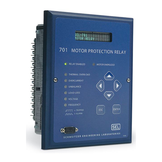
Section 5 Front-Panel Operation Front-Panel Layout The SEL-701 Relay front-panel interface consists of LEDs, a vacuum fluorescent display, a six-button keypad, and an EIA-232 serial port connector. The front-panel layout is shown in Figure 5.1. Relay Enabled LED Vacuum Fluorescent Display... -
Page 122: Normal Front-Panel Display
Figure 5.3. The third is only shown if an RTD failure is detected. SEL-701 MOTOR RELAY Figure 5.3 Default Display Message Screen. Control the contents of these custom messages using the Display Message settings, described in Front-Panel Display Message Settings on page 4.44 in Section 4:... -
Page 123: Front-Panel Automatic Messages
Front-Panel Operation Front-Panel Automatic Messages Front-Panel Automatic Messages The relay displays automatic messages under the conditions described Table 5.1. Table 5.1 Front-Panel Automatic Messages Table 5.1 Front-Panel Automatic Messages Condition Front-Panel Message Shows Motor Running Overloaded Predicted time to thermal element trip, in seconds Section 9: Relay Trip Has Occurred... -
Page 124: Front-Panel Menus & Operations
Front-Panel Menus & Operations Introduction The SEL-701 Relay front panel gives you access to most of the information that the relay measures and stores. You can also use front-panel controls to start or stop the motor, pulse output contacts, and view or modify relay settings. -
Page 125: Table 5.2
Front-Panel Operation Front-Panel Menus & Operations Table 5.2 Front-Panel Pushbutton Functions Table 5.2 Front-Panel Pushbutton Functions Button Function Move up within a menu or data list. While editing a setting value, increases the value of the underlined digit. Move down within a menu or data list. While editing a setting value, decreases the value of the underlined digit. -
Page 126: Figure 5.6 Password Entry Screen
Front-Panel Operation Front-Panel Menus & Operations Before you can perform a front-panel menu activity that is marked with the padlock symbol, you must enter the correct Access Level 2 password once or assert input IN4. After you have correctly entered the password, you can perform other Access Level 2 activities without reentering the password. - Page 127 Front-Panel Operation Front-Panel Menus & Operations Step 4. Using the arrow pushbuttons, continue to move within the character table and select each of the characters to build the Access Level 2 password. Step 5. With the correct Access Level 2 password spelled in the upper line of the display, press the {ESC} pushbutton to move the cursor from the lower line of the display.
-
Page 128: Front-Panel Main Menu
Front-Panel Operation Front-Panel Main Menu Front-Panel Main Menu All access to information and relay settings through the front panel starts at the relay Main Menu. The remainder of this section describes the use of the main and lower level menus. Blank Display Default Meter Display Front-Panel... -
Page 129: Figure 5.9 Main Menu: Start Motor Function
Front-Panel Operation Front-Panel Main Menu Main Menu Item Start Motor Function ENTER Start Motor Start the motor? Yes No To move between Yes and No. Yes: Initiates action; No: Returns to Main Menu. ENTER To select underlined option. Figure 5.9 Main Menu: Start Motor Function. Main Menu Item Emergency Restart Function ENTER... -
Page 130: Figure 5.12 Main Menu: Reset Trip/Targets Function
Front-Panel Operation 5.10 Front-Panel Main Menu Main Menu Item Reset Trip/Targets Function ENTER Reset Trip/Targets Reset Trip Output & Targets? Yes No To move between Yes and No. Yes: Initiates action; No: Returns to Main Menu. ENTER To select underlined option. Figure 5.12 Main Menu: Reset Trip/Targets Function. -
Page 131: Figure 5.14 Set Relay\Relay Elements Function
Front-Panel Operation 5.11 Front-Panel Main Menu Set Relay Menu Item Relay Elements Setting Categories ENTER Relay Elements GENERAL DATA ENTER ↑↓ THERMAL MODEL ELEMENTS OVERCURRENT ELEMENTS Press these keys to move within the list. JOGGING BLOCK ELEMENTS LOAD JAM/LOSS ELEMENTS CURRENT UB ELEMENTS Press this key to ENTER... -
Page 132: Figure 5.15 Set Relay\Ser Setting Categories
Front-Panel Operation 5.12 Front-Panel Main Menu Set Relay Menu Item SER Setting Categories ENTER TRIGGER CONDITIONS ENTER ↑↓ RELAY WORD BIT ALIAS Press these keys to move within the list. Press this key to ENTER select a setting category. Press {ENTER} to select and edit a displayed setting. -
Page 133: Figure 5.16 Set Relay\Front Serial Port Settings
Front-Panel Operation 5.13 Front-Panel Main Menu Set Relay Menu Item Front Serial Port Settings ENTER Front Port Baud rate (300-19200) SPEED=2400 Press these keys to move within the list. Press this key to ENTER select a setting category. Press {ENTER} to select and edit a displayed setting. -
Page 134: Figure 5.17 Set Relay\Rear Serial Port Settings
Front-Panel Operation 5.14 Front-Panel Main Menu Set Relay Menu Item Rear Serial Port Settings ENTER Rear Port Protocol (ASCII, MOD PROTO=ASCII Press these keys to move within the list. Press this key to ENTER edit the displayed setting. Press {ENTER} to select and edit a displayed setting. -
Page 135: Figure 5.19 Set Relay\Time Function
Front-Panel Operation 5.15 Front-Panel Main Menu Set Relay Menu Item Time Function ENTER Time Time= 06:31:02 Edit? Yes No To move between Yes and No. Yes: Initiates action; No: Returns to Set Relay Menu. ENTER To select underlined option. Figure 5.19 Set Relay\Time Function. Set Relay Menu Item Password Function ENTER... -
Page 136: Figure 5.21 Main Menu: Meter Values Function
Front-Panel Operation 5.16 Front-Panel Main Menu Main Menu Item Meter Values Menu ENTER Instantaneous Meter ↑ Meter Values ↓ Thermal & RTD Data Demand Meter Energy Meter Press these keys to move within the list. Max/Min Meter Reset Demands Reset Demand Peaks Press this key to select ENTER an underlined menu item. -
Page 137: Figure 5.23 Meter Values Reset Functions
Front-Panel Operation 5.17 Front-Panel Main Menu Meter Values Menu Item Reset Demand Peaks Function ENTER Reset Demand Peaks Reset Demand Peaks? Yes No To move between Yes and No. Yes: Initiates action; No: Returns to Meter Values Menu. ENTER To select underlined option. Figure 5.23 Meter Values Reset Functions. -
Page 138: Figure 5.26 History Data\Clear History Function
Front-Panel Operation 5.18 Front-Panel Main Menu History Data Menu Item Clear History Function ENTER Clear History Clear History Data? Yes No To move between Yes and No. Yes: Clears History Data Buffer; No: Returns to History Data Menu. ENTER To select underlined option. Figure 5.26 History Data\Clear History Function. -
Page 139: Figure 5.29 Motor Statistics\Average And Peak Data Function
Front-Panel Operation 5.19 Front-Panel Main Menu Motor Statistics Menu Item Average and Peak Data Display ENTER ↑ Avg/Peak Data Starting Time(sec) ↓ Start Current(A) Press these keys to move within the list. Min Start Volts(V) Learned Starting Therm Cap: Figure 5.29 Motor Statistics\Average and Peak Data Function. Motor Statistics Menu Item Trip and Alarm Data Display ENTER... -
Page 140: Figure 5.31 Motor Statistics\Reset Statistics Function
Figure 5.31 Motor Statistics\Reset Statistics Function. Main Menu Item Status of Relay Function ENTER ←→↑↓ Status of Relay Status: OK FID=SEL-701-R100-V0 Offset: IA=OK Offset: IB=OK Press these keys to move within the list of self-test results. TC_START=OK Figure 5.32 Main Menu: Status of Relay Function. -
Page 141: Figure 5.33 Main Menu: View Relay Word Function
Front-Panel Operation 5.21 Front-Panel Main Menu Main Menu Item View Relay Word Function ENTER ↑↓ View Relay Word ↑↓ Press these keys to move within rows of Relay Word. ↑↓ ROW 11 Figure 5.33 Main Menu: View Relay Word Function. Main Menu Item Pulse Output Contact Function ENTER... -
Page 142: Figure 5.36 Main Menu: Reset Thermal Model Function
Front-Panel Operation 5.22 Front-Panel Main Menu Main Menu Item Reset Thermal Model Function ENTER Reset Thermal Model Reset Thermal Model? Yes No To move between Yes and No. Yes: Clears Thermal Model; No: Returns to Main Menu. ENTER To select underlined option. Figure 5.36 Main Menu: Reset Thermal Model Function. -
Page 143: Figure 5.39 Reset Learned Param\Reset Start Therm Cap Function
Front-Panel Operation 5.23 Front-Panel Main Menu Reset Learned Starting Reset Learned Param Menu Item Thermal Capacity Function ENTER Rst Start Therm Cap Reset Learned Start Thermal Cap? Yes No To move between Yes and No. Yes: Resets Learned Start Thermal Cap; No: Returns to Reset Learned Param Menu. - Page 144 This page intentionally left blank...
-
Page 145: Section 6: Ascii Serial Port Operation
ASCII Serial Port Operation Introduction You can interact with the SEL-701 Relay through the front-panel interface or the serial port interface. This section describes the connections and commands used with the serial port interface; the front-panel interface is discussed in Section 5: Front-Panel Operation. -
Page 146: You Will Need
Figure 6.1 on page 6.3. You can use a variety of terminal emulation programs on your personal computer to communicate with the SEL-701 Relay. Examples of PC-based terminal emulation programs include: ProComm Plus™. Relay Gold™. -
Page 147: Connect Your Pc To The Relay
ASCII Serial Port Operation Connect Your PC to the Relay Connect Your PC to the Relay Connect your PC serial port to the SEL-701 Relay serial port using a cable having the pinout shown in Figure 6.1 or a null-modem cable. This and other cables are available from SEL. -
Page 148: Table 6.1
ASCII Serial Port Operation Connect Your PC to the Relay Table 6.1 Pin Functions and Definitions for SEL-701 Relay EIA-232 Serial Ports Pin Functions and Table 6.1 Definitions for SEL-701 Relay EIA-232 Serial Ports Pin Function Definition 1, 4, 6... -
Page 149: Configure Your Terminal Emulation Software
Table 6.2. For the best display, use VT-100 terminal emulation. If VT-100 is not available, WYSE-100 and ANSI terminal emulations also work. Table 6.2 SEL-701 Relay Serial Communication Default Settings Table 6.2 SEL-701 Relay Serial Communication Default Settings Setting Default... -
Page 150: Using Terminal Commands
ASCII Serial Port Operation Using Terminal Commands Using Terminal Commands When you type commands at the terminal emulation screen, you can type in either the entire command or just use the first three letters. For example, the commands EVENT 1 <ENTER> and EVE 1 <ENTER> both cause the relay to display the most recent full length event report. -
Page 151: Serial Port Access Levels
ASCII Serial Port Operation Serial Port Access Levels Serial Port Access Levels The available serial port commands are listed in Table 6.4 on page 6.8. Some commands are not available at Access Level 1 for security reasons. All commands are available at Access Level 2. -
Page 152: Command Summary
Access Level 1 commands are also available in Access Level 2. The commands are shown in upper-case letters, but can also be entered with lower-case letters. Table 6.4 SEL-701 Serial Port Command Summary Table 6.4 SEL-701 Serial Port Command Summary... - Page 153 ASCII Serial Port Operation Command Summary Table 6.4 SEL-701 Serial Port Command Summary (Continued) Access Serial Port Level Command Command Description Page Number Event Analysis Commands EVENT View event reports 6.13 HISTORY View event summaries/histories 6.13 HISTORY R Reset event history data 6.14...
-
Page 154: Command Explanations
ASCII Serial Port Operation 6.10 Command Explanations Command Explanations Each command explanation lists: The command. The serial port access levels where the command is available, in parentheses. An explanation of the command use or response. For example, you can execute the HELP command, below, from serial port Access Level 1 or 2. -
Page 155: Figure 6.4 2Ac Command Example
If you make three incorrect password guesses, access is denied and the ALARM contact closes for one second. Figure 6.4 shows an example 2AC command execution. =>2AC Password: ? 701@@@ SEL-701 Date: 08/27/1999 Time: 11:01:59.467 MOTOR RELAY Level 2 =>> Figure 6.4 2AC Command Example. -
Page 156: Table
(1–4). The relay repeats your command followed by a colon. At the colon, type the Control subcommand you wish to perform (see Table 6.5). Table 6.5 SEL-701 Relay Control Subcommands Table 6.5 SEL-701 Relay Control Subcommands Subcommand Description SRB n Set Remote Bit n (“ON”... -
Page 157: Table 6.6
ASCII Serial Port Operation 6.13 Command Explanations =>>DATE 09/01/99 09/01/1999 =>> Figure 6.6 DATE Command Example. EVENT (Level 1 or 2) Use the EVENT command to view event reports. The general command format is listed in Table 6.6. Table 6.6 Event Commands Table 6.6 Event Commands... -
Page 158: Table 6.8
ASCII Serial Port Operation 6.14 Command Explanations =>HIS 1 SEL-701 Date: 07/07/1999 Time: 15:51:24.365 MOTOR RELAY Event: UNBALANCED CURRENT Event #: 1 Event Date: 07/07/1999 Event Time: 14:39:47.907 Frequency (Hz): 60.00 % Thermal Capacity: 69.0 % Unbalance Current: 15.3 Currents (A): 259.7... - Page 159 ASCII Serial Port Operation 6.15 Command Explanations The date entries used with the LDP command should match the Date Format setting. If the Date Format setting equals MDY, then the dates entered should have the format mm/dd/yyyy. If the Date Format setting equals YMD, then the dates entered should have the format yyyy/mm/dd.
-
Page 160: Figure 6.8 Meter Command Example
ASCII Serial Port Operation 6.16 Command Explanations =>METER SEL-701 Date: 08/01/1999 Time: 15:59:15.739 MOTOR RELAY I MAG (A, Fn) 69.74 69.85 69.61 0.00 0.33 (A,RMS) 69.66 69.77 69.62 0.02 I ANG (DEG) -45.08 -164.96 75.02 -156.51 -130.61 V MAG (V, Fn) -
Page 161: Figure 6.10 Meter E Command Example
ASCII Serial Port Operation 6.17 Command Explanations =>METER E SEL-701 Date: 08/01/1999 Time: 15:59:41.738 MOTOR RELAY MWhr MVARhr-IN MVARhr-OUT MVAhr LAST RESET 07/02/1999 11:10:05.370 => Figure 6.10 METER E Command Example. Maximum/Minimum Metering: METER M The METER M command displays the maximum and minimum values of assorted current, voltage, power, and temperature quantities. -
Page 162: Figure 6.12 Meter T Command Example
If the motor is not in overload, the time shown is 9999 seconds. The number of starts this hour and the minutes since the last start are also shown. =>METER T SEL-701 Date: 09/01/1999 Time: 16:00:07.876 MOTOR RELAY... -
Page 163: Table 6.9
ASCII Serial Port Operation 6.19 Command Explanations Average and peak starting times, starting current magnitudes, thermal capacities, and other average and peak operating values. Learned motor cooling time (if RTDs are included) and learned starting thermal capacity. Trip and alarm counters, listed by type. Section 8: Metering &... -
Page 164: Table 6.10 Pulse Command Format
ASCII Serial Port Operation 6.20 Command Explanations PASSWORD (Level 2) PAS allows you to inspect or change the existing password. To inspect the Access Level 2 password, type: PAS <ENTER>. The relay will display the present password. The factory default password is 701. To change the password for Access Level 2 to BIKE, enter: PAS 2 BIKE <ENTER>. -
Page 165: Figure 6.13 Pulse Command Example
ASCII Serial Port Operation 6.21 Command Explanations =>>PUL TRIP 1 Are you sure (Y/N) ? Y =>> Figure 6.13 PULSE Command Example. QUIT (Level 2) The QUI command returns the relay to Access Level 1. RLP (Level 2) Use the RLP (Reset Learned Parameters) command at Access Level 2 to reset the learned motor parameters. -
Page 166: Table 6.11 Ser Command Options
ASCII Serial Port Operation 6.22 Command Explanations Table 6.11 SER Command Options Table 6.11 SER Command Options Serial Port Command Description Display all available SER records. SER n Display the n most recent SER records, starting with record n. SER n1 n2 Display SER records n2 to n1, starting with n2. -
Page 167: Table 6.13 Set Command Editing Keystrokes
ASCII Serial Port Operation 6.23 Command Explanations Table 6.13 SET Command Editing Keystrokes Table 6.13 SET Command Editing Keystrokes Press Key(s) Results <ENTER> Retains setting and moves to the next setting. ^ <ENTER> Returns to previous setting. < <ENTER> Returns to previous setting category. >... -
Page 168: Table 6.15 Show Command Options
ASCII Serial Port Operation 6.24 Command Explanations SHOW (Level 1 or 2) Use the SHOW command to view relay settings, serial port settings, and SER settings. SHOW command options are listed in Table 6.15. Table 6.15 SHOW Command Options Table 6.15 SHOW Command Options Command Description... -
Page 169: Figure 6.15 Show Command Example
ASCII Serial Port Operation 6.25 Command Explanations =>SHOW Relay Settings: =SEL-701 =MOTOR RELAY = 20 ITAP CTRN = 10 INTAP PHROT = ABC FNOM = 60 DATE_F = MDY DMTC = 15 DELTA_Y = Y SINGLEV = N SETMETH = RATING = 5.00... -
Page 170: Table 6.16 Status Command Options
ASCII Serial Port Operation 6.26 Command Explanations STATUS (Level 1 or 2) The STATUS command displays the relay self-test information. To view a status report, enter the command STATUS. To view the status report k times, enter the command STATUS k, where k is a number between 1 and 32767. STATUS Command Row &... -
Page 171: Figure 6.16 Status Command Example
ASCII Serial Port Operation 6.27 Command Explanations =>STATUS SEL-701 Date: 09/01/1999 Time: 16:01:28.364 MOTOR RELAY FID=SEL-701-R102-V11xxx-Z000000-D19990730 CID=D5EE SELF TESTS Offset: Offset: +5V_PS -5V_PS +15V_PS +28V_PS TEMP CR_RAM EEPROM BATTERY LC_TIME TC_START Relay Enabled => Figure 6.16 STATUS Command Example. STATUS R (Level 2) To reset the self-test status and restart the relay, use the STA R command from Access Level 2. -
Page 172: Figure 6.17 Target Command Example
ASCII Serial Port Operation 6.28 Command Explanations A Relay Word bit is either at a logical 1 (asserted) or a logical 0 (deasserted). =>TARGET 1 STARTING RUNNING STOPPED JAMTRIP LOSSALRM LOSSTRIP 46UBA 46UBT => Figure 6.17 TARGET Command Example. The TAR command options are listed in Table 6.17. - Page 173 ASCII Serial Port Operation 6.29 Command Explanations 701 Motor Protection Relay Date Code 20010719...
-
Page 174: Figure 6.18 Time Command Example
ASCII Serial Port Operation 6.30 Command Explanations Table 6.19 SEL-701 Relay Word & Corresponding TAR Command Table 6.19 SEL-701 Relay Word & Corresponding TAR Command Relay Word Bits STARTING RUNNING STOPPED JAMTRIP LOSSALRM LOSSTRIP 46UBA 46UBT THERMLO NOSLO TBSLO ABSLO... -
Page 175: Figure 6.19 Trigger Command Example
ASCII Serial Port Operation 6.31 Command Explanations TRIGGER (Level 1 or 2) Use the TRIGGER command to generate an event report. See Section 9: Event Analysis for more information on event reports. =>TRIGGER Triggered => Figure 6.19 TRIGGER Command Example. 701 Motor Protection Relay Date Code 20010719... -
Page 176: Serial Port Automatic Messages
ASCII Serial Port Operation 6.32 Serial Port Automatic Messages Serial Port Automatic Messages When the serial port AUTO setting is Y, the relay sends automatic messages to indicate specific conditions. The automatic messages are described in Table 6.20. Table 6.20 Serial Port Automatic Messages Table 6.20 Serial Port Automatic Messages... -
Page 177: Section 7: Commissioning
Section 7 Commissioning Introduction This section provides guidelines for commissioning and testing the SEL-701 Relay. SEL performs a complete functional check and calibration of each relay before it is shipped. This helps to ensure that you receive a relay that operates correctly and accurately. -
Page 178: Relay Commissioning Procedure
Relay Commissioning Procedure Relay Commissioning Procedure Introduction This procedure is a guideline to help you enter settings into the SEL-701 Relay and verify that it is properly connected. Modify the procedure as necessary to conform with your standard practices. Use the commissioning procedure at initial relay installation; you should not need to repeat it unless major changes are made to the relay electrical connections. - Page 179 Settings Sheets for your application. If you are using the SEL-701PC software, you can use it to develop, store, and transfer settings to the SEL-701 Relay. Section 3: SEL-701PC Software for more details on the SEL-701PC software.
-
Page 180: Figure 7.1 Three-Phase Ac Connection Test Signals
Commissioning Relay Commissioning Procedure current correctly, taking into account the relay PTR and CTR settings and the fact that the quantities are displayed in primary units. This step verifies the signal polarity and per-phase ac connections to the relay. Apply rated ac current (1 A or 5 A) to the relay IN input if used. Use the front-panel or serial port METER function to verify that the relay is measuring current magnitude and phase angle correctly, taking into account the relay CTRN setting and the... -
Page 181: Figure 7.2 Open-Delta Ac Potential Connection Test Signals
Commissioning Relay Commissioning Procedure 60° 60° PHROT = ACB PHROT = ABC When setting PHROT = ABC, set angle Ia = 0° When setting PHROT = ACB, set angle Ia = 0° set angle Ib = -120° set angle Ib = 120°... -
Page 182: Table 7.1
Commissioning Relay Commissioning Procedure NOTE: The MOT R, MST R, and SER R commands should only be used at initial installation. Do not reset the motor operating statistics or SER buffer following routine maintenance unless you are very familiar with the use of the data contained in these buffers and are certain that the data is no longer needed. - Page 183 PHROT. A nonzero 3V0 meter value, if shown, typically indicates a single- phase voltage connection problem. Step 18. The SEL-701 Relay is now ready for continuous service. 701 Motor Protection Relay Date Code 20010719...
-
Page 184: Selected Functional Tests
Commissioning Selected Functional Tests Selected Functional Tests Test Connections Refer to Table 7.2 to determine which test source connection diagram to use for testing in your application. Table 7.2 Test Source Connections for Different Relay Configurations Table 7.2 Test Source Connections for Different Relay Configurations AC Configuration Test Source Connections Figure 7.3... - Page 185 Commissioning Selected Functional Tests 701 Motor Protection Relay Date Code 20010719...
- Page 186 Commissioning 7.10 Selected Functional Tests 701 Motor Protection Relay Date Code 20010719...
-
Page 187: Table 7.3
Commissioning 7.11 Selected Functional Tests Phase Current Measuring Accuracy Step 1. Connect the current sources to the IA, IB, and IC current inputs (5 A or 1 A, as indicated by the ITAP setting). Step 2. Using the front-panel Set Relay\Relay Elements\General Data functions or serial port SHOW command, note the CTR and PHROT settings. -
Page 188: Table 7.4
Commissioning 7.12 Selected Functional Tests Neutral Current Measuring Accuracy Step 1. Connect one current source to the IN current input (5 A or 1 A, as indicated by the INTAP setting) to test neutral current measuring accuracy. Step 2. Using the front-panel Set Relay\Relay Elements\General Data functions or serial port SHOW command, note the CTRN setting. -
Page 189: Table 7.5
Commissioning 7.13 Selected Functional Tests Step 3. Set the current source phase angles to apply balanced three-phase currents. Refer to Figure 7.1 on page 7.4 for the correct angles that depend on the PHROT setting. Step 4. Turn on the current sources and increase the current applied to the relay. -
Page 190: Table 7.6
Commissioning 7.14 Selected Functional Tests NOTE: Changing settings requires that you enter the Access Level 2 password. The factory password is 701. Step 3. Set the current source phase angles to apply balanced three-phase currents. Refer to Figure 7.1 on page 7.4 for the correct angles, which depend on the PHROT setting. -
Page 191: Table 7.7
Commissioning 7.15 Selected Functional Tests Analog Output Accuracy Step 1. Connect a dc milliammeter in series with the analog output terminals (B01, B02). Connect a PC to the relay front-panel serial port using an appropriate serial cable. Using the SEL-701PC software terminal function or other terminal emulation software, establish communications with the relay at Access Level 2 (see Section 6:... -
Page 192: Table 7.8
Commissioning 7.16 Selected Functional Tests Table 7.8 100-Ohm Platinum RTD Type (RTDs 1–6) Table 7.8 100-Ohm Platinum RTD Type (RTDs 1–6) Expected Expected Resistance Temperature Temperature Value Reading Reading RTD Temperatures (ohms) (°C) (°F) 80.31 –50 –58 100.00 119.39 138.50 157.32 175.84 190.45... -
Page 193: Table 7.10 120-Ohm Nickel Rtd Type (Rtds 1–6)
Commissioning 7.17 Selected Functional Tests Table 7.10 120-Ohm Nickel RTD Type (RTDs 1–6) Table 7.10 120-Ohm Nickel RTD Type (RTDs 1–6) Expected Expected Resistance Temperature Temperature Value Reading Reading RTD Temperatures (ohms) (°C) (°F) 86.17 –50 –58 120.00 157.74 200.64 248.95 303.64 353.14... -
Page 194: Table 7.12 100-Ohm Nickel Rtd Type (Rtds 1–6)
Commissioning 7.18 Selected Functional Tests Table 7.12 100-Ohm Nickel RTD Type (RTDs 1–6) Table 7.12 100-Ohm Nickel RTD Type (RTDs 1–6) Expected Expected Resistance Temperature Temperature Value Reading Reading RTD Temperatures (ohms) (°C) (°F) 71.81 –50 –58 100.00 131.45 167.20 207.45 252.88 294.28... -
Page 195: Table 7.14 10-Ohm Copper Rtd Type (Rtds 1–6)
Commissioning 7.19 Selected Functional Tests Table 7.14 10-Ohm Copper RTD Type (RTDs 1–6) Table 7.14 10-Ohm Copper RTD Type (RTDs 1–6) Expected Expected Resistance Temperature Temperature Value Reading Reading RTD Temperatures (ohms) (°C) (°F) 7.10 –50 –58 9.04 10.97 12.90 14.83 16.78 18.34... -
Page 196: Table 7.16 Power Measuring Accuracy Test Values, Wye Voltages
Commissioning 7.20 Selected Functional Tests Step 2. Using the front-panel Set Relay\Relay Elements\General Data function or serial port SHOW command, note the CTR, PTR, and PHROT settings. Step 3. Referring to Table 7.16, set the current and voltage source magnitudes. The phase angles you should apply depend on the PHROT setting. -
Page 197: Table 7.17 Power Measuring Accuracy Test Values, Delta Voltages
Commissioning 7.21 Selected Functional Tests Table 7.17 Power Measuring Accuracy Test Values, Delta Voltages Table 7.17 Power Measuring Accuracy Test Values, Delta Voltages Applied Currents Reactive and Voltages Real Power Power Power Factor (kW) (kVar) (pf) Expected: Expected: Expected: PHROT = ABC P = 0.4677 •... - Page 198 This page intentionally left blank...
-
Page 199: Section 8: Metering & Monitoring
Section 8 Metering & Monitoring Introduction The SEL-701 Relay features metering functions to display the present values of current and (if included) voltage and RTD measurements. The relay provides several methods to read the present meter values, including: Rotating front-panel display. -
Page 200: Table 8.1
Metering & Monitoring Introduction Details on each of the meter data types are shown below. Section 5: Front-Panel Operation Section 6: ASCII Serial Port Operation describe how to access the various types of meter data using the relay front panel and serial ports. Instantaneous Metering Table 8.1 Measured Values... -
Page 201: Table 8.2
Metering & Monitoring Introduction Demand Metering Table 8.2 Demand Meter Values Table 8.2 Demand Meter Values Relay Option Demand Meter Values All Models Ia, Ib, Ic, In Fundamental Demand Magnitudes Ig Residual Current Fundamental Demand Magnitude Negative-Sequence Current (3I2) Fundamental Demand Magnitude With Voltage kW, kVAR, kVA Fundamental Demand Magnitudes Inputs (Relay... -
Page 202: Table 8.4
Metering & Monitoring Introduction The relay records maximum and minimum instantaneous quantities while the following conditions are true: The motor is running. Phase currents are greater than 3% of the Phase CT Secondary Rating, ITAP setting. Phase voltages, if included, are greater than 13 Vac. Residual voltage is recorded only if three phase-neutral voltages are connected to the relay and residual voltage is greater than 3 Vac. -
Page 203: Table 8.5
Metering & Monitoring Introduction Table 8.5 RTD Input Status Messages Table 8.5 RTD Input Status Messages Message Status Open RTD leads open Short RTD leads shorted Comm. Fail Fiber-optic communications to SEL-2600 RTD Module have failed Stat Fail SEL-2600 RTD Module self-test status failure Energy Metering Table 8.6 Energy Meter Values... -
Page 204: Power Measurement Conventions
S3 = VI S4 = VI P– S2 = VI S1 = VI Q– Figure 8.1 Power Measurement Conventions. In the SEL-701 Relay, reported positive real power and energy are always into the motor. 701 Motor Protection Relay Date Code 20010719... -
Page 205: Load Profiling
Metering & Monitoring Load Profiling Load Profiling The SEL-701 Relay includes a built-in load profiling function that does not require any configuration. The relay automatically records selected quantities into nonvolatile memory every 15 minutes, synchronized to the quarter-hour. The relay... -
Page 206: Figure 8.2 Ldp Command Response
Metering & Monitoring Load Profiling =>ldp SEL-701 Date: 08/26/1999 Time: 16:32:38.364 MOTOR RELAY Record Number,Date,Time,Ia,Ib,Ic,In,% Thermal Capacity,% Current Unbalance,Frequ ency,Winding RTD,Bearing RTD,Ambient RTD,Vab,Vbc,Vca,kW,kVAR,kVA 3,08/26/1999,16:00:00,190,192,191,0,69,0,60.0,150,112,78,458,460,457,156,44,162 2,08/26/1999,16:15:00,192,194,190,0,70,0,60.0,151,112,79,460,464,460,156,44,161 1,08/26/1999,16:30:00,190,190,192,0,69,0,60.0,150,111,78,458,462,463,156,44,162 => Figure 8.2 LDP Command Response. 701 Motor Protection Relay Date Code 20010719... -
Page 207: Motor Operating Statistics
Motor Operating Statistics Motor Operating Statistics The SEL-701 Relay retains useful information regarding the protected motor. The serial port MOTOR command and front-panel Motor Statistics commands make the stored data available. The data also appear in the Modbus memory map. Items included in the report are shown below. - Page 208 Motor Operating Statistics Learned Parameters The SEL-701 Relay can learn two protection parameters of the protected motor. When you connect the relay to monitor at least one motor winding RTD and the ambient temperature, the relay can learn the cooling time of the protected motor when it is stopped.
-
Page 209: Figure 8.3 Motor Command Example
Metering & Monitoring 8.11 Motor Operating Statistics =>MOTOR SEL-701 Date: 09/01/1999 Time: 16:00:14.625 MOTOR RELAY Operating History, elapsed time in ddd:hh:mm Since: 07/02/1999 10:56:15 Running time: > 0:01:58 Stopped time: 54:23:47 Time running: 0.1% Total MWhr: Number of starts: Average... -
Page 210: Motor Start Report
Metering & Monitoring 8.12 Motor Start Report Motor Start Report Each time the relay detects a motor start, it stores a motor start report. The five latest motor start reports are stored in nonvolatile memory. View any of the five latest motor start reports using the serial port MSR n command, where n = 1–5. -
Page 211: Figure 8.4 Motor Start Report Example
8.13 Motor Start Report Executing the MSR F command does not affect the statistical data stored by the relay. Figure 8.4 shows data from an example Motor Start Report. =>msr SEL-701 Date: 07/21/1999 Time: 17:13:04.295 MOTOR RELAY FID=SEL-701-R102-V11xxx-Z000000-D19990702 CID=DE83 Date of Motor Start:... -
Page 212: Motor Start Trending
If relay power is removed, the information collected between midnight and power removal is lost. Figure 8.5 shows data from an example Motor Start Trend Report. =>mst SEL-701 Date: 08/27/1999 Time: 10:35:49.755 MOTOR RELAY Began Number... -
Page 213: Section 9: Event Analysis
Event Analysis Introduction The SEL-701 Relay provides several facilities to analyze the cause of relay operations. Use these tools to help diagnose the cause of the relay operation and more quickly restore the protected motor to service. Each tool, listed below, provides increasing detail regarding the causes of a relay operation. -
Page 214: Front-Panel Target Leds
Event Analysis Front-Panel Target LEDs Front-Panel Target LEDs Table 9.1 SEL-701 Relay Front-Panel Target LED Definitions Table 9.1 SEL-701 Relay Front-Panel Target LED Definitions LED Label Definition Relay Enabled Illuminated whenever the relay is in service. If this LED is not illuminated, the relay is out of service. - Page 215 Event Analysis Front-Panel Target LEDs Resetting Front-Panel Targets To reset the front-panel tripping targets, select the Reset Trip/Targets function from the front-panel display main menu, or execute the serial port TARGET R command. When you reset the relay targets using one of these methods: All tripping LEDs are extinguished if the trip condition has vanished and no lockout conditions remain.
-
Page 216: Front-Panel Messages
Event Analysis Front-Panel Messages Front-Panel Messages Each time the relay trips in response to a fault, it automatically displays a front-panel message. The message describes the type of trip that occurred. Trip messages include: Thermal Trip. Locked Rotor Trip. Load-Loss Trip. Load-Jam Trip. -
Page 217: History Data & Event Summaries
History Data & Event Summaries History Data & Event Summaries Each time the SEL-701 Relay trips, and in response to other selected conditions, the relay captures motor current, voltage (if included), RTD (if included), protection element, contact input, and contact output information. This collection of data is called... - Page 218 Event Analysis History Data & Event Summaries Event Trigger Event Type TRIGGER Command TRIG PULSE Command PULSE RISING EDGE of ER SEL control equation OGIC STOP Command STOP COMMAND If the event was stored in response to a rising edge of the TRIP SEL control OGIC equation, but the trip type doesn’t correspond to any of the trip messages in...
-
Page 219: Event Reports
Event Analysis Event Reports Event Reports The SEL-701 Relay captures and stores detailed information concerning the relay measurements, protection element status, and contact input/output status. The relay stores the 14 most recent event reports in nonvolatile memory. Each report is numbered;... -
Page 220: Table 9.2
Display most recent report at -cycle resolution; analog data are not digitally filtered (raw). The SEL-701 Relay also provides a facility to allow you to download event report â data using Modbus protocol and the rear-panel serial port. For more information, see Appendix C: Modbus®... -
Page 221: Table 9.4
Event Analysis Event Reports software uses to display oscillographic information include data for 16 samples per power system cycle. In event reports, time runs down the page; first occurrences are shown at the top of the page, final conditions at the bottom. Events contain 4 cycles of pretrigger data and 11 cycles of posttrigger data to show the motor and system conditions before, during, and after the fault. -
Page 222: Table 9.5
Event Analysis 9.10 Event Reports Table 9.5 Output, Input, and Element Event Report Columns Output, Input, and Table 9.5 Element Event Report Columns Column Heading Symbol Definition All columns • Element/input/output not picked up or not asserted. Motor Motor starting. Motor running. -
Page 223: Table 9.5
Event Analysis 9.11 Event Reports Output, Input, and Element Table 9.5 Event Report Columns (Continued) Column Heading Symbol Definition A Winding RTD has exceeded the alarm temperature. One or two Winding RTDs have exceeded the trip temperature. A Bearing RTD has exceeded the alarm temperature. One or two Bearing RTDs have exceeded the trip temperature. - Page 224 Event Reports Filtered & Unfiltered Event Reports The SEL-701 Relay samples the basic power system measurands (ac current and ac voltage) 16 times per power system cycle. The relay filters the measurands to remove transient signals. Four times per cycle the relay operates on the filtered values and reports them in the event report.
-
Page 225: Sequential Events Recorder (Ser) Report
SER Trigger Condition Aliases You may rename any of the SER trigger conditions using the SEL-701 Relay ALIAS settings. The relay permits up to 20 aliases to be assigned to conditions that trigger SER row entries. For instance, the factory default logic settings define contact input IN5 for operation as an Emergency Restart input. - Page 226 Event Analysis 9.14 Sequential Events Recorder (SER) Report Table 9.6 Retrieving SER Reports (Continued) Example SER Serial Port Commands Format If you enter the SER command with a single number SER 17 following it, the relay displays that number of rows, if they exist.
- Page 227 Event Analysis 9.15 Sequential Events Recorder (SER) Report The date entries in the previous example SER commands depend on the Date Format setting DATE_F. If setting DATE_F is equal to MDY, you should enter the dates as in the above examples (Month/Day/Year). If setting DATE_F is equal to YMD, you should enter the dates Year/Month/Day.
-
Page 228: Example Event Report
The asterisk (*) in the column following the Vc column identifies the row where the event summary data was taken. If the “trigger” row (>) and the summary row (*) are the same, the * symbol takes precedence. SEL-701 Date: 07/07/1999 Time: 14:39:47.907 Event Date &... -
Page 229: Figure 9.1 Example Event Report
Bearing Ambient Other samples of 4th cycle Hottest RTD(F): Voltages (V): kVAR Power: 163.8 44.1 169.6 0.97 LAG Relay Settings: =SEL-701 =MOTOR RELAY = 60 ITAP CTRN = 60 INTAP PHROT = ABC FNOM = 60 DATE_F = MDY DMTC... -
Page 230: Example Sequential Events Recorder (Ser) Report
Example Sequential Events Recorder (SER) Report Example Sequential Events Recorder (SER) Report This example SER report (Figure 9.2) corresponds to the event report in Figure 9.1. SEL-701 Date: 07/07/1999 Time: 14:50:04.744 MOTOR RELAY FID=SEL-701-R100-V11Xxx-Z000000-D199907071 CID=1905 DATE TIME ELEMENT STATE 06/07/1999 14:34:32.786 MOTOR_STOPPED ENDS 06/07/1999 14:34:32.786... -
Page 231: Table 9.7 Example Sequential Events Recorder (Ser) Report Explanations
Event Analysis 9.19 Example Sequential Events Recorder (SER) Report Table 9.7 Example Sequential Events Recorder (SER) Report Explanations Example Sequential Events Table 9.7 Recorder (SER) Event Report Explanations Item # Explanation 13, 12, 11, 10, 9, 8 After a 10-second accelerating time, the motor relay indicates the motor is running (11). - Page 232 This page intentionally left blank...
-
Page 233: Section 10: Maintenance & Troubleshooting
This review frequently reveals problems with equipment external to the relay such as voltage transformers and control wiring. The SEL-701 Relay does not require specific routine tests, but your operational standards may require some periodic relay verification. If you need or wish to perform periodic relay verification, we recommend the following checks. -
Page 234: Table 10.1 Data Capture
Maintenance & Troubleshooting 10.2 Routine Maintenance Checks Contact Output Verification Use the front-panel Pulse Out Contact\Trip command to close the TRIP output contact. Repeat for the other output contacts. Make sure that each contact operates properly in its designated annunciation, control, or tripping circuit. See Section 5: Front-Panel Operation Section 6: ASCII Serial Port Operation... -
Page 235: Self-Testing
Maintenance & Troubleshooting 10.3 Self-Testing Self-Testing The relay runs a variety of self-tests. As shown below, when the relay detects certain types of self-test failures, it closes the ALARM output b-contact. Monitoring this contact is the single most important relay maintenance activity that you can perform. - Page 236 Maintenance & Troubleshooting 10.4 Self-Testing Table 10.2 Relay Self-Tests (Continued) Protection ALARM Front-Panel Disabled Output Message Self-Test Description Limits on Failure on Failure on Failure –5 V PS Measures the –4.65 V Latched –5V FAILURE –5 V power –5.40 V supply.
- Page 237 Maintenance & Troubleshooting 10.5 Self-Testing Table 10.2 Relay Self-Tests (Continued) Protection ALARM Front-Panel Disabled Output Message Self-Test Description Limits on Failure on Failure on Failure Micro- Monitors the Latched CLOCK processor microprocessor STOPPED Crystal crystal. Micro- The micro- Test fails Latched VECTOR nn processor...
-
Page 238: Troubleshooting Procedure
Maintenance & Troubleshooting 10.6 Troubleshooting Procedure Troubleshooting Procedure Relay Enabled Front-Panel LED Dark Table 10.3 Relay Enabled Front-Panel LED Dark Table 10.3 Relay Enabled Front-Panel LED Dark Possible Cause Solution Verify input power and fuse continuity. Input power not present or fuse is blown. -
Page 239: Table 10.6 Relay Does Not Respond To Command From Device Connected To Serial Port
Maintenance & Troubleshooting 10.7 Troubleshooting Procedure Relay Does Not Respond to Commands From Device Connected to Serial Port Table 10.6 Relay Does Not Respond to Command from Device Connected to Serial Port Relay Does Not Respond Table 10.6 to Commands From Device Connected to Serial Port Possible Cause Solution Communications device not... -
Page 240: Power Supply Fuse Replacement
Maintenance & Troubleshooting 10.8 Power Supply Fuse Replacement Power Supply Fuse Replacement The relay power supply is equipped with a fuse that you can replace without disassembling the relay. The fuse holder is located on the relay rear panel, immediately above the power supply input terminals, D01–D03. -
Page 241: Real-Time Clock Battery Replacement
Maintenance & Troubleshooting 10.9 Real-Time Clock Battery Replacement Real-Time Clock Battery Replacement A lithium battery powers the relay clock (date and time) if the external power source is lost or removed. The battery is a 3 V lithium coin cell, Rayovac No. BR2335 or equivalent. -
Page 242: Firmware Upgrade Installation
Firmware Upgrade Installation SEL occasionally offers firmware upgrades to improve the performance of your relay. Since the SEL-701 Relay stores firmware in flash memory, changing physical components is not necessary. Upgrade the relay firmware by downloading a file from a personal computer to the relay via the front-panel serial port as outlined in the following sections. - Page 243 Maintenance & Troubleshooting 10.11 Firmware Upgrade Installation Step 6. Type BAU 38400 <ENTER>. This will change the baud rate of the communications port to 38400. Change the baud rate of your PC to 38400 to match the relay. Step 7. Make a copy of the firmware currently in the relay.
- Page 244 SEL-701 Relay, re-auto-configure the SEL-20x0 port. This step will prevent a future auto-configuration failure of the SEL-20x0 when its power is cycled and the new SEL-701 Relay firmware does not match the original configuration. The relay is now ready for your commissioning procedure.
-
Page 245: Factory Assistance
10.13 Factory Assistance Factory Assistance The employee-owners of Schweitzer Engineering Laboratories, Inc. are dedicated to making electric power safer, more reliable, and more economical. We appreciate your interest in SEL products, and we are committed to making sure you are satisfied. If you have any questions, please contact us at: Schweitzer Engineering Laboratories, Inc. - Page 246 This page intentionally left blank...
-
Page 247: Appendix A Firmware Versions
Appendix A Firmware Versions This manual covers SEL-701 Relays that contain firmware bearing the most recent part numbers and revision numbers listed at the top of Table A.1 (most recent firmware listed at top): Table A.1 SEL-701 Relay Firmware Versions Table A.1... - Page 248 Firmware Versions Table A.1 SEL-701 Relay Firmware Versions (Continued) Firmware Part/Revision No. Description of Firmware Base Version Modified front-panel password FID: SEL-701-R102-Vx0xxx-Z000000-D19990730 entry function. Added MSR F command Voltage Option support. FID: SEL-701-R102-Vx1xxx-Z000000-D19990730 Added “Began on Date” to MST command response.
-
Page 249: Introduction
Control Equations & Relay Logic Introduction The SEL-701 Relay is equipped with programmable logic so you can customize various relay functions. Use the programmable logic components described in this appendix to modify the factory default logic settings discussed in Section 4: Settings OGIC ®... -
Page 250: Relay Functional Overview
Data Acquisition & Filtering The SEL-701 Relay passes ac current and (if included) voltage signals through low-pass filters to remove signals above the eighth harmonic. Then the relay digitally samples the signals 16 times per power system cycle. The relay automatically tracks system frequency over the range of 20 to 70 Hz to ensure that exactly 16 samples are taken every cycle. - Page 251 OGIC ® Control Equations & Relay Logic Relay Functional Overview 701 Motor Protection Relay Date Code 20010719...
-
Page 252: Relay Word Bits
TAR command (see TARGET (Level 1 or 2) on page 6.27 in Section 6: ASCII Serial Port Operation). Table B.1 SEL-701 Relay Word Bits Table B.1 SEL-701 Relay Word Bits Relay Word Bits STARTING... -
Page 253: Table B.2 Relay Word Bit Definitions For Sel-701
OGIC ® Control Equations & Relay Logic Relay Word Bits Table B.2 Relay Word Bit Definitions for SEL-701 Table B.2 Relay Word Bit Definitions for SEL-701 Definition STARTING Asserts when protected motor is starting (current is greater than 2.5 times motor rated full load current). - Page 254 OGIC ® Control Equations & Relay Logic Relay Word Bits Table B.2 Relay Word Bit Definitions for SEL-701 (Continued) Definition Phase Reversal Trip. Asserts when the relay detects a phase reversal condition, if phase reversal tripping is enabled by the relay settings.
- Page 255 OGIC ® Control Equations & Relay Logic Relay Word Bits Table B.2 Relay Word Bit Definitions for SEL-701 (Continued) Definition AMBALRM Ambient Temperature Alarm and Trip. AMBALRM asserts if the healthy ambient RTD temperature exceeds its alarm AMBTRIP setpoint. AMBTRIP asserts when the healthy ambient RTD temperature exceeds its trip setpoint.
- Page 256 OGIC ® Control Equations & Relay Logic Relay Word Bits Table B.2 Relay Word Bit Definitions for SEL-701 (Continued) Definition control equation variables 1 through 4. OGIC SV1T control equation variable 1 through 4 with settable OGIC pickup and dropout time delay.
-
Page 257: Sel Ogic Control Equations
OGIC ® Control Equations & Relay Logic Control Equations OGIC Control Equations OGIC control equations combine relay protection and control elements with OGIC logic operators to create custom protection and control schemes. This section shows how to set the protection and control elements (Relay Word bits) in the SEL OGIC control equations. -
Page 258: Figure B.2 Result Of Falling-Edge Operator On A Deasserting Underfrequency Element
OGIC ® Control Equations & Relay Logic B.10 Control Equations OGIC With this setting, SV1 is true, or logical 1, when both 50P1T and IN4 are true. Any number of Relay Word bits may be ANDed together within an equation, subject to the overall limitations described in Control Equation Limitations on page B.12. - Page 259 OGIC ® Control Equations & Relay Logic B.11 Control Equations OGIC Control Equation Rising-Edge Operator [/] OGIC Use the rising-edge operator [/] with individual Relay Word bits to cause a single processing-cycle assertion when the Relay Word bit changes state from logical 0 to logical 1.
- Page 260 OGIC ® Control Equations & Relay Logic B.12 Control Equations OGIC Control Equation Limitations OGIC Each single SEL control equation setting is limited to 25 Relay Word bits OGIC that you can combine together with the SEL control equation operators listed in OGIC Table B.3 on page B.9.
-
Page 261: Factory Default Logic Settings
OGIC ® Control Equations & Relay Logic B.13 Factory Default Logic Settings Factory Default Logic Settings When you use the factory default logic by setting FACTLOG equal to Y, the relay hides the logic settings and default settings shown below. Operation of these default settings is described in Section 4: Settings Calculation. - Page 262 OGIC ® Control Equations & Relay Logic B.14 Factory Default Logic Settings Continued from previous page OUTPUT LOGIC TRIP =JAMTRIP + 46UBT + 49T + 50P1T + 50P2T + 50N1T + 50N2T + 50G1T + 50G2T + 50QT + 47T + SPDSTR + WDGTRIP + BRGTRIP + AMBTRIP + OTHTRIP + 81D1T + 81D2T + 81D3T + !27P1 * (LOSSTRIP + 37PT + 55T + VART) + IN2 ULTRIP =0...
-
Page 263: Front-Panel Display Message Configuration
Control Equations & Relay Logic B.15 Front-Panel Display Message Configuration Front-Panel Display Message Configuration There are four text display messages available in the SEL-701 Relay. Each text display has two complementary screens. control equation display message setting DMn (n = 1–6) controls the OGIC display of corresponding, complementary text settings. -
Page 264: Nondedicated Sel Ogic Control Equation Variable Settings
Nondedicated SEL Control Equation Variable Settings OGIC Nondedicated SEL OGIC Control Equation Variable Settings The SEL-701 Relay is equipped with four nondedicated SEL control OGIC equation variables. Each variable has a defining SEL control equation, a OGIC time-delay pickup timer, and a time-delay dropout timer. -
Page 265: Latch Control Switch Settings
B.17 Latch Control Switch Settings Latch Control Switch Settings The latch control switch feature of the SEL-701 Relay replaces latching relays. The state of a traditional latching relay output contact is changed by pulsing the latching relay inputs. (See Figure B.4). - Page 266 OGIC ® Control Equations & Relay Logic B.18 Latch Control Switch Settings Latch Control Switch States Are Retained During Power Loss The states of the latch bits are retained if power to the relay is lost and then restored. This capability makes the latch bit feature behave the same as traditional latching relays.
-
Page 267: Stop/Trip Logic
Stop/Trip Logic Stop/Trip Logic The SEL-701 Relay tripping logic is designed to trip or stop motors energized through circuit breakers or contactors. The relay logic lets you define the conditions that cause a trip, the conditions that unlatch the trip, and the performance of the relay output contact motor contactor or breaker. - Page 268 OGIC ® Control Equations & Relay Logic B.20 Stop/Trip Logic 701 Motor Protection Relay Date Code 20010719...
- Page 269 OGIC ® Control Equations & Relay Logic B.21 Stop/Trip Logic The relay automatically locks out the motor by asserting the trip signal under any of the following conditions: Antibackspin Lockout. The antibackspin timer has not expired since the motor trip occurred. The trip signal is maintained until the antibackspin timer expires.
-
Page 270: Breaker Auxiliary Contact Sel Ogic Control Equation Setting
OGIC ® Control Equations & Relay Logic B.22 Breaker Auxiliary Contact SEL Control Equation Setting OGIC Breaker Auxiliary Contact Control Equation Setting OGIC The breaker auxiliary contact SEL control equation setting, 52A =, defines OGIC the relay input contact that is connected to a breaker auxiliary contact. The factory default setting, 52A = !IN1, allows you to connect a breaker 52B contact to input IN1. -
Page 271: Start And Emergency Restart Logic
OGIC ® Control Equations & Relay Logic B.23 Start and Emergency Restart Logic Start and Emergency Restart Logic Figure B.7 shows the logic the relay uses to initiate motor starts. EMRSTR START STR Serial Port 0.5 s Command Reset TRIP STR = Motor Start SEL Control Equation... - Page 272 OGIC ® Control Equations & Relay Logic B.24 Start and Emergency Restart Logic In an emergency, it may be necessary to quickly start the motor even though a protection lockout condition exists and is holding the TRIP output contact asserted. The lockout might be a result of the thermal element or another protection function (see Stop/Trip Logic on page...
-
Page 273: Access2 Sel Ogic Control Equation Setting
OGIC ® Control Equations & Relay Logic B.25 ACCESS2 SEL Control Equation Setting OGIC ACCESS2 SEL Control Equation Setting OGIC The ACCESS2 SEL control equation settings define conditions when Level 2 OGIC command access is permitted without Level 2 password entry. The factory default setting allows Access Level 2 serial port and front-panel command execution when input IN4 is asserted. -
Page 274: Tarr Sel Ogic Control Equation Setting
OGIC ® Control Equations & Relay Logic B.26 TARR SEL Control Equation Setting OGIC TARR SEL Control Equation Setting OGIC The TARR SEL control equation setting defines conditions for the reset of OGIC front-panel targets. The factory default setting is disabled. You should assign a contact input to allow remote target reset. -
Page 275: Speed Switch Sel Ogic Control Equation Setting
OGIC ® Control Equations & Relay Logic B.27 Speed Switch SEL Control Equation Setting OGIC Speed Switch SEL Control Equation Setting OGIC The speed switch SEL control equation, SPEEDSW, defines the relay input OGIC contact that is connected to the motor speed switch. The factory default setting allows you to connect the speed switch contact to input IN3 at the relay or input IN7 at the SEL-2600 RTD Module, if installed. -
Page 276: Event Triggering Sel Ogic Control Equation
OGIC ® Control Equations & Relay Logic B.28 Event Triggering SEL Control Equation OGIC Event Triggering SEL Control Equation OGIC The event report trigger SEL control equation, ER, triggers standard event OGIC reports for conditions other than trip conditions. When setting ER sees a logical 0 to logical 1 transition, it generates an event report (if the relay is not already generating a report that encompasses the new transition). -
Page 277: Contact Output Control
OGIC ® Control Equations & Relay Logic B.29 Contact Output Control Contact Output Control control equation settings and their respective fail-safe settings directly OGIC control the contact outputs OUT1, OUT2, and OUT3. The SEL control equation OGIC settings let you program individual contact outputs using single Relay Word bits for element testing purposes or to create more complex functions by combining Relay Word bits and SEL control equation operators. -
Page 278: Remote Control Switches
OGIC ® Control Equations & Relay Logic B.30 Remote Control Switches Remote Control Switches Remote control switches do not have settings; they are operated via the serial communications port only (see CONTROL (Level 2) on page 6.12 in Section 6: ASCII Serial Port Operation). - Page 279 OGIC ® Control Equations & Relay Logic B.31 Remote Control Switches Remote Bit Application Ideas With SEL control equations, you can use the remote bits to trip or start the OGIC motor or to open, close, or pulse relay output contacts for other purposes. Also, you can use remote bits like a contact input in operating latch control switches.
-
Page 280: Selected Relay Logic Diagrams
OGIC ® Control Equations & Relay Logic B.32 Selected Relay Logic Diagrams Selected Relay Logic Diagrams VAB or VA |VP| Voltage (Minimum Phase Voltage Magnitude) VBC or VB Magnitude |VPP| (Minimum Phase-to-Phase Voltage Magnitude) Calculation VCA or VC When DELTA_Y = Y: |VP| Relay Word... - Page 281 OGIC ® Control Equations & Relay Logic B.33 Selected Relay Logic Diagrams 701 Motor Protection Relay Date Code 20010719...
-
Page 282: Figure B.12 Phase Reversal Element Logic
OGIC ® Control Equations & Relay Logic B.34 Selected Relay Logic Diagrams SINGLEV = N Voltage Option = Y DELTA _Y = Y |VA| |VB| |VC| |VAB| |VBC| Relay Word 0.5 • |V2| |V1| |IA| |IB| |IC| 0.03 • ITAP 0.5 •... -
Page 283: Figure B.13 Overcurrent Element Logic
OGIC ® Control Equations & Relay Logic B.35 Selected Relay Logic Diagrams (Maximum Phase Current Magnitude) (Neutral Current Magnitude) (Residual Current Magnitude) Current |3I2| (Negative-Sequence Current Magnitude) Magnitude Calculations Negative- Sequence Current Settings Calculation PHROT Relay Word |IP| Bits 50P1D 50P1P 50P1T 50P2D... -
Page 284: Figure B.14 Power Factor Elements Logic
OGIC ® Control Equations & Relay Logic B.36 Selected Relay Logic Diagrams Relay Word 55DLY RUNNING Measured Power Factor PF Leading Settings Relay 55LDAP Word Bits 55AD 55LGAP 55LDTP 55TD 55LGTP Figure B.14 Power Factor Elements Logic. 701 Motor Protection Relay Date Code 20010719... -
Page 285: Figure B.15 Overvoltage Element Logic
OGIC ® Control Equations & Relay Logic B.37 Selected Relay Logic Diagrams |VP| (Maximum Phase Voltage Magnitude) Voltage |VPP| (Maximum Phase-to-Phase Voltage Magnitude) Magnitude |VG| (Residual Voltage Magnitude) Calculations *When DELTA_Y = D, VG is not calculated and phase-to-phase measurements are used. |VP| Relay Word... - Page 286 OGIC ® Control Equations & Relay Logic B.38 Selected Relay Logic Diagrams 701 Motor Protection Relay Date Code 20010719...
- Page 287 OGIC ® Control Equations & Relay Logic B.39 Selected Relay Logic Diagrams 701 Motor Protection Relay Date Code 20010719...
-
Page 288: Figure B.17 Load-Jam Elements Logic
OGIC ® Control Equations & Relay Logic B.40 Selected Relay Logic Diagrams Load Jam Trip Delay Timer Setting LJTDLY LJTPU Relay Relay Word Word RUNNING JAMTRIP Setting LJTPU O FF LJTPU = Load-Jam Trip Pickup I1 = Positive-Sequence Current Magnitude RUNNING = Motor is Running LJTDLY =... -
Page 289: Figure B.19 Load-Loss Logic; Voltage Option Included
OGIC ® Control Equations & Relay Logic B.41 Selected Relay Logic Diagrams Load Loss Relay Trip Delay Timer Word LLTDLY Bits LOSSTRIP LLTPU Load Loss Relay Start Delay Timer Word Bits STARTING LLSDLY Rising Edge Detect LLAPU O FF RUNNING Load Loss Alarm Delay Timer LLADLY... -
Page 290: Figure B.20 Reactive Power Elements Logic
OGIC ® Control Equations & Relay Logic B.42 Selected Relay Logic Diagrams PVARTP PVARAP –P NVARAP ALARM NVARTP TRIP Relay –Q Word VARDLY RUNNING Measured Reactive Power Settings Relay PVARAP Word Bits VARAD VARA NVARAP PVARTP VARTD VART NVARTP Figure B.20 Reactive Power Elements Logic. Relay Relay Word... -
Page 291: Appendix C: Modbus
This appendix describes Modbus RTU communications features supported by the SEL-701 Relay at the rear-panel EIA-485 port. Complete specifications for the Modbus protocol are available from Modicon on their web site: www.modicon.com. The SEL-701 Relay supports Modbus RTU protocol when you enable Modbus protocol using the rear-panel serial port settings. - Page 292 Cyclical Redundancy Check 2 bytes The SEL-701 Relay SLAVEID setting defines the device address when the relay rear-panel port is set for Modbus communication. Set this value to a unique number for each device on the Modbus network. For Modbus communication to operate properly, no two slave devices may have the same address.
-
Page 293: Table C.2 Sel-701 Relay Modbus Function Codes
Read Exception Status Loopback Diagnostic Command Preset Multiple Registers The SEL-701 Relay supports broadcast operation for these function codes. Broadcast function codes use slave device address 00h. Slave devices do not send a response to broadcast functions. Modbus Exception Responses... - Page 294 CRC value using the same CRC-16 algorithm. If the calculated CRC value matches the CRC value sent by the SEL-701 Relay, the master device uses the data received. If there is not a match, the check fails and the message is ignored. The devices use a similar process when the master sends queries.
-
Page 295: 01H Read Coil Status Command
2 bytes Address of the first bit 2 bytes Number bits to read 2 bytes CRC-16 for message A Successful SEL-701 Relay Response Will Have the Following Format 1 byte Slave address 1 byte Function code (01h) 1 byte Byte count... -
Page 296: 02H Read Input Status Command
2 bytes Address of the first bit 2 bytes Number bits to read 2 bytes CRC-16 for message A Successful SEL-701 Relay Response Will Have the Following Format 1 byte Slave address 1 byte Function code (02h) 1 byte Byte count... -
Page 297: 03H Read Holding Registers Command
2 bytes Starting register address 2 bytes Number of registers to read 2 bytes CRC-16 for message A Successful SEL-701 Relay Response Will Have the Following Format 1 byte Slave address 1 byte Function code (03h) 1 byte Byte count (should be twice number of registers read) -
Page 298: 04H Read Input Registers Command
2 bytes Starting register address 2 bytes Number of registers to read 2 bytes CRC-16 for message A Successful SEL-701 Relay Response Will Have the Following Format 1 byte Slave address 1 byte Function code (04h) 1 byte Byte count (should be twice number of registers read) -
Page 299: 05H Force Single Coil Command
05h Force Single Coil Command 05h Force Single Coil Command The SEL-701 Relay uses this function code for a variety of data control purposes. Specifically, you can use it to clear archive records, operate output contacts, and operate breaker and remote bit elements. -
Page 300: 06H Preset Single Register Command
06h Preset Single Register Command 06h Preset Single Register Command The SEL-701 Relay uses this function to allow a Modbus master to write directly to a database register. If you are accustomed to 4X references with this function code, for 6-digit addressing, add 400001 to the standard database addresses. -
Page 301: 07H Read Exception Status Command
C.11 07h Read Exception Status Command 07h Read Exception Status Command The SEL-701 Relay uses this function to allow a Modbus master to read the present status of the relay and protected motor. Table C.11 07h Read Exception Status Command Table C.11... -
Page 302: 08H Loopback Diagnostic Command
08h Loopback Diagnostic Command 08h Loopback Diagnostic Command The SEL-701 Relay uses this function to allow a Modbus master to perform a diagnostic test on the Modbus communications channel and relay. When the subfunction field is 0000h, the relay returns a replica of the received message. -
Page 303: 10H Preset Multiple Registers Command
Byte count (should be twice number of registers) n bytes Byte count bytes of data 2 bytes CRC-16 for message A Successful SEL-701 Relay Response Will Have the Following Format 1 byte Slave address 1 byte Function code (10h) 2 bytes... -
Page 304: Controlling Output Contacts & Remote Bits Using Modbus
Controlling Output Contacts & Remote Bits Using Modbus Controlling Output Contacts & Remote Bits Using Modbus The SEL-701 Relay Modbus Register Map (Table C.18 on page C.19) includes three fields that allow a Modbus Master to control relay output contacts and Relay Word Remote Bits (see Appendix B: SELogic®... -
Page 305: Table C.15 Modbus Command Codes
® Modbus RTU Communications Protocol C.15 Controlling Output Contacts & Remote Bits Using Modbus Table C.15 Modbus Command Codes Table C.15 Modbus Command Codes Modbus Command Function Code Function Parameter Definition Code Start No Parameters 06h, 10h Stop No Parameters 06h, 10h Emergency No Parameters... -
Page 306: Reading The Relay Status Using Modbus
Reading the Relay Status Using Modbus Reading the Relay Status Using Modbus The SEL-701 Relay Modbus Register Map provides fields that allow you to read the present relay self-test results. Read the two registers starting with Modbus Map address 160h. -
Page 307: User-Defined Modbus Data Region
User-Defined Modbus Data Region User-Defined Modbus Data Region The SEL-701 Relay Modbus Register Map defines an area of 125 contiguous addresses whose contents are defined by 125 user settable addresses. This feature allows you to take 125 discrete values from anywhere in the Modbus Register Map and place them in contiguous registers that you can then read in a single command. -
Page 308: Reading Event Data Using Modbus
Reading Event Data Using Modbus Reading Event Data Using Modbus The Modbus Register Map provides a feature that allows you to download complete event data via Modbus. The SEL-701 Relay stores the latest 14 full-length event reports in nonvolatile memory. Section 9: Event Analysis contains a complete description of the event data. -
Page 309: Modbus Register Map
0005 0006 0007 0008 0009 000A 000B 000C 000D 000E 000F 0010 0011 0012 0013 0014 0015 Reserved 0016 Reserved 0017 Revision R100 0018 0019 Reserved 001A Relay ID SEL-701 001B 001C (Continued) 701 Motor Protection Relay Date Code 20010719... - Page 310 ® Modbus RTU Communications Protocol C.20 Modbus Register Map Table C.18 Modbus Register Map (Continued) Address Field Sample High Step Type (hex) 001D 001E 001F 0020 0021 0022 0023 0024 Reserved 0025 Terminal ID MOTOR RELAY 0026 0027 0028 0029 002A 002B 002C...
- Page 311 ® Modbus RTU Communications Protocol C.21 Modbus Register Map Table C.18 Modbus Register Map (Continued) Address Field Sample High Step Type (hex) USER MAP VALUES 0050 User Map Value # 1 0051 User Map Value # 2 0052 User Map •...
- Page 312 ® Modbus RTU Communications Protocol C.22 Modbus Register Map Table C.18 Modbus Register Map (Continued) Address Field Sample High Step Type (hex) RELAY ELEMENTS 0150 Latched Targets, Row 1 0151 Rows 2, 3 0152 Rows 4, 5 0153 Rows 6, 7 0154 Rows 8, 9 0155...
- Page 313 ® Modbus RTU Communications Protocol C.23 Modbus Register Map Table C.18 Modbus Register Map (Continued) Address Field Sample High Step Type (hex) 017B Ic Rms Current 65535 017C Average 65535 Rms Current 017D In Rms Current 65535 017E 0 if no 65535 Rms Voltage voltage option...
- Page 314 ® Modbus RTU Communications Protocol C.24 Modbus Register Map Table C.18 Modbus Register Map (Continued) Address Field Sample High Step Type (hex) THERMAL METERING 0190 Temperature 67 = C; 70 = F Preference 0191 See Note 1 Hottest Winding RTD Note 3 Note 3 0192...
- Page 315 ® Modbus RTU Communications Protocol C.25 Modbus Register Map Table C.18 Modbus Register Map (Continued) Address Field Sample High Step Type (hex) 01A1 % of FLA 65535 • 0.1 01A2 % Thermal 65535 • 0.1 Capacity 01A3 65535 0 if no % Thermal RTDs available Capacity...
- Page 316 ® Modbus RTU Communications Protocol C.26 Modbus Register Map Table C.18 Modbus Register Map (Continued) Address Field Sample High Step Type (hex) 01B7 ssss 5999 • 0.01 01B8 Reserved 01B9 Reserved 01BA Reserved 01BB Reserved 01BC Reserved 01BD Reserved 01BE Reserved 01BF Reserved...
- Page 317 ® Modbus RTU Communications Protocol C.27 Modbus Register Map Table C.18 Modbus Register Map (Continued) Address Field Sample High Step Type (hex) PEAK DEMAND METERING 01D0 Ia Peak 65535 Demand 01D1 65535 Ib Peak Demand 01D2 Ic Peak 65535 Demand 01D3 In Peak 65535...
- Page 318 ® Modbus RTU Communications Protocol C.28 Modbus Register Map Table C.18 Modbus Register Map (Continued) Address Field Sample High Step Type (hex) 01E3 Ia Max hh, mm 0, 0 23, 59 1, 1 Current Time (FFFFh if reset) 01E4 ssss 5999 •...
- Page 319 ® Modbus RTU Communications Protocol C.29 Modbus Register Map Table C.18 Modbus Register Map (Continued) Address Field Sample High Step Type (hex) 01F7 Ic Max hh, mm 0, 0 23, 59 1, 1 Current Time (FFFFh if reset) 01F8 ssss 5999 •...
- Page 320 ® Modbus RTU Communications Protocol C.30 Modbus Register Map Table C.18 Modbus Register Map (Continued) Address Field Sample High Step Type (hex) 020A yyyy 65535 (FFFFh if reset) 020B Ig Max hh, mm 0, 0 23, 59 1, 1 Current Time (FFFFh if reset) 020C ssss...
- Page 321 ® Modbus RTU Communications Protocol C.31 Modbus Register Map Table C.18 Modbus Register Map (Continued) Address Field Sample High Step Type (hex) 0224 ssss 5999 • 0.01 (FFFFh if reset) 0225 RTD # 1 Min FFFFh if reset Temperature or no RTD Note 3 Note 3 0226...
- Page 322 ® Modbus RTU Communications Protocol C.32 Modbus Register Map Table C.18 Modbus Register Map (Continued) Address Field Sample High Step Type (hex) 0233 ssss 5999 • 0.01 (FFFFh if reset) 0234 RTD # 3 Max FFFFh if reset Temperature or no RTD Note 3 Note 3 0235...
- Page 323 ® Modbus RTU Communications Protocol C.33 Modbus Register Map Table C.18 Modbus Register Map (Continued) Address Field Sample High Step Type (hex) 0242 ssss 5999 • 0.01 (FFFFh if reset) 0243 RTD # 4 Min FFFFh if reset Temperature or no RTD Note 3 Note 3 0244...
- Page 324 ® Modbus RTU Communications Protocol C.34 Modbus Register Map Table C.18 Modbus Register Map (Continued) Address Field Sample High Step Type (hex) 0251 ssss 5999 • 0.01 (FFFFh if reset) 0252 RTD # 6 Max FFFFh if reset Temperature or no RTD Note 3 Note 3 0253...
- Page 325 ® Modbus RTU Communications Protocol C.35 Modbus Register Map Table C.18 Modbus Register Map (Continued) Address Field Sample High Step Type (hex) 0260 ssss 5999 • 0.01 (FFFFh if reset) 0261 RTD # 7 Min FFFFh if reset Temperature or no RTD Note 3 Note 3 0262...
- Page 326 ® Modbus RTU Communications Protocol C.36 Modbus Register Map Table C.18 Modbus Register Map (Continued) Address Field Sample High Step Type (hex) 026F ssss 5999 • 0.01 (FFFFh if reset) 0270 RTD # 9 Max FFFFh if reset Temperature or no RTD Note 3 Note 3 0271...
- Page 327 ® Modbus RTU Communications Protocol C.37 Modbus Register Map Table C.18 Modbus Register Map (Continued) Address Field Sample High Step Type (hex) 027E ssss 5999 • 0.01 (FFFFh if reset) 027F RTD # 10 Min FFFFh if reset Temperature or no RTD Note 3 Note 3 0280...
- Page 328 ® Modbus RTU Communications Protocol C.38 Modbus Register Map Table C.18 Modbus Register Map (Continued) Address Field Sample High Step Type (hex) 028D ssss 5999 • 0.01 (FFFFh if reset) 028E RTD # 12 Max FFFFh if reset Temperature or no RTD Note 3 Note 3 028F...
- Page 329 ® Modbus RTU Communications Protocol C.39 Modbus Register Map Table C.18 Modbus Register Map (Continued) Address Field Sample High Step Type (hex) 029E Reserved 029F Reserved VOLTAGE/POWER MAX/MIN METERING 02A0 (FFFFh if 65535 Max Voltage reset or no voltage option) 02A1 Vab Max mm, dd...
- Page 330 ® Modbus RTU Communications Protocol C.40 Modbus Register Map Table C.18 Modbus Register Map (Continued) Address Field Sample High Step Type (hex) 02AF (FFFFh if 65535 Min Voltage reset or no voltage option) 02B0 Vbc Min mm, dd 1, 1 12, 31 1, 1 Voltage Date...
- Page 331 ® Modbus RTU Communications Protocol C.41 Modbus Register Map Table C.18 Modbus Register Map (Continued) Address Field Sample High Step Type (hex) 02BF Vg Max mm, dd 1, 1 12, 31 1, 1 Voltage Date (FFFFh if reset) 02C0 yyyy 65535 (FFFFh if reset) 02C1...
- Page 332 ® Modbus RTU Communications Protocol C.42 Modbus Register Map Table C.18 Modbus Register Map (Continued) Address Field Sample High Step Type (hex) 02D0 Min kW3P hh, mm 0, 0 23, 59 1, 1 Power Time (FFFFh if reset) 02D1 ssss 5999 •...
- Page 333 ® Modbus RTU Communications Protocol C.43 Modbus Register Map Table C.18 Modbus Register Map (Continued) Address Field Sample High Step Type (hex) 02E1 (FFFFh if 65535 kVA3P Power reset or no voltage option) 02E2 Min kVA3P mm, dd 1, 1 12, 31 1, 1 Power Date...
- Page 334 ® Modbus RTU Communications Protocol C.44 Modbus Register Map Table C.18 Modbus Register Map (Continued) Address Field Sample High Step Type (hex) 02F7 MegaWhr 65535 02F8 # of Starts 65535 02F9 seconds 65535 • 0.01 Starting Time 02FA Avg Starting 65535 Current 02FB...
- Page 335 ® Modbus RTU Communications Protocol C.45 Modbus Register Map Table C.18 Modbus Register Map (Continued) Address Field Sample High Step Type (hex) 0308 Peak seconds 65535 • 0.01 Starting Time 0309 Peak Starting 65535 Current 030A Peak Minimum 0 if no 65535 Starting voltage option...
- Page 336 ® Modbus RTU Communications Protocol C.46 Modbus Register Map Table C.18 Modbus Register Map (Continued) Address Field Sample High Step Type (hex) 0318 Starting 65535 • 0.1 Thermal Capacity 0319 Thermal 65535 Alarm Count 031A Locked Rotor 65535 Alarm Count 031B Load Loss 65535...
- Page 337 ® Modbus RTU Communications Protocol C.47 Modbus Register Map Table C.18 Modbus Register Map (Continued) Address Field Sample High Step Type (hex) 0329 Speed Switch 65535 Trip Count 032A Undervoltage 65535 Trip Count 032B Overvoltage 65535 Trip Count 032C 65535 Under Power Trip Count 032D...
- Page 338 ® Modbus RTU Communications Protocol C.48 Modbus Register Map Table C.18 Modbus Register Map (Continued) Address Field Sample High Step Type (hex) START REPORT SUMMARIES 0340 Latest seconds 65535 • 0.01 Accel Time 0341 65535 • 0.1 Latest Starting % Therm Cap 0342 Latest Max 65535...
- Page 339 ® Modbus RTU Communications Protocol C.49 Modbus Register Map Table C.18 Modbus Register Map (Continued) Address Field Sample High Step Type (hex) 0352 3rd Latest Max 65535 Start Current 0353 3rd Latest Min 0 if no 65535 Start Voltage voltage option 0354 3rd Latest mm, dd...
- Page 340 ® Modbus RTU Communications Protocol C.50 Modbus Register Map Table C.18 Modbus Register Map (Continued) Address Field Sample High Step Type (hex) 0365 yyyy 65535 0366 5th Latest hh, mm 0, 0 23, 59 1, 1 Start Time 0367 ssss 5999 •...
- Page 341 ® Modbus RTU Communications Protocol C.51 Modbus Register Map Table C.18 Modbus Register Map (Continued) Address Field Sample High Step Type (hex) 0388 Hottest See Note 1 Winding RTD Note 3 Note 3 0389 Hottest See Note 1 Bearing RTD Note 3 Note 3 038A...
- Page 342 ® Modbus RTU Communications Protocol C.52 Modbus Register Map Table C.18 Modbus Register Map (Continued) Address Field Sample High Step Type (hex) 03A4 2/4 Cycle –32768 32767 03A5 3/4 Cycle –32768 32767 03A6 1 Cycle –32768 32767 03A7 1 1/4 Cycle –32768 32767 03A8...
- Page 343 ® Modbus RTU Communications Protocol C.53 Modbus Register Map Table C.18 Modbus Register Map (Continued) Address Field Sample High Step Type (hex) 03C3 8 1/4 Cycle –32768 32767 03C4 8 2/4 Cycle –32768 32767 03C5 8 3/4 Cycle –32768 32767 03C6 9 Cycle –32768...
- Page 344 ® Modbus RTU Communications Protocol C.54 Modbus Register Map NOTE 1: Summary RTD Temperature Addresses can contain the following diagnostic codes: 7ffeh = Fail 7ff0h = Not Attached or Not Available NOTE 2 : Individual RTD Temperature Addresses can contain the following diagnostic codes: 8000h = RTD shorted 7fffh = RTD open...
- Page 345 ® Modbus RTU Communications Protocol C.55 Modbus Register Map NOTE 4: The event type is reported as a character string as shown in the table below: Event Type Strings THERMAL LOCKED ROTOR LOAD LOSS LOAD JAM UNBALANCED CURRENT PHASE FAULT GROUND FAULT SPEED SWITCH UNDERVOLTAGE...
- Page 346 This page intentionally left blank...
-
Page 347: Appendix Dsel-2020/2030 & Sel-701Pc Compatibility Features
SEL-2020/2030 & SEL-701PC Compatibility Features Introduction This appendix describes communication features that the SEL-701 Relay serial ports support when they are configured for ASCII communications. These functions â are not provided on the relay EIA-485 port when it is configured for Modbus protocol support. -
Page 348: Fast Binary Message Lists
SEL-2020/2030 & SEL-701PC Compatibility Features Fast Binary Message Lists Fast Binary Message Lists Binary Message List Table D.1 Binary Message List Table D.1 Binary Message List Request to Relay Response From Relay A5C0 Relay Definition Block A5C1 Fast Meter Configuration Block A5D1 Fast Meter Data Block A5C2... -
Page 349: Fast Binary Message Definitions
SEL-2020/2030 & SEL-701PC Compatibility Features Fast Binary Message Definitions Fast Binary Message Definitions A5C0 Relay Definition Block In response to the A5C0 request, the relay sends the block shown in Table D.3. Table D.3 A5C0 Relay Definition Block Table D.3 A5C0 Relay Definition Block Data Description... -
Page 350: Table D.4 A5C1 Fast Meter Configuration Block
SEL-2020/2030 & SEL-701PC Compatibility Features Fast Binary Message Definitions A5C1 Fast Meter Configuration Block In response to the A5C1 request, the SEL-701 Relay sends the block shown in Table D.4. Table D.4 A5C1 Fast Meter Configuration Block Table D.4 A5C1 Fast Meter Configuration Block... - Page 351 SEL-2020/2030 & SEL-701PC Compatibility Features Fast Binary Message Definitions Table D.4 A5C1 Fast Meter Configuration Block (Continued) Data Description xxxx Digital offset (specific value of xxxx based on relay model, as shown below) 0030 Base Relay 0038 Relay with RTDs 0058 Relay with voltages 0060...
- Page 352 SEL-2020/2030 & SEL-701PC Compatibility Features Fast Binary Message Definitions Table D.4 A5C1 Fast Meter Configuration Block (Continued) Data Description 25556E62616C Analog channel name (%Unbal) Analog channel type Scale factor type 0000 Scale factor offset in Fast Meter message 465245510000 Analog channel name (Freq) Analog channel type Scale factor type 0000...
- Page 353 SEL-2020/2030 & SEL-701PC Compatibility Features Fast Binary Message Definitions Table D.4 A5C1 Fast Meter Configuration Block (Continued) Data Description 564341000000 Analog channel name (VCA) Analog channel type Scale factor type 0000 Scale factor offset in Fast Meter message 564700000000 Analog channel name (VG) Analog channel type Scale factor type 0000...
- Page 354 SEL-2020/2030 & SEL-701PC Compatibility Features Fast Binary Message Definitions Table D.4 A5C1 Fast Meter Configuration Block (Continued) Data Description 706600000000 Analog channel name (pf) Analog channel type Scale factor type 0000 Scale factor offset in Fast Meter message If the Relay Is Equipped With Internal or External RTD Inputs 574447000000 Analog channel name (WDG) [Hottest Winding RTD Temp.]...
-
Page 355: Table D.5 A5D1 Fast Meter Data Block
SEL-2020/2030 & SEL-701PC Compatibility Features Fast Binary Message Definitions A5D1 Fast Meter Data Block In response to the A5D1 request, the SEL-701 Relay sends the block shown in Table D.5. Table D.5 A5D1 Fast Meter Data Block Table D.5 A5D1 Fast Meter Data Block... -
Page 356: Demand Fast Meter Configuration Messages
SEL-2020/2030 & SEL-701PC Compatibility Features D.10 Fast Binary Message Definitions A5C2/A5C3 Demand/Peak Demand Fast Meter Configuration Messages In response to the A5C2 or A5C3 request, the SEL-701 Relay sends the block shown in Table D.6. Table D.6 A5C2/A5C3 Demand/Peak Demand Fast Meter Configuration Messages A5C2/A5C3 Demand/Peak Table D.6... - Page 357 SEL-2020/2030 & SEL-701PC Compatibility Features D.11 Fast Binary Message Definitions A5C2/A5C3 Demand/Peak Table D.6 Demand Fast Meter Configuration Messages (Continued) Data Description 494200000000 Analog channel name (IB) Analog channel type Scale factor type 0000 Scale factor offset in Fast Meter message 494300000000 Analog channel name (IC) Analog channel type...
- Page 358 SEL-2020/2030 & SEL-701PC Compatibility Features D.12 Fast Binary Message Definitions A5C2/A5C3 Demand/Peak Table D.6 Demand Fast Meter Configuration Messages (Continued) Data Description 51332B000000 Analog channel name (Q3+) Analog channel type Scale factor type 0000 Scale factor offset in Fast Meter message 533300000000 Analog channel name (S3) Analog channel type...
-
Page 359: Table D.7 A5D2/A5D3 Demand/Peak Demand Fast Meter Message
SEL-2020/2030 & SEL-701PC Compatibility Features D.13 Fast Binary Message Definitions A5D2/A5D3 Demand/Peak Demand Fast Meter Message In response to the A5D2 or A5D3 request, the SEL-701 Relay sends the block shown in Table D.7. Table D.7 A5D2/A5D3 Demand/Peak Demand Fast Meter Message Table D.7... -
Page 360: Table D.8 A5Ce Fast Operate Configuration Block
SEL-2020/2030 & SEL-701PC Compatibility Features D.14 Fast Binary Message Definitions A5CE Fast Operate Configuration Block In response to the A5CE request, the relay sends the block shown in Table D.8. Table D.8 A5CE Fast Operate Configuration Block Table D.8 A5CE Fast Operate Configuration Block Data Description A5CE... - Page 361 SEL-2020/2030 & SEL-701PC Compatibility Features D.15 Fast Binary Message Definitions The SEL-701 Relay performs the specified remote bit operation if the following conditions are true: The Operate code is valid. The Operate validation = 4 • Operate code + 1.
-
Page 362: Table D.9 A5E0 Command
SEL-2020/2030 & SEL-701PC Compatibility Features D.16 Fast Binary Message Definitions Table D.9 A5E0 Command Table D.9 A5E0 Command Data Description A5E0 Command Message length in bytes 1-byte Operate Code Clear RB1 Clear RB2 Clear RB3 Clear RB4 Set RB1 Set RB2 Set RB3 Set RB4 Pulse RB1... -
Page 363: Table D.10 A5E3 Command
1-byte 1-byte checksum of all preceding bytes ID Message In response to the ID command, the SEL-701 Relay sends the firmware ID, boot code ID, relay RID setting, the Modbus device code, part number, and configuration as described below. <STX>"FID STRING ENCLOSED IN QUOTES","yyyy"<CR>... - Page 364 In response to the Access Level 1 DNA command, the relay sends names of the Relay Word bits transmitted in the A5D1 message. The first name is associated with the MSB and the last name with the LSB. The SEL-701 Relay DNA message is: <STX>...
-
Page 365: Compressed Ascii Commands
Compressed ASCII Commands Compressed ASCII Commands The SEL-701 Relay provides compressed ASCII versions of some of the relay ASCII commands. The compressed ASCII commands allow an external device, such as the SEL-701PC software, to obtain data from the relay in a format that directly imports into spreadsheet or database programs and can be validated with a checksum. -
Page 366: Cascii Command
The compressed ASCII configuration message provides data for an external computer to extract data from other compressed ASCII commands. To obtain the configuration message for the compressed ASCII commands available in an SEL relay, type: CAS <CR> The SEL-701 Relay sends: <STX>"CAS",n,"yyyy"<CR> "COMMAND 1",Ll,"yyyy"<CR> "#H","xxxxx","xxxxx",..,"xxxxx","yyyy"<CR> "#D","ddd","ddd","ddd","ddd",..,"ddd","yyyy"<CR>... - Page 367 <STX>"No Data Available","0668"<CR> <ETX> SEL-701 Relay Command Response Contents Display the SEL-701 Relay compressed ASCII configuration message by typing: CAS <CR> The relay replaces the items in italics with the actual relay data. The SEL-701 Relay sends: <STX>...
- Page 368 SEL-2020/2030 & SEL-701PC Compatibility Features D.22 CASCII Command "1D","45S","yyyy"<CR> "7H","MONTH","DAY","YEAR","HOUR","MIN","SEC","MSEC,"yyyy"<CR> "1D","I","I","I","I","I","I","I","yyyy"<CR> "25H","FREQ","SAM/CYC_A","SAM/CYC_D","NUM_OF_CYC","TYPE","IA","IB","IC","IN","IG","3I2","UB_CURR (%)","THM CAP(%)","VAB","VBC","VCA","kW","kVAR","kVA","PF","LEAD/LAG","WINDING(C)","BEARING(C)","AMBIENT(C )","OTHER(C)","yyyy"<CR> "1D","F","I","I","I","25S","F","F","F","F","F","F","F","F","F","F","F","F","F","F","F","5S","10S ","10S","10S","10S","yyyy"<CR> "10H","IA","IB","IC","IG","IN","VAB","VBC","VCA","TRIG ","Names of elements in the Relay Word separated by spaces","yyyy"<CR> "60D","F","F","F","F","F","F","F","F","2S","24S","yyyy"<CR> "CME E",1,"yyyy"<CR> "1H","FID","yyyy"<CR> "1D","45S","yyyy"<CR> "7H","MONTH","DAY","YEAR","HOUR","MIN","SEC","MSEC,"yyyy"<CR> "1D","I","I","I","I","I","I","I","yyyy",<CR> "4H","MWhr","MVARhr-IN",”MVARhr-OUT”,"MVAhr","yyyy"<CR> "1D","F","F","F","F","yyyy"<CR> "1H","LAST RESET","yyyy"<CR> "1D","23S","yyyy"<CR> "CME M",1,"yyyy"<CR>...
- Page 369 SEL-2020/2030 & SEL-701PC Compatibility Features D.23 CASCII Command If the relay is not equipped with internal or external RTD inputs, the RTD labels are replaced with “*”. If the relay is equipped with RTD inputs, the RTD locations (BRG, WDG, etc.) are setting dependent. If Fahrenheit is the designated temperature scale, the temperature designator (C) is replaced with (F) where: "THM CAP(%)"...
-
Page 370: Cstatus Command
D.24 CSTATUS Command CSTATUS Command Display status data in compressed ASCII format by typing: CST <CR> The relay replaces the items in italics with the actual relay data. The SEL-701 Relay sends: <STX>"FID","yyyy"<CR> "Relay FID string","yyyy"<CR> "MONTH","DAY","YEAR","HOUR","MIN","SEC","MSEC","yyyy"<CR> xxxx,xxxx,xxxx,xxxx,xxxx,xxxx,xxxx,"yyyy"<CR> "IA","IB","IC","IN","VA","VB","VC","N","+5V_PS","- 5V_PS","+15V_PS","+28V_PS","TEMP","RAM","ROM","CR_RAM","EEPROM","BATTERY","RTC","LC_TIME","TC_ST ART","RELAY","yyyy"<CR>... -
Page 371: Chistory Command
CHISTORY Command CHISTORY Command Display history data in compressed ASCII format by typing: CHI <CR> The relay replaces the items in italics with the actual relay data. The SEL-701 Relay sends: <STX>"FID","yyyy"<CR> "Relay FID string","yyyy"<CR> "REC_NUM","MONTH","DAY","YEAR","HOUR","MIN","SEC","MSEC","TYPE","FREQ","THM CAP(%)","UB_CURR(%)","IA","IB","IC","IN","IG","3I2","WDG (C)","BRG (C)","AMB (C)","OTH (C)","VAB","VBC","VCA","kW","kVAR","kVA","PF","LD/LG","yyyy"<CR>... -
Page 372: Cevent Command
(1–n), defaults to 1. The relay responds to the CEV command with the nth event report as shown below. The relay replaces the items in italics with the actual relay data. The SEL-701 Relay sends: <STX>"FID","yyyy"<CR> "Relay FID string","yyyy"<CR>... - Page 373 SEL-2020/2030 & SEL-701PC Compatibility Features D.27 CEVENT Command "z" is “>” for the trigger row, “*” for the fault current row and empty for all others. If the trigger row and fault current row are the same, both characters are included (e.g., “>*”). "HEX-ASCII Relay Word"...
-
Page 374: Cme E Command
CME E Command CME E Command Display energy meter data in compressed ASCII format by typing: CME E <CR> The relay replaces items in italics with the actual relay data. The SEL-701 Relay sends: <STX>"FID","yyyy"<CR> "Relay FID string","yyyy"<CR> "MONTH","DAY","YEAR","HOUR","MIN","SEC","MSEC","yyyy"<CR> xxxx,xxxx,xxxx,xxxx,xxxx,xxxx,xxxx,"yyyy"<CR>... -
Page 375: Cme M Command
CME M Command CME M Command Display Max/Min meter data in compressed ASCII format by typing: CME M <CR> The relay replaces the items in italics with the actual relay data. The SEL-701 Relay sends: <STX>"FID","yyyy"<CR> "Relay FID string","yyyy"<CR> "MONTH","DAY","YEAR","HOUR","MIN","SEC","MSEC","yyyy"<CR> xxxx,xxxx,xxxx,xxxx,xxxx,xxxx,xxxx,"yyyy"<CR>... -
Page 376: Cme T Command Xxxxxx
CME T Command xxxxxx CME T Command xxxxxx Display thermal meter data in compressed ASCII format by typing: CME T <CR> The relay replaces the items in italics with the actual relay data. The SEL-701 Relay sends: <STX>"FID","yyyy"<CR> "Relay FID string","yyyy"<CR> "MONTH","DAY","YEAR","HOUR","MIN","SEC","MSEC","yyyy"<CR> xxxx,xxxx,xxxx,xxxx,xxxx,xxxx,xxxx,"yyyy"<CR>... -
Page 377: Appendix E Motor Thermal Element
Appendix E Motor Thermal Element Introduction The SEL-701 Relay provides effective motor thermal protection using a patented protection algorithm. The relay offers three convenient methods to set the thermal element. They are: Motor ratings method. Generic thermal limit curve method. - Page 378 Motor Thermal Element Introduction Models the heat lost to the surroundings when the motor is running. Compares the present heat estimate to a starting trip threshold or a running trip threshold, depending on the state of the motor. Provides a trip output if the present heat estimate exceeds the present trip threshold.
-
Page 379: Purpose Of Motor Thermal Protection
Motor Thermal Element Purpose of Motor Thermal Protection Purpose of Motor Thermal Protection A typical induction motor draws six times its rated full load current when starting. This high stator current induces a comparably high current in the rotor. The rotor resistance at zero speed typically is three times the rotor resistance when the motor is at rated speed. -
Page 380: Figure E.1 Motor Thermal Limit Characteristic Plotted With Motor Starting Current
Unfortunately, neither of these elements accounts for the motor thermal history or track temperature excursions. The SEL-701 Relay thermal element, with its integrated design, offers distinct advantages over the use of discrete elements. -
Page 381: The Basic Thermal Element
Motor Thermal Element The Basic Thermal Element The Basic Thermal Element Figure E.2 shows a simple electrical analog for a thermal system. The thermal element includes: A heat source, modeled as a current source. A thermal capacitance, modeled as a capacitor. A thermal impedance to ambient, modeled as a resistor. -
Page 382: Figure E.3 Typical Induction Motor Current, Torque, And Rotor Resistance Versus Slip
Motor Thermal Element The Basic Thermal Element Current Torque, Q Slip, s Figure E.3 Typical Induction Motor Current, Torque, and Rotor Resistance versus Slip. Figure E.3 shows a plot of a typical induction motor current, torque, and rotor resistance versus slip. When motor slip is 1 per unit, rotor speed is zero. As the motor approaches rated speed, slip decreases to near zero. - Page 383 The differences in the positive- and negative-sequence heating factors immediately suggest that the thermal element should have two states representing the starting and running states of the motor. The SEL-701 Relay thermal element automatically selects which state to use based on the measured positive-sequence current.
-
Page 384: Motor Starting Protection
Motor Thermal Element Motor Starting Protection Motor Starting Protection Relay Word • To 3 • (I Figure E.4 Motor Starting Thermal Element. Figure E.4 shows the thermal element used when the motor is starting. Locked rotor heating occurs over just a few seconds, so the model assumes that no heat is lost to the surroundings and the resistor is removed from the thermal circuit. -
Page 385: Motor Running Protection
Motor Thermal Element Motor Running Protection Motor Running Protection Relay Word Thermal Trip Level + 5 • I Figure E.5 Motor Running Thermal Element With Resistance and Trip Level Undefined. When the motor is running, it returns heat energy to its surroundings through radiation, conduction, convection, and, in some cases, using forced cooling. -
Page 386: Figure E.7 Motor Running Thermal Element
Motor Thermal Element E.10 Motor Running Protection Figure E.6 shows a graphical representation of the problem and its solution. The motor normal operating energy is the difference between the ambient and operating temperature locked rotor times, multiplied by locked rotor current squared. For those motors that do not publish separate locked rotor times, assume that the locked rotor trip energy is approximately six times the operating energy in the relation. - Page 387 Motor Thermal Element E.11 Motor Running Protection EXAMPLE E.1 Starting and Running Trip Level Calculations Given a motor with the following characteristics, calculate the starting and running thermal model trip thresholds. Service Factor, SF = 1.15 Locked Rotor Current, I = 6 per unit of full load amps Locked Rotor Time From Operating Temperature, To = 12 seconds...
-
Page 388: Interpreting Percent Thermal Element Capacity Values
E.12 Interpreting Percent Thermal Element Capacity Values Interpreting Percent Thermal Element Capacity Values Several of the SEL-701 Relay reporting functions include a % Thermal Capacity value. At all times, the relay calculates the percent thermal capacity using Equation E.9. Present Heat Estimate, U •... -
Page 389: Motor Starting Thermal Capacity
The SEL-701 Relay provides two facilities to help ensure that a motor start is not attempted while the motor is still too hot to be started safely. The Thermal Capacity Used to Start (TCSTART) setting allows you to define a fixed value of thermal capacity that you expect the motor to use on a start. - Page 390 This page intentionally left blank...
- Page 391 Date ___________ Factory Defaults Created by ___________ Appendix F SEL-701 Relay Settings Sheets RELAY SETTINGS (Factory Defaults, Model 070101X) General Data Relay Identifier RID = SEL-701 Range: 20 Characters Terminal Identifier TID = MOTOR RELAY Range: 20 Characters Phase (IA, IB, IC) CT Ratio...
- Page 392 Date ___________ Page 2 of 17 Factory Defaults Created by ___________ Thermal Model Elements Setting Method SETMETH = RATING Range: Rating, Generic, User Thermal Element Settings when Setting Method = RATING (Hidden when SETMETH = GENERIC or USER) Full Load Amps Range: 1.00–8.00 A;...
- Page 393 Date ___________ Page 3 of 17 Factory Defaults Created by ___________ Time to Trip at 1.40 x FLA TTT140 = (Hidden) Range: 1.0–6000.0 s, NP Time to Trip at 1.50 x FLA TTT150 = (Hidden) Range: 1.0–6000.0 s, NP Time to Trip at 1.75 x FLA TTT175 = (Hidden) Range: 1.0–6000.0 s, NP...
- Page 394 Date ___________ Page 4 of 17 Factory Defaults Created by ___________ The balance of Thermal Element Settings are used regardless of setting method. Thermal Capacity Alarm Pickup TCAPU = Range: 50%–100% Thermal Capacity Used to Start TCSTART = Range: 20%–100% Use Learned Starting Thermal Capacity TCLRNEN = Range: Y, N...
- Page 395 Date ___________ Page 5 of 17 Factory Defaults Created by ___________ Level 2 Neutral O/C Time Delay 50N2D = (Hidden) Range: 0.00–400.00 s Negative-Sequence O/C Pickup Range: OFF, 0.25–100.00 A; ITAP = 5 A 50QP = OFF, 0.05–20.00 A; ITAP = 1 A Negative-Sequence O/C Time Delay 50QD = (Hidden)
- Page 396 Date ___________ Page 6 of 17 Factory Defaults Created by ___________ Load-Loss Starting Time Delay LLSDLY = Range: 0–15000 s Load-Loss Alarm Time Delay LLADLY = 5.00 Range: 0.00–400.00 s Load-Loss Trip Time Delay LLTDLY = 10.00 Range: 0.00–400.00 s Current Unbalance Elements Settings Current Unbalance Alarm Pickup 46UBA =...
- Page 397 Date ___________ Page 7 of 17 Factory Defaults Created by ___________ RTD Location RTD5LOC = (Hidden) Range: WDG, BRG, AMB, OTH, NONE RTD Location RTD6LOC = (Hidden) Range: WDG, BRG, AMB, OTH, NONE RTD Location RTD7LOC = (Hidden) Range: WDG, BRG, AMB, OTH, NONE RTD Location RTD8LOC = (Hidden)
- Page 398 Date ___________ Page 8 of 17 Factory Defaults Created by ___________ RTD Type RTD11TY = (Hidden) Range: PT100, NI100, NI120, CU10 RTD Type (Hidden when RTDOPT = INT) RTD12TY = (Hidden) Range: PT100, NI100, NI120, CU10 RTD Temperature Settings (Hidden when RTDOPT = NONE) RTD Trip Temperature Range: OFF, 0 °...
- Page 399 Date ___________ Page 9 of 17 Factory Defaults Created by ___________ RTD Trip Temperature Range: OFF, 0 ° –250 ° C OFF, 32 ° –482 ° F TRTMP7 = (Hidden) RTD Alarm Temperature Range: OFF, 0 ° –250 ° C OFF, 32 °...
- Page 400 Date ___________ Page 10 of 17 Factory Defaults Created by ___________ VOLTAGE-BASED PROTECTION Undervoltage (U/V) Elements (Hidden if no voltage option or if DELTA_Y = Y) Level 1 Phase-Phase U/V Pickup 27P1P = (Hidden) Range: OFF, 1–300 V Level 2 Phase-Phase U/V Pickup 27P2P = (Hidden) Range: OFF, 1–300 V...
- Page 401 Date ___________ Page 11 of 17 Factory Defaults Created by ___________ Negative VAR Trip Pickup Range: OFF, 30–2000 VAR; ITAP = 5 A NVARTP = OFF, 6–400 VAR; ITAP = 1 A Positive VAR Trip Pickup (Hidden if NVARTP = OFF) Range: 30–2000 VAR;...
- Page 402 Date ___________ Page 12 of 17 Factory Defaults Created by ___________ Frequency Elements Settings (Hidden if no voltage option) Level 1 Pickup 81D1P = 59.10 Range: OFF, 20.00–70.00 Hz Level 1 Time Delay (Hidden if 81D1P = OFF) 81D1D = 0.03 Range: 0.03–400.00 s Level 2 Pickup...
- Page 403 Front-Panel RTD Display (Hidden if RTDOPT = NONE) FP_RTD = (Hidden) Range: Y, N Front-Panel Display Message Settings Display Messages DM1_1 = SEL-701 Range: 20 Characters; enter NA to null DM1_0 = DM2_1 = MOTOR RELAY DM2_0 = DM3_1 = RTD FAILURE...
- Page 404 Date ___________ Page 14 of 17 Factory Defaults Created by ___________ DM5_0 = DM6_1 = DM6_0 = Output Contact Settings Enable TRIP Contact Fail-Safe TRFS = Range: Y, N Enable OUT1 Contact Fail-Safe OUT1FS = Range: Y, N Enable OUT2 Contact Fail-Safe OUT2FS = Range: Y, N Enable OUT3 Contact Fail-Safe...
- Page 405 Date ___________ Page 15 of 17 Factory Defaults Created by ___________ SERIAL PORT SETTINGS (SERIAL PORT COMMAND SET P F OR SET P R) SET P Serial Port Settings Protocol (Hidden, Equal ASCII for Front Port) PROTO = ASCII Range: ASCII, MOD Protocol = ASCII (Hidden when Protocol = MOD) Baud Rate...
- Page 406 Date ___________ Page 16 of 17 Factory Defaults Created by ___________ SEQUENTIAL EVENTS RECORDER SETTINGS (SET R) SER Trigger Settings SER1 Range: 24 Relay Word bits, separated by commas. SER1 = IN1, IN2, IN3, IN4, IN5, IN6, IN7 Use NA to disable setting. SER2 Range: 24 Relay Word bits, separated by commas.
- Page 407 Date ___________ Page 17 of 17 Factory Defaults Created by ___________ Alias Settings (Hidden when EALIAS = N, ALIAS# > EALIAS setting are hidden.) NOTE: Relay Word bit (space) Alias (space) Asserted text (space) Alias and text strings can each be up to 15 text characters. Asserted and deasserted text strings are not required.
- Page 408 This page intentionally left blank...
- Page 409 Date ___________ Created by ___________ Appendix F SEL-701 Relay Settings Sheets RELAY SETTINGS General Data Relay Identifier RID = Range: 20 Characters Terminal Identifier TID = Range: 20 Characters Phase (IA, IB, IC) CT Ratio CTR = Range: 1-6000 Phase CT Secondary Rating...
- Page 411 Date ___________ Page 2 of 17 Created by ___________ Thermal Model Elements Setting Method SETMETH = Range: Rating, Generic, User Thermal Element Settings when Setting Method = RATING (Hidden when SETMETH = GENERIC or USER) Full Load Amps Range: 1.00–8.00 A; ITAP = 5 A FLA = 0.20–1.60 A;...
- Page 413 Date ___________ Page 3 of 17 Created by ___________ Time to Trip at 1.40 x FLA TTT140 = Range: 1.0–6000.0 s, NP Time to Trip at 1.50 x FLA TTT150 = Range: 1.0–6000.0 s, NP Time to Trip at 1.75 x FLA TTT175 = Range: 1.0–6000.0 s, NP Time to Trip at 2.00 x FLA...
- Page 415 Date ___________ Page 4 of 17 Created by ___________ The balance of Thermal Element Settings are used regardless of setting method. Thermal Capacity Alarm Pickup TCAPU = Range: 50%–100% Thermal Capacity Used to Start TCSTART = Range: 20%–100% Use Learned Starting Thermal Capacity TCLRNEN = Range: Y, N Motor Stopped Cooling Time...
- Page 417 Date ___________ Page 5 of 17 Created by ___________ Level 2 Neutral O/C Time Delay 50N2D = Range: 0.00–400.00 s Negative-Sequence O/C Pickup Range: OFF, 0.25–100.00 A; ITAP = 5 A 50QP = OFF, 0.05–20.00 A; ITAP = 1 A Negative-Sequence O/C Time Delay 50QD = Range: 0.10–400.00 s...
- Page 419 Date ___________ Page 6 of 17 Created by ___________ Load-Loss Starting Time Delay LLSDLY = Range: 0–15000 s Load-Loss Alarm Time Delay LLADLY = Range: 0.00–400.00 s Load-Loss Trip Time Delay LLTDLY = Range: 0.00–400.00 s Current Unbalance Elements Settings Current Unbalance Alarm Pickup 46UBA = Range: OFF, 2%–80%...
- Page 421 Date ___________ Page 7 of 17 Created by ___________ RTD Location RTD5LOC = Range: WDG, BRG, AMB, OTH, NONE RTD Location RTD6LOC = Range: WDG, BRG, AMB, OTH, NONE RTD Location RTD7LOC = Range: WDG, BRG, AMB, OTH, NONE RTD Location RTD8LOC = Range: WDG, BRG, AMB, OTH, NONE RTD Location...
- Page 423 Date ___________ Page 8 of 17 Created by ___________ RTD Type RTD11TY = Range: PT100, NI100, NI120, CU10 RTD Type (Hidden when RTDOPT = INT) RTD12TY = Range: PT100, NI100, NI120, CU10 RTD Temperature Settings (Hidden when RTDOPT = NONE) RTD Trip Temperature Range: OFF, 0 °...
- Page 425 Date ___________ Page 9 of 17 Created by ___________ RTD Alarm Temperature Range: OFF, 0 ° –250 ° C ALTMP7 = OFF, 32 ° –482 ° F RTD Trip Temperature Range: OFF, 0 ° –250 ° C TRTMP8 = OFF, 32 ° –482 ° F RTD Alarm Temperature Range: OFF, 0 °...
- Page 427 Date ___________ Page 10 of 17 Created by ___________ VOLTAGE-BASED PROTECTION Undervoltage (U/V) Elements (Hidden if no voltage option or if DELTA_Y = Y) Level 1 Phase-Phase U/V Pickup 27P1P = Range: OFF, 1–300 V Level 2 Phase-Phase U/V Pickup 27P2P = Range: OFF, 1–300 V Overvoltage (O/V) Elements...
- Page 429 Date ___________ Page 11 of 17 Created by ___________ Negative VAR Trip Pickup NVARTP = Range: OFF, 30–2000 VAR; ITAP = 5 A OFF, 6–400 VAR; ITAP = 1 A Positive VAR Trip Pickup (Hidden if NVARTP = OFF) PVARTP = Range: 30–2000 VAR;...
- Page 431 Date ___________ Page 12 of 17 Created by ___________ Frequency Elements Settings (Hidden if no voltage option) Level 1 Pickup 81D1P = Range: OFF, 20.00–70.00 Hz Level 1 Time Delay (Hidden if 81D1P = OFF) 81D1D = Range: 0.03–400.00 s Level 2 Pickup 81D2P = Range: OFF, 20.00–70.00 Hz...
- Page 433 Date ___________ Page 13 of 17 Created by ___________ OUTPUT CONFIGURATION Analog Output Settings Analog Output Signal Type AOSIG = Range: 0–1 mA, 0–20 mA, 4–20 mA Analog Output Parameter Range: %Load_I Percentage of Full Load Current %THERM Percentage Thermal Capacity WDG_RTD Hottest Winding RTD Temperature...
- Page 435 Date ___________ Page 14 of 17 Created by ___________ DM5_0 = DM6_1 = DM6_0 = Output Contact Settings Enable TRIP Contact Fail-Safe TRFS = Range: Y, N Enable OUT1 Contact Fail-Safe OUT1FS = Range: Y, N Enable OUT2 Contact Fail-Safe OUT2FS = Range: Y, N Enable OUT3 Contact Fail-Safe...
- Page 437 Date ___________ Page 15 of 17 Created by ___________ SERIAL PORT SETTINGS (SERIAL PORT COMMAND SET P F OR SET P R) SET P Serial Port Settings Protocol (Hidden, Equal ASCII for Front Port) PROTO = Range: ASCII, MOD Protocol = ASCII (Hidden when Protocol = MOD) Baud Rate SPEED =...
- Page 439 Date ___________ Page 16 of 17 Created by ___________ SEQUENTIAL EVENTS RECORDER SETTINGS (SET R) SER Trigger Settings SER1 Range: 24 Relay Word bits, separated by commas. SER1 = Use NA to disable setting. SER2 Range: 24 Relay Word bits, separated by commas.
- Page 441 Date ___________ Page 17 of 17 Created by ___________ Alias Settings (Hidden when EALIAS = N, ALIAS# > EALIAS setting are hidden.) NOTE: Relay Word bit (space) Alias (space) Asserted text (space) Alias and text strings can each be up to 15 text characters. Asserted and deasserted text strings are not required.
-
Page 443: Glossary
Alias User assigned name of a Relay Word bit used in the SEL-701 Relay Sequential Events Recorder (SER) function. The assigned alias appears in the SER report in place of the Relay Word bit, making the SER report easier to review. - Page 444 To activate; to fulfill the logic or electrical requirements needed to operate a device. To apply a short-circuit or closed contact to an SEL-701 Relay input. To set a logic condition to its true state (logical 1). To close a normally-open output contact.
- Page 445 The unbalance element can trip the motor in the presence of heavy unbalance to prevent rotor damage due to overheating. In the SEL-701 Relay, this element works together with the motor thermal element which also provides unbalance current protection.
- Page 446 Glossary GL.4 Event Report–IN Event Report A text-based collection of data stored by the relay in response to a triggering condition, such as a fault or user command. The data shows relay measurements before and after the trigger, in addition to the states of protection elements, relay inputs, and relay outputs each processing interval.
- Page 447 Glossary GL.5 Instantaneous Meter–Load Profile Instantaneous Meter Type of meter data presented by the SEL-701 Relay that includes the present values measured at the relay ac inputs. The word “Instantaneous” is used to differentiate these values from the measurements presented by the demand, thermal, energy, and other meter types.
- Page 448 Glossary GL.6 Max/Min Meter–Phase Rotation Max/Min Meter Type of meter data presented by the SEL-701 Relay that includes a record of the maximum and minimum of each value, along with the date and time that each maximum and minimum occurred.
- Page 449 Glossary GL.7 Pickup Time–Residual Current Pickup Time The time measured from the application of an input signal until the output signal asserts. The time can be user settable, as in the case of a logic variable timer, or can be a result of the characteristics of an element algorithm, as in the case of an overcurrent element pickup time.
- Page 450 RTD is made of a metal having a precisely known resistance and temperature coefficient of resistance. The SEL-701 Relay and SEL-2600 RTD Module can measure the resistance of the RTD, and thus, determine the temperature at the RTD location. Typically embedded in the motor windings or attached to the races of bearings.
- Page 451 Glossary GL.9 Underpower Element–Wye Underpower Element A protection element that causes the relay to trip when the measured electrical power consumed by a motor is less than a user settable value. VA, VB, VC Measured A-, B-, and C-phase-to-neutral voltages. VAB, VBC, VCA Measured or calculated phase-to-phase voltages.
- Page 452 This page intentionally left blank...
-
Page 453: Index
Index Page numbers appearing in bold mark the location of the topic’s primary discussion. 2ACCESS Command Battery 6.11 See Clock Battery ACCESS Breaker Auxiliary Contact commands ACCESS 6.11 contact input 2.16 2.17 ACCESS2 2.17 B.25 control equation B.22 Level 1 Chassis Ground Level 2 chassis connection... - Page 454 Index IN.2 Commissioning Procedure – protection using % unbalance element 4.27 clear data buffers using overcurrent element 4.25 connection check using thermal element required equipment Current Unbalance Element Communication Cables glossary entry EIA-232 2.21 EIA-485 2.22 Currents null-modem See also Ground CT; Meter PC-to-relay cable pinout average running Compressed ASCII Commands...
- Page 455 Index IN.3 overvoltage elements B.37 Energy Meter phase reversal B.34 front-panel function 5.16 power factor elements B.36 serial port command 6.16 reactive power elements B.42 EVENT Command 6.13 speed switch B.42 Event History start logic B.23 See History stop/trip logic B.20 underpower elements B.32...
- Page 456 Index IN.4 A5D1 set relay 5.10 A5D2 D.13 front serial port 5.13 A5D3 D.13 rear serial port 5.14 binary commands relay date 5.14 relay elements 5.11 Fast Operate relay password 5.15 A5CE D.14 relay time 5.15 A5E0 D.15 SER function 5.12 A5E3 D.17...
- Page 457 Index IN.5 Installation – demand 5.16 6.16 2.24 energy 5.16 6.16 See also Commissioning Procedure frequency 5.16 6.15 diagram front-panel menu 5.16 Instantaneous Meter instantaneous 5.16 6.15 front-panel function 5.16 max/min 5.16 6.17 serial port command 6.15 power 5.16 6.15 6.16 6.17 Jogging Block Elements...
- Page 458 Index IN.6 Motor Example phase 4.23 residual 4.23 4.24 3000 HP 4.10 600 HP 4.10 Parentheses [()] Operator B.11 800 HP 4.10 Part Number Motor Ratings creation cooling time 4.22 table nameplate Password Motor Start Report 8.12 command 6.20 MSR command 6.19 factory default start...
- Page 459 Index IN.7 Pulse Output Contact biasing 4.33 4.34 5.21 connections 2.18 See also PULSE Command failure messages Pushbuttons functional test 7.15 activate display location settings 4.31 diagram ambient 4.31 functions bearing 4.31 QUIT Command 6.21 other 4.31 Reactive Power winding 4.31 temperature average running...
- Page 460 Index IN.8 AND [*] operator Set Relay breaker auxiliary B.22 editing keystrokes 6.23 contact output contact B.29 SET Command 6.22 display message equations B.15 using event trigger B.28 front panel 5.10 factory default settings B.13 Settings falling-edge [\] operator B.10 See also SEL Control Equations;...
- Page 461 Index IN.9 81D1P 4.41 OUT2FS 4.45 81D2D 4.41 OUT3FS 4.45 81D2P 4.41 PARITY 4.50 4.51 81D3D 4.41 PHROT 81D3P 4.41 PROTO 4.50 4.51 ABSDLY 4.45 ALIAS1-ALIAS20 4.56 PVARAP 4.38 ALTMP1-ALTMP12 4.33 PVARTP 4.38 AOFSC 4.42 AOPARM 4.42 RTD1LOC–RTD12LOC 4.31 AOSIG 4.42 RTD1TY–RTD12TY 4.32...
- Page 462 Index IN.10 date format 6.22 9.15 load loss starting delay 4.26 demand meter time constant load loss starting time delay 4.26 display messages 4.44 load loss trip threshold 4.26 enable ALIAS settings 4.55 load loss trip time delay 4.26 enable bearing trip voting 4.33 locked rotor trip time dial enable hardware handshaking...
- Page 463 Index IN.11 RTD location 4.31 LED indication RTD trip temperature 4.33 minimum voltage 8.12 RTD type 4.32 average send auto messages to port 4.50 thermal capacity 8.12 SER alias settings 4.56 time 8.12 SER trigger settings 4.52 average service factor 4.11 4.17 Starts Per Hour...
- Page 464 Index IN.12 % Thermal Capacity Time Between Starts analog output 4.42 lockout B.21 interpreting values E.12 meter 5.16 6.17 4.34 protection 4.25 thermal element TIME Command 6.30 Thermal Capacity Time to Thermal Trip See also % Thermal Capacity meter 5.16 6.17 alarm setting 4.21...
- Page 465 Index IN.13 Voltages See also Metering configuration settings connections 2.21 delta wiring diagram four-wire wye wiring diagram load profile phase-to-neutral voltage elements 4.38 phase-to-phase voltage elements 4.37 protection elements 4.37 single phase-to-neutral wiring diagram single phase-to-phase wiring diagram starting 8.12 8.14 Wiring Diagrams 4-wire wye voltages...
- Page 466 This page intentionally left blank...
- Page 467 SEL-701 Relay Command Summary The table below lists the serial port commands associated with particular activities. All Access Level 1 commands are also available in Access Level 2. The commands are shown in upper-case letters, but can also be entered with lower-case letters.
- Page 468 SEL-701 Serial Port Command Summary (Continued) Access Serial Port Level Command Command Description Page Number Event Analysis Commands EVENT View event reports 6.13 HISTORY View event summaries/histories 6.13 HISTORY R Reset event history data 6.14 View sequential events recorder data 6.21...
Need help?
Do you have a question about the SEL-701 and is the answer not in the manual?
Questions and answers