Chapters
Table of Contents

Related Manuals for Schweitzer Engineering Laboratories SEL-321


Summary of Contents for Schweitzer Engineering Laboratories SEL-321
- Page 1 SEL-321 SEL-321-1 PHASE AND GROUND DISTANCE RELAY DIRECTIONAL OVERCURRENT RELAY FAULT LOCATOR INSTRUCTION MANUAL SCHWEITZER ENGINEERING LABORATORIES 2350 NE HOPKINS COURT PULLMAN, WA USA 99163-5603 TEL: (509) 332-1890 FAX: (509) 332-7990...
- Page 2 CI, même si l'orientation a été corrigée. CAUTION: Never work on the SEL-321 with ATTENTION: Ne jamais travailler sur le the front or top cover removed, when the SEL-321 SEL-321 avec le panneau avant ou du dessus is energized. enlevé, quand le SEL-321 est sous-tension.
- Page 3 PREFACE This manual applies to multiple versions of the SEL-321 and SEL-321-1 Relays (designed to operate with nominal system frequencies of 50 Hz and 60 Hz). Except when specific differences are noted, all specifications and data apply equally to all versions of the relay.
- Page 5 Corrected typographical error in subsection IRIG-B Input Connection. Section 7: Corrected typographical errors. Appendix A: - Improved frequency tracking algorithm. - Availability of 59Q and 59P elements when advanced LOP is enabled. Date Code 20011203 Manual Change Information SEL-321/321-1 Instruction Manual...
- Page 6 Updated Section 7: Testing and Maintenance with new LOP references and updated Firmware Upgrade Instructions. Updated Appendix A: Firmware Versions. New k0 range, LOP logic and IEC 1000-4-5 compliance for SEL-321-1. 991102 Updated Figure 2.4 and deleted Burn-In information in Section 2: Specifications.
-
Page 7: Section 1: Introduction
Incorporated “Electronic-Level Input Option” addendum into Section 1: Introduction. Added front and rear panel drawings, Figure 6.11: SEL-321 Relay Horizontal Front and Rear Panel Drawings (One I/O Board Plug-In Connector Version; 16 high-current interrupting outputs with shared return terminals) in Section 6: Installation. - Page 8 Corrected Equation 7.18 in the Ground Quadrilateral Distance Element Reactive Reach Test Using Three Voltage Sources and One Current Source subsection in Section 7: Maintenance and Testing. Modified SEL-321 Relay Command Summary card stock insert to include COMM and LOOP commands. Added SEL-321-1 Target Information card stock insert.
- Page 9 MAINTENANCE AND TESTING SECTION 8: APPENDICES Appendix A: Firmware Versions in This Manual Appendix B: SEL-321 Main Board Jumper, Connector, and Socket Locations Appendix C: Application Guidelines Appendix D: ONEBUS: Program to Compute Test Set Settings for Testing Distance Relays...
-
Page 11: Table Of Contents
Figure 1.2: SEL-321 Rear Panel (One I/O Board Version, showing conventional terminal blocks – other options are available)................1-2 Figure 1.3: SEL-321 Rear Panel (Two I/O Board Version, showing plug-in connectors option - other options are available) ....................1-3 Figure 1.4: Three-Phase and Phase-Phase Distance Characteristics............1-3 Figure 1.5: Ground Distance Characteristics ..................1-4... -
Page 13: Getting Started
ETTING TARTED This instruction manual provides descriptive information and instructions for the SEL-321/321-1 Relay. The instructions in this manual are designed for use by personnel with a background in power engineering and experienced in protective relay applications. A detailed technical description of the relay and examples of its application are included. -
Page 14: Figure 1.1: Sel-321 Front Panel (One I/O Board Version)
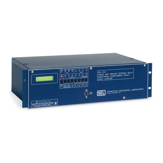
• Read meter and other data Password protection Figure 1.1: SEL-321 Front Panel (One I/O Board Version) Figure 1.2: SEL-321 Rear Panel (One I/O Board Version, showing conventional terminal blocks – other options are available) Introduction Date Code 20011026 SEL-321/321-1 Instruction Manual... -
Page 15: Figure 1.4: Three-Phase And Phase-Phase Distance Characteristics
Figure 1.3: SEL-321 Rear Panel (Two I/O Board Version, showing plug-in connectors option - other options are available) • Four mho zones • Two quadrilateral zones for OOS • Two load zones • Set only characteristics you need • All zones reversible Figure 1.4: Three-Phase and Phase-Phase Distance... -
Page 16: Figure 1.5: Ground Distance Characteristics
• Torque-controllable by distance and directional elements • One-cycle or electro- mechanical reset char- acteristics • Four instantaneous/ definite-time elements for Figure 1.6: Instantaneous, Definite-Time, and Time- negative-sequence and Overcurrent Characteristics for residual overcurrent Introduction Date Code 20011026 SEL-321/321-1 Instruction Manual... -
Page 17: Figure 1.7: Sel Ogic ® Control Equations Programmable Control Logic
• Default report is 11-cycles duration, 4 samples/cycle • Long event report is 11-cycles duration, 16 samples/cycle • Unfiltered report for computer analysis of data • Forty summaries are stored in nonvolatile memory Date Code 20011026 Introduction SEL-321/321-1 Instruction Manual... -
Page 18: Applications Highlights
• Time-stepped distance Subtransmission Lines • Ground directional overcurrent protection • Torque controlled time-overcurrent elements Lines with Transformers • Negative-sequence overcurrent protection Lines with Reactors • Overvoltage elements control reactor insertion and tripping Introduction Date Code 20011026 SEL-321/321-1 Instruction Manual... -
Page 19: Other Features
If you ordered your SEL relay with an electronic-level input option, references in the instruction manual to Current Inputs and Voltage Inputs should be noted accordingly. Since the input circuits are designed to accept electronic levels, do not subject them to Dielectric Strength, Date Code 20011026 Introduction SEL-321/321-1 Instruction Manual... -
Page 20: Maximum Continuous Rating
1 PU = 2000 A, Sensor Scaling Factor = 0.1 mV/A Secondary Input-Current Option = 2000+0.1 = 200 mV Since the SEL-321 Relay is set in secondary quantities and nonconventional sensor outputs are in primary quantities you must scale the relay settings using PTR (Potential Transformer Ratio) and CTR (Current Transformer Ratio). - Page 21 Ground Mho and Quadrilateral Distance Characteristics.............2-3 Out-of-Step (OOS) Characteristics....................2-3 Load-Encroachment Characteristics.....................2-4 Negative-Sequence Directional Characteristics ................2-5 Time-Overcurrent Elements (SEL-321 Base Version) ..............2-5 Time-Overcurrent Elements (SEL-321-1 Relay Only) ..............2-6 Instantaneous/Definite-Time Overcurrent Elements: Levels 1 - 4 ..........2-7 Additional Voltage Elements......................2-7 Phase Voltage Elements......................2-8 Zero-Sequence Overvoltage Element ...................2-8...
- Page 22 Table 2.12: Internal Elements.........................2-29 Table 2.13: Internal Element Summary ....................2-30 Table 2.14: Input/Output Contact Targets (One I/O Board Version, SEL-321 Relay Only) ....2-32 Table 2.15: Input/Output Contact Targets (Two I/O Board Version, SEL-321 Relay Only)....2-32 Table 2.16: Remote Bits (SEL-321-1 Relay Only).................2-32...
- Page 23 Table 2.20: Internal Elements (SEL-321-1 Relay Only) ................2-34 Table 2.21: Internal Element Summary (SEL-321-1 Relay Only) ............2-34 Table 2.22: Input/Output Contact Targets (One I/O Board Version, SEL-321-1 Relay Only) .....2-36 Table 2.23: Input/Output Contact Targets (Two I/O Board Version, SEL-321-1 Relay Only) ....2-37 Table 2.24: Input/Output Contact Targets Summary (One I/O Board Version and Two I/O Board...
- Page 24 Figure 2.52: Time Curve U3 ........................2-83 Figure 2.53: Time Curve U4 ........................2-83 Figure 2.54: Time Curve C1 ........................2-84 Figure 2.55: Time Curve C2 ........................2-84 Figure 2.56: Time Curve C3 ........................2-84 Figure 2.57: Time Curve C4 ........................2-84 Specifications Date Code 20011026 SEL-321/321-1 Instruction Manual...
-
Page 25: Section 2: Specifications
The relay accepts information which describes the line section in terms of positive- and zero- sequence secondary impedances. The fault location algorithm uses these replica impedances directly. The distance elements use the positive-sequence impedance angle for calculations. Date Code 20011026 Specifications SEL-321/321-1 Instruction Manual... -
Page 26: Enabling Distance Zones
(F = Forward, R = Reverse) HASE ISTANCE HARACTERISTICS Each phase mho zone has independent phase-to-phase overcurrent supervision. All instantaneous and time delayed outputs can be used in the programmable logic to create control, alarm, and indication schemes. Specifications Date Code 20011026 SEL-321/321-1 Instruction Manual... - Page 27 (OSBD), the relay logic prevents designated zones from tripping for up to two seconds. Negative-sequence overcurrent conditions, detected by the 50Q1 - 50Q4 elements, remove OOS blocking to permit tripping for unbalanced faults which may occur during swings. The OOS characteristics do not affect ground-fault protection. Date Code 20011026 Specifications SEL-321/321-1 Instruction Manual...
- Page 28 (minimum load impedance), and some margin, to ensure heavy loads remain inside the load characteristic. Settings Load-Out Region Load-In Region Minimum load impedance Load-angle limits PLAF (-90° to +90°) PLAR (90° to 270°) NLAF (-90° to +90°) NLAR (90° to 270°) Specifications Date Code 20011026 SEL-321/321-1 Instruction Manual...
- Page 29 Phase, negative-sequence, and residual time-overcurrent elements are available as enabled. Both US and IEC curve shapes are supported. The phase element uses the highest measured phase current, while the negative-sequence and residual current elements use 3I and I currents, respectively. Date Code 20011026 Specifications SEL-321/321-1 Instruction Manual...
- Page 30 • Zone 2 Phase Mho (M2P) • Load Encroachment • Zone 2 Ground Dist (Z2G) • 32QF (forward) • 32QR (reverse) • Nondirectional Reset delay setting choices permit one-cycle resetting or slow resetting, which emulates induction disk resetting. Specifications Date Code 20011026 SEL-321/321-1 Instruction Manual...
- Page 31 Possible applications might include undervoltage supervision of instantaneous overcurrent elements, local and remote overvoltage alarms, etc. Date Code 20011026 Specifications SEL-321/321-1 Instruction Manual...
-
Page 32: Phase Voltage Elements
Timer Settings Phase 21 Gnd 21 Zone/Level 1 67NL1D 67QL1D Zone/Level 2 Z2PD Z2GD 67NL2D 67QL2D Zone/Level 3 Z3PD Z3GD 67NL3D 67QL3D Zone/Level 4 Z4PD Z4GD 67NL4D 67QL4D Specifications Date Code 20011026 SEL-321/321-1 Instruction Manual... -
Page 33: Communications-Assisted Tripping Schemes
Set to OFF to ignore EBLKD and defeat echo input to ATB logic. Echo Time Delay P/U ETDPU Sets minimum time requirement for received PT, before echo begins. Set to OFF for no echo. Date Code 20011026 Specifications SEL-321/321-1 Instruction Manual... -
Page 34: Directional Comparison Unblocking (Dcub) Logic
Logic Outputs Same as POTT outputs Unblocking Block Disables tripping by the DCUB logic. Permissive Trip Receive PTRX Permissive trip signal receive input to POTT logic. Supporting Drawings: Figure 2.31 and Figure 2.32. 2-10 Specifications Date Code 20011026 SEL-321/321-1 Instruction Manual... -
Page 35: Directional Comparison Blocking (Dcb) Logic
Block trip receive signal extended by BTXD timer. Supporting Drawings: Figure 2.33 and Figure 2.34. For further information, request Application Guide 93-06: Applying the SEL-321 Relay to Directional Comparison Blocking (DCB) Schemes from your representative or the factory. Date Code 20011026... -
Page 36: Creating Other Tripping Schemes
Single-Pole Trip Applications. Assign inputs to DTA, DTB, and DTC. Assertion of an input causes the corresponding trip variable to assert. Figure 2.1 shows the necessary connections between the SEL-321 Relay and the communication equipment. Figure 2.1: Signal Connections Between Relay and Communication Equipment... -
Page 37: Other Logic
One-phase current is above the 3P50R threshold. This must remain asserted for REJO declaration. Remote-End-Just-Opened REJO Enables tripping by elements in the MTCS variable. Supporting Drawing: Figure 2.36. Date Code 20011026 Specifications 2-13 SEL-321/321-1 Instruction Manual... -
Page 38: Switch-Onto-Fault (Sotf) Logic
Settings ELOP = N or Y use the original loss- of-potential logic. Settings ELOP = N1, Y1, or Y2 use the advanced loss-of-potential logic. See Loss-of-Potential (LOP) Enable Setting (ELOP) in Section 5: Applications for a description of the LOP logic. 2-14 Specifications Date Code 20011026 SEL-321/321-1 Instruction Manual... -
Page 39: Pole-Discordance Logic
Sets time delay for checking the 52A input statuses following the dropout of a single-pole trip signal. Outputs Pole Discordance 1 Breaker 1 pole discordance. Pole Discordance 2 Breaker 2 pole discordance. Supporting Drawing: Figure 2.39. Date Code 20011026 Specifications 2-15 SEL-321/321-1 Instruction Manual... -
Page 40: Pole Open Logic
Timer Setting Stub Protection Coord. Delay 50MFD Define-time delay for 50MF. Output Stub Protection O/C Element 50MF Asserts for faults during LOP conditions if 50M asserted for 50MFD delay. Supporting Drawing: Figure 2.41. 2-16 Specifications Date Code 20011026 SEL-321/321-1 Instruction Manual... -
Page 41: Trip Coil Monitor (Tcm) Logic
Assign a relay input to monitor the device which initiates the potential transfer. The input assignment is PTXFR. For a five second period after asserting the PTXFR input, the Trip Suspicion logic delays tripping for 3 cycles. Date Code 20011026 Specifications 2-17 SEL-321/321-1 Instruction Manual... -
Page 42: Fault Identification Selection (Fids) Logic
16 inputs, IN1 - IN16. You assign functions to each of the inputs from the assignments listed in Table 2.4 by using the SET G command. The assigned input statuses are available in Relay Word rows 20 - 23 (see Table 2.9). 2-18 Specifications Date Code 20011026 SEL-321/321-1 Instruction Manual... -
Page 43: Table 2.4: Logic Input Assignment List
Trip Coil Monitor 2 TCM2 Monitors Breaker 2 trip coil Trip Coil Monitor, TCMA1 Monitors Breaker 1, A-phase trip coil A-phase 1 Trip Coil Monitor, TCMB1 Monitors Breaker 1, B-phase trip coil B-phase 1 Date Code 20011026 Specifications 2-19 SEL-321/321-1 Instruction Manual... - Page 44 Select the elements which trip for switch-onto-fault conditions • Select the elements which trip unconditionally • Select the elements which trip with communications assistance Figure 2.2 gives an overview of SEL control equations in the SEL-321 Relay. OGIC 2-20 Specifications Date Code 20011026 SEL-321/321-1 Instruction Manual...
- Page 45 Figure 2.2: SEL-321 SEL Control Equations Overview OGIC Programming SEL control equations is easy. OGIC 1. Use the SET G command to enter your input assignments into the global settings of the relay. (“Global” means that only one set of input assignments is permitted. There are six sets of logic and element settings.) Table 2.4 lists all available input assignment choices.
-
Page 46: Equation Programming
M1P + 27L contains three terms. The string OGIC 50H * !3P27 also contains three terms. The string TPA * SOTFE + TPB * SOTFE + TPC * SOTFE contains eleven terms. 2-22 Specifications Date Code 20011026 SEL-321/321-1 Instruction Manual... -
Page 47: Sel Ogic Control Equation Operator Order Of Operations
Programming an output equation to NA disables that output contact. Relay Elements Table 2.6 through Table 2.15 show the set of relay elements. For the SEL-321-1, use Table 2.6 through Table 2.9 and Table 2.16 through Table 2.24. Display any row of relay elements using the TARGET command and the TAR numbers in the left column of each table. -
Page 48: Table 2.7: Primary Elements
Zone 2 Mho and/or Quad. Distance, Instantaneous Zone 1 Mho and/or Quad. Distance, Instantaneous Zone 4 Phase Distance, Instantaneous Zone 3 Phase Distance, Instantaneous Zone 2 Phase Distance, Instantaneous Zone 1 Phase Distance, Instantaneous 2-24 Specifications Date Code 20011026 SEL-321/321-1 Instruction Manual... - Page 49 Phase Time-Overcurrent Timed Out ZLOAD Load Element SOTFE Switch-Onto-Fault Logic Enabled Trip Coil Monitor Alarm Reserved for future use Three Poles Open Single-Pole Open REJO Remote End Just Opened Condition Breaker 2 Phase Discordance Declaration Date Code 20011026 Specifications 2-25 SEL-321/321-1 Instruction Manual...
- Page 50 Carrier Stop for DCB (active if EDCB = Y) START Carrier Start for DCB (active if EDCB = Y) FIDEN FIDS Logic Enable FIDS logic selects C-phase FIDS logic selects B-phase FIDS logic selects A-phase 2-26 Specifications Date Code 20011026 SEL-321/321-1 Instruction Manual...
- Page 51 MBC1 Mho BC Phase Distance Zone 1, Instantaneous MBC2 Mho BC Phase Distance Zone 2, Instantaneous MBC3 Mho BC Phase Distance Zone 3, Instantaneous MBC4 Mho BC Phase Distance Zone 4, Instantaneous Date Code 20011026 Specifications 2-27 SEL-321/321-1 Instruction Manual...
-
Page 52: Table 2.9: Assigned Input Statuses
The XT, YT, and ZT elements are time-delayed pickup and dropout representations of X, Y, and Z, respectively. Use these variables in multiple masks or output equations, or when a general purpose timer is required. 2-28 Specifications Date Code 20011026 SEL-321/321-1 Instruction Manual... -
Page 53: Table 2.10: Intermediate Elements
OSB4 OSB3 OSB2 OSB1 50PP4 50PP3 50PP2 50PP1 ILOP SPT_EN 52AC 52AB 52AA 50AB4 50AB3 50AB2 50AB1 ATPC ATPB ATPA 50PPL 50CA4 50CA3 50CA2 50CA1 50BC4 50BC3 50BC2 50BC1 51NR 51QR 51PR Date Code 20011026 Specifications 2-29 SEL-321/321-1 Instruction Manual... -
Page 54: Table 2.13: Internal Element Summary
Residual Overcurrent Supervision, Zone 1 50CL Any C-phase Overcurrent Supervision Element Picked Up 50BL Any B-phase Overcurrent Supervision Element Picked Up 50AL Any A-phase Overcurrent Supervision Element Picked Up Reserved for Future Use 2-30 Specifications Date Code 20011026 SEL-321/321-1 Instruction Manual... - Page 55 CA Overcurrent Supervision, Zone 2 50CA1 CA Overcurrent Supervision, Zone 1 50BC4 BC Overcurrent Supervision, Zone 4 50BC3 BC Overcurrent Supervision, Zone 3 50BC2 BC Overcurrent Supervision, Zone 2 50BC1 BC Overcurrent Supervision, Zone 1 Date Code 20011026 Specifications 2-31 SEL-321/321-1 Instruction Manual...
-
Page 56: Table 2.14: Input/Output Contact Targets (One I/O Board Version, Sel-321 Relay Only)
Table 2.14 shows the status indicators for the input and output contacts for one I/O board relays. Table 2.15 shows status indicators for the input and output contacts for two I/O board relays. Table 2.14: Input/Output Contact Targets (One I/O Board Version, SEL-321 Relay Only) Status Indicators... -
Page 57: Table 2.17: Remote Bit Summary (Sel-321-1 Relay Only)
Table 2.17: Remote Bit Summary (SEL-321-1 Relay Only) Element Comment Remote Bit 8 Remote Bit 7 Remote Bit 6 Remote Bit 5 Remote Bit 4 Remote Bit 3 Remote Bit 2 Remote Bit 1 RB16 Remote Bit 16 RB15 Remote Bit 15... -
Page 58: Table 2.20: Internal Elements (Sel-321-1 Relay Only)
50CA3 50CA2 50CA1 50BC4 50BC3 50BC2 50BC1 51NR 51QR 51PR Table 2.21: Internal Element Summary (SEL-321-1 Relay Only) Element Comment RAG4 A-phase-Ground Resistance Blinder, Zone 4 RAG3 A-phase-Ground Resistance Blinder, Zone 3 RAG2 A-phase-Ground Resistance Blinder, Zone 2 RAG1 A-phase-Ground Resistance Blinder, Zone 1... - Page 59 Reserved For Future Use Reserved For Future Use Reserved For Future Use Reserved For Future Use 52AC Breaker(s) Auxiliary Contact Pole C 52AB Breaker(s) Auxiliary Contact Pole B 52AA Breaker(s) Auxiliary Contact Pole A Date Code 20011026 Specifications 2-35 SEL-321/321-1 Instruction Manual...
-
Page 60: Table 2.22: Input/Output Contact Targets (One I/O Board Version, Sel-321-1 Relay Only)
Table 2.22 shows the status indicators for the input and output contacts for one I/O board relays. Table 2.23 shows status indicators for the input and output contacts for two I/O board relays. Table 2.22: Input/Output Contact Targets (One I/O Board Version, SEL-321-1 Relay Only) Status Indicators OUT1... -
Page 61: Trip Logic
RMB7 RMB6 RMB5 RMB4 RMB3 RMB2 RMB1 Table 2.24: Input/Output Contact Targets Summary (One I/O Board Version and Two I/O Board Version, SEL-321-1 Relay Only) Element Comment MIRBRK Break detected on M communication channel IRRORED MIRFRA Framing error detected on M... -
Page 62: Selecting Single-Pole Or Three-Pole Tripping Logic
Variable 3PT indicates three-pole trips. Single-Pole Tripping Conditions When the single-pole tripping logic is active, the SEL-321 Relay trips single-pole for the following trip conditions: • Zone 1 SLG faults detected by the ground distance elements •... -
Page 63: Mto (Switch-Onto-Fault Trip Variable)
Table 2.25 shows what combinations of asserted logic inputs select which group. Table 2.25: Setting Group Selections Group Selected Group designated by the GROUP Command Group 1 Group 2 Group 3 Group 4 Group 5 Group 6 Group designated by the GROUP Command Date Code 20011026 Specifications 2-39 SEL-321/321-1 Instruction Manual... -
Page 64: Active Groups And Group Variables
LOCAT = R for radial applications. Set LOCAT = N to disable the fault location feature. One of the elements in Table 2.26 must assert in the event report data for the relay to calculate a fault location. 2-40 Specifications Date Code 20011026 SEL-321/321-1 Instruction Manual... -
Page 65: Front-Panel Targets
The LCD display shows the detailed information pertaining to a fault detected by the relay, displaying metering information, relay self-test status information, etc. The LEDs designations are shown in Figure 2.3. Figure 2.3: SEL-321 Front-Panel Targeting General Target LED Description Under normal operating conditions, only the enable (EN) LED is illuminated. Other LEDs illuminate when the relay trips. -
Page 66: Table 2.27: Inst And Time Led Qualifying Elements
• MAG1 - MAG4 • XAG1 - XAG4 • MAB1 - MAB4 if 21AB < 21BC and 21CA and │I │ > │0.3⋅I │ • M1P - M4P and │I │ < │0.3⋅I │ 2-42 Specifications Date Code 20011026 SEL-321/321-1 Instruction Manual... - Page 67 • 67Q1 * ZONE 1 LED conditions satisfied • 67Q2 * ZONE 2 LED conditions satisfied • 67Q3 * ZONE 3 LED conditions satisfied • 67Q4 * ZONE 4 LED conditions satisfied • 50H • 50HH • 50MF Date Code 20011026 Specifications 2-43 SEL-321/321-1 Instruction Manual...
-
Page 68: Communications Ports Specifications
Port 3 IRIG-B Comment Description Type EIA-232 Time Code Protocol SEL = Standard Communica- tions LMD (SEL-321-1 Relay Only) LMD = Distributed Port Switch Protocol (See Appendix G) MB = Relay-to-Relay digital communications only one port (See Appendix H) Baud Rate... -
Page 69: Internal Time Clock Time-Code Synchronization Specifications
This report may be retrieved using the STATUS command. Table 2.29 shows relay actions for any self-test condition: warning (W) or failure (F). Date Code 20011026 Specifications 2-45 SEL-321/321-1 Instruction Manual... -
Page 70: Table 2.29: Self-Test Summary
30 mV Latched * SEL-321-1 Relays manufactured since September 1996 are equipped with a new global setting, ERESTART. When ERESTART = Y, the relay performs a power-up reset when a CR_RAM self-test failure is detected. This reset clears the relay date, time, and event history. On reset, if the failure condition is still present, the relay is disabled. -
Page 71: Technical Specifications (1 A Nominal Relay)
0.2 - 20 A, ±0.01 A, ±3% of setting • Supervises OOS logic Residual Secondary Pickup Setting Range: 0.1 - 20 A, ±0.01 A, ±3% of setting Transient Overreach: ±5% of pickup • Supervises ground distance Date Code 20011026 Specifications 2-47 SEL-321/321-1 Instruction Manual... - Page 72 DCB Carrier Coordination Time Delay: 0 - 60 cycles Short Delay Time Delay: 0 - 2000 cycles Long Delay Time Delay: 0 - 8000 cycles Loss-of-Potential Set Time Delay: 1 - 60 cycles 2-48 Specifications Date Code 20011026 SEL-321/321-1 Instruction Manual...
-
Page 73: Technical Specifications (5 A Nominal Relay)
1.0 - 100 A, ±0.05 A, ±3% of setting • Supervises OOS logic Residual Secondary Pickup Setting Range: 0.5 - 100 A, ±0.05 A, ±3% of setting Transient Overreach: ±5% of pickup • Supervises ground distance Date Code 20011026 Specifications 2-49 SEL-321/321-1 Instruction Manual... - Page 74 DCB Carrier Coordination Time Delay: 0 - 60 cycles Short Delay Time Delay: 0 - 2000 cycles Long Delay Time Delay: 0 - 8000 cycles Loss-of-Potential Set Time Delay: 1 - 60 cycles 2-50 Specifications Date Code 20011026 SEL-321/321-1 Instruction Manual...
-
Page 75: General Specifications
L/R = 40 ms 125 V 0.3 A L/R = 40 ms 250 V 0.2 A L/R = 40 ms Note: Make per IEEE C37.90–1989; Breaking and Cyclic Capacity per IEC 60255-23–1994. Date Code 20011026 Specifications 2-51 SEL-321/321-1 Instruction Manual... - Page 76 Fixed level-sensitive inputs 250 Vdc: Pickup 200–300 Vdc; dropout 150 Vdc 125 Vdc: Pickup 105–150 Vdc; dropout 75 Vdc 48 Vdc: Pickup 38.4–60 Vdc; dropout 28.8 Vdc Note: Nominal input current is 4 mA. 2-52 Specifications Date Code 20011026 SEL-321/321-1 Instruction Manual...
- Page 77 IEC 60255-21-1–1988, Class 1 IEC 60255-21-2–1988, Class 1 Exception: 4.1.4 Vibration Response Amplitude Tolerance increased to ±25% (two I/O board version – rear-panel plug-in connectors option only) Safety Impulse: IEC 60255-5–1977, 0.5 J, 5000 V Date Code 20011026 Specifications 2-53 SEL-321/321-1 Instruction Manual...
-
Page 78: Figure 2.4: Logic Symbol Legend
Figure 2.4: Logic Symbol Legend 2-54 Specifications Date Code 20011026 SEL-321/321-1 Instruction Manual... -
Page 79: Figure 2.5: Zone 1 Mho Phase Distance Element Logic
Figure 2.5: Zone 1 Mho Phase Distance Element Logic Figure 2.6: Zone 2 Mho Phase Distance Element Logic Date Code 20011026 Specifications 2-55 SEL-321/321-1 Instruction Manual... -
Page 80: Figure 2.7: Zone 3 Mho Phase Distance Element Logic
Figure 2.7: Zone 3 Mho Phase Distance Element Logic Figure 2.8: Zone 4 Mho Phase Distance Element Logic 2-56 Specifications Date Code 20011026 SEL-321/321-1 Instruction Manual... -
Page 81: Figure 2.9: Supervisory Phase-To-Phase Overcurrent Elements
Figure 2.9: Supervisory Phase-to-Phase Overcurrent Elements Figure 2.10: Zone 1 Mho Ground Distance Element Logic Date Code 20011026 Specifications 2-57 SEL-321/321-1 Instruction Manual... -
Page 82: Figure 2.11: Zone 2 Mho Ground Distance Element Logic
Figure 2.11: Zone 2 Mho Ground Distance Element Logic Figure 2.12: Zone 3 Mho Ground Distance Element Logic Figure 2.13: Zone 4 Mho Ground Distance Element Logic 2-58 Specifications Date Code 20011026 SEL-321/321-1 Instruction Manual... -
Page 83: Figure 2.14: Zone 1 Quadrilateral Ground Distance Element Logic
Figure 2.14: Zone 1 Quadrilateral Ground Distance Element Logic Figure 2.15: Zone 2 Quadrilateral Ground Distance Element Logic Figure 2.16: Zone 3 Quadrilateral Ground Distance Element Logic Figure 2.17: Zone 4 Quadrilateral Ground Distance Element Logic Date Code 20011026 Specifications 2-59 SEL-321/321-1 Instruction Manual... -
Page 84: Figure 2.18: Supervisory Phase Overcurrent Elements
Figure 2.18: Supervisory Phase Overcurrent Elements 2-60 Specifications Date Code 20011026 SEL-321/321-1 Instruction Manual... -
Page 85: Figure 2.19: Out-Of-Step Distance Element Logic
Figure 2.19: Out-of-Step Distance Element Logic Date Code 20011026 Specifications 2-61 SEL-321/321-1 Instruction Manual... -
Page 86: Figure 2.20: Out-Of-Step Block And Trip Logic
Figure 2.20: Out-of-Step Block and Trip Logic 2-62 Specifications Date Code 20011026 SEL-321/321-1 Instruction Manual... -
Page 87: Figure 2.21: Load-Encroachment Logic
Figure 2.21: Load-Encroachment Logic Date Code 20011026 Specifications 2-63 SEL-321/321-1 Instruction Manual... -
Page 88: Figure 2.22: Negative-Sequence Directional Element Logic
Figure 2.22: Negative-Sequence Directional Element Logic 2-64 Specifications Date Code 20011026 SEL-321/321-1 Instruction Manual... -
Page 89: Figure 2.23: Phase Time-Overcurrent Element Logic (Sel-321 Relay Base Version)
Figure 2.23: Phase Time-Overcurrent Element Logic (SEL-321 Relay Base Version) Figure 2.24: Phase Time-Overcurrent Element Logic (SEL-321-1 Relay Only) Date Code 20011026 Specifications 2-65 SEL-321/321-1 Instruction Manual... -
Page 90: Figure 2.25: Negative-Sequence Time-Overcurrent Element Logic
Figure 2.25: Negative-Sequence Time-Overcurrent Element Logic 2-66 Specifications Date Code 20011026 SEL-321/321-1 Instruction Manual... -
Page 91: Figure 2.26: Residual Time-Overcurrent Element Logic
Figure 2.26: Residual Time-Overcurrent Element Logic Date Code 20011026 Specifications 2-67 SEL-321/321-1 Instruction Manual... -
Page 92: Figure 2.27: Negative-Sequence Overcurrent Element Logic For Levels 1 - 4
Figure 2.27: Negative-Sequence Overcurrent Element Logic for Levels 1 - 4 2-68 Specifications Date Code 20011026 SEL-321/321-1 Instruction Manual... -
Page 93: Figure 2.28: Residual Overcurrent Element Logic For Levels 1 - 4
Figure 2.28: Residual Overcurrent Element Logic for Levels 1 - 4 Date Code 20011026 Specifications 2-69 SEL-321/321-1 Instruction Manual... -
Page 94: Figure 2.29: Voltage Element Logic
Figure 2.29: Voltage Element Logic 2-70 Specifications Date Code 20011026 SEL-321/321-1 Instruction Manual... -
Page 95: Figure 2.30: Positive-Sequence Overvoltage Element Logic
Figure 2.30: Positive-Sequence Overvoltage Element Logic Figure 2.31: Permissive Overreaching Transfer Trip Scheme Logic Date Code 20011026 Specifications 2-71 SEL-321/321-1 Instruction Manual... -
Page 96: Figure 2.32: Directional Comparison Unblocking Scheme Logic
Figure 2.32: Directional Comparison Unblocking Scheme Logic Figure 2.33: Directional Comparison Blocking Scheme Logic - 1 of 2 Figure 2.34: Directional Comparison Blocking Scheme Logic - 2 of 2 2-72 Specifications Date Code 20011026 SEL-321/321-1 Instruction Manual... -
Page 97: Figure 2.35: Zone 1 Extension Logic
Figure 2.35: Zone 1 Extension Logic Figure 2.36: Remote-End-Just-Opened Logic Figure 2.37: Switch-Onto-Fault Enable Logic Date Code 20011026 Specifications 2-73 SEL-321/321-1 Instruction Manual... -
Page 98: Figure 2.38: Loss-Of-Potential Logic
(Setting) Relay Enable Word Bits Block Loss-of- ILOP Potential * LPVNOM Logic (Factory Setting) ELOP = Y1,Y2 (Setting) ELOP = Y (Setting) DWG: M321001 * See Appendix F Figure 2.38: Loss-of-Potential Logic 2-74 Specifications Date Code 20011026 SEL-321/321-1 Instruction Manual... -
Page 99: Figure 2.39: Pole-Discordance And Trip During Pole Open Logic
Figure 2.39: Pole-Discordance and Trip During Pole Open Logic Date Code 20011026 Specifications 2-75 SEL-321/321-1 Instruction Manual... -
Page 100: Figure 2.40: Pole Open Logic
Figure 2.40: Pole Open Logic Figure 2.41: Stub Protection Logic Figure 2.42: Trip Coil Monitor Logic 2-76 Specifications Date Code 20011026 SEL-321/321-1 Instruction Manual... -
Page 101: Figure 2.43: Close Logic
Figure 2.43: Close Logic Figure 2.44: Trip Suspicion Logic Figure 2.45: Open Phase Alarm Logic Date Code 20011026 Specifications 2-77 SEL-321/321-1 Instruction Manual... -
Page 102: Figure 2.46: Trip Decision Logic For Phase A
Figure 2.46: Trip Decision Logic for Phase A Figure 2.47: Trip Latch Logic 2-78 Specifications Date Code 20011026 SEL-321/321-1 Instruction Manual... -
Page 103: Distance Element Operating Time Curves At Nominal Frequency
URVES AT OMINAL REQUENCY Figure 2.49 shows operating times for the SEL-321 Relay distance elements. The diagrams show operating times at each test point. Operating times include output contact closure time (for standard and interrupting duty contact outputs). For the distance element test, a fault was applied at a location representing a percentage of the Zone 1 relay reach setting. -
Page 104: Time-Overcurrent Curve Equations
URVE QUATIONS Both US and IEC time-overcurrent curves are provided in the SEL-321 Relay. Use the SET command to select the curve characteristics you desire. Refer to Section 3: Communications for a complete description of the use of the SET command and selection of time-overcurrent characteristics. -
Page 105: Equations For Us Curves
Curve U3: Very Inverse - See Figure 2.52 ⋅ é ù 0963 ê ë ú û − − Curve U4: Extremely Inverse - See Figure 2.53 ⋅ é ù 0352 ê ë ú û − − Date Code 20011026 Specifications 2-81 SEL-321/321-1 Instruction Manual... -
Page 106: Equations For Iec Curves
Curve C3: Extremely Inverse - See Figure 2.56 ⋅ é ù ê ë ú û − − Curve C4: Long Time Backup - See Figure 2.57 ⋅ é ù ê ë ú û − − 2-82 Specifications Date Code 20011026 SEL-321/321-1 Instruction Manual... -
Page 107: Figure 2.50: Time Curve U1
Figure 2.50: Time Curve U1 Figure 2.51: Time Curve U2 Figure 2.53: Time Curve U4 Figure 2.52: Time Curve U3 Date Code 20011026 Specifications 2-83 SEL-321/321-1 Instruction Manual... -
Page 108: Figure 2.54: Time Curve C1
Figure 2.54: Time Curve C1 Figure 2.55: Time Curve C2 Figure 2.56: Time Curve C3 Figure 2.57: Time Curve C4 2-84 Specifications Date Code 20011026 SEL-321/321-1 Instruction Manual... - Page 109 TABLE OF CONTENTS SECTION 3: COMMUNICATIONS ............3-1 Introduction...........................3-1 Communications Protocol......................3-1 Software Protocol........................3-1 Additional Software Protocol (SEL-321-1 Relay Only) ............3-2 Hardware Protocol ........................3-3 Alarm Conditions........................3-3 Main Board Jumpers ......................3-3 Automatic Messages ......................3-4 Command Characteristics ......................3-4 Changing Access Levels .......................3-6 Command Format .........................3-6 Description of Commands ......................3-6...
- Page 110 TABLES Table 3.1: Commands With Alarm Conditions ..................3-3 Table 3.2: Hardware Jumpers That Affect Commands................3-3 Table 3.3: SEL-321-1 Relay CONTROL Subcommands ...............3-10 Table 3.4: History Report Description....................3-13 Table 3.5: Variations on the SET Command ..................3-18 Table 3.6: Editing Keys for SET Commands ..................3-19 Table 3.7: Group SET Fail Messages .....................3-20...
-
Page 111: Section 3: Communications
This section explains the communications protocol. It also gives examples of commands and front-panel operations for the SEL-321 Relay. You set and operate the SEL-321 Relay via front-panel controls and serial communications interfaces. The serial interfaces may be connected to a computer terminal and/or modem. Relay communication serves these purposes: •... -
Page 112: Additional Software Protocol (Sel-321-1 Relay Only)
(hold down the Control key and press X) Additional Software Protocol (SEL-321-1 Relay Only) The SEL-321-1 Relay includes additional software protocol which supports limited multidrop, fast meter, and compressed ASCII. Refer to Appendix G for more information on the additional protocols. -
Page 113: Hardware Protocol
4. If RTS_CTS = Y, the relay does not send characters until the CTS input is asserted. Alarm Conditions The SEL-321 Relay asserts the ALARM output until self-tests pass when power is applied and at any diagnostic test failure. In addition to these, the ALARM output pulses with the commands and conditions shown in Table 3.1. -
Page 114: Automatic Messages
SEE THE STATUS COMMAND FOR THE FORMAT OF THE STATUS REPORT Summary Event Report: SEE THE EVENT REPORTING SECTION FOR THE FORMAT OF THE SUMMARY EVENT REPORT On CR_RAM failure, if ERESTART = Y (SEL-321-1 Relay only): EXAMPLE: BUS B, BREAKER 3 Date: 02/01/93 Time: 23:31:17.489... - Page 115 Each level has an associated screen prompt and password. Figure 3.1 shows the access levels, passwords, prompts, commands available from each access level, and commands that move you between access levels. Figure 3.1: Access Level Relationships Date Code 20011026 Communications SEL-321/321-1 Instruction Manual...
-
Page 116: Changing Access Levels
The following display indicates successful access: =>2ACCESS <ENTER> 2ACCESS <ENTER> 2ACCESS <ENTER> 2ACCESS <ENTER> Password: ? TAIL <ENTER> TAIL <ENTER> TAIL <ENTER> TAIL <ENTER> EXAMPLE: BUS B, BREAKER 3 Date: 02/01/93 Time: 15:10:58.903 Level 2 =>> Communications Date Code 20011026 SEL-321/321-1 Instruction Manual... -
Page 117: Access
To use the CC element for breaker closing, program the CC element to an output contact using the SET L command. For example, if you want to use Output 15 to close the breaker, set OUT15 = CC. Date Code 20011026 Communications SEL-321/321-1 Instruction Manual... -
Page 118: Comm
Summary for Mirrored Bits Channel For 04/05/00 17:18:12.993 to 04/11/98 10:45:08.993 Total failures Last error Re-sync Relay disabled Data error Longest failure 0 00:00:00.499 Re-sync Underrun Unavailability 0.000688 % Overrun Parity error Framing error => Communications Date Code 20011026 SEL-321/321-1 Instruction Manual... -
Page 119: Control N (Sel-321-1 Relay Only)
(Y/N) ?” is displayed. Typing N <ENTER> aborts the clearing operation with the message “Canceled.” CONTROL n (SEL-321-1 Relay Only) The CONTROL command is a two-step, Access Level 2 command that allows you to control Relay Word bits RB1 through RB16. At the Access Level 2 prompt, type CONTROL, a space, and the number of the bit you wish to control (1-16). -
Page 120: Copy M N
CONTROL 5 <ENTER> CONTROL RB5: PRB 5 3 <ENTER> PRB 5 3 <ENTER> PRB 5 3 <ENTER> PRB 5 3 <ENTER> =>> Table 3.3: SEL-321-1 Relay CONTROL Subcommands Subcommand Description SRB n Set Remote Bit n CRB n Clear Remote Bit n... -
Page 121: Event
The GROUP command does not clear the event report buffer. If the active group is changed, the relay pulses the ALARM output contacts and transmits the following message to ports designated automatic: Date Code 20011026 Communications 3-11 SEL-321/321-1 Instruction Manual... -
Page 122: History
5 06/20/92 00:31:20.732 BC 36.01 TIME B C 6 06/20/92 00:31:19.655 BC 36.08 TIME B C 7 06/20/92 00:31:18.562 BC 35.98 TIME B C 8 06/20/92 00:31:17.482 BC 36.25 TIME B C 3-12 Communications Date Code 20011026 SEL-321/321-1 Instruction Manual... -
Page 123: Irig
If the relay reads the time code successfully, it updates the internal clock/calendar time and date to the time-code reading. The relay then transmits a message with relay ID, date, and time. Date Code 20011026 Communications 3-13 SEL-321/321-1 Instruction Manual... -
Page 124: Loop
Are you sure (Y/N) ? N <ENTER> N <ENTER> N <ENTER> N <ENTER> Canceled. =>> To disable looped back mode before the selected number of minutes, reissue the LOOP command with the R parameter. 3-14 Communications Date Code 20011026 SEL-321/321-1 Instruction Manual... -
Page 125: Meter
(Y/N) ?" Answering Y <ENTER> again closes the TRIP output relay as described above. If the port is designated AUTO, a summary event report is displayed. If the Breaker Jumper (P7: J106) is not in place, the relay responds: "Aborted: Breaker Jumper Not in Place." Date Code 20011026 Communications 3-15 SEL-321/321-1 Instruction Manual... -
Page 126: Password
Password Jumper (P7: J105) on the main board. See Jumper Settings in Section 6: Installation for details. With no password protection, you may gain access without knowing the passwords and view or change active passwords and settings. Passwords may not be changed from the front panel. 3-16 Communications Date Code 20011026 SEL-321/321-1 Instruction Manual... -
Page 127: Pulse N T (Sel-321-1 Relay Only)
PULSE n t (SEL-321-1 Relay Only) PULSE closes an output contact for testing or control purposes. Close any output contact for 0.125 - 1.0 seconds by executing the command in Access Level 2. Execute the command PULSE n t, where n is the number of the contact you wish to close and t is the time, in seconds, the contact remains closed. - Page 128 Program above condi- tions for Group 1 SET L OUT2 Program logic for active group starting at OUT2 entry SET L 1 OUT2 Program logic for Group 1 starting at OUT2 entry 3-18 Communications Date Code 20011026 SEL-321/321-1 Instruction Manual...
-
Page 129: Set N
SET 2 <ENTER> SET 2 <ENTER> GROUP 2 Line Terminal Relay Identifier: (17 Characters) RELID =SEL-321 POTT Terminal Identifier: (39 Characters) TRMID =EXAMPLE: BUS B, BREAKER 3 Positive-seq. Line Impedance Magnitude: (ohms sec.) Z1MAG = 7.80 Positive-seq. Line Impedance Angle: (degrees) Z1ANG = 83.97... - Page 130 Enabled distance element must not be OFF. Previously disabled distance element must be given a value. Enabled supervisory element must not be Previously disabled supervisory element must OFF. be given a value. 3-20 Communications Date Code 20011026 SEL-321/321-1 Instruction Manual...
- Page 131 51Q with Z2G. ELE must be Y to torque-control 51P with ZLIN and ZLOUT are disabled if ELE = N. ZLIN or ZLOUT. (Applies to SEL-321-1 (Applies to SEL-321-1 Relay only) Relay only) Table 3.8: SET or SET G Warning Messages...
-
Page 132: Showset
Level 2 Access. The SHOWSET command results in the following display: =>SHOWSET 2 <ENTER> SHOWSET 2 <ENTER> SHOWSET 2 <ENTER> SHOWSET 2 <ENTER> GROUP 2 RELID =SEL-321 POTT TRMID =EXAMPLE: BUS B, BREAKER 3 Z1MAG = 7.80 Z1ANG = 83.97 Z0MAG = 24.79 Z0ANG = 81.46 LOCAT = Y = 100.00 CTR... -
Page 133: Set G
TGR defines the time, in seconds, the relay delays before switching groups. ERESTART enables SEL-321-1 Relays to restart once on detection of a CR_RAM self-test failure. Below are shown the default global settings (one I/O board version - 8 inputs): =>>SET G <ENTER>... -
Page 134: Showset G
OUT1 through OUT11. For the two I/O board version of the relay, the second I/O board output settings start with OUT17 regardless of the type of the first I/O board. Some examples of 3-24 Communications Date Code 20011026 SEL-321/321-1 Instruction Manual... - Page 135 =M2P + Z2G + 51NP + 51QP + 50H + LOP*52AA1 OUT1 =3PT OUT2 =3PT OUT3 =CC OUT4 =KEY OUT5 =NA OUT6 =NA OUT7 =NA OUT8 =NA OUT9 =NA OUT10 =NA OUT11 =NA OUT12 =NA Date Code 20011026 Communications 3-25 SEL-321/321-1 Instruction Manual...
- Page 136 OUT5 =NA OUT6 =NA OUT7 =NA OUT8 =NA OUT9 =NA OUT10 =NA OUT11 =NA Press RETURN to continue OUT12 =NA OUT13 =NA OUT14 =NA OUT15 =NA TMB1 =NA TMB2 =NA TMB3 =NA 3-26 Communications Date Code 20011026 SEL-321/321-1 Instruction Manual...
-
Page 137: Showset L
=M2P + Z2G + 51NP + 51QP + 50H + LOP*52AA1 OUT1 =3PT OUT2 =3PT OUT3 =CC OUT4 =KEY OUT5 =NA OUT6 =NA OUT7 =NA OUT8 =NA OUT9 =NA OUT10 =NA OUT11 =NA Date Code 20011026 Communications 3-27 SEL-321/321-1 Instruction Manual... -
Page 138: Set P
AUTO setting for Port 3. The following display shows setting prompts for Port 1. You can also make settings from the front panel (see Setting Changes via Front Panel under LCD Functions and Front-Panel Commands). Note: FAST_OP setting included in SEL-321-1 Relay only. =>>SET P SET P 1 <ENTER>... -
Page 139: Showset P
(parameters may be entered in any order). Table 3.12 describes the settings displayed with the SHOWSET P command. See Section 2: Specifications for details on communications ports. Note: FAST_OP setting included in SEL-321-1 Relay only. =>SHOWSET P <ENTER> SHOWSET P <ENTER>... -
Page 140: Status
11.93 -12.09 15.02 -15.21 TEMP CR_RAM EEPROM SETTINGS 26.1 Relay Enabled => Table 3.13 describes the STATUS report. For a description of self-test and test parameters, see Self-Test in Section 2: Specifications. 3-30 Communications Date Code 20011026 SEL-321/321-1 Instruction Manual... - Page 141 Calibration valid settings, and Group LOGVAL settings. If any setting is set to NO, relay protection is disabled and GROUP, LOGIC, CAL, or GLOBAL indicates invalid settings class. Otherwise, OK is displayed. Date Code 20011026 Communications 3-31 SEL-321/321-1 Instruction Manual...
-
Page 142: Target
(1 - 32000) after the target number. Enter TAR 44 1000 to repeatedly view the relay inputs on an SEL-321-1 Relay with one I/O board. -
Page 143: Time
=>TRIGGER <ENTER> TRIGGER <ENTER> TRIGGER <ENTER> TRIGGER <ENTER> Triggered => EXAMPLE: BUS B, BREAKER 3 Date: 12/01/92 Time: 00:03:34.892 Event: EXTC Location: $$$$$$ Frequency: 60.0 Targets: EN V1 Mem: 0.0 / 180 => Date Code 20011026 Communications 3-33 SEL-321/321-1 Instruction Manual... -
Page 144: Front-Panel Operation
RONT ANEL PERATION The SEL-321 Relay front panel, shown in Figure 3.2, includes a 2-line, 16-character LCD display, 16 LED target/indicators and eight pushbuttons for enhanced communications. Figure 3.2: SEL-321 Relay Front-Panel Display LCD F UNCTIONS AND RONT ANEL OMMANDS The LCD display shows fault detection information, metering information, target reset and status display, and self-test status. -
Page 145: Front-Panel Reset
Table 3.15 shows a typical TARGET command dialog. The last target row is 40 for a relay with one I/O board, and is 43 for a relay with two I/O boards. Date Code 20011026 Communications 3-35 SEL-321/321-1 Instruction Manual... -
Page 146: Fault Command
Comment FAULT Displays Date/Time of first event record. 1 DATE 12/01/92 TIME 2342:51.732 Displays second field of first event record, → 1 DATE 12/01/92 showing event faulted phase and type. TYPE: 1ABC 3-36 Communications Date Code 20011026 SEL-321/321-1 Instruction Manual... -
Page 147: Meter Display
When you select STATUS, a STATUS report is displayed. The first row indicates if a warning or failure state exists, or if all self-tests have passed. Use the (↑) and (↓) keys to scroll through the Date Code 20011026 Communications 3-37 SEL-321/321-1 Instruction Manual... - Page 148 Pressing (↑) selects the next categories. ↑ OS:IA = 0 ↓ OS:IB = 0 ↑ ↑ OS:IC = 0 ↓ OS:VA = 0 ↑ OS:VB = 0 ↑ ↓ OS:VC = 0 3-38 Communications Date Code 20011026 SEL-321/321-1 Instruction Manual...
-
Page 149: Diagnostic Messages
SELECT ↑ ↓ ← → up the list. Use the SELECT button to select a settings category. The setting categories appear in the order listed below. Line Terminal Dist Zone Enable Zones/Levels Dir Date Code 20011026 Communications 3-39 SEL-321/321-1 Instruction Manual... - Page 150 Z1P = 6.24 Use the (←) and (→) arrow to select the previous or following category. Next variable Z2P is displayed within Phase ↓ Phase Distance Distance settings. Z2P = 9.36 3-40 Communications Date Code 20011026 SEL-321/321-1 Instruction Manual...
- Page 151 EXIT or CANCEL to resume. EXIT If settings are OK, changes are saved and display DEFAULT defaults to information shown before SET button DISPLAY was pushed. Date Code 20011026 Communications 3-41 SEL-321/321-1 Instruction Manual...
- Page 152 Press SELECT to enter edit mode. SELECT ↑ ↓ ← → SELECT Shows present protocol setting for this port. Press SET P 1 (↓) to move to next setting category for Port 1. PROTOCOL = SEL 3-42 Communications Date Code 20011026 SEL-321/321-1 Instruction Manual...
- Page 153 Press (← TIMEOUT = +0000000 or →) to move from digit to digit. Press (↑ or ↓) to change the underscored digit. Press SELECT to save this setting and move to next category. Date Code 20011026 Communications 3-43 SEL-321/321-1 Instruction Manual...
- Page 154 SELECT to save this choice and move to next RTS_CTS = Y setting category for Port 1. SELECT Press SELECT again to save settings and exit the Save Settings SET P edit session. Press CANCEL to abort new Yes/No? settings. 3-44 Communications Date Code 20011026 SEL-321/321-1 Instruction Manual...
-
Page 155: Sel-321-1 Target Information
SEL-321-1 TARGET INFORMATION SEL-321-1 Relay Status Indicators INST TIME COMM SOTF ZONE1 ZONE2 ZONE3 ZONE4 Z4GT Z3GT Z2GT M4PT M3PT M2PT 67Q4 67Q3 67Q2 67Q1 67N4 67N3 67N2 67N1 67Q4T 67Q3T 67Q2T 67N4T 67N3T 67N2T 3P27 50MF 51NT 51QT 51PT... - Page 156 SEL-321-1 TARGET INFORMATION SEL-321-1 Relay – One I/O Board Version Status Indicators OUT1 OUT2 OUT3 OUT4 OUT5 OUT6 OUT7 OUT8 OUT9 OUT10 OUT11 OUT12 OUT13 OUT14 OUT15 !ALARM TMB8 TMB7 TMB6 TMB5 TMB4 TMB3 TMB2 TMB1 MIRBRK MIRFRA MIRPAR MIROVR...
-
Page 157: Sel-321 Relay Command Summary
SEL-321 RELAY COMMAND SUMMARY Access Level 0 ACCESS Answer password prompt (if password protection is enabled) to enter Access Level 1. Three unsuccessful attempts pulse ALARM contacts closed for one second. Access Level 1 2ACCESS Answer password prompt (if password protection is enabled) to enter Access Level 2. - Page 158 Use SET P n to edit Port n's settings. Changes active port's settings. TARGET Shows target values, and defines target group for display. TAR n displays target row n. TAR R command resets front panel targets to TAR 1. Command Summary Date Code 20011026 SEL-321 Instruction Manual...
-
Page 159: Sel-321-1 Relay Command Summary
SEL-321-1 RELAY COMMAND SUMMARY Access Level 0 ACCESS Answer password prompt (if password protection is enabled) to enter Access Level 1. Three unsuccessful attempts pulse ALARM contacts closed for one second. Access Level 1 2ACCESS Answer password prompt (if password protection is enabled) to enter Access Level 2. - Page 160 Specifies currently selected group. Use GROUP n to change selected group to n. OPEN Asserts trip condition. Access Level 2 CONTROL n Allows you to control Relay Word bits RB1 through RB16. (SEL-321-1 only) COPY m n Copies settings and logic from setting Group m to Group n. LOOP Enables M...
- Page 161 Firmware Identification ......................4-12 TABLES Table 4.1: Event Report Triggering Actions ....................4-1 Table 4.2: Event Report Fault Type and Fault Location Enabling Elements...........4-1 Table 4.3: Event Record Type ........................4-2 Table 4.4: Event Types ..........................4-3 Date Code 20011026 Event Reporting SEL-321/321-1 Instruction Manual...
-
Page 163: Section 4: Event Reporting
Table 4.2: Event Report Fault Type and Fault Location Enabling Elements Fault Type Elements Phase-phase or three-phase Single-Line-Ground 67N1 67N2 67N3 67N4 51NP Event records taken with no triggering relay elements have the type shown in Table 4.3. Date Code 20011026 Event Reporting SEL-321/321-1 Instruction Manual... -
Page 164: Summary Event Report
• Front panel relay targets asserted at the last row of the event report • The magnitude and angle of positive-sequence polarizing voltage memory at the time of trigger Event Reporting Date Code 20011026 SEL-321/321-1 Instruction Manual... -
Page 165: Default Event Report
C = A*B, the filtered report would show A and B true, but C false, because A and B were not picked up at the same time. Date Code 20011026 Event Reporting SEL-321/321-1 Instruction Manual... -
Page 166: Long Event Report
CTR from group active at time of trigger. Sampled, filtered value, multiplied by CTR from group active at time of trigger. Sampled, filtered value, multiplied by PTR from group active at time of trigger. Event Reporting Date Code 20011026 SEL-321/321-1 Instruction Manual... -
Page 167: Relay Element Columns Data
If Zone 2 AB phase-phase distance element (MAB2) set, not ZAB1 If Zone 3 AB phase-phase distance element (MAB3) set, not ZAB1│ZAB2 If Zone 4 AB phase-phase distance element (MAB4) set, not ZAB1│ZAB2│ZAB3 Date Code 20011026 Event Reporting SEL-321/321-1 Instruction Manual... - Page 168 Negative-sequence directional element decision. There are two negative-sequence directional elements. Both directional elements cannot be asserted at the same time. The following labeling system is used in the 32 column: forward (32QF) reverse (32QR) none Event Reporting Date Code 20011026 SEL-321/321-1 Instruction Manual...
-
Page 169: Contact Inputs And Outputs Columns
Functions assigned to outputs above eight are not displayed on the event report but are available in the computer event report format. The following list shows the contents of these columns. Date Code 20011026 Event Reporting SEL-321/321-1 Instruction Manual... -
Page 170: Example Event Reports
One cycle of data -112 -328 -27.8 -98.5 125.8 ....... (Quarter-cycle -320 -124 129.3 -89.1 -40.7 ....... event report) -439 27.8 98.4 -125.8 ....... Event Reporting Date Code 20011026 SEL-321/321-1 Instruction Manual... - Page 171 Date Code 20011026 Event Reporting SEL-321/321-1 Instruction Manual...
-
Page 172: Example Event Report 2
A-phase ground fault at 14.92, system frequency is 60 Hz Front panel targets, V1 memory mag [kV] and angle Targets: INST ZONE1 EN A G V1 Mem: 132.1 / 77 referenced to A-phase at the trigger instant 4-10 Event Reporting Date Code 20011026 SEL-321/321-1 Instruction Manual... -
Page 173: Example Event Report 2 (Continued)
Example Event Report 2 (continued) GROUP 1 Setting Group 1 was active during this event RELID =SEL-321 POTT TRMID =BUS B, BREAKER 3 Z1MAG = 7.80 Z1ANG = 83.97 Z0MAG = 24.79 Z0ANG = 81.46 LOCAT = Y = 100.00 CTR = 200.0... -
Page 174: Firmware Identification
IRMWARE DENTIFICATION The SEL-321 Relay provides a means of interpreting Firmware Identification Data (FID). The FID string is included near the top of each long event report. The string format is as follows: FID = [PN] - R[RN] - V[VS] - D[RD], Where: [PN] = Product Name (e.g., SEL-321) - Page 175 Time-Step Backup Time Delay Settings..............5-15 Permissive Overreaching Scheme Logic..............5-16 Directional Comparison Unblocking Scheme Logic ..........5-18 Zone 1 Extension Logic Setting..................5-18 Remote-End-Just-Opened (REJO) Enable Setting (EREJO) ........5-18 Switch-Onto-Fault Logic Setting ................5-18 Loss-of-Potential (LOP) Enable Setting (ELOP)............5-19 Date Code 20011026 Applications SEL-321/321-1 Instruction Manual...
- Page 176 Event Report Trigger Condition Logic ...............5-25 Output Contact Logic....................5-25 Global Input Settings....................5-26 Miscellaneous Global Settings..................5-26 Settings Sheet for SEL-321 Relay Setting Example..............5-26 Event Report Trigger Condition Logic ................5-34 Output Contact Logic......................5-34 Serial Port Settings (See Appendix G for LMD and Appendix H for M IRRORED ™) ........................5-36...
-
Page 177: Section 5: Applications
ACKUP Purpose The following is an example of a possible SEL-321 Relay installation. The example shown is for a 5 A nominal relay. This example shows the steps for setting the relay at Breaker 3 to protect Line 2 in Figure 5.1 between Buses B and C. -
Page 178: System Data
Relay Terminal Settings Identifier The SEL-321 Relay has two identifier strings; the Relay Identifier (RELID) and the Terminal Identifier (TRMID). The RELID is typically used to identify the relay or the type of protection scheme. Typical terminal identifiers include an abbreviation of the substation name and line terminal. -
Page 179: Positive- And Zero-Sequence Line Impedances
The positive- and zero-sequence secondary impedance values should match those calculated for Line 2. All settings for the SEL-321 Relay are in secondary quantities. The primary impedances must be divided by the ratio of the selected potential transformer ratio (PTR) to the current transformer ratio (CTR). -
Page 180: Phase And Ground Distance Element Setting Criteria
Line 3 or Line 6. In this example, the impedances for Lines 3 and 6 are identical. ZL for Line 2 = 78.03 Ω primary ZL for Line 3 = ZL for Line 6 = 39.12 Ω primary Applications Date Code 20011026 SEL-321/321-1 Instruction Manual... -
Page 181: Zone 3 Setting
The Breaker 4 overreach is equal to the Zone 2 setting minus the line impedance: 93.64 - 78.03 Ω = 15.61 Ω primary Zone 3 Reach = 1.2 ⋅ 15.61 Ω primary ∠84° = 18.73 Ω primary ∠84° Date Code 20011026 Applications SEL-321/321-1 Instruction Manual... -
Page 182: Phase Distance Overcurrent Supervision Setting Criteria
817 A primary for this fault. To ensure that the 50PP3 element picks up for the calculated fault current, select some current value below 817 A. In this example, the value selected for the 50PP3 setting is 490 A (approximately 60% of the minimum fault current). Applications Date Code 20011026 SEL-321/321-1 Instruction Manual... -
Page 183: Ground Distance Overcurrent Supervision Setting Criteria
This value for the 50L3 setting may be below load. In this example, the value selected for the 50L3 setting is 260 A (approximately 60% of the minimum fault current). In this example, the value selected for the 50G3 setting is 100 A (approximately 60% of the minimum fault current.) Date Code 20011026 Applications SEL-321/321-1 Instruction Manual... -
Page 184: Distance Element Setting Calculations
Distance Element Setting Calculations All settings for the SEL-321 Relay are in secondary quantities. For example, the Zone 1 phase distance element is set as follows: Calculations: PTR = 2000:1 PTR/CTR = 10 CTR = 200:1 Ω 62 42 primary Zone 1 secondary Ω... -
Page 185: Zero-Sequence Compensation Factor And Non-Homogeneous Angle Settings
3.69 k0M = 0.726 0.726 0.726 0.726 k0A = - - - - 3.69 3.69 3.69 3.69 0 0 0 0 - Relay Elements and Other Settings Affected All set ground distance elements. Date Code 20011026 Applications SEL-321/321-1 Instruction Manual... -
Page 186: Out-Of-Step Setting
9.22 9.22 9.22 PLAF = 30 30 NLAF = - - - - 30 30 30 PLAR = 150 NLAR = 210 - Relay Elements and Other Settings Affected Relay element ZLOAD. 5-10 Applications Date Code 20011026 SEL-321/321-1 Instruction Manual... -
Page 187: Negative-Sequence Directional Element Settings
Negative-Sequence Directional Element Settings The SEL-321 Relay uses a unique negative-sequence directional element. The directional element calculates the negative-sequence impedance at the relaying point and determines the fault direction from the magnitude and sign of the calculated negative-sequence impedance. Setting the negative-sequence directional element requires careful fault study analysis. Evaluate unbalanced faults (phase-to-phase and phase-to-ground) for the protected line to determine the strongest negative-sequence source at the relay location. - Page 188 For our example, 50QF = 50QR = 0.5 A (3I2). The maximum load on Line 2 is 450 amps. For the negative-sequence directional element to operate I > a2 • I Therefore, the highest a2 setting is: 0167 0 076 I load 2 25 5-12 Applications Date Code 20011026 SEL-321/321-1 Instruction Manual...
-
Page 189: Phase Time-Overcurrent Element Setting
Instantaneous/Definite-Time Residual Overcurrent Settings The residual instantaneous/ definite-time overcurrent elements are not required for this application. The residual overcurrent elements are disabled by setting E50N = N. Date Code 20011026 Applications 5-13 SEL-321/321-1 Instruction Manual... -
Page 190: Negative-Sequence Overcurrent Settings
The negative-sequence instantaneous/definite-time overcurrent elements are not required for this application. The negative-sequence overcurrent elements are disabled by setting E50Q = N. Calculations: CTR = 200:1 A primary 51QP secondary amps = 2 20 secondary 5-14 Applications Date Code 20011026 SEL-321/321-1 Instruction Manual... -
Page 191: Voltage Elements
20.00 Z3PD = 0.00 0.00 0.00 0.00 Z2GD = 20.00 20.00 20.00 20.00 Z3GD = 0.00 0.00 0.00 0.00 - Relay Elements and Other Settings Affected M2PT, M3PT, Z2GT, and Z3GT elements. Date Code 20011026 Applications 5-15 SEL-321/321-1 Instruction Manual... -
Page 192: Permissive Overreaching Scheme Logic
The sum of these times gives a conservative Z3RBD timer setting of 5 cycles. The SEL-321 Relay includes logic which echoes the received permissive signal back to the remote end after certain conditions are met. This is used in conjunction with the weak infeed logic so that the relay at the strong terminal may trip even if the relay at the weak terminal does not have any protective elements picked up. - Page 193 Z3RBD = 5.00 5.00 5.00 5.00 EBLKD = 10.00 10.00 10.00 10.00 ETDPU = 2.00 2.00 2.00 2.00 EDURD = 4.00 4.00 4.00 4.00 - Other Settings Affected KEY, ECTT, and EKEY elements. Date Code 20011026 Applications 5-17 SEL-321/321-1 Instruction Manual...
-
Page 194: Directional Comparison Unblocking Scheme Logic
50H element can also be used in the unconditional trip logic mask (MTU) to provide rapid clearance of close-in faults. Typical 50H settings are 50% - 70% of three-phase fault duty at the local bus. 5-18 Applications Date Code 20011026 SEL-321/321-1 Instruction Manual... -
Page 195: Loss-Of-Potential (Lop) Enable Setting (Elop)
Settings ELOP = N or Y use the original loss-of-potential logic. Settings ELOP = N1, Y1, or Y2 use the advanced loss-of- potential logic. Date Code 20011026 Applications 5-19 SEL-321/321-1 Instruction Manual... - Page 196 Relay sets LOP element when LOP condition is detected using advanced LOP logic. Distance elements are blocked and directional elements default forward. Set the LOP element in a SEL control equation to indicate the LOP condition, OGIC if desired. 5-20 Applications Date Code 20011026 SEL-321/321-1 Instruction Manual...
- Page 197 The setting for the 50M pickup value requires that the element must never be picked up for load current conditions. The setting must also be below the minimum fault current level for which the relay is required to trip following an LOP condition. In this example, the application should Date Code 20011026 Applications 5-21 SEL-321/321-1 Instruction Manual...
-
Page 198: Miscellaneous Scheme Logic
• Option 1 allows the trip contact to open if the trip condition has reset, the minimum trip duration (TDURD) expires, and the lowest set 50L, 50QF, or 50QR element is not picked 5-22 Applications Date Code 20011026 SEL-321/321-1 Instruction Manual... -
Page 199: Miscellaneous Timers
50MF element. Miscellaneous Timers The SEL-321 Relay provides dedicated timers for additional relay element variables so that you may create your own scheme logic. The minimum trip duration, trip during open pole, and instantaneous trip time declaration timers are also included in these settings. -
Page 200: Sel Ogic Control Equations
The overreaching Zone 2 elements are set in MTCS. Since the elements set in the MTO are enabled to trip for SOTFD time, the 50H and all overreaching and underreaching instantaneous elements are set in this equation. 5-24 Applications Date Code 20011026 SEL-321/321-1 Instruction Manual... -
Page 201: Event Report Trigger Condition Logic
NA NA TMB3 = NA NA NA TMB4 = NA NA NA TMB5 = NA NA NA TMB6 = NA NA NA TMB7 = NA NA NA TMB8 = NA NA NA Date Code 20011026 Applications 5-25 SEL-321/321-1 Instruction Manual... -
Page 202: Global Input Settings
NA NA FP_TIMEOUT = 5 5 5 5 = 5 5 5 5 SEL-321 R ETTINGS HEET FOR ELAY ETTING XAMPLE Following is a filled out example setting sheet for this application. 5-26 Applications Date Code 20011026 SEL-321/321-1 Instruction Manual... - Page 203 Phase-to-Phase Overcurrent: Zone 1: (1 - 170 amps sec.) 50PP1 2.55 Zone 2: (1 - 170 amps sec.) 50PP2 2.22 Zone 3: (1 - 170 amps sec.) 50PP3 2.45 Zone 4: (1 - 170 amps sec.) 50PP4 Date Code 20011026 Applications 5-27 SEL-321/321-1 Instruction Manual...
- Page 204 -3.69 Zones 2, 3, & 4 Zero-Sequence Comp. Factor 2 Mag.: (0 - 4 unitless) 0.726 Zones 2, 3, & 4 Zero-Sequence Comp. Factor 2 Angle: (±180°) -3.69 Non-Homogeneous Correction Angle: (±20°) 5-28 Applications Date Code 20011026 SEL-321/321-1 Instruction Manual...
- Page 205 Forward Directional Current Threshold: (0.25 - 5 amps sec., 3I2) 50QF 0.50 Reverse Directional Z2 Threshold: (±64 Ω sec.) 5.45 Reverse Directional Current Threshold: (0.25 - 5 amps sec., 3I2) 50QR 0.50 Positive-Sequence Current Restraint Factor: (0.02 - 0.5 unitless) 0.07 Date Code 20011026 Applications 5-29 SEL-321/321-1 Instruction Manual...
- Page 206 Time Dial: (US 0.5 - 15, IEC 0.05 - 1) 51PTD Reset Delay: (Y/N) 51PRS Torque Control: (M2P, N) (SEL-321 Relay Base Version) 51PTC (ZLIN, ZLOUT, M2P, N) (SEL-321-1 Relay) Residual Time-Overcurrent Element Settings Residual Time Overcurrent Element: Enable: (Y/N/S) E51N Pickup: (0.5 - 16 amps sec., 3I0)
- Page 207 Guard Present Security Time Delay (TDDO): (0 - 2000 cycles) GARD1D = DCUB Disabling Time Delay (TDPU): (0.25 - 2000 cycles) UBDURD = DCUB Duration Time Delay (TDPU): (0 - 2000 cycles) UBEND Date Code 20011026 Applications 5-31 SEL-321/321-1 Instruction Manual...
- Page 208 Medium-Set Phase Overcurrent Pickup: (0.5 - 100 amps sec.) 2.37 Negative-Sequence Voltage LOP supervision: (0 - 150 V sec., V2) 59QL 14.00 Positive-Sequence Voltage LOP supervision: (0 - 150 V sec., V1) 59PL 14.00 5-32 Applications Date Code 20011026 SEL-321/321-1 Instruction Manual...
- Page 209 LOGIC Y LOGIC Z Tripping Logic MTCS M2P + Z2G M1P + Z1G + M2PT + Z2GT + 51NT + 51QT + 50MF M1P + M2P + Z1G + Z2G + 50H Date Code 20011026 Applications 5-33 SEL-321/321-1 Instruction Manual...
-
Page 210: Event Report Trigger Condition Logic
M2P + Z2G + 51NP + 51QP + 50H + LOP *52AA1 Output Contact Logic OUT1 OUT2 OUT3 OUT4 OUT5 OUT6 OUT7 OUT8 OUT9 OUT10 OUT11 OUT12 OUT13 OUT14 OUT15 * OUT17 * OUT18 * OUT19 * OUT20 5-34 Applications Date Code 20011026 SEL-321/321-1 Instruction Manual... - Page 211 * OUT21 * OUT22 * OUT23 * OUT24 * OUT25 * OUT26 * OUT27 * OUT28 * OUT29 * OUT30 * OUT31 * OUT32 TMB1 TMB2 TMB3 TMB4 TMB5 TMB6 TMB7 TMB8 Date Code 20011026 Applications 5-35 SEL-321/321-1 Instruction Manual...
-
Page 212: Serial Port Settings
Stop Bits (1, 2) STOP Timeout (0 - 30 min) TIMEOUT Send Auto Messages to Port (Y, N) AUTO Enable Hardware Handshaking (Y, N, MBT) RTS_CTS Fast Operate Enable (Y, N) FAST_OP 5-36 Applications Date Code 20011026 SEL-321/321-1 Instruction Manual... - Page 213 ETTINGS HEET Page SEL-321/321-1 R FOR THE ELAY Date (5 A N OMINAL ELAY Line Terminal Settings Relay Identifier: (17 Characters) RELID = ____________________________________________ Terminal Identifier: (39 Characters) TRMID = ____________________________________________ ____________________________________________ Positive-Seq. Line Impedance Magnitude: (0.05 - 255 Ω sec.)
- Page 214 ETTINGS HEET Page SEL-321/321-1 R FOR THE ELAY Date (5 A N OMINAL ELAY Mho Ground Distance Settings Zone 1: (0.05 - 64 Ω sec.) Impedance Reach: Z1MG _________ Zone 2: (0.05 - 64 Ω sec.) Z2MG _________ Zone 3: (0.05 - 64 Ω sec.)
- Page 215 Curve Family: (U1, U2, U3, U4, C1, C2, C3, C4) 51PC _________ Time Dial: (US 0.5 - 15, IEC 0.05 - 1) 51PTD _________ Reset Delay: (Y/N) 51PRS _________ Torque Control: (M2P, N) (SEL-321 Relay Base Version) 51PTC _________ Date Code 20011026...
- Page 216 Page SEL-321/321-1 R FOR THE ELAY Date (5 A N OMINAL ELAY (ZLIN, ZLOUT, M2P, N) (SEL-321-1 Relay) Residual Time-Overcurrent Element Settings Residual Time Overcurrent Element: Enable: (Y/N/S) E51N _________ Pickup: (0.5 - 16 amps sec., 3I 51NP _________ Curve Family: (U1, U2, U3, U4, C1, C2, C3, C4)
- Page 217 ETTINGS HEET Page SEL-321/321-1 R FOR THE ELAY Date (5 A N OMINAL ELAY Voltage Element Settings Enable Voltage Elements: (Y/N) EVOLT _________ Zero-Sequence Over-Voltage: (0 - 150 V sec., 3V0) _________ Bus Phase Under-Voltage: (0 - 100 V sec.) _________ Bus Phase Over-Voltage: (0 - 100 V sec.)
- Page 218 ETTINGS HEET Page SEL-321/321-1 R FOR THE ELAY Date (5 A N OMINAL ELAY Directional Comparison Blocking Scheme Settings Enable DCB: (Y/N) EDCB _________ Zone 3 Dropout Extension Time Delay (TDDO): (0 - 2000 cycles) Z3XD _________ Block Trip Receive Extension Time Delay (TDDO): (0 - 2000 cycles)
- Page 219 ETTINGS HEET Page SEL-321/321-1 R FOR THE ELAY Date (5 A N OMINAL ELAY Miscellaneous Scheme Settings Pole-Discordance Enable: (Y/N) EPOLD _________ Single-Pole Trip Pole-Discordance Time Delay (TDPU): (0 - 8000 cycles) SPPDD _________ Single-Pole Trip Enable: (Y/N/Y1/N1) ESPT _________...
- Page 220 ETTINGS HEET Page SEL-321/321-1 R FOR THE ELAY Date (5 A N OMINAL ELAY Event Report Trigger Condition Logic _________________________________________________________________________ _________________________________________________________________________ Output Contact Logic OUT1 _________________________________________________________________________ _________________________________________________________________________ OUT2 _________________________________________________________________________ _________________________________________________________________________ OUT3 _________________________________________________________________________ _________________________________________________________________________ OUT4 _________________________________________________________________________ _________________________________________________________________________ OUT5 _________________________________________________________________________ _________________________________________________________________________ OUT6...
- Page 221 ETTINGS HEET Page SEL-321/321-1 R FOR THE ELAY Date (5 A N OMINAL ELAY * OUT22 _________________________________________________________________________ _________________________________________________________________________ * OUT23 _________________________________________________________________________ _________________________________________________________________________ * OUT24 _________________________________________________________________________ _________________________________________________________________________ * OUT25 _________________________________________________________________________ _________________________________________________________________________ * OUT26 _________________________________________________________________________ _________________________________________________________________________ * OUT27 _________________________________________________________________________ _________________________________________________________________________ * OUT28...
- Page 222 ETTINGS HEET Page SEL-321/321-1 R FOR THE ELAY Date (5 A N OMINAL ELAY Global Contact Input Settings Input Contact 1 Assignment: _________ Input Contact 2 Assignment: _________ Input Contact 3 Assignment: _________ Input Contact 4 Assignment: _________ Input Contact 5 Assignment:...
- Page 223 ETTINGS HEET Page SEL-321/321-1 R FOR THE ELAY Date (1 A N OMINAL ELAY Line Terminal Settings Relay Identifier: (17 Characters) RELID = ____________________________________________ Terminal Identifier: (39 Characters) TRMID = ____________________________________________ ____________________________________________ Positive-Seq. Line Impedance Magnitude: (0.25 - 1275 Ω sec.)
- Page 224 ETTINGS HEET Page SEL-321/321-1 R FOR THE ELAY Date (1 A N OMINAL ELAY Mho Ground Distance Settings Zone 1: (0.25 - 320 Ω sec.) Impedance Reach: Z1MG _________ Zone 2: (0.25 - 320 Ω sec.) Z2MG _________ Zone 3: (0.25 - 320 Ω sec.)
- Page 225 ETTINGS HEET Page SEL-321/321-1 R FOR THE ELAY Date (1 A N OMINAL ELAY Out-of-Step Blocking and Tripping Settings Enable OOS: (Y/N) EOOS _________ OOSB Enable: Block Zone 1: (Y/N) OOSB1 _________ Block Zone 2: (Y/N) OOSB2 _________ Block Zone 3: (Y/N)
- Page 226 Time Dial: (US 0.5 - 15, IEC 0.05 - 1) 51PTD _________ Reset Delay: (Y/N) 51PRS _________ Torque Control: (M2P, N) (SEL-321 Relay Base Version) 51PTC _________ (ZLIN, ZLOUT, M2P, N) (SEL-321-1 Relay) Residual Time-Overcurrent Element Settings Residual Time Overcurrent Element: Enable: (Y/N/S)
- Page 227 ETTINGS HEET Page SEL-321/321-1 R FOR THE ELAY Date (1 A N OMINAL ELAY Voltage Element Settings Enable Voltage Elements: (Y/N) EVOLT _________ Zero-Sequence Over-Voltage: (0 - 150 V sec., 3V0) _________ Bus Phase Under-Voltage: (0 - 100 V sec.) _________ Bus Phase Over-Voltage: (0 - 100 V sec.)
- Page 228 ETTINGS HEET Page SEL-321/321-1 R FOR THE ELAY Date (1 A N OMINAL ELAY Directional Comparison Blocking Scheme Settings Enable DCB: (Y/N) EDCB _________ Zone 3 Dropout Extension Time Delay (TDDO): (0 - 2000 cycles) Z3XD _________ Block Trip Receive Extension Time Delay (TDDO): (0 - 2000 cycles)
- Page 229 ETTINGS HEET Page SEL-321/321-1 R FOR THE ELAY Date (1 A N OMINAL ELAY Miscellaneous Scheme Settings Pole-Discordance Enable: (Y/N) EPOLD _________ Single-Pole Trip Pole-Discordance Time Delay (TDPU): (0 - 8000 cycles) SPPDD _________ Single-Pole Trip Enable: (Y/N/Y1/N1) ESPT _________...
- Page 230 ETTINGS HEET Page SEL-321/321-1 R FOR THE ELAY Date (1 A N OMINAL ELAY Event Report Trigger Condition Logic _________________________________________________________________________ _________________________________________________________________________ Output Contact Logic OUT1 _________________________________________________________________________ _________________________________________________________________________ OUT2 _________________________________________________________________________ _________________________________________________________________________ OUT3 _________________________________________________________________________ _________________________________________________________________________ OUT4 _________________________________________________________________________ _________________________________________________________________________ OUT5 _________________________________________________________________________ _________________________________________________________________________ OUT6...
- Page 231 ETTINGS HEET Page SEL-321/321-1 R FOR THE ELAY Date (1 A N OMINAL ELAY * OUT22 _________________________________________________________________________ _________________________________________________________________________ * OUT23 _________________________________________________________________________ _________________________________________________________________________ * OUT24 _________________________________________________________________________ _________________________________________________________________________ * OUT25 _________________________________________________________________________ _________________________________________________________________________ * OUT26 _________________________________________________________________________ _________________________________________________________________________ * OUT27 _________________________________________________________________________ _________________________________________________________________________ * OUT28...
- Page 232 ETTINGS HEET Page SEL-321/321-1 R FOR THE ELAY Date (1 A N OMINAL ELAY Global Contact Input Settings Input Contact 1 Assignment: _________ Input Contact 2 Assignment: _________ Input Contact 3 Assignment: _________ Input Contact 4 Assignment: _________ Input Contact 5 Assignment:...
- Page 233 Passwords..........................6-9 Jumper Settings...........................6-10 Main Board Jumpers ......................6-10 Input/Output Connections....................6-10 Configure the Output Contact Form ................6-10 Open the SEL-321 Relay to Access Internal Jumpers ............6-10 Set Jumpers .........................6-11 Reassemble the SEL-321 Relay..................6-11 Installation ..........................6-11 SEL Direction and Polarity Check Form..................6-29 SEL Direction and Polarity Check Form..................6-31 TABLES Table 6.1: Main Board Jumper Positions ....................6-10...
- Page 234 Conventional Terminal Block Version; 16 outputs with shared return terminals per board shown – other options are available) ............6-20 Figure 6.10: SEL-321 Relay Horizontal Front and Rear Panel Drawings (One I/O Board Plug-In Connector Version; 12 isolated high-current interrupting outputs shown – other options are available) ....................6-21...
-
Page 235: Section 6: Installation
EN LED.) 5. Connect a terminal (or computer equipped with terminal emulation software) to the front- panel connector Port 3 of the SEL-321 Relay using an SEL-C234A cable or equivalent (see Communication Cables in this section). -
Page 236: Mounting And Connections
WA0321xZ W0321xJ WA0321xY The other connectors on the connectorized SEL-321 Relay rear panel (power input, voltage inputs, output contacts, etc.) are the same for the old or new models. Only the current transformer shorting connector has changed. Figure 6.10, Figure 6.11, and Figure 6.12 show the rear panels for new models 321xZ and 321xY. -
Page 237: Frame Ground Connection
Specifications for complete power supply information. Secondary Circuit Connections The SEL-321 Relay presents a very low burden to the secondary potential and current circuits. It requires three phase, four-wire (wye) potentials (VA, VB, VC, and N) and three currents (IA, IB, IC) from the power system transformer secondaries. -
Page 238: Control Inputs
(see Section 3: Communications). Alarm Contact Connection The SEL-321 Relay includes an alarm output contact labeled “ALARM” on the rear panel. At the factory, the alarm contact is configured to be closed for an alarm condition, and open for normal operation. This is a “Form B” contact because it is closed when there is no power. To invert the alarm output to close under normal conditions (“Form-A”), change the soldered jumper... -
Page 239: Irig-B Input Connection
If no external IRIG-B input signal is applied, the relay will start its clock/calendar at 0:00:00 and 1/1/YY at power up. Where distance between the SEL-321 Relay and the IRIG-B sending device exceeds the cable length recommended for conventional EIA-232 metallic conductor cables, you can use modems to provide isolation and to establish communications to remote locations. -
Page 240: Communication Cables
Communication Cables, for additional details and restrictions. Communication Cables Several standard SEL communication cables are available for use with the SEL-321 Relay. See below for some representative pinouts. Using an improper cable can cause numerous problems, so you must be sure to specify the proper cable for the application. To help in this regard, cable selector software is now available. -
Page 241: Eia-232 Cables
SEL-321 Relay **DCE Device 9-Pin Male 25-Pin Male “D” Subconnector “D” Subconnector TXD (IN) 20 DTR (IN) RXD (OUT) CD (OUT) Cable 231 SEL-PRTU SEL-321 Relay 9-Pin Male 9-Pin Male Round Conxall “D” Subconnector Date Code 20011026 Installation SEL-321/321-1 Instruction Manual... -
Page 242: Communications
If electrical interference is a problem, consider using point-to-point fiber-optic modems to provide electrical isolation and noise immunity. We recommend the SEL-2800/2810 Fiber-Optic Transceivers for these applications. The connection between the SEL-321 Relay and the modem is EIA-232. The connection between the remote modem and the remote device is also EIA-232. -
Page 243: Telephone Line Communications
Data Flow Control All SEL devices, including the SEL-321 Relay, support XON/XOFF software data flow control. Set RTS/CTS = N to connect an SEL-321 Relay to any SEL device. See the SET P command in Section 3: Communications for details. -
Page 244: Jumper Settings
Your SEL-321 Relay is equipped with one or two input/output (I/O) boards. Configure the Output Contact Form The SEL-321 Relay I/O boards are shipped from the factory with form A output contacts (except for the alarm contact). You may reconfigure the contacts by desoldering and then resoldering the 20 AWG jumper wire for each contact. -
Page 245: Set Jumpers
Re-energize the relay and ensure that it powers up as expected. NSTALLATION Before you install the SEL-321 Relay, you should perform the initial checkout procedure found earlier in this section, and set the configuration jumpers according to your installation requirements per the instructions outlined earlier in this section. Install the SEL-321 Relay according to the following step-by-step instructions: Mount the SEL-321 Relay in the desired panel location. - Page 246 Connect power and ground, alarm, IRIG-B, and other cabling on the rear panel. Connect a terminal (or computer equipped with terminal emulation software) to the front- panel connector Port 3 of the SEL-321 Relay using an SEL-C234A cable or equivalent. Set the computer terminal or emulation software to operate at: 2400 baud, 8 data bits, 1 stop bit, no parity Press <ENTER>...
- Page 247 Figure 6.2: SEL-321 Relay Horizontal Front and Rear Panel Drawings (One I/O Board Conventional Terminal Block Version; 8 fast high-current interrupting isolated outputs shown – other options are available) Date Code 20011026 Installation 6-13 SEL-321/321-1 Instruction Manual...
- Page 248 Figure 6.3: SEL-321 Relay Horizontal Front and Rear Panel Drawings (One I/O Board Conventional Terminal Block Version; 12 isolated outputs shown – other options are available) 6-14 Installation Date Code 20011026 SEL-321/321-1 Instruction Manual...
- Page 249 Figure 6.4: SEL-321 Relay Horizontal Front and Rear Panel Drawings (Two I/O Board Conventional Terminal Block Version; 8 fast high-current interrupting isolated outputs per board shown – other options are available) Date Code 20011026 Installation 6-15 SEL-321/321-1 Instruction Manual...
- Page 250 Figure 6.5: SEL-321 Relay Horizontal Front and Rear Panel Drawings (One I/O Board Conventional Terminal Block Version; 16 outputs with shared return terminals shown – other options are available) 6-16 Installation Date Code 20011026 SEL-321/321-1 Instruction Manual...
- Page 251 Figure 6.6: SEL-321 Relay Vertical Front and Rear Panel Drawings (One I/O Board Conventional Terminal Block Version; 16 outputs with shared return terminals shown – other options are available) Date Code 20011026 Installation 6-17 SEL-321/321-1 Instruction Manual...
- Page 252 Figure 6.7: SEL-321 Relay Horizontal Front and Rear Panel Drawings (Two I/O Board Conventional Terminal Block Version; 12 isolated outputs per board shown – other options are available) 6-18 Installation Date Code 20011026 SEL-321/321-1 Instruction Manual...
- Page 253 Figure 6.8: SEL-321 Relay Horizontal Front and Rear Panel Drawings (Two I/O Board Conventional Terminal Block Version; 16 outputs with shared return terminals per board shown – other options are available) Date Code 20011026 Installation 6-19 SEL-321/321-1 Instruction Manual...
- Page 254 Figure 6.9: SEL-321 Relay Vertical Front and Rear Panel Drawings (Two I/O Board Conventional Terminal Block Version; 16 outputs with shared return terminals per board shown – other options are available) 6-20 Installation Date Code 20011026 SEL-321/321-1 Instruction Manual...
- Page 255 Figure 6.10: SEL-321 Relay Horizontal Front and Rear Panel Drawings (One I/O Board Plug-In Connector Version; 12 isolated high-current interrupting outputs shown – other options are available) Date Code 20011026 Installation 6-21 SEL-321/321-1 Instruction Manual...
- Page 256 Figure 6.11: SEL-321 Relay Horizontal Front and Rear Panel Drawings (One I/O Board Plug-In Connector Version; 16 outputs with shared return terminals shown – other options are available) 6-22 Installation Date Code 20011026 SEL-321/321-1 Instruction Manual...
- Page 257 Figure 6.12: SEL-321 Relay Horizontal Front and Rear Panel Drawings (Two I/O Board Plug-In Connector Version; 12 isolated high-current interrupting outputs per board shown – other options are available) Date Code 20011026 Installation 6-23 SEL-321/321-1 Instruction Manual...
- Page 258 Figure 6.13: Relay Dimensions and Drill Plan (One and Two I/O Board Versions – Conventional Terminal Blocks) 6-24 Installation Date Code 20011026 SEL-321/321-1 Instruction Manual...
- Page 259 Figure 6.14: Relay Dimensions and Drill Plan (One and Two I/O Board Versions – Plug-In Connectors Option) Date Code 20011026 Installation 6-25 SEL-321/321-1 Instruction Manual...
- Page 260 Figure 6.15: Communications and Clock Connections – One Unit at One Location Figure 6.16: Communications and Clock Connections – Multiple Units at One Location 6-26 Installation Date Code 20011026 SEL-321/321-1 Instruction Manual...
- Page 261 Figure 6.17: SEL-321 Relay External AC Current and Voltage Connections Figure 6.18: SEL-321 Relay Typical External DC Connection Diagram (One I/O Board Version; 16 outputs with shared return terminals shown – other output options are available) Date Code 20011026 Installation...
- Page 262 Figure 6.19: SEL-321 Relay External DC Connections to Communications Equipment (One I/O Board Version; 16 outputs with shared return terminals shown – other options are available) 6-28 Installation Date Code 20011026 SEL-321/321-1 Instruction Manual...
-
Page 263: Sel Direction And Polarity Check Form
SEL D IRECTION AND OLARITY HECK... - Page 265 SEL D IRECTION AND OLARITY HECK...
- Page 267 Loss-of-Potential Supervision ................7-24 Single-Pole Open Supervision................7-24 Negative-Sequence Directional Element Test Using Single Voltage and Current Sources ........................7-24 Negative-Sequence Directional Element Test Using Three Voltage Sources and One Current Source.....................7-27 Phase Mho Distance Elements....................7-31 Date Code 20011026 Maintenance and Testing SEL-321/321-1 Instruction Manual...
- Page 268 Tripping Output Relay Remains Closed Following Fault ..........7-56 No Prompting Message Issued to Terminal upon Power-Up........7-56 System Does Not Respond to Faults................7-57 Terminal Displays Meaningless Characters..............7-57 Relay Calibration ........................7-57 Firmware Upgrades........................7-57 Firmware Upgrade Instructions ..................7-57 Factory Assistance ........................7-60 Maintenance and Testing Date Code 20011026 SEL-321/321-1 Instruction Manual...
- Page 269 Figure 7.6: Phase-to-Ground Fault Test Connections Using a Single Current Source......7-16 Figure 7.7: Phase-to-Phase Fault Test Connections Using a Single Current Source......7-16 Figure 7.8: Communications Connections Between the SEL-321 Relay and a Terminal ....7-17 Figure 7.9: Phase Distance Element Test Voltage Signals ..............7-35...
-
Page 271: Section 7: Maintenance And Testing
Method: Refer to the information sticker on the rear panel of the relay. Figure 7.1 provides an example. Information on this sticker is important to note before applying power to the relay or starting tests. Date Code 20011026 Maintenance and Testing SEL-321/321-1 Instruction Manual... - Page 272 Figure 7.1: Relay Part Number and Hardware Identification Sticker The relay described by the sticker shown in Figure 7.1 is an SEL-321 Relay, serial number 00001. The part number describes the relay configuration in a concise manner. Some critical aspects of this part number are called out under the Power Supply, Logic Input, and Secondary Input sections of the sticker.
- Page 273 LCD screen. Use the Up and Down arrow buttons to view the results of specific relay self-tests. Press the front panel CANCEL or EXIT button to exit the STATUS display. Date Code 20011026 Maintenance and Testing SEL-321/321-1 Instruction Manual...
- Page 274 Purpose: Use the front panel setting feature to adjust a relay setting. Method: The following steps are required to change a relay setting from the SEL-321 Relay front panel: 1. Enter Access Level 2 using the appropriate password. 2. Execute the SET command.
- Page 275 Press SELECT. Use the Down arrow button to enter the number 1, then press SELECT again. Note: The SEL-321 Relay includes six setting groups. While you are testing this relay, it is important to change settings in the group that is active. If you change settings in an inactive setting group, the relay performance will not change.
-
Page 276: Output Contact Explanation
The KEY element is used in Permissive Overreaching Transfer Tripping protection schemes to send the permissive signal to the remote end. The SEL-321 Relay asserts the KEY element when overreaching Zone 2 elements pick up, if other conditions permit. -
Page 277: Target Led Explanation
While this information is intended as a guideline for testing SEL relays, each utility must determine its own testing practices. Date Code 20011026 Maintenance and Testing SEL-321/321-1 Instruction Manual... -
Page 278: Acceptance Testing
Zone 3 three-phase fault can verify distance and directional elements, time delays, and the relay trip and output functions. It is not necessary to test every relay element, timer, and function in these tests. Maintenance and Testing Date Code 20011026 SEL-321/321-1 Instruction Manual... -
Page 279: Maintenance Testing
At SEL, we recommend that maintenance tests on SEL relays be limited under the guidelines provided above. The time saved may be spent analyzing event data and thoroughly testing those systems that require more attention. Date Code 20011026 Maintenance and Testing SEL-321/321-1 Instruction Manual... -
Page 280: Testing Methods And Tools
For more information on these commands, see Section 3: Communications. Test Methods There are two means of determining the pickup and dropout of relay elements: front panel LCD indication and output contact closure. 7-10 Maintenance and Testing Date Code 20011026 SEL-321/321-1 Instruction Manual... -
Page 281: Testing Via Front Panel Lcd/Led Indication
Using contact operation as an indicator, you can measure element operating characteristics, stop timers, etc. Tests in this section use the output contact method and assume that a normally open (form “a”) output contact is used to indicate the functions under test. Date Code 20011026 Maintenance and Testing 7-11 SEL-321/321-1 Instruction Manual... -
Page 282: Using A Breaker Simulator
• or disabling Switch-Onto-Fault protection by setting ESOTF = N. Low-Level Test Interface The SEL-321 Relay has a low-level test interface between the calibrated input module and the separately-calibrated processing module. You may test the relay in either of two ways: conventionally, by applying ac current signals to the relay inputs or by applying low magnitude ac voltage signals to the low-level test interface. -
Page 283: Test Setup
Figure 7.3 shows connections to use when three voltage sources and three current sources are available. Any protective element may be tested and any fault type simulated using these connections. Date Code 20011026 Maintenance and Testing 7-13 SEL-321/321-1 Instruction Manual... -
Page 284: Three Voltage Source And Two Current Source Connections
Phase-to-phase, phase-ground, and two-phase-ground faults may be simulated using the connections shown in Figure 7.4. Three-phase faults may be simulated using the connections shown in Figure 7.5. 7-14 Maintenance and Testing Date Code 20011026 SEL-321/321-1 Instruction Manual... - Page 285 Figure 7.4: Phase-to-Phase, Phase-to-Ground, and Two-Phase-to-Ground Fault Test Connections Using Two Current Sources Figure 7.5: Three-Phase Fault and METER Test Connections Using Two Current Sources Date Code 20011026 Maintenance and Testing 7-15 SEL-321/321-1 Instruction Manual...
-
Page 286: Three Voltage Source And One Current Source Connections
Figure 7.6. Phase-to-phase faults may be simulated using the connections shown in Figure 7.7. Figure 7.6: Phase-to-Ground Fault Test Connections Using a Single Current Source Figure 7.7: Phase-to-Phase Fault Test Connections Using a Single Current Source 7-16 Maintenance and Testing Date Code 20011026 SEL-321/321-1 Instruction Manual... -
Page 287: Serial Communication Equipment Connections
We recommend using a terminal during relay testing. Figure 7.8 shows typical connections between a computer and the SEL-321 Relay Port 3. Complete details regarding serial communications with the relay may be found in Section 3: Communications. -
Page 288: Calculating Overcurrent Element Test Quantities
Calculating Overcurrent Element Test Quantities The SEL-321 Relay is equipped with several different types of overcurrent elements. Each has a specific purpose and a slightly different method of testing. The types of overcurrent elements, the signals they operate from, and the elements of that type are listed below. -
Page 289: Overcurrent Element Test Examples
At the prompt, type Y <ENTER> to accept those settings. Connect output OUT8 to the sense input of your test set, an ohmmeter, or some other contact sensing device. Date Code 20011026 Maintenance and Testing 7-19 SEL-321/321-1 Instruction Manual... -
Page 290: Phase-To-Phase Overcurrent Element: 50Pp2
Phase-to-Phase Overcurrent Element: 50PP2 • The SEL-321 Relay uses the 50PP overcurrent elements to supervise operation of the phase mho distance elements. If a phase distance element zone is not enabled by the PMHOZ setting, the 50PP element setting is not displayed and the element cannot pick up. -
Page 291: Negative-Sequence Directional Element
Negative-Sequence Directional Element The SEL-321 Relay includes a directional element that operates based upon the calculated magnitude and angle of negative-sequence impedance applied to the relay. There are two methods of testing the element. The first, using a single voltage and current, and the second using three voltages and one current. - Page 292 The forward directional threshold is calculated using Equation 7.3 when Z2F is negative or Equation 7.4 when Z2F is positive. When Z2F ≤ 0: 0.75 • 0.25 • Equation 7.3 7-22 Maintenance and Testing Date Code 20011026 SEL-321/321-1 Instruction Manual...
-
Page 293: Magnitude Of 3I
32QF or 32QR elements. These supervisory conditions are described below: Magnitude of 3I The SEL-321 Relay uses the 50QF and 50QR negative-sequence overcurrent elements to supervise operation of the directional element. If the magnitude of applied 3I is not greater than the 50QF setting, the 32QF element does not assert to indicate direction. -
Page 294: Loss-Of-Potential Supervision
A-phase relay current input. Refer to the A-phase voltage and current connections shown in Figure 7.6 as an example. The B-phase and C- phase voltage connections are not required for this test. 7-24 Maintenance and Testing Date Code 20011026 SEL-321/321-1 Instruction Manual... - Page 295 Equation 7.7 For Z2R = 5.45 Ω: • 3 volts ohms amps Calculate Z2m: ohms Because Z2R is positive, use Equation 7.5 to calculate Z2RT. • • • • ohms Date Code 20011026 Maintenance and Testing 7-25 SEL-321/321-1 Instruction Manual...
- Page 296 = 23.4 amps, indicating that Z2c is less than Z2FT. Verify the performance described above by calculating Z2c using Equation 7.2 and the test quantities listed above. ∠ ° ∠ ° ∠ ° ∠ ° ∠ ° 7-26 Maintenance and Testing Date Code 20011026 SEL-321/321-1 Instruction Manual...
-
Page 297: Negative-Sequence Directional Element Test Using Three Voltage Sources And One Current Source
OUT7 and OUT8 outputs. From Access Level 2, execute the SET L n command to configure Output 7 and Output 8 to close for assertion of the 32QF and 32QR elements, respectively. Date Code 20011026 Maintenance and Testing 7-27 SEL-321/321-1 Instruction Manual... - Page 298 Equation 7.2 to yield a positive result, I , hence I , should lag V by the angle of Z1ANG. For Equation 7.2 to yield a negative result, I should lead V by (180° - ∠Z1ANG°). 7-28 Maintenance and Testing Date Code 20011026 SEL-321/321-1 Instruction Manual...
- Page 299 3.3 amps, 32QR asserts, given the other test quantities. For I magnitudes greater than 3.3 amps, Z2c is less than Z2RT, so 32QR deasserts. For Z2F = 0.77 Ω: • 3 volts ohms amps Calculate Z2m: ohms Date Code 20011026 Maintenance and Testing 7-29 SEL-321/321-1 Instruction Manual...
- Page 300 Verify that the relay operated properly by calculating Z2c using Equation 7.2 and the test quantities listed below. For: ∠ ° ∠ ° ∠ − ° ∠ ° ∠ ° ∠ ° ∠ ° 7-30 Maintenance and Testing Date Code 20011026 SEL-321/321-1 Instruction Manual...
- Page 301 Phase Mho Distance Elements The SEL-321 Relay includes up to four zones of mho phase distance protection. Enable the number of phase distance zones you would like to apply using the PMHOZ setting. You may set the phase distance elements to reach in the forward or reverse direction. The reach and direction of each zone is independent from the other zones.
-
Page 302: Phase Distance Element Supervisory Conditions
Forward and reverse load regions are defined using impedance and angle settings. The relay calculates the positive-sequence impedance. If the calculated impedance falls within the set load area, the phase distance 7-32 Maintenance and Testing Date Code 20011026 SEL-321/321-1 Instruction Manual... -
Page 303: Out-Of-Step Blocking Logic
After you type END <ENTER> to end the set procedure, the relay displays the current logic settings. Type Y <ENTER> to accept those settings. Connect output OUT7 to the sense input of your test set, an ohmmeter, or some other contact sensing device. Date Code 20011026 Maintenance and Testing 7-33 SEL-321/321-1 Instruction Manual... - Page 304 − TEST − I • I • TEST With a 50PP2 setting of 2.22 amps, 50PP2 picks up when I is greater than 1.11 TEST amps. 7-34 Maintenance and Testing Date Code 20011026 SEL-321/321-1 Instruction Manual...
- Page 305 Figure 7.9: Phase Distance Element Test Voltage Signals calculated above lies between 67 and 35 volts, use β = When the magnitude of V 150° and │V │ = │V │ = │V │. Date Code 20011026 Maintenance and Testing 7-35 SEL-321/321-1 Instruction Manual...
- Page 306 The phase distance element maximum reach is measured when faulted phase-to- phase current lags faulted phase-to-phase voltage by the distance element maximum torque angle. In the SEL-321 Relay, the phase distance element maximum torque angle is defined by the angle of the relay Z1ANG setting.
- Page 307 First, the new desired impedance angle (38.97°) is 45° less than the original test impedance angle (83.97°). Add 45° to the angle of I TEST1 ∠ ∠ ° TEST TEST ∠ − + ° ° TEST ∠ − ° TEST Date Code 20011026 Maintenance and Testing 7-37 SEL-321/321-1 Instruction Manual...
-
Page 308: Ground Mho Distance Elements
Ground Mho Distance Elements The SEL-321 Relay includes up to four zones of mho ground distance protection. Enable the number of ground distance zones you would like to apply using the GMHOZ setting. You may set the ground distance elements to reach in the forward or reverse direction. The reach and direction of each zone is independent from the other zones. -
Page 309: Ground Distance Element Supervisory Conditions
Three-Pole Open Logic If significant pole-scatter occurs when a circuit breaker closes, sensitive ground distance elements may operate undesirably due to the unbalanced signals applied. The SEL-321 Relay disables the ground distance elements during Three-Pole Open conditions and for a short, settable time after the breaker closes. -
Page 310: Ground Distance Element Disable Inputs
Ground Distance Element Disable Inputs The SEL-321 Relay is equipped with ground distance element disabling inputs, PARA, PARB, and PARC. When a relay input assigned to one of these functions is asserted, the relay disables the ground distance elements associated with that phase. For instance, if Input 4 is assigned to PARA, each time Input 4 is asserted, all of the A-ground distance elements are disabled. - Page 311 The 50QF negative-sequence overcurrent element operates based upon the magnitude of 3I applied. Using the current connections shown in Figure 7.6, we can calculate the magnitude of 3I applied based upon the magnitude of I TEST Date Code 20011026 Maintenance and Testing 7-41 SEL-321/321-1 Instruction Manual...
- Page 312 The SEL-321 Relay uses k01M and k01A settings to define the zero- sequence current compensation factor for Zone 1 ground distance elements. The k0M and k0A settings to define k0 for the remaining zones.
- Page 313 Taking the test signals from Table 7.4. ∠ ° ∠ − ° ∠ ° ⋅ ∠ + ° ∠ ⋅ ° ∠ − + ° ∠ ⋅ ° ∠ ° volts ∠ ° volts Date Code 20011026 Maintenance and Testing 7-43 SEL-321/321-1 Instruction Manual...
- Page 314 Calculate the magnitude of I using Equation 7.11. TEST2 TEST amps TEST − Line Impedance Angle Test Impedance Angle amps TEST ° − ° amps Equation 7.11 TEST ° amps TEST 7-44 Maintenance and Testing Date Code 20011026 SEL-321/321-1 Instruction Manual...
-
Page 315: Ground Quadrilateral Distance Element Reactive Reach Test Using Three Voltage Sources And One Current Source
After you type END <ENTER> to end the set procedure, the relay displays the current logic settings. Type Y <ENTER> to accept those settings. Connect output OUT7 to the sense input of your test set, an ohmmeter, or some other contact sensing device. Date Code 20011026 Maintenance and Testing 7-45 SEL-321/321-1 Instruction Manual... - Page 316 The SEL-321 Relay uses k01M and k01A settings to define the zero-sequence current compensation factor for Zone 1 ground distance elements and the k0M and k0A settings to define that factor for the remaining zones.
- Page 317 Using the current connections shown in Figure 7.6, the magnitude of I equal to the magnitude of the applied test current. With a 50L2 setting of 0.90 amps, 50L2 picks up when I is greater than 0.90 TEST amps. Date Code 20011026 Maintenance and Testing 7-47 SEL-321/321-1 Instruction Manual...
- Page 318 Taking the test signals from Table 7.5. ∠ ° ∠ − ° ∠ ° ⋅ ∠ + ° ∠ ⋅ ° ∠ − + ° ∠ ⋅ ° ∠ ° volts ∠ ° volts 7-48 Maintenance and Testing Date Code 20011026 SEL-321/321-1 Instruction Manual...
-
Page 319: Ground Quadrilateral Distance Element Resistive Reach Test Using Three Voltage Sources And One Current Source
Execute the SET command and change the following settings. Change GMHOZ to N, QUADZ to 3, and ELOP from Y to N. Changing the GMHOZ setting prevents the relay ground mho distance elements from interfering with the test. Changing the Date Code 20011026 Maintenance and Testing 7-49 SEL-321/321-1 Instruction Manual... - Page 320 To effectively test the distance elements, select test signals that fulfill the impedance and supervisory requirements of the relay, but are within the ability of the test sources to produce accurately. 7-50 Maintenance and Testing Date Code 20011026 SEL-321/321-1 Instruction Manual...
- Page 321 The SEL-321 Relay uses k01M and k01A settings to define the zero-sequence current compensation factor for all zones.
- Page 322 Calculate the magnitude and angle of negative-sequence voltage and current applied for the test quantities listed above. Then calculate the negative-sequence impedance, Z2c, applied using Equation 7.2. ⋅ ⋅ ⋅ ⋅ ⋅ ⋅ 7-52 Maintenance and Testing Date Code 20011026 SEL-321/321-1 Instruction Manual...
- Page 323 As you perform this test, other protection elements may assert, causing the relay to close other output contacts and assert relay targets. This is normal and is not a cause for concern. Date Code 20011026 Maintenance and Testing 7-53 SEL-321/321-1 Instruction Manual...
- Page 324 ELOP = Y, Y1, or Y2, the relay blocks operation of the distance elements when LOP conditions are detected. If ELOP = Y, LOP conditions are defined by the 50M, 59QL, 59PL, 50QF, and 50QR 7-54 Maintenance and Testing Date Code 20011026 SEL-321/321-1 Instruction Manual...
-
Page 325: Inspection Procedure
Step 4. Measure and record the state of all output relays. Troubleshooting Procedure All Front Panel LEDs Dark 1. Relay power switch is in “OFF” position. 2. Input power not present. 3. Blown fuse. 4. Self-test failure. Date Code 20011026 Maintenance and Testing 7-55 SEL-321/321-1 Instruction Manual... -
Page 326: Cannot See Characters On Relay Lcd Screen
No Prompting Message Issued to Terminal upon Power-Up 1. Terminal not connected to relay. 2. Terminal improperly connected to relay. 3. Incorrect terminal serial communications protocol (baud rate, parity, stop elements). 4. Main board failure. 7-56 Maintenance and Testing Date Code 20011026 SEL-321/321-1 Instruction Manual... - Page 327 ELAY ALIBRATION The SEL-321 Relay is factory calibrated to a very high degree of accuracy. If you suspect that the relay is out of calibration, please contact the factory. We can provide instructions for returning the relay for factory recalibration.
- Page 328 If a setting named VALID or LOGVAL is displayed, it will have a value of N. This signifies that default settings have been loaded. Execute the SET G command to enter the correct global settings for your application, and set VALID to Y. Note that 7-58 Maintenance and Testing Date Code 20011026 SEL-321/321-1 Instruction Manual...
- Page 329 If a new serial number label is included with the upgrade, attach the serial number label so the old label is covered. Step 13. If you have any questions, please do not hesitate to telephone us for assistance. Date Code 20011026 Maintenance and Testing 7-59 SEL-321/321-1 Instruction Manual...
- Page 330 ACTORY SSISTANCE We appreciate your interest in SEL products and services. If you have questions or comments, please contact us at: Schweitzer Engineering Laboratories, Inc. 2350 NE Hopkins Court Pullman, WA USA 99163-5603 Tel: (509) 332-1890 Fax: (509) 332-7990 Internet: www.selinc.com...
- Page 331 TABLE OF CONTENTS APPENDIX A: FIRMWARE VERSIONS IN THIS MANUAL....A-1 Determining the Firmware Version in Your Relay ..............A-1 APPENDIX B: SEL-321 MAIN BOARD JUMPER, CONNECTOR, AND SOCKET LOCATIONS..........B-1 APPENDIX C: APPLICATION GUIDELINES .........C-1 APPENDIX D: ONEBUS: PROGRAM TO COMPUTE TEST SET SETTINGS FOR TESTING DISTANCE RELAYS ..D-1...
- Page 332 TABLES Table I.1: Interface Board Types .......................I-1 FIGURES Figure B.1: SEL-321 Main Board Jumper, Connector, and Socket Locations........B-1 Figure F.1: Scheme 1 Trip Decision Logic for Phase A .................F-1 Figure I.1: Interface Board 1 Output Contacts (Board Position 1) ............I-2 Figure I.2:...
-
Page 333: Appendix A: Firmware Versions In This Manual
(most recent firmware listed at top of each table). The first two tables cover the base version SEL-321 Relay on different main boards. The next two cover the SEL-321-1 Relay. The last table covers the initial release versions of the SEL-321 Relay. - Page 334 Firmware SEL-321 Relay Base Version Part/Revision Description of Firmware Revision B or C Main Board and Low-Level Test Capability (ET3 or TT3): This firmware differs from previous versions as follows: - No functional changes since previous release. SEL-321-R412-990402 60 Hz, 5 Amp, 1 I/O Board...
- Page 335 Firmware SEL-321 Relay Base Version Part/Revision Description of Firmware Revision B or C Main Board and Low-Level Test Capability (ET3 or TT3): This firmware differs from previous versions as follows: - Corrected error in POTT logic when ETDPU set to OFF.
- Page 336 Firmware SEL-321 Relay Base Version Part/Revision Description of Firmware Revision B or C Main Board and Low-Level Test Capability (ET3 or TT3): This firmware differs from previous versions as follows: - Fixed negative-sequence targeting (Q target). - Fixed SHO L command when used with the 12-point I/O board.
- Page 337 Firmware SEL-321 Relay Base Version Part/Revision Description of Firmware Revision B or C Main Board and Low-Level Test Capability (ET3 or TT3): This firmware differs from previous versions as follows: - Ability to change DATE and TIME settings from the front panel.
- Page 338 Firmware SEL-321 Relay Base Version Part/Revision Description of Firmware Revision A Main Board: The firmware differs from previous versions as follows: - No functional changes since previous release. SEL-321-R110-990402 60 Hz, 5 Amp, 1 I/O Board SEL-321-R210-990402 60 Hz, 5 Amp, 2 I/O Boards...
- Page 339 Firmware SEL-321 Relay Base Version Part/Revision Description of Firmware Revision A Main Board: This firmware differs from previous versions as follows: - Fixed negative-sequence targeting (Q target). - Fixed SHO L command when used with the 12-point I/O board. - Add 4800 baud selection to the communications port data rate.
- Page 340 Firmware SEL-321-1 Relay Version Part/Revision No. Description of Firmware Revision B or C Main Board and Low-Level Test Capability (ET3 or TT3): This firmware differs from previous versions as follows: - Fix for TCM logic bug. SEL-321-1-R426-Z001001-D20011203 60 Hz, 5 Amp, 1 I/O Board...
- Page 341 Firmware SEL-321-1 Relay Version Part/Revision No. Description of Firmware Revision B or C Main Board and Low-Level Test Capability (ET3 or TT3): This firmware differs from previous versions as follows: - Increased Z1ANG, Z0ANG, k01A, and k0A setting ranges. - New LOP logic and IEC 1000-4-5 compliance.
- Page 342 Firmware SEL-321-1 Relay Version Part/Revision No. Description of Firmware Revision B or C Main Board and Low-Level Test Capability (ET3 or TT3): This firmware differs from previous versions as follows: - Added M protocol MB8. MB8 IRRORED has two stop bits.
- Page 343 Firmware SEL-321-1 Relay Version Part/Revision No. Description of Firmware Revision B or C Main Board and Low-Level Test Capability (ET3 or TT3): This firmware differs from previous versions as follows: - Correct problem where relay incorrectly ® processed SEL Control Equations...
- Page 344 Firmware SEL-321-1 Relay Version Part/Revision No. Description of Firmware Revision B or C Main Board and Low-Level Test Capability (ET3 or TT3): This firmware differs from previous versions as follows: - Include support of 8 output I/O board - Does not check validity of hidden settings...
- Page 345 Firmware SEL-321-1 Relay Version Part/Revision No. Description of Firmware Revision B or C Main Board and Low-Level Test Capability (ET3 or TT3): This firmware differs from previous versions as follows: - Corrected serial port timeout that could result in a vector halt.
- Page 346 Firmware SEL-321-1 Relay Version Part/Revision No. Description of Firmware Revision B or C Main Board and Low-Level Test Capability (ET3 or TT3): This firmware differs from previous versions as follows: - Added global setting ERESTART - Added RDMEM command SEL-321-1-R413...
- Page 347 Firmware SEL-321-1 Relay Version Part/Revision No. Description of Firmware Revision B or C Main Board and Low-Level Test Capability (ET3 or TT3): This firmware differs from previous versions as follows: - Block the OSTD timer output latch if EOOST=N. - New factory setting for pickup delay in the DCB Zone 3 extension logic.
- Page 348 Firmware SEL-321-1 Relay Version Part/Revision No. Description of Firmware Revision B or C Main Board and Low-Level Test Capability (ET3 or TT3): This firmware differs from previous versions as follows: - Added relay-to-relay integral communications-assisted protection. SEL-321-1-R409 60 Hz, 5 Amp, 1 I/O Board...
- Page 349 Firmware SEL-321-1 Relay Version Part/Revision No. Description of Firmware Revision B or C Main Board and Low-Level Test Capability (ET3 or TT3): This firmware differs from previous versions as follows: - Made CEVENT command more robust. SEL-321-1-R407 60 Hz, 5 Amp, 1 I/O Board...
- Page 350 60 Hz, 1 Amp, 2 I/O Boards SEL-321-1-R955 50 Hz, 1 Amp, 2 I/O Boards SEL-321-1 Relay includes SEL-321 Relay base version plus: - 51PTC setting which allow torque control of phase time- overcurrent element by load encroachment element. - PULSE command to independently close output contacts.
- Page 351 Firmware SEL-321-1 Relay Version Part/Revision No. Description of Firmware Revision A Main Board: This firmware differs from previous versions as follows: - Fix for TCM logic bug. SEL-321-1-R126-Z001001-D20011203 60 Hz, 5 Amp, 1 I/O Board, Rev. A SEL-321-1-R176-Z001001-D20011203 50 Hz, 5 Amp, 1 I/O Board, Rev. A SEL-321-1-R226-Z001001-D20011203 60 Hz, 5 Amp, 2 I/O Boards, Rev.
- Page 352 Firmware SEL-321-1 Relay Version Part/Revision No. Description of Firmware Revision A Main Board: This firmware differs from previous versions as follows: - Added M protocol MB8. MB8 IRRORED has two stop bits. - Prevent inadvertent cancellation of Fast Operate by a Fast Meter response.
- Page 353 Firmware SEL-321-1 Relay Version Part/Revision No. Description of Firmware Revision A Main Board: This firmware differs from previous versions as follows: - Include support of 8 output I/O board - Does not check validity of hidden settings - Adequately checks for event reported being...
- Page 354 Firmware SEL-321-1 Relay Version Part/Revision No. Description of Firmware Revision A Main Board: This firmware differs from previous versions as follows: - Removed problem where entering an invalid command with several parameters (i.e., EVE 1 U M BAD), followed by SHOW L OUTn, where n is 12 - 15 or 29 - 32 could result in a vector halt.
- Page 355 Firmware SEL-321-1 Relay Version Part/Revision No. Description of Firmware Revision A Main Board: This firmware differs from previous versions as follows: - Used PT input instead of PTRX in POTT logic. - Targeting modification to target on all rising edges of trip.
- Page 356 Firmware SEL-321-1 Relay Version Part/Revision No. Description of Firmware Revision A Main Board: This firmware differs from previous versions as follows: - Improved operating frequency bandwidth. - Corrected error in POTT Logic when ETDPU set to OFF. - Changed default setting for OSTD to 0.5 cycles.
- Page 357 Firmware SEL-321-1 Relay Version Part/Revision No. Description of Firmware Revision A Main Board: SEL-321-1 Relay includes SEL-321 Relay base version plus: - 51PTC setting which allow torque control of phase time-overcurrent element by load encroachment element. - PULSE command to independently close output contacts.
-
Page 359: Appendix B: Sel-321 Main Board Jumper, Connector, And Socket Locations
APPENDIX B: SEL-321 MAIN BOARD JUMPER, CONNECTOR, AND SOCKET LOCATIONS Figure B.1: SEL-321 Main Board Jumper, Connector, and Socket Locations Date Code 20011026 SEL-321 Main Board Jumper, Connector, and Socket Locations SEL-321/321-1 Instruction Manual... -
Page 361: Appendix C: Application Guidelines
APPENDIX C: APPLICATION GUIDELINES This section contains the following Application Guides: AG93-03 REJO Application Guidelines Date Code 20011026 Application Guidelines SEL-321/321-1 Instruction Manual... -
Page 363: Appendix D: Onebus: Program To Compute Test Set Settings For Testing Distance Relays
The bottom line of the display offers you a choice of entering new impedance data (I), changing the distance from the source to the bus (B), specifying a new fault location (F), or quitting (Q). Date Code 20011026 ONEBUS SEL-321/321-1 Instruction Manual... - Page 364 REM SCHWEITZER ENGINEERING LABORATORIES, INC. TR=RR:TS=RI REM 2350 NE Hopkins Court UB=67*(-0.5+TR) REM Pullman, WA 99163-5603 VB=67*(-SQR(3)/2+TS) UC=67*(-0.5-TR) REM COMPUTE DOBLE SETTINGS FOR A ONE-BUS SYSTEM VC=67*(0.5*SQR(3)-TS) REM HOMOGENEOUS SYSTEM FF$="B-C" REM SOURCE VOLTS= 67 L-N GOSUB 4041 INPUT "IMP BUS FAULT OR QUIT (I,B,F,Q)";A$ REM ENTER IMPEDANCES FOR 100% OF LINE IF A$ = "I"...
-
Page 365: Appendix E: Sel-5601 Analytic Assistant
APPENDIX E: SEL-5601 ANALYTIC ASSISTANT See brochure/flyer at the front of the manual. Date Code 20011026 SEL-5601 Analytic Assistant SEL-321/321-1 Instruction Manual... -
Page 367: Appendix F: Special Application Settings
N1 activates special Scheme 1 Trip Logic if the SPTE contact enables single-pole tripping. Y1 activates special Scheme 1 Trip Logic equations: Figure F.1: Scheme 1 Trip Decision Logic for Phase A Date Code 20011026 Special Application Settings SEL-321/321-1 Instruction Manual... - Page 368 Certain system configurations, such as series compensated lines, may require a higher value than the default settings of 10 volts. To prevent frequency tracking errors during a fault, this setting should not be changed without system studies. Special Application Settings Date Code 20011026 SEL-321/321-1 Instruction Manual...
-
Page 369: Appendix G: Additional Sel-321-1 Relay Communications Protocol
This section contains the following Application Guides: AG94-03 SEL Distributed Port Switch Protocol (LMD) AG95-10 Configuration and Fast Meter Messages AG95-11 SEL-321-1/SEL-321-2 Configuration and Fast Meter Messages AG95-03 SEL-321-1 Compressed ASCII Commands Date Code 20011026 Additional SEL-321-1 Relay Communications Protocol... -
Page 371: Overview
MB8 for use with communications devices that have higher latency times, such as spread spectrum radios. MB8 is also required for communications devices that require eight data bits, no parity, and one stop bit. baud rate (300-38400) SPEED = 9600 Date Code 20011026 Communications IRRORED SEL-321/321-1 Instruction Manual... - Page 372 Use the CBADPU setting to determine the ratio of channel down time to the total channel time before the relay element CBAD is asserted. The time used in the calculation are those that are available in the COMM records. See the COMM command in the SEL-321 or SEL-351 manuals for a description of the COMM records.
-
Page 373: Operation
At 9600 baud, one message is transmitted each 1/2 power system cycle. Message Decoding and Integrity Checks The relay will deassert a relay element bit, ROK for any of the following reasons: · Relay disabled. · not enabled. IRRORED Date Code 20011026 Communications IRRORED SEL-321/321-1 Instruction Manual... - Page 374 Consequently, a counter set to two will further delay a bit by about 1/4 cycle. However, in that same example, a security counter set to two on the SEL-321 Relay will delay a bit by 1/2 cycle, because the SEL-321 Relay is only receiving new messages each 1/4 cycle from the SEL-351 Relay.
-
Page 375: Synchronization
The TAR command, front panel targets, and/or the COMM command may be used to monitor the loopback test. Refer to the SEL-321 or SEL-351 manuals for additional information on these commands. Channel Monitoring Based on the results of data checks described above, the relay will collect information regarding the 255 most recent communications errors. - Page 376 Control OGIC Equations. When channel unavailability exceeds the setting CBADPU, the relay will assert the relay element, CBAD. Note: CBAD is typically combined with other alarm conditions using SEL Control OGIC Equations. Communications Date Code 20011026 IRRORED SEL-321/321-1 Instruction Manual...
- Page 377 INTERFACE BOARD SPECIFICATIONS NTRODUCTION The SEL-321 Relay is available with one or two interface boards for application flexibility. The number of inputs, number of outputs, operating speeds, interrupt capabilities, and operation configuration vary depending on the interface boards. This appendix describes the interface boards and shows partial rear-panel diagrams for each.
- Page 378 Configure the output contacts as “a” contacts or “b” contacts with solder jumpers. Figure I.4 and Figure I.5 show the locations of the jumpers and explain the jumper positions. Contacts are factory-configured as “a” contacts (except the alarm contact which is “b”). Interface Board Specifications Date Code 20011026 SEL-321/321-1 Instruction Manual...
- Page 379 Figure I.4: Interface Board 1 Component Layout (Screw Terminal) Date Code 20011026 Interface Board Specifications SEL-321/321-1 Instruction Manual...
- Page 380 Figure I.5: Interface Board 1 Component Layout (Plug-In Connectors) Interface Board Specifications Date Code 20011026 SEL-321/321-1 Instruction Manual...
- Page 381 The rear of the relay will be similar to the following figures: Figure I.6: Interface Board 2 Output Contacts (Board Position 1) Figure I.7: Interface Board 2 Output Contacts (Board Position 2) Date Code 20011026 Interface Board Specifications SEL-321/321-1 Instruction Manual...
- Page 382 Configure the output contacts as “a” contacts or “b” contacts with solder jumpers. Figure I.10 and Figure I.11 show the locations of the jumpers and explain the jumper positions. Contacts are factory-configured as “a” contacts (except the alarm contact which is “b”). Interface Board Specifications Date Code 20011026 SEL-321/321-1 Instruction Manual...
- Page 383 Figure I.10: Interface Board 2 Component Layout (Screw Terminal) Date Code 20011026 Interface Board Specifications SEL-321/321-1 Instruction Manual...
- Page 384 Figure I.11: Interface Board 2 Component Layout (Plug-In Connectors) Interface Board Specifications Date Code 20011026 SEL-321/321-1 Instruction Manual...
- Page 385 “a” contacts and open for “b” contacts) in less than 10 ms (.00001 seconds). Due to relay capabilities the outputs of the SEL-321 Relay are specified at 200 ms (.0002 seconds). The output contacts may be configured as either “a” or “b” contacts with solder jumpers.
- Page 386 Figure I.13: Interface Board 5 Output Contacts (Board Position 2) Figure I.14: Possible Connections for Fast High Current Interrupting Output Contacts (Circuit Load Not Shown, Third Terminal Connection is Optional) I-10 Interface Board Specifications Date Code 20011026 SEL-321/321-1 Instruction Manual...
- Page 387 Figure I.15: Interface Board 5 Component Layout (Screw Terminal) Date Code 20011026 Interface Board Specifications I-11 SEL-321/321-1 Instruction Manual...
- Page 388 Configure the output contacts as “a” contacts or “b” contacts with solder jumpers. Figure I.18 shows the locations of the jumpers and explains the jumper positions. Contacts are factory- configured as “a” contacts (except the alarm contact which is “b”). I-12 Interface Board Specifications Date Code 20011026 SEL-321/321-1 Instruction Manual...
- Page 389 Figure I.18: Interface Board 6 Component Layout (Plug-In Connectors) Date Code 20011026 Interface Board Specifications I-13 SEL-321/321-1 Instruction Manual...
- Page 391 SEL-321-1 TARGET INFORMATION SEL-321-1 Relay Status Indicators INST TIME COMM SOTF ZONE1 ZONE2 ZONE3 ZONE4 Z4GT Z3GT Z2GT M4PT M3PT M2PT 67Q4 67Q3 67Q2 67Q1 67N4 67N3 67N2 67N1 67Q4T 67Q3T 67Q2T 67N4T 67N3T 67N2T 3P27 50MF 51NT 51QT 51PT...
- Page 392 SEL-321-1 TARGET INFORMATION SEL-321-1 Relay – One I/O Board Version Status Indicators OUT1 OUT2 OUT3 OUT4 OUT5 OUT6 OUT7 OUT8 OUT9 OUT10 OUT11 OUT12 OUT13 OUT14 OUT15 !ALARM TMB8 TMB7 TMB6 TMB5 TMB4 TMB3 TMB2 TMB1 MIRBRK MIRFRA MIRPAR MIROVR...
- Page 393 SEL-321 RELAY COMMAND SUMMARY Access Level 0 ACCESS Answer password prompt (if password protection is enabled) to enter Access Level 1. Three unsuccessful attempts pulse ALARM contacts closed for one second. Access Level 1 2ACCESS Answer password prompt (if password protection is enabled) to enter Access Level 2.
- Page 394 Use SET P n to edit Port n's settings. Changes active port's settings. TARGET Shows target values, and defines target group for display. TAR n displays target row n. TAR R command resets front panel targets to TAR 1. Command Summary Date Code 20011026 SEL-321 Instruction Manual...
- Page 395 SEL-321-1 RELAY COMMAND SUMMARY Access Level 0 ACCESS Answer password prompt (if password protection is enabled) to enter Access Level 1. Three unsuccessful attempts pulse ALARM contacts closed for one second. Access Level 1 2ACCESS Answer password prompt (if password protection is enabled) to enter Access Level 2.
- Page 396 Specifies currently selected group. Use GROUP n to change selected group to n. OPEN Asserts trip condition. Access Level 2 CONTROL n Allows you to control Relay Word bits RB1 through RB16. (SEL-321-1 only) COPY m n Copies settings and logic from setting Group m to Group n. LOOP Enables M...
Need help?
Do you have a question about the SEL-321 and is the answer not in the manual?
Questions and answers