Sign In
Upload
Manuals
Brands
Schweitzer Engineering Laboratories Manuals
Relays
SEL-701
Schweitzer Engineering Laboratories SEL-701 Manuals
Manuals and User Guides for Schweitzer Engineering Laboratories SEL-701. We have
1
Schweitzer Engineering Laboratories SEL-701 manual available for free PDF download: Instruction Manual
Schweitzer Engineering Laboratories SEL-701 Instruction Manual (468 pages)
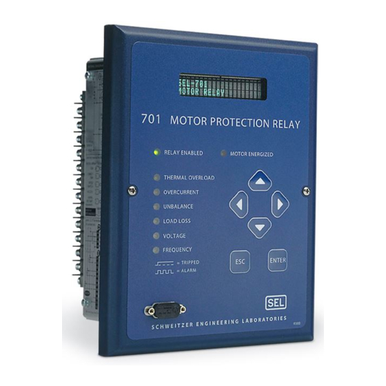
Motor Protection Relay
Brand:
Schweitzer Engineering Laboratories
| Category:
Relays
| Size: 4.04 MB
Table of Contents
Table of Contents
3
List of Tables
7
List of Figures
13
Introduction
17
List of Examples
19
Manual Change Information
21
Section 1: Introduction & Specifications
23
Introduction
23
Typographic Conventions
25
Table 1.1
25
SEL-701 Relay Models
26
Table 1.2
26
Figure 1.1 SEL-701 Relay Functional Description
26
SEL-701 Relay Applications
27
Figure 1.2 SEL-701 Relay Applications
27
SEL-701 Relay Protection Features
28
SEL-701 Relay Monitoring & Reporting Features
29
Relay Part Number
30
SEL-701 Relay Part Number Creation Table
30
SEL-701 Relay Serial Number Label
32
Figure 1.3 SEL-701 Relay Serial Number Label
32
Specifications
33
Section 2: Installation
37
Panel Cut & Drill Plans
37
Figure 2.1 SEL-701 Relay
38
Section 2: Installation
39
Figure 2.2 SEL-701 Relay Cut and Drill Dimensions
39
Relay Mounting
40
Figure 2.3 SEL-701 Relay Panel Mounting Detail
40
Relay Rear-Panel Diagram
41
Figure 2.4 SEL-701 Relay Rear Panel
41
Figure 2.5 SEL-701 Relay Left- and Right-Side Panel Drawings
42
Example AC Wiring Diagrams
43
Figure 2.6 Example AC Wiring Diagram, Four-Wire Wye Voltages and Ground
43
Figure 2.7 Example AC Wiring Diagram, Open-Delta Voltages and Residual in Connection
44
Figure 2.8 Example AC Voltage Wiring Diagram, Single Phase-To-Phase Voltage
45
Figure 2.9 Example AC Voltage Wiring Diagram, Single Phase-To-Neutral Voltage
45
Relay Connections
46
Figure 2.10 Ground CT Placement
48
Figure 2.11 Contact Output Factory Default Wiring Diagram
50
Figure 2.12 Trip Contact Fail-Safe, Nonfail-Safe Wiring Options
51
Figure 2.13 Optional Motor Start Wiring Using Factory Default Settings for Output Contact OUT3
52
Figure 2.14 Contact Input Factory Default Wiring Diagram
53
Figure 2.15 Analog Output Wiring
54
Table 2.1
55
Typical Maximum RTD Lead Lengths
55
Figure 2.16 RTD Input Wiring
56
SEL-2600 RTD Module
60
Section 3: SEL-701PC Software
61
Introduction
61
System Requirements
62
Table
62
SEL-701PC Software System Requirements
62
Installation
63
Section 4: Settings Calculation
65
Introduction
65
Application Data
67
General Data
68
Identifier Settings
68
Table 4.1
68
CT Configuration Settings
68
Figure 4.1 Phase Rotation Settings
69
Phase Rotation, Nominal Frequency Settings
69
Table 4.3
69
Table 4.4
70
VT Configuration Settings
70
Basic Motor Protection
72
Table 4.5
73
Thermal Element Configuration Settings, Setting Method = RATING
73
Table 4.6
75
Thermal Element Configuration Settings, Setting Method = GENERIC
75
Figure 4.2 Generic Thermal Limit Curves, Cold Motor
77
Figure 4.3 3000 HP Example Motor Cold Thermal Limit Curve
83
Figure 4.4 Ground Fault Currents Using a Window
88
RTD-Based Protection
94
Table 4.23 RTD Location Settings
95
Table 4.24 RTD Type Settings
96
Table 4.25 RTD Alarm and Trip Temperature Settings
97
Table 4.26 RTD Resistance Versus Temperature
100
Voltage-Based Protection (Relay Models 0701001X & 0701011X)
101
Table 4.28 Under- and Overvoltage Settings, Phase-To-Neutral Potentials
102
Table 4.30 Underpower Element Settings
103
Table 4.31 Power Factor Element Settings
104
Table 4.32 Frequency Element Settings
105
Output Configuration
106
Table 4.34 Front-Panel Configuration Settings
107
Table 4.35 Display Message Settings
108
Table 4.36 Output Contact Fail-Safe Trip Duration, and Starting Lockout Settings
109
Table 4.38 Factory Logic Settings
110
Figure 4.5 Factory Tripping Logic
111
Figure 4.6 Factory Contact Output Logic
112
Figure 4.7 Factory Contact Input Logic
112
Figure 4.8 Factory Event Triggering Logic
113
Serial Port Settings
114
Table 4.40 SET P Rear-Panel Serial Port Settings, Protocol = MOD
115
Sequential Events Recorder (SER) Settings
116
Table 4.42 Default SER Trigger Setting Relay Word Bits Definitions
117
Table 4.43 SET R SER Enable Alias Settings
119
Table 4.44 SET R SER Alias Settings
120
Section 5: Front-Panel Operation
121
Front-Panel Layout
121
Figure 5.1 SEL-701 Relay Front Panel
121
Normal Front-Panel Display
122
Figure 5.2 Default Meter Display Screen
122
Figure 5.3 Default Display Message Screen
122
Front-Panel Automatic Messages
123
Table 5.1
123
Front-Panel Menus & Operations
124
Figure 5.4 Front-Panel Pushbuttons
124
Figure 5.5 Access Level Security Padlock Symbol
125
Front-Panel Pushbutton Functions
125
Table 5.2
125
Figure 5.6 Password Entry Screen
126
Front-Panel Main Menu
128
Figure 5.7 Activate Front-Panel Display
128
Figure 5.8 Front-Panel Main Menu
128
Figure 5.9 Main Menu: Start Motor Function
129
Figure 5.10 Main Menu: Emergency Restart Function
129
Figure 5.11 Main Menu: Stop Motor Function
129
Figure 5.12 Main Menu: Reset Trip/Targets Function
130
Figure 5.13 Main Menu: Set Relay Function
130
Figure 5.14 Set Relay\Relay Elements Function
131
Figure 5.15 Set Relay\Ser Setting Categories
132
Figure 5.16 Set Relay\Front Serial Port Settings
133
Figure 5.17 Set Relay\Rear Serial Port Settings
134
Figure 5.18 Set Relay\Date Function
134
Figure 5.19 Set Relay\Time Function
135
Figure 5.20 Set Relay\Password Function
135
Figure 5.21 Main Menu: Meter Values Function
136
Figure 5.22 Meter Values Display Functions
136
Figure 5.23 Meter Values Reset Functions
137
Figure 5.24 Main Menu: History Data Function
137
Figure 5.25 History Data\Display History Function
137
Figure 5.26 History Data\Clear History Function
138
Figure 5.27 Main Menu: Motor Statistics Function
138
Figure 5.28 Motor Statistics\Motor Use Data Function
138
Figure 5.29 Motor Statistics\Average and Peak Data Function
139
Figure 5.30 Motor Statistics\Trip and Alarm Data Function
139
Figure 5.31 Motor Statistics\Reset Statistics Function
140
Figure 5.32 Main Menu: Status of Relay Function
140
Figure 5.33 Main Menu: View Relay Word Function
141
Figure 5.34 Main Menu: Pulse out Contact Function
141
Figure 5.35 Pulse Output Contact Menu Function
141
Figure 5.36 Main Menu: Reset Thermal Model Function
142
Figure 5.37 Main Menu: Reset Learned Param Function
142
Figure 5.38 Reset Learned Param\Reset Cooling Time Function
142
Figure 5.39 Reset Learned Param\Reset Start Therm Cap Function
143
Section 6: ASCII Serial Port Operation
145
Introduction
145
You will Need
146
Connect Your PC to the Relay
147
Figure 6.1 Cable C234A Pinout
147
Figure 6.2 DB-9 Connector Pinout for EIA-232 Serial Ports
147
Pin Functions and Definitions for SEL-701 Relay EIA-232 Serial Ports
148
Table 6.1
148
Configure Your Terminal Emulation Software
149
SEL-701 Relay Serial Communication Default Settings
149
Table 6.2
149
Using Terminal Commands
150
Table 6.3
150
Serial Port Access Levels
151
Command Summary
152
SEL-701 Serial Port Command Summary
152
Table 6.4
152
Command Explanations
154
Figure 6.3 HELP Command Response
154
Figure 6.4 2AC Command Example
155
Figure 6.5 ANA Command Example
155
Table
156
SEL-701 Relay Control Subcommands
156
Table 6.5 SEL-701 Relay Control Subcommands
156
Table 6.6
157
Event Commands
157
EVE Command Examples
157
Figure 6.6 DATE Command Example
157
Figure 6.7 HISTORY Command Example
158
LDP Command Options
158
Table 6.8
158
Figure 6.8 METER Command Example
160
Figure 6.9 METER D Command Example
160
Figure 6.10 METER E Command Example
161
Figure 6.11 METER M Command Example
161
Figure 6.12 METER T Command Example
162
MSR General Command Format
163
Table 6.9
163
Table 6.10 PULSE Command Format
164
Figure 6.13 PULSE Command Example
165
Figure 6.14 RLP Command Example
165
Table 6.11 SER Command Options
166
Table 6.13 SET Command Editing Keystrokes
167
Table 6.15 SHOW Command Options
168
Figure 6.15 SHOW Command Example
169
Table 6.16 STATUS Command Options
170
Figure 6.16 STATUS Command Example
171
Figure 6.17 TARGET Command Example
172
Table 6.17 TARGET Command Options
172
Figure 6.18 TIME Command Example
174
Table 6.19 SEL-701 Relay Word & Corresponding TAR Command
174
Figure 6.19 TRIGGER Command Example
175
Serial Port Automatic Messages
176
Section 7: Commissioning
177
Introduction
177
Relay Commissioning Procedure
178
Figure 7.1 Three-Phase AC Connection Test Signals
180
Figure 7.2 Open-Delta AC Potential Connection Test Signals
181
Serial Port Commands that Clear Relay Data Buffers
182
Table 7.1
182
Selected Functional Tests
184
Figure 7.3 Three Voltage Source and Three Current Source Test Connections
184
Figure 7.4 Two Voltage Source and Three Current Source Test Connections
184
Table 7.2
184
Test Source Connections for Different Relay Configurations
184
Phase Current Measuring Accuracy
187
Table 7.3
187
Neutral Current Measuring Accuracy
188
Table 7.4
188
Current Unbalance Measuring Accuracy
189
Table 7.5
189
Table 7.6
190
Thermal Element Expected Trip Times
190
Analog Output Test
191
Table 7.7
191
100-Ohm Platinum RTD Type (Rtds 1-6)
192
Table 7.8
192
100-Ohm Platinum RTD Type (Rtds 7-12)
192
Table 7.10 120-Ohm Nickel RTD Type (Rtds 1–6)
193
Table 7.12 100-Ohm Nickel RTD Type (Rtds 1–6)
194
Table 7.14 10-Ohm Copper RTD Type (Rtds 1–6)
195
Table 7.16 Power Measuring Accuracy Test Values, Wye Voltages
196
Table 7.17 Power Measuring Accuracy Test Values, Delta Voltages
197
Section 8: Metering & Monitoring
199
Introduction
199
Measured Values
200
Table 8.1
200
Demand Meter Values
201
Table 8.2
201
Max/Min Recorded Values
201
Table 8.4
202
Thermal Meter Values
202
RTD Input Status Messages
203
Table 8.5
203
Energy Meter Values
203
Power Measurement Conventions
204
Figure 8.1 Power Measurement Conventions
204
Load Profiling
205
Load Profile Values
205
Table 8.7
205
Figure 8.2 LDP Command Response
206
Motor Operating Statistics
207
Figure 8.3 MOTOR Command Example
209
Motor Start Report
210
Figure 8.4 Motor Start Report Example
211
Motor Start Trending
212
Figure 8.5 Motor Start Trending Report Example
212
Section 9: Event Analysis
213
Introduction
213
Front-Panel Target Leds
214
SEL-701 Relay Front-Panel Target LED Definitions
214
Table 9.1
214
Front-Panel Messages
216
History Data & Event Summaries
217
Event Reports
219
Event Commands
220
Table 9.2
220
EVE Command Options
220
Event Report Current and Voltage Columns
221
Table 9.4
221
Output, Input, and Element Event Report Columns
222
Table 9.5
222
Table 9.5
223
Sequential Events Recorder (SER) Report
225
Retrieving SER Reports
225
Table 9.6
225
Example Event Report
228
Figure 9.1 Example Event Report
229
Example Sequential Events Recorder (SER) Report
230
Figure 9.2 Example Sequential Events Recorder (SER) Event Report
230
Table 9.7 Example Sequential Events Recorder (SER) Report Explanations
231
Section 10: Maintenance & Troubleshooting
233
Routine Maintenance Checks
233
Table 10.1 Data Capture
234
Self-Testing
235
Troubleshooting Procedure
238
Table 10.6 Relay Does Not Respond to Command from Device Connected to Serial Port
239
Power Supply Fuse Replacement
240
Real-Time Clock Battery Replacement
241
Firmware Upgrade Installation
242
Factory Assistance
245
Table A.1 SEL-701 Relay Firmware Versions
247
Appendix A Firmware Versions
247
Ogic
247
Appendix B: SEL OGIC Control Equations & Relay Logic
249
Introduction
249
Relay Functional Overview
250
Relay Word Bits
252
Table B.2 Relay Word Bit Definitions for SEL-701
253
SEL OGIC Control Equations
257
Figure B.2 Result of Falling-Edge Operator on a Deasserting Underfrequency Element
258
Factory Default Logic Settings
261
Front-Panel Display Message Configuration
263
Nondedicated SEL OGIC Control Equation Variable Settings
264
Figure B.3 SEL OGIC Control Equation Variable Timer Logic
264
Latch Control Switch Settings
265
Figure B.4 Traditional Latching Relay
265
Figure B.5 Latch Control Switches Drive Latch Bits LT1 through LT4
265
Stop/Trip Logic
267
Breaker Auxiliary Contact SEL OGIC Control Equation Setting
270
Start and Emergency Restart Logic
271
Figure B.7 Start Logic
271
ACCESS2 SEL OGIC Control Equation Setting
273
TARR SEL OGIC Control Equation Setting
274
Speed Switch SEL OGIC Control Equation Setting
275
Event Triggering SEL OGIC Control Equation
276
Contact Output Control
277
Remote Control Switches
278
Figure B.8 Remote Control Switches Drive Remote Bits RB1 through RB4
278
Selected Relay Logic Diagrams
280
Figure B.9 Undervoltage Element Logic
280
Figure B.10 Underpower Element Logic
280
Figure B.12 Phase Reversal Element Logic
282
Figure B.13 Overcurrent Element Logic
283
Figure B.14 Power Factor Elements Logic
284
Figure B.15 Overvoltage Element Logic
285
Figure B.17 Load-Jam Elements Logic
288
Figure B.18 Load-Loss Logic; no Voltage Option
288
Figure B.19 Load-Loss Logic; Voltage Option Included
289
Figure B.20 Reactive Power Elements Logic
290
Figure B.21 Speed Switch Tripping Logic
290
Appendix C: Modbus
291
RTU Communications Protocol
291
Introduction
291
Modbus RTU Communications Protocol
291
Table C.2 SEL-701 Relay Modbus Function Codes
293
01H Read Coil Status Command
295
02H Read Input Status Command
296
03H Read Holding Registers Command
297
04H Read Input Registers Command
298
05H Force Single Coil Command
299
06H Preset Single Register Command
300
07H Read Exception Status Command
301
08H Loopback Diagnostic Command
302
10H Preset Multiple Registers Command
303
Controlling Output Contacts & Remote Bits Using Modbus
304
Table C.15 Modbus Command Codes
305
Reading the Relay Status Using Modbus
306
User-Defined Modbus Data Region
307
Reading Event Data Using Modbus
308
Table C.17 Assign Event Report Channel Using Address 0392H
308
Modbus Register Map
309
Table C.18 Modbus Register Map
309
Appendix Dsel-2020/2030 & SEL-701PC Compatibility Features
347
Introduction
347
Fast Binary Message Lists
348
Fast Binary Message Definitions
349
Table D.4 A5C1 Fast Meter Configuration Block
350
Table D.5 A5D1 Fast Meter Data Block
355
Demand Fast Meter Configuration Messages
356
Table D.7 A5D2/A5D3 Demand/Peak Demand Fast Meter Message
359
Table D.8 A5CE Fast Operate Configuration Block
360
Table D.9 A5E0 Command
362
Table D.10 A5E3 Command
363
Compressed ASCII Commands
365
CASCII Command
366
CSTATUS Command
370
CHISTORY Command
371
CEVENT Command
372
CME E Command
374
CME M Command
375
CME T Command XXXXXX
376
Appendix E Motor Thermal Element
377
Introduction
377
Purpose of Motor Thermal Protection
379
Figure E.1 Motor Thermal Limit Characteristic Plotted with Motor Starting Current
380
The Basic Thermal Element
381
Figure E.2 Electrical Analog of a Thermal System
381
Figure E.3 Typical Induction Motor Current, Torque, and Rotor Resistance Versus Slip
382
Motor Starting Protection
384
Figure E.4 Motor Starting Thermal Element
384
Motor Running Protection
385
Figure E.5 Motor Running Thermal Element with Resistance and Trip Level Undefined
385
Figure E.6 Calculating the Normal Operating Energy Using Locked Rotor Trip Times
385
Figure E.7 Motor Running Thermal Element
386
Interpreting Percent Thermal Element Capacity Values
388
Motor Starting Thermal Capacity
389
Appendix F: SEL-701 Relay Settings Sheets
443
Glossary
443
Index
453
Advertisement
Advertisement
Related Products
Schweitzer Engineering Laboratories SEL-700G Series
Schweitzer Engineering Laboratories SEL-700G0
Schweitzer Engineering Laboratories SEL-700G1
Schweitzer Engineering Laboratories SEL-700GT
Schweitzer Engineering Laboratories SEL-700GW
Schweitzer Engineering Laboratories SEL-751
Schweitzer Engineering Laboratories SEL-787-3
Schweitzer Engineering Laboratories SEL-787-4
Schweitzer Engineering Laboratories SEL-787-2X
Schweitzer Engineering Laboratories SEL-787-21
Schweitzer Engineering Laboratories Categories
Relays
Computer Hardware
Transceiver
Protection Device
Measuring Instruments
More Schweitzer Engineering Laboratories Manuals
Login
Sign In
OR
Sign in with Facebook
Sign in with Google
Upload manual
Upload from disk
Upload from URL