Mitsubishi Electric AE-200A Installation Manual
Air conditioning control system centralized controller
Hide thumbs
Also See for AE-200A:
- Instruction book (192 pages) ,
- Service handbook (108 pages) ,
- Installation manual (40 pages)
Table of Contents
Advertisement
Quick Links
Air Conditioning Control System
Centralized Controller
AE-200A/AE-50A
AE-200E/AE-50E
or
CAUTION, depending on the severity
of possible consequences that may result
when the instructions are not followed
exactly as stated.
Proper installation is important for your
safety and proper functioning of the units.
Thoroughly read the following safety
precautions prior to installation.
Before installing the controller, please read this Installation Manual carefully to ensure proper operation.
Retain this manual for future reference.
Contents
1. Safety precautions ..................................................... 2
1-1. General precautions ..............................................................2
1-2. Precautions for unit installation .............................................3
1-3. Precautions for electrical wiring ............................................3
1-4. Precautions for relocating or repairing the unit .....................4
1-5. Additional precautions ...........................................................4
2. Introduction ................................................................ 6
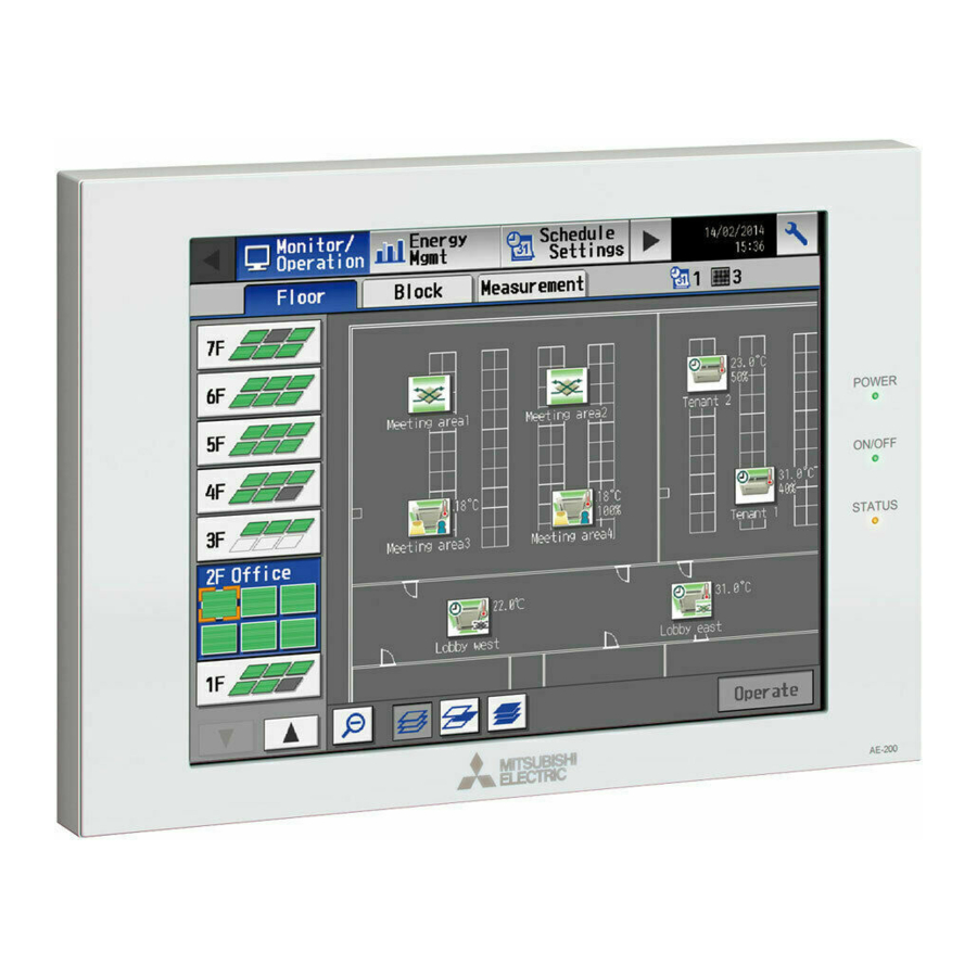
2-1. Part names ............................................................................7
3. Package contents ....................................................... 9
4. Specifications ........................................................... 10
4-1. Product specifications .........................................................10
4-2. External dimensions ............................................................ 11
5. Installation ................................................................ 12
5-1. Installation methods ............................................................12
5-2. Items not included ...............................................................13
5-3. Items sold separately ..........................................................14
5-4. Installation space ................................................................14
5-5. Installation procedures ........................................................14
6. Wiring connections ................................................... 17
6-1. Removing/reinstalling the service cover ..............................17
cables ..................................................................................18
6-3. Connecting the LAN cable ..................................................20
6-4. Confirming the LAN transmission delay time ......................20
7. Initial settings ........................................................... 22
8. Test run .................................................................... 24
8-1. Collective operation ON/OFF ..............................................24
9. External input/output ................................................ 25
9-1. External signal input/output function ...................................25
9-2. Pulse signal input function ..................................................27
10. Maintenance ............................................................. 28
10-1. Inspection and maintenance .............................................28
10-2. Software update ................................................................29
10-3. Software information .........................................................34
<ORIGINAL>
Installation Manual
Advertisement
Table of Contents

Related Manuals for Mitsubishi Electric AE-200A


Summary of Contents for Mitsubishi Electric AE-200A
-
Page 1: Table Of Contents
<ORIGINAL> Air Conditioning Control System Centralized Controller AE-200A/AE-50A AE-200E/AE-50E Installation Manual Contents 1. Safety precautions ............. 2 1-1. General precautions ..............2 1-2. Precautions for unit installation ..........3 1-3. Precautions for electrical wiring ..........3 1-4. Precautions for relocating or repairing the unit .....4 1-5. -
Page 2: Safety Precautions
1. Safety precautions Thoroughly read the following safety precautions prior to installation. Observe these precautions carefully to ensure safety. After reading this manual, pass the manual on to the end user to retain for future reference. The user should keep this manual for future reference and refer to it as necessary. This manual should be made available to those who repair or relocate the units. -
Page 3: Precautions For Unit Installation
To reduce the risk of fire or explosion, do not place flammable materials or use flammable sprays around the controller. To reduce the risk of electric shock or malfunction, do not touch the touch panel, switches, or buttons with a sharp object. To avoid injury from broken glass, do not apply excessive force to the glass parts. -
Page 4: Precautions For Relocating Or Repairing The Unit
Electrical work must be performed by qualified personnel in accordance with local regulations and the instructions provided in this manual. Only use specified cables and dedicated circuits. Inadequate power source capacity or improper electrical work will result in electric shock, malfunction, or fire. To reduce the risk of electric shock, install an overcurrent breaker and an earth leakage breaker on the power supply. - Page 5 Take appropriate measures against electrical noise interference when installing the controller in hospitals or radio communication facilities. Inverter, high-frequency medical, or wireless communication equipment as well as power generators may cause the air conditioning system to malfunction. The air conditioning system may also adversely affect the operation of these types of equipment by creating electrical noise.
-
Page 6: Introduction
Peak Cut control can be performed without a use of a PI controller (PAC-YG60MCA). Each AE-200A/AE-50A/AE-200E/AE-50E can control up to a total of 50 indoor units and other equipment. By connecting AE-200A/AE-200E (main controller) and AE-50A/AE-50E/EW-50A/EW-50E (expansion controllers), up to 200 indoor units and other equipment can be controlled. -
Page 7: Part Names
2-1. Part names Power LINK/ACT1 ON/OFF USB port LINK/ACT2 Status Push switch Display/Touch panel Item Description Lit in green Power ON Power Unlit Power OFF Lit in green One or more air conditioning units are ON. One or more air conditioning units or other related equipment ON/OFF Blink in green are in error. - Page 8 * Back side with the service cover removed L/L1 N/L2 LAN1 LAN2 Ground CN21 Item Description LAN1 Connects to other units of equipment over the LAN via a HUB. ® Connects to the Building Management System over the LAN (BACnet ) via a LAN2 HUB.
-
Page 9: Package Contents
3. Package contents The following items are included in the package. Package contents Qty. Centralized controller (AE-200 or AE-50) * A screw is attached at the bottom. Connector (CN6) (Unused) Connector (CN7) (Used for pulse input) Plate A Plate B *1, 2 Countersunk screw (M4 ×... -
Page 10: Specifications
4. Specifications 4-1. Product specifications Item Specifications Power supply Rated input 100–240 VAC ± 10%; 0.3–0.2 A 50/60 Hz Single-phase M-NET power feeding coefficient 0.75 Network interface 100BASE-TX Operating temperature 0°C – +40°C (+32°F – +104°F) range Temperature Ambient Storage temperature conditions -20°C –... -
Page 11: External Dimensions
4-2. External dimensions * The dimensions of AE-200 and AE-50 are the same. Unit: mm (in) 284 (11-5/32) 25 (31/32) 40 (1-9/16) Screw: M4 × 6 Hexagonal hole: 2.5 (width across flat) 246 (9-11/16) 261.2 (10-9/32) 217 (8-35/64) 272.7 (10-47/64) 282.7 (11-1/8) 261.2 (10-9/32) 261.2 (10-9/32) -
Page 12: Installation
5. Installation To reduce the risk of injury or electric shock, switch off the main power before performing electrical work. To avoid malfunction, do not bundle power cables and signal cables together or place them in the same metallic conduit. 5-1. -
Page 13: Items Not Included
5-2. Items not included The following items are required to install the AE-200/AE-50. Items not included Specifications Electrical box (required only for installation Model: PAC-YG84UTB-J method 2) Metal control box Must be suitable for the AE-200/AE-50 installation. (required only for installation Minimum metal thickness when using installation method 4: 200 mm (7-7/8 in) methods 3 and 4) Locknuts and bushing... -
Page 14: Items Sold Separately
5-3. Items sold separately Items sold separately Model name Remarks Electrical box PAC-YG84UTB-J Required only for installation method 2 L-fittings Mounting kit PAC-YG86TK-J Required only for installation method 4 DIN rail attachments Mounting Attachment PAC-YG82TB-J Required only for installation method 5 Surface cover with USB port PAC-YG72CWL-J Required when using a cover with USB port... - Page 15 5-5-1. Cutting an installation hole and mounting holes in the wall (Methods 1 and 2) Cut an installation hole (169 × 252 mm (6-21/32 × 9-59/64 in)) and mounting holes in the wall as shown in the figure below. Unit: mm (in) 252 (9-59/64) 217 (8-35/64) ø6 (ø15/64)
- Page 16 5-5-3. Wall-embedded installation with an electrical box (Method 2) Conduit tube Wall Locknut Wire access hole Bushing Electrical box Seal the gap with putty. M-NET transmission cable or AC power cable * Adjust the cable length so that they will fit in the electrical box.
-
Page 17: Wiring Connections
6. Wiring connections 6-1. Removing/reinstalling the service cover Unscrew the fixing screw on the service cover and unhook the hooks to remove it as shown in the figure below. To replace the service cover, hook the hooks and screw the fixing screw back in. Note When routing the cables from the bottom, cut out the knockout holes, cut a slit in the supplied rubber bushings to insert the cables without the gap, and attach the bushings to the knockout holes. -
Page 18: Connecting Ac Power Cables And M-Net Transmission Cables
6-2. Connecting AC power cables and M-NET transmission cables AE-200/AE-50 Outdoor unit Overcurrent breaker M-NET transmission cables Earth leakage breaker for centralized control 100–240 VAC AC power cables 6-2-1. AC power cables and protective ground wire 1. Attach M3.5 sleeved ring terminals to the AC power cables, and attach an M4.0 sleeved ring terminal to the protective ground wire. - Page 19 6-2-2. M-NET transmission cables (Centralized control transmission cables) 1. Attach M3.5 sleeved ring terminals to the M-NET transmission cables (A, B, Shield). 2. Connect the M-NET transmission cables to the M-NET terminal block. 3. Fix the cables in place with the supplied cable tie. 4.
-
Page 20: Connecting The Lan Cable
6-3. Connecting the LAN cable ® Connect the LAN cable to the LAN1 port on the AE-200/AE-50. (The LAN2 port is exclusively used for BACnet function.) The LAN cable is not supplied. Use a category 5 or above straight LAN cable. Use a switching HUB compatible with 100 BASE. - Page 21 [2] Checking the transmission delay time ① Click [Start]>[Program]>[Accessories]>[Command Prompt] on the monitoring PC. * The procedure may vary depending on the OS. ② Enter [ping (IP address of AE-200/AE-50/EW-50)], and press the Enter key. ([ping -w 4000 192.168.1.1] is entered on the sample screen below.) ③...
-
Page 22: Initial Settings
7. Initial settings Initial settings need to be made for each AE-200 on the AE-200’s LCD, Initial Setting Tool, or the Web browser. The table below explains how to make initial settings on the AE-200’s LCD. Details about the initial settings are covered in the AE-200 Instruction Book (Initial Settings). - Page 23 System configuration Procedure Details ① ① Touch the [Groups] tab in the [Initial Settings] menu. ② Make group settings for AE-200, and touch [Save Settings]. Make sure that [AE200] is selected as [Controller], make group settings for AE-200, Group settings ②...
-
Page 24: Test Run
8. Test run 8-1. Collective operation ON/OFF Confirm that the group settings and interlock settings are complete before performing a test run. It may take approximately five minutes from power on until the local remote controllers become operable. Refer to the indoor unit Installation Manual for details about a test run. Test run procedure (1) Turn on the power to the AE-200 and all units. -
Page 25: External Input/Output
9. External input/output 9-1. External signal input/output function To reduce the risk of injury, do not touch the burrs of the knockout holes. To use external input/output, a separately-sold external input/output adapter (PAC-YG10HA-E) is required. When connecting an external input/output adapter (PAC-YG10HA-E), cut out the CN5 knockout hole. (Refer to section 2-1 “Part names”... - Page 26 9-1-2. External signal output function An ON signal is output when one or more units are in operation, and an Error signal is output when one or more units are in error. (1) Recommended circuit Relay-driven circuit Use relays Z1 and Z2 that meet the following specifications.
-
Page 27: Pulse Signal Input Function
9-2. Pulse signal input function Using pulse signals directly input from metering device such as watt-hour meter, billing data and energy management data will be obtained based on the cumulative number of pulse signal input. Note To input pulse signals directly from the metering device to the AE-200, use the connector connected to the AE-200. (A precision screwdriver for M1 screws is required.) Usability of a built-in PI controller for each function Function... -
Page 28: Maintenance
10. Maintenance 10-1. Inspection and maintenance Air conditioning units including AE-200/AE-50 controllers may be damaged after long use, resulting in a performance drop or the units becoming a safety hazard. To use them safely and maximize their lives, it is recommended that a maintenance contract with a dealer or qualified personnel be signed. -
Page 29: Software Update
10-2. Software update Update AE-200/AE-50 software. Prepare the update file so that all versions are standardized, without needing to load a previous software version. The AE-200/AE-50 software can be updated by either directly reading the update file in a USB memory device or by using a Web browser. - Page 30 10-2-1. Directly reading the update file in a USB memory device [1] Preparation Store the update file (AExx_FW####_****.dat) in the root folder of a USB memory device. *1 “xx”: “200” (AE-200) or “50” (AE-50); “####”: software version [2] Update procedures Note: The software cannot be downgraded to an earlier version.
- Page 31 (7) Touch [ ] to display the login window. Check that the version on the login window is the same as the version of the update file (AExx_FW####_****.dat). * If the name of the update file contains ####, “Ver. #.##” should be displayed on the login window as shown at right.
- Page 32 Click [Continue to this website (not recommended)]. (5) Enter the maintenance user name and the password in the login screen, and click [OK]. (Default user name: initial, Default password: init) (6) A software update screen will appear. AE-200A #.##(*.**) xxxxxx WT07935X04...
- Page 33 FW####_****.dat) stored in the USB memory device, and click [Start Update]. AExx_FW####_****.dat Note: The software cannot be downgraded to an earlier version. Note: “####” indicates the software version. AE-200A 7.60(1.07) #.##(*.**) xxxxxx (8) A software update process starts. Note: It takes about ten minutes to complete the update.
-
Page 34: Software Information
If the software update did not properly complete, update the software again. If the problem persists, the AE-200/AE-50 may be damaged. Consult your dealer. 10-3. Software information Detailed information about the open source software of the AE-200/AE-50/EW-50 can be checked by accessing the following address: https://[IP address of each AE-200, AE-50, or EW-50]/license/ * Accessible only if logged in as a maintenance user. - Page 35 SD and SDHC Logos are trademarks of SD-3C, LLC. Java is a registered trademark of Oracle and/or its affiliates. BACnet ® is a registered trademark of ASHRAE (American Society of Heating, Refrigerating and Air-Conditioning Engineers, INC.). This equipment has been tested and found to comply with the limits for a Class B digital device, pursuant to Part 15 of the FCC Rules.
- Page 36 Please be sure to put the contact address/telephone number on this manual before handing it to the customer. HEAD OFFICE: TOKYO BLDG., 2-7-3, MARUNOUCHI, CHIYODA-KU, TOKYO 100-8310, JAPAN MANUFACTURER: MITSUBISHI ELECTRIC CORPORATION Air-conditioning & Refrigeration Systems Works 5-66, Tebira 6 Chome, Wakayama-city, 640-8686, Japan WT07935X04...