
Related Manuals for microHAM DXP


Summary of Contents for microHAM DXP
- Page 1 © 2019 All rights reserved microHAM www.microham.com Version 1.0 2019...
-
Page 2: Table Of Contents
© 2019 All rights reserved TABLE OF CONTENT 1 - FEATURES AND FUNCTIONS ............................3 2 - PANEL DESCRIPTION ............................... 4 Front Panel ..................................4 Rear Panel ..................................5 3 - HARDWARE INSTALLATION Cables Connection and Initial Setup ............................ 6 Display Description and Basic Operation ........................ -
Page 3: Features And Functions
The relay-free construction of DXP provides quiet operation based on an optoMOS part replacing the traditional output relay. CAT interface is jumper-free set up from the menu. The DB15F system connector is fully compatible with previous microHAM interfaces: USB II, USB III, DK, and DK II and uses the same DB15 cables. -
Page 4: Panel Description
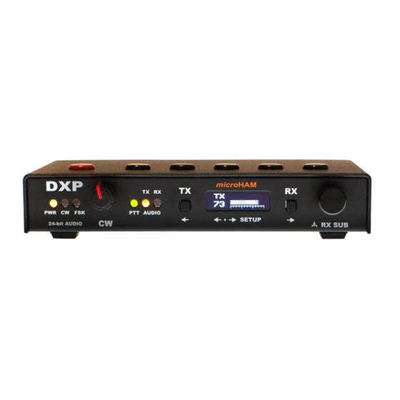
© 2019 All rights reserved 2 - PANEL DESCRIPTION Front Panel 1. PWR POWER LED lights when USB power is applied. Flashing in Stand-by. 2. CW LED flashes with CW output. 3. FSK LED flashes with FSK output. 4. SPEED CW speed control. -
Page 5: Rear Panel
© 2019 All rights reserved Rear Panel 1. RADIO DB15F connector for radio connection. See Appendix A for details 2. KEYBOAD USB A connector connecting external USB keyboard or thumb drive for firmware updates. 3. COMPUTER USB B connector for computer connection. Uses standard USB A-B cable. -
Page 6: Hardware Installation Cables Connection And Initial Setup
1. Turn off the radio and make the rear panel of the DXP accessible. 2. Plug the DB15M of the radio cable set into the RADIO connector on the rear panel of the DXP. Connect ALL connectors from the cable set to the matching jacks of your transceiver. -
Page 7: Display Description And Basic Operation
The CLIP sign on the top right corner of the display indicates that the level of signal into the DXP is too high. If you see this sign, you need to decrease the receive audio output signal level in your transceiver menu. -
Page 8: Software Installation
- they contain the appropriate driver but do not install it automatically. They will require an external definition file (INF file) for the device to be recognized. For DXP installation on Windows XP SP3 up to Windows 8.1, download the definition file (DXP.inf) from our web pages and follow the installation procedure described in Serial Ports chapter. -
Page 9: Serial Ports
This definition file can be downloaded from our website: http://www.microham.com/Downloads/DXP.inf When DXP is plugged in for the first time and the “New Hardware” window appears, select manual installation (Have Disk option) and direct the operating system to the path with the downloaded DXP.inf file. -
Page 10: Serial Ports Finder
CAT, FSK and WinKey port, you can install and run a simple application, DXP Ports Finder, which will list the DXP serial port assignments on your computer. The only purpose of this application is to identify the serial ports. It is not necessary to run it for normal operation, just to setup logger/digital mode software or troubleshooting. -
Page 11: Signals Configuration
DXP port for that function. CAT interface port in logger must be set to the port number or name of the CAT port in DXP; the FSK port in your RTTY program to the port number or name of the FSK port of DXP;... - Page 12 © 2019 All rights reserved Computer LEFT AUDIO IN MAIN DXP RX AUDIO ADC RIGHT AUDIO IN SUB LEFT AUDIO OUT AUDIO DAC RIGHT 2.1 QCW LEVEL DETECTOR 2.2 PFSK 1.1 CAT TYPE CAT DATA LEVEL CONVERTER 8.2 WK FSK...
-
Page 13: Setup Menu
The Setup Menu provides a very convenient way to configure the DXP interface functions without opening the DXP or using any computer program. Each menu item has a scrolling help on the display’s top line, thus you won't need to resort to the manual - AFTER you read the following chapter at least once :-)! To enter the Setup Menu press the TX and RX buttons at the same time. - Page 14 FS jack. If is set to PTTIN, DXP generates only PAPTT output during TX. PTT IS NOT sent to the radio in order to avoid “stuck in TX” effect. Input expects PTT (TX GND, SEND, Key Out, Remote, etc.) output from radio.
- Page 15 NO/YES • If set to YES, DXP redirects WinKey KEY port to FSK output of DXP instead of CW. It allows use of the new WinKey 3.1 FSK feature to send FSK from the chip in standalone mode. 9.1 Windows XP switches between asynchronous or synchronous mode of audio data output •...
-
Page 16: Keyboard
© 2019 All rights reserved Keyboard A standard USB keyboard can be connected to the USB-A connector on the back of DXP. Letters, typed on this keyboard, are played either as CW, or as FSK characters allowing to operate RTTY without computer with radio having built-in RTTY decoder e.g. -
Page 17: Cw Operation - Winkey
DXP for at least 5 seconds until WinKey indicates entering Standalone Mode by playing ‘MN’ prosign (dah-dah-dah-dit). The user can switch back to Host Mode by pressing and holding the rightmost button on top of DXP for at least 5 seconds, releasing the button when the display indicates so. -
Page 18: Firmware Update
DXP firmware is updated by loading it from an USB FLASH (“thumb”) drive: 1. Copy the update file dxp.upd to the root directory of a USB FLASH drive. Don’t place the update file to any subdirectory. Don’t rename the file. -
Page 19: Hardware Specifications
© 2019 All rights reserved 8 - HARDWARE SPECIFICATIONS USB: USB 2.0 Full speed, isolated CDC – serial ports UAC1 asynchronous/synchronous downstream, max. 24-bit/48kHz asynchronous upstream, 24-bit/48kHz Power consumption: USB – less than 250mA Radio Port: RxD, TxD – max. 115200 Baud... -
Page 20: Package Contents
SLOVAKIA 10 - WARRANTY microHAM warrants this product for two (2) years. The product must not be modified in any way or the warranty is voided. Cables are warranted against defects in materials and workmanship for a period of 60 days. -
Page 21: Declaration Of Conformity
© 2019 All rights reserved DECLARATION OF CONFORMITY Federal Communications Commission Statement (USA) This device complies with Part 15 of the FCC Rules. Operation is subject to the following two conditions: (1) this device may not cause harmful interference, and (2) this device must accept interference received, including interference that may cause undesired operation. -
Page 22: Appendix A - Db15 Transceiver Connector
© 2019 All rights reserved APPENDIX A – DB15 TRANSCEIVER CONNECTOR Pin # Label Description AUXPWR OUT 8V DC output, max. 1mA CAT IN Control port input CAT OUT Control port output Not connected Not connected PTT output "open collector"... -
Page 23: Appendix B - Rfi Considerations
It is absolutely important to prevent ground currents from flowing to the common ground point by way of the signal cable. If you use a microHAM "keyer," a good test is to remove the DB15/DB37 connector and USB cable from the keyer and measure the resistance from the shell of the DB15/DB37 to the shell of the USB cable.
Need help?
Do you have a question about the DXP and is the answer not in the manual?
Questions and answers