
Related Manuals for Siemens 6DR50 Series


Summary of Contents for Siemens 6DR50 Series
- Page 1 SIPART Electropneumatic positioners SIPART PS2 with and without HART Operating Instructions Edition 09/2014 Answers for industry.
- Page 3 ___________________ SIPART PS2 with and without HART Introduction ___________________ Safety information ___________________ SIPART Description ___________________ Installing/mounting Electropneumatic positioners SIPART PS2 with and without ___________________ HART Connection ___________________ Operating Operating Instructions ___________________ Commissioning ___________________ Functional safety ___________________ Parameterizing/addressing ___________________ Alarm, error, and system messages ___________________ Service and maintenance...
- Page 4 Note the following: WARNING Siemens products may only be used for the applications described in the catalog and in the relevant technical documentation. If products and components from other manufacturers are used, these must be recommended or approved by Siemens. Proper transport, storage, installation, assembly, commissioning, operation and maintenance are required to ensure that the products operate safely and without any problems.
-
Page 5: Table Of Contents
Table of contents Introduction ............................11 Purpose of this documentation ....................11 History ............................. 11 Purpose ........................... 12 Checking the consignment ..................... 12 Transportation and storage ..................... 13 Product information ......................... 13 Notes on warranty ........................13 Safety information ..........................15 Requirements for safe use ...................... - Page 6 Table of contents Using the positioner in a humid environment ................. 44 Positioners subjected to fast acceleration or strong vibration ..........45 External position detection ..................... 48 Installing option modules ....................... 48 4.7.1 General information on installing option modules ..............48 4.7.1.1 Installing optional modules in the standard and intrinsically safe version ......
- Page 7 Table of contents Commissioning ........................... 113 Basic safety instructions ....................... 113 Commissioning overview ...................... 115 Sequence of automatic initialization ..................117 Purge air switching ........................ 122 Commissioning linear actuators .................... 123 7.5.1 Preparing linear actuators for commissioning ..............123 7.5.2 Automatic initialization of linear actuators................
- Page 8 Table of contents 9.4.2.8 '35.YA' Start of manipulated variable limit / '36.YE' End of manipulated variable limit ..164 9.4.2.9 '37.YNRM' Standardization of manipulated variable............164 9.4.2.10 '38.YDIR' Direction of manipulated variable for display and position feedback ....166 9.4.2.11 '39.YCLS' Tight closing with manipulated variable ..............
- Page 9 Table of contents 10.2.3.14 Diagnostics parameter '16.ONLK' Pneumatic leakage ............213 10.2.3.15 Diagnostics parameter '17.STIC' Stiction (slipstick) ............. 214 10.2.3.16 Diagnostics parameter '18.ZERO' Lower endstop ..............214 10.2.3.17 Diagnostics parameter '19.OPEN' Displacement of upper end stop ........214 10.2.3.18 Diagnostics parameter '20.PAVG' Position average ............215 10.2.3.19 Diagnostics parameters '21.P0' Potentiometer value of bottom end stop / '22.P100' Potentiometer value of top end stop ..................
- Page 10 Table of contents 10.4.6 Remedial measures table 5 ....................234 Service and maintenance ........................235 11.1 Basic safety instructions ...................... 235 11.2 Cleaning of the screens ....................... 236 11.2.1 Positioners with Makrolon enclosure 6DR5..0, aluminum enclosure 6DR5..3, and flameproof aluminum enclosure 6DR5..5 ................236 11.2.2 Positioners with stainless steel enclosure 6DR5..2 and narrow aluminum enclosure 6DR5..1 ..........................
- Page 11 Table of contents 14.4 Scope of delivery of external position detection system ............270 14.5 Scope of delivery of mechanical limit switch module ............270 14.6 Scope of delivery EMC filter module ..................271 14.7 Accessories ........................... 272 Appendix............................. 273 Operation with boosters ......................
- Page 12 Table of contents SIPART PS2 with and without HART Operating Instructions, 09/2014, A5E00074631-12...
-
Page 13: Introduction
Introduction Purpose of this documentation These instructions contain all information required to commission and use the device. Read the instructions carefully prior to installation and commissioning. In order to use the device correctly, first review its principle of operation. The instructions are aimed at persons mechanically installing the device, connecting it electronically, configuring the parameters and commissioning it, as well as service and maintenance engineers. -
Page 14: Purpose
Introduction 1.3 Purpose See also Structure (Page 19) Construction (Page 243) Positioner with flameproof aluminum enclosure 6DR5..5 (Page 263) Purpose The electropneumatic positioner is used for the continuous control of process valves with pneumatic actuators in the following industries. ● Chemicals ●... -
Page 15: Transportation And Storage
The sales contract contains all obligations on the part of Siemens as well as the complete and solely applicable warranty conditions. Any statements regarding device versions described in the manual do not create new warranties or modify the existing warranty. - Page 16 Introduction 1.7 Notes on warranty SIPART PS2 with and without HART Operating Instructions, 09/2014, A5E00074631-12...
-
Page 17: Safety Information
Safety information Requirements for safe use This device left the factory in good working condition. In order to maintain this status and to ensure safe operation of the device, observe these instructions and all the specifications relevant to safety. Observe the information and symbols on the device. Do not remove any information or symbols from the device. -
Page 18: Laws And Directives
Further provisions for hazardous area applications are for example: ● IEC 60079-14 (international) ● EN 60079-14 (EC) See also Certificates (http://www.siemens.com/processinstrumentation/certificates) 2.1.3 Conformity with European directives The CE marking on the device shows conformity with the regulations of the following... -
Page 19: Requirements For Special Applications
Due to the large number of possible applications, each detail of the described device versions for each possible scenario during commissioning, operation, maintenance or operation in systems cannot be considered in the instructions. If you need additional information not covered by these instructions, contact your local Siemens office or company representative. Note... - Page 20 Safety information 2.4 Use in hazardous areas WARNING Loss of safety of device with type of protection "Intrinsic safety Ex i" If the device has already been operated in non-intrinsically safe circuits or the electrical specifications have not been observed, the safety of the device is no longer ensured for use in hazardous areas.
-
Page 21: Description
Description Function ● The electropneumatic positioner, in combination with the actuator, forms a control system. The current position of the actuator is detected using a potentiometer and returned as the actual value x. The setpoint and actual value are output simultaneously on the display. - Page 22 Description 3.2 Structure Various add-on extensions are available for linear actuators: ● IEC 60534-6-1 (NAMUR) ● Integrated addition to ARCA ● Integrated addition to SAMSON in non-flameproof aluminum enclosure ① Pressure gauge block, single-acting ② Valve ③ Yoke / actuator yoke ④...
- Page 23 Description 3.2 Structure ① Single-acting positioner in flameproof aluminum enclosure ② Pressure gauge block, single-acting ③ Yoke / actuator yoke ④ Actuator Figure 3-3 Positioner in flameproof aluminum enclosure attached to linear actuator ① Part-turn actuator ② Double-acting positioner in flameproof aluminum enclosure ③...
-
Page 24: Nameplate Layout
Description 3.2 Structure 3.2.2 Nameplate layout Layout of the nameplate ① ⑧ Manufacturer Software/hardware version ② ⑨ Safety class Place of manufacture ③ ⑩ Consult operating instructions Auxiliary power ④ ⑪ Conformity with country-specific directives Ordering supplement (Order code) ⑤ ⑫... - Page 25 Description 3.2 Structure Explanation of Ex information ① ④ Category for operating range Maximum surface temperature (tempera- ture class) ② ⑤ Type of protection Device protection level ③ Group (gas, dust) Figure 3-7 Explanation of Ex information SIPART PS2 with and without HART Operating Instructions, 09/2014, A5E00074631-12...
-
Page 26: Device Components
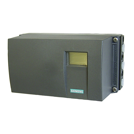
Description 3.3 Device components Device components 3.3.1 Overview of device components ① ⑩ Input: Supply air PZ Transmission ratio selector ② ⑪ Output: Actuating pressure Y1 Friction clutch adjustment wheel ③ ⑫ Display Basic electronics ④ ⑬ Output: Actuating pressure Y2 Connecting terminals of option modules ⑤... -
Page 27: Basic Electronics
Description 3.3 Device components ① ⑧ Input: Supply air PZ Restrictor Y2 ② ⑨ Output: Actuating pressure Y1 Friction clutch adjustment wheel ③ ⑩ Display Connecting terminals of option modules ④ ⑪ Output: Actuating pressure Y2 Connecting terminals of basic electronics ⑤... -
Page 28: Mode Of Operation
Description 3.4 Mode of operation ● Display ● Buttons ● Terminal strips to connect the option module to the basic electronics Mode of operation Control loop The electropneumatic positioner forms a control loop with the pneumatic actuator: ● The actual value x represents the position of the actuator spindle for linear actuators or the position of the actuator shaft for part-turn actuators. -
Page 29: Control Algorithm
Description 3.4 Mode of operation 3.4.1 Control algorithm The control algorithm is an adaptive, predictive five-point controller. In case of large control deviations, the valves are controlled using permanent contact. This takes place in the so-called fast step zone. In case of medium control deviations, valves are controlled using pulse-length modulated pulses. -
Page 30: Block Circuit Diagram For Single-Acting Or Double-Acting Actuators
Description 3.4 Mode of operation 3.4.2 Block circuit diagram for single-acting or double-acting actuators ① Basic electronics with microcontroller and input circuit ② Control pad with display and buttons ③ Single-acting or double-acting pneumatic block ④ Position feedback module for positioner ⑤... -
Page 31: Mode Of Operation Of The Hart Function
Description 3.4 Mode of operation 3.4.3 Mode of operation of the HART function Note Priority of operation / failure of power supply • Operation at the positioner has priority over specifications from the HART communicator. • Failure of the auxiliary power to the positioner also interrupts communications. Function The positioner is also available with built-in HART functionality. -
Page 32: Simatic Pdm
Description 3.4 Mode of operation System communication Communication is via the HART protocol, using: ● HART Communicator (load 230 ... 1100 Ω) ● PC with HART modem, on which appropriate software is installed, e.g. SIMATIC PDM (load 230 ... 500 Ω) ●... -
Page 33: Installing/Mounting
Installing/mounting Basic safety instructions WARNING Unsuitable device for the hazardous area Danger of explosion. • Only use equipment that is approved for use in the intended hazardous area and labelled accordingly. WARNING High operating force with pneumatic actuators Risk of injury when working on control valves due to the high operating force of the pneumatic actuator. - Page 34 Installing/mounting 4.1 Basic safety instructions WARNING It is possible to damage the cover gasket If the cover gasket is not positioned correctly in the groove of the base plate, it could be damaged when the cover is mounted and screwed tight. •...
- Page 35 Installing/mounting 4.1 Basic safety instructions CAUTION Please note the following before working on the control valve and when attaching the positioner Danger of injury. • Prior to working on the control valve, you must move the control valve into a completely pressureless state.
-
Page 36: Proper Mounting
Installing/mounting 4.2 Mounting the linear actuator 4.1.1 Proper mounting NOTICE Incorrect mounting The device can be damaged, destroyed, or its functionality impaired through improper mounting. • Before installing ensure there is no visible damage to the device. • Make sure that process connectors are clean, and suitable gaskets and glands are used. - Page 37 Installing/mounting 4.2 Mounting the linear actuator This section describes how to connect the positioner to the actuator using the mounting kit 6DR4004-8V. You require different installation parts of this mounting kit depending on the selected actuator type. All installation parts listed in the following table are included in the product package of the mounting kit 6DR4004-8V.
- Page 38 Installing/mounting 4.2 Mounting the linear actuator Procedure "Linear actuator IEC 60534 (3 to 35 mm)" mounting kit 6DR4004-8V and 6DR4004-8L Sr. No. Quantity Name Note ① NAMUR mounting bracket Standardized connection point for mount with fin, column or plane IEC 60534 surface ②...
- Page 39 Installing/mounting 4.2 Mounting the linear actuator ③ ⑯ 1. Install the clamping pieces on the actuator spindle. Use spring lock washers ⑰ socket cap screws for this purpose. ② ③ 2. Slide the pick-up bracket into the milled recesses of the clamping pieces Figure 4-1 Pick-up bracket 3.
- Page 40 Installing/mounting 4.2 Mounting the linear actuator ⑥ ⑰ 7. Install the following components on the lever : Socket cap screw , spring lock ⑯ ⑫ ⑲ washer , flat washer , square nut Figure 4-3 Components on the lever ⑥ 8.
- Page 41 Installing/mounting 4.2 Mounting the linear actuator Figure 4-5 Positioner in the flameproof enclosure, base plate 10.Select the row of holes. The selection of the row of holes depends on the yoke width of ④ the actuator. Select the row of holes in such a way that the carrier pin meshes with the ②...
-
Page 42: Mounting The Part-Turn Actuator
Installing/mounting 4.3 Mounting the part-turn actuator Mounting the part-turn actuator Requirements You require an actuator-specific VDI/VDE 3845 mount to install the positioner on a part-turn actuator. Procedure "Part-turn actuator" mounting kit 6DR4004–8D Name Note ① Coupling wheel Installation on positioner shaft ②... - Page 43 Installing/mounting 4.3 Mounting the part-turn actuator ⑥ 1. Rest the actuator-specific VDI/VDE 3845 mount on the rear side of the positioner. ⑦ ⑧ Tighten the mount using the hexagon bolts and lock washers ⑤ 2. Stick the pointer mark on the mount. Position the pointer mark at the center of the centering hole.
- Page 44 Installing/mounting 4.3 Mounting the part-turn actuator ② ② 4. Place the carrier on the stump of the actuator shaft. Tighten the carrier using the ⑨ ⑩ socket cap screw and the washer Figure 4-6 Carrier 5. With the coupling wheel: Place the positioner and the mount on the actuator carefully. ①...
- Page 45 Installing/mounting 4.3 Mounting the part-turn actuator ④ 10.Stick the scale with the direction of rotation or the swivel range on the coupling wheel ① . The stickers with scale are self-adhesive. Adhesive label with scale Adhesive label with scale, flameproof enclosure H = height of shaft butt ①...
-
Page 46: Using The Positioner In A Humid Environment
Installing/mounting 4.4 Using the positioner in a humid environment See also Preparing part-turn actuators for commissioning (Page 131) Using the positioner in a humid environment Introduction The positioner enclosure provides IP66 protection with an intended installation position. It can therefore be operated in a moist or wet environment in the mounting positions shown below. -
Page 47: Positioners Subjected To Fast Acceleration Or Strong Vibration
Installing/mounting 4.5 Positioners subjected to fast acceleration or strong vibration Procedure 1. Install the casing such that rain water or condensate running along the pipes can be drained before the terminal strip of the positioner. 2. Check the seals of electrical connections for perfect fitting. 3. - Page 48 Installing/mounting 4.5 Positioners subjected to fast acceleration or strong vibration Overview diagram NOTICE Wrong registration of the rotary or part-turn movement A different setting of the transmission ratio selector and the gear latch results in a hysteresis in position registration. The hysteresis in position registration can result in unstable control behavior of the higher level control loop.
- Page 49 Installing/mounting 4.5 Positioners subjected to fast acceleration or strong vibration Requirements ● The positioner is mounted. ● You know whether the transmission ratio is to be set to 33° or 90°. ● The positioner has been commissioned successfully, i.e. initialization was completed with "FINISH".
-
Page 50: External Position Detection
Installing/mounting 4.6 External position detection External position detection WARNING External position detection system Versions with flameproof enclosures may not be operated with an external position detection system. The aforementioned measures are not adequate in some applications. For example, continuous and strong vibrations, high or too low ambient temperatures and nuclear radiation. -
Page 51: Installing Optional Modules In The Standard And Intrinsically Safe Version
Installing/mounting 4.7 Installing option modules 4.7.1.1 Installing optional modules in the standard and intrinsically safe version The following option modules are available for the positioner in the standard and intrinsically safe version: ● Position feedback module ● Alarm module ● SIA module ●... - Page 52 Installing/mounting 4.7 Installing option modules Overview diagram: Installing optional modules in the standard and intrinsically safe version ① ⑪ Module cover Position feedback module ② ⑫ Fixing screws module cover Alarm module ③ ⑬ Fixing screws basic electronics Warning label on the side opposite the nameplate ④...
- Page 53 Installing/mounting 4.7 Installing option modules ⑧ ⑱ Friction clutch adjustment wheel Ribbon cable/connector for alarm mod- ule, SIA module or mechanical limit switch module ⑨ ⑲ Nameplate Ribbon cable/connector for position feedback module ⑩ ⑳ Adapter Wiring diagram Figure 4-10 Installing the optional modules in the standard and intrinsically safe version General procedure for optional modules in the standard and intrinsically safe version 1.
-
Page 54: Installing The Optional Modules In The "Flameproof Enclosure" Version
Installing/mounting 4.7 Installing option modules 4.7.1.2 Installing the optional modules in the "flameproof enclosure" version Introduction The following option modules are available for the positioner in the flameproof enclosure: ● Position feedback module ● Alarm module ● EMC filter module DANGER Risk of explosion You must fulfill the following conditions before supplying auxiliary power to the positioner in... - Page 55 Installing/mounting 4.7 Installing option modules Overview diagram: Installing the optional modules in the "flameproof enclosure" version ① ⑪ Module cover Transmission ratio selector ② ⑫ Fixing screws module cover Fixing screws adapter ③ ⑬ Ribbon cable/connector for fitted potentiometer or Safety catch external position detection system ④...
- Page 56 Installing/mounting 4.7 Installing option modules Figure 4-11 Installing the optional modules in the "flameproof enclosure" version General procedure for optional modules in the "flameproof enclosure" version 1. Disconnect the power supply lines or de-energize them. ⑬ 2. Open the safety catch ⑨...
- Page 57 Installing/mounting 4.7 Installing option modules ① ② 10.Now start with the assembly. Install the module cover . To this end, turn the screws counter clockwise until they noticeably engage in the thread pitch. The module cover protects and locks the optional modules mechanically. Note Untimely wear The module cover is fastened using a self-tapping screw for the valve.
-
Page 58: Position Feedback Module
Installing/mounting 4.7 Installing option modules 4.7.2 Position feedback module Function ● The optional position feedback module indicates the current position as a two-wire signal with the travel range I = 4 to 20 mA. The position feedback module is electrically isolated from the basic device. -
Page 59: Alarm Module
Installing/mounting 4.7 Installing option modules 4.7.3 Alarm module Function The alarm module triggers fault messages and alarms via three binary outputs. The message function is based on the change in the signal status: ● If the signal status is "HIGH", there is no alarm message and the binary inputs are conductive. - Page 60 Installing/mounting 4.7 Installing option modules The alarm module has the following features: ● Available in two versions. – Explosion-proof version for connecting to a switching amplifier in conformity with EN 60947-5-6. – Non-explosion-proof version for connecting to power sources having a maximum of 35 V.
-
Page 61: Slot Initiator Alarm Module
Installing/mounting 4.7 Installing option modules 4.7.4 Slot initiator alarm module Function If the standard controller requires electrically independent limit value messages, the slotted initiator alarm module with slotted initiators is used instead of the alarm module. ● A binary output is used to display a collective fault message. Compare with the function of the alarm module. - Page 62 Installing/mounting 4.7 Installing option modules Procedure for installing the slot initiator alarm module 1. Disconnect all electrical connections of the basic electronics. 2. Loosen the two fixing screws of the basic electronics. 3. Remove the basic electronics. 4. Insert the SIA module from the top up to the upper printed circuit board guide of the rack. 5.
-
Page 63: Setting The Limits Of The Slotted Initiator Alarm Module
Installing/mounting 4.7 Installing option modules 4.7.4.1 Setting the limits of the slotted initiator alarm module Procedure: Determining the switch status of the slotted initiators You will require a suitable display device to determine the switch status. For example, use the initiator tester type 2 / Ex from Pepperl + Fuchs. 1. -
Page 64: Mechanical Limit Switch Module
Installing/mounting 4.7 Installing option modules 4.7.5 Mechanical limit switch module Requirements You are familiar with the procedure described in the section "Installing optional modules in the standard and intrinsically safe version (Page 49)". Procedure for installing the mechanical limit switch module ①... - Page 65 Installing/mounting 4.7 Installing option modules ② 6. Screw in the special screw through the mechanical limit switch module into the ② positioner shaft. Tighten the special screw with a torque of 2 Nm. Note Pin in the actuating disk bearing ③...
-
Page 66: Setting The Limits Of The Mechanical Limit Switch Module
Installing/mounting 4.7 Installing option modules 4.7.5.1 Setting the limits of the mechanical limit switch module Setting the L1 and L2 limits To set the limits proceed as follows. The consecutive numbers refer to "Figure 4-15 Mechanical limit switch module (Page 62)". 1. -
Page 67: Label Set For Limit Contact Module
Installing/mounting 4.7 Installing option modules 4.7.5.2 Label set for limit contact module Fasten the included warning label on the side across from the nameplate. There are different warning labels depending on the enclosure material, as described below. Figure 4-16 Warning label for a device with a Makrolon enclosure Figure 4-17 Warning label for a device with an aluminum enclosure Figure 4-18... -
Page 68: Emc Filter Module
Installing/mounting 4.7 Installing option modules 4.7.6 EMC filter module Requirements ● You have an EMC filter module, article number C73451-A430-D23. ● The module cover is removed. ● Any already installed optional module has been removed. A description of how to remove the module cover and install the optional modules is provided in the section "General information on installing option modules (Page 48)"... - Page 69 Installing/mounting 4.7 Installing option modules Procedure for installing the EMC filter module ① ⑤ EMC filter module terminals Basic electronics ② ⑥ Positioner Screw ③ ⑦ Yellow wheel for locking the position detection EMC filter module C73451-A430-D23 ④ Ribbon cable connector of fitted potentiometer, or ribbon cable connector of EMC filter module Figure 4-20 Installation EMC filter module...
-
Page 70: Accessories
Installing/mounting 4.7 Installing option modules See also Scope of delivery of external position detection system (Page 270) Scope of delivery EMC filter module (Page 271) 4.7.7 Accessories Pressure gauge block Pressure gauge blocks that are available as accessories are illustrated below. The gauges display measured values for the actuating pressure and supply air. -
Page 71: Connection
Connection Basic safety instructions WARNING Improper power supply Danger of explosion in hazardous areas as result of incorrect power supply, e.g. using direct current instead of alternating current. • Connect the device in accordance with the specified power supply and signal circuits. The relevant specifications can be found in the certificates, in Chapter "Technical data (Page 241)"... - Page 72 Connection 5.1 Basic safety instructions WARNING Unprotected cable ends Danger of explosion through unprotected cable ends in hazardous areas. • Protect unused cable ends in accordance with IEC/EN 60079-14. WARNING Improper laying of shielded cables Danger of explosion through compensating currents between hazardous area and the non- hazardous area.
- Page 73 Connection 5.1 Basic safety instructions NOTICE Condensation in the device Damage to device through formation of condensation if the temperature difference between transportation or storage and the mounting location exceeds 20 °C (36 °F). • Before taking the device into operation let the device adapt for several hours in the new environment.
- Page 74 Connection 5.1 Basic safety instructions Note Improvement of interference immunity • Lay signal cables separate from cables with voltages > 60 V. • Use cables with twisted wires. • Avoid getting too close to large electrical process cells. • Use shielded cables to guarantee the full specification according to HART. •...
-
Page 75: Electric
Connection 5.2 Electric Electric 5.2.1 Device 6DR5..0/1/2/3-0N or 6DR5..5-0E Table 5- 1 Breakdown of the article numbers Article No. Selection and ordering data 6DR5..0/1/2/3-0N SIPART PS2 electropneumatic positioner in Makrolon, aluminum and stain- less steel enclosure, without explosion protection 6DR5..5-0E SIPART PS2 electropneumatic positioner in flameproof aluminum enclosure 6DR50 2-wire (4 to 20 mA) >... - Page 76 Connection 5.2 Electric Connection diagram for article numbers 6DR52.0/1/2/3-0N; 6DR52.5-0E; 6DR53.0/1/2/3-0N; 6DR53.5-0E HART communicator only for 6DR52.0/1/2/3-0N and 6DR52.5-0E ① ③ Basic electronics HART communicator ② ④ Binary input 1 Signal source Figure 5-3 Device version 2-/3-/4-wire, with connection type 2-wire SIPART PS2 with and without HART Operating Instructions, 09/2014, A5E00074631-12...
- Page 77 Connection 5.2 Electric Connection diagram for article numbers 6DR52.0/1/2/3-0N; 6DR52.5-0E; 6DR53.0/1/2/3-0N; 6DR53.5-0E HART communicator only for 6DR52.0/1/2/3-0N and 6DR52.5-0E ① ④ Basic electronics Power source ② ⑤ Binary input 1 Signal source ③ HART communicator Dotted connection lines: only for three-wire connection Figure 5-4 Device version 2-/3-/4-wire, with connection type 3-/4-wire Split range...
- Page 78 Connection 5.2 Electric ① ⑥ Device 1 Binary input 2 ② ⑦ Travel range 1 Total travel range Iy ③ ⑧ Binary input 1 Signal source ④ ⑨ Device 2 Power source ⑤ Travel range 2 Figure 5-5 Series connection of 2 positioners, e.g. split range without Ex SIPART PS2 with and without HART Operating Instructions, 09/2014, A5E00074631-12...
-
Page 79: Option Modules With 6Dr5
Connection 5.2 Electric 5.2.1.2 Option modules with 6DR5..0/1/2/3-0N or 6DR5..5-0E Which option module is fitted in which positioner? The article number of the positioner is present on its nameplate. This coded article number indicates which option module is already installed in your device. The following table lists the assignment between positioner and installed option module. - Page 80 Connection 5.2 Electric Alarm module 6DR4004-8A with 6DR5..0/1/2/3-0N or 6DR5..5-0E ① ④ Alarm module Limit ② ⑤ Binary input 2 Switching amplifier ③ ⑥ Fault message Switching output Figure 5-6 Alarm module Position feedback module 6DR4004-8J with 6DR5..0/1/2/3-0N or 6DR5..5-0E ①...
- Page 81 Connection 5.2 Electric SIA module 6DR4004-8G with 6DR5..0/1/2/3-0N ① ③ SIA module Limit ② ④ Fault message Switching amplifier Figure 5-8 SIA module Mechanical limit switch module 6DR4004-8K with 6DR5..0/1/2/3-0N DANGER Low-voltage supply When you supply the module in the non-intrinsically safe version with low voltage, you must be sure to observe the following safety rules before starting work on the device: 1.
- Page 82 Connection 5.2 Electric Note To observe before connecting Before you connect the mechanical limit switch module, observe the following conditions: • Isolate all wires from power and make sure the device is truly isolated from power. • Construct the cross-sectional area of the connection cables in such a way that it is appropriate for the permitted current load.
-
Page 83: Device 6Dr5..0/1/2/3-0E/D/F/G/K
Connection 5.2 Electric ① ② 5. Tighten the screw of the transparent cover 6. Connect the cables of each switch to the lug of the printed circuit board in pairs. Use the ③ provided cable ties for this purpose. ① Screw ②... -
Page 84: Basic Electronics With 6Dr5..0/1/2/3-0E/D/F/G/K
Connection 5.2 Electric Article No. Selection and ordering data 6DR5..0/1/2/3-0D Type of protection (ATEX/IECEx): non-incendive and dust protection by enclosure 6DR5..0/1/2/3-0F Type of protection (ATEX/IECEx/FM): intrinsic safety and non-incendive 6DR5..0/1/2/3-0G Type of protection (ATEX/IECEx): non-incendive 6DR5..0/1/2/3-0K Type of protection (ATEX/IECEx): intrinsic safety, non-incendive and dust protection by enclosure WARNING With intrinsically device version (Ex i) - Page 85 Connection 5.2 Electric Connection diagram for article numbers 6DR52..-0E/D/F/G/K... ① ④ Non-hazardous area Binary input 1 ② ⑤ Explosive atmosphere HART communicator ③ ⑥ Basic electronics Signal source Figure 5-12 Device version 2-/3-/4-wire, with connection type 2-wire SIPART PS2 with and without HART Operating Instructions, 09/2014, A5E00074631-12...
- Page 86 Connection 5.2 Electric Connection diagram for article numbers 6DR52..-0E/D/F/G/K... ① ⑤ Non-hazardous area HART communicator ② ⑥ Explosive atmosphere Signal source ③ ⑦ Basic electronics Power source ④ Binary input 1 Dotted connection lines: only for three-wire connection Figure 5-13 Device version 2-/3-/4-wire, with connection type 3-/4-wire SIPART PS2 with and without HART Operating Instructions, 09/2014, A5E00074631-12...
- Page 87 Connection 5.2 Electric Split range Device 1 and device 2: Positioner 6DR52.0; 6DR52.1; 6DR52.2 ① ⑦ Non-hazardous area Travel range 2 ② ⑧ Explosive atmosphere Binary input 2 ③ ⑨ Device 1 Total travel range Iy ④ ⑩ Travel range 1 Signal source ⑤...
-
Page 88: Option Modules With 6Dr5..0/1/2/3-0E/D/F/G/K
Connection 5.2 Electric 5.2.2.3 Option modules with 6DR5..0/1/2/3-0E/D/F/G/K Which option module is fitted in which positioner The article number of the positioner is present on its nameplate. This coded article number indicates which option module is already installed in your device. The following table lists the assignment between positioner and installed option module. - Page 89 Connection 5.2 Electric Alarm modules 6DR4004-6A and -7A with 6DR5..0/1/2/3-0E/D/F/G/K ① ⑤ Non-hazardous area Fault message ② ⑥ Explosive atmosphere Limit ③ ⑦ Alarm module Switching amplifier ④ ⑧ Binary input 2 Switching output Figure 5-15 Alarm module (Ex i) SIPART PS2 with and without HART Operating Instructions, 09/2014, A5E00074631-12...
- Page 90 Connection 5.2 Electric Position feedback modules 6DR4004-6J and -7J with 6DR5..0/1/2/3-0E/D/F/G/K ① ③ Non-hazardous area Position feedback module ② ④ Explosive atmosphere Feed splitter Figure 5-16 Position feedback module (Ex i) SIA module 6DR4004-6G with 6DR5..0/1/2/3-0E/D/F/G/K ① ④ Non-hazardous area Fault message ②...
- Page 91 Connection 5.2 Electric Mechanical limit switch module 6DR4004-6K with 6DR5..0/1/2/3-0E/D/F/G/K ① ⑤ Non-hazardous area Limit ② ⑥ Explosive atmosphere Isolation amplifier ③ ⑦ Mechanical limit switch module Switching amplifier/isolation amplifier ④ Fault message Figure 5-18 Mechanical limit switch module 6DR4004-6K (Ex i) Procedure ①...
- Page 92 Connection 5.2 Electric ① ② 5. Tighten the screw of the transparent cover 6. Connect the cables of each switch to the lug of the printed circuit board in pairs. Use the ③ provided cable ties for this purpose. ① Screw ②...
-
Page 93: Connecting Ncs To Emc Filter Module
Connection 5.2 Electric 5.2.3 Connecting NCS to EMC filter module Requirements You need the EMC filter module with article number C73451-A430-D23 to connect the NCS to the positioner. The positioner supplies auxiliary power to the NCS via the EMC filter module. - Page 94 Connection 5.2 Electric Procedure The NCS is equipped with a shielded four-pole cable. Wire this cable to the positioner as follows: ⑩ 1. Feed the four-pole NCS cable through the union nut and the cable gland. Note: The type of cable gland depends on the positioner version. ⑨...
-
Page 95: Connecting The External Position Detection System To The Emc Filter Module
Connection 5.2 Electric 5.2.4 Connecting the external position detection system to the EMC filter module Requirements You need the EMC filter module with article number C73451-A430-D23 for the electrical connection of an external position detection system, article number C73451-A430-D78, to the positioner. - Page 96 Connection 5.2 Electric Preparing the positioner 1. You have performed the steps described in the section "General information on installing option modules (Page 48)". ④ 2. Unplug the ribbon cable connector to the fitted potentiometer from the basic ⑤ electronics ⑤...
-
Page 97: Pneumatic
Connection 5.3 Pneumatic Pneumatic 5.3.1 Pneumatic connections 5.3.1.1 Pneumatic connection for 6DR5..0/1/2/3 Structure The pneumatic connections are provided on the right side of the positioner. ① Actuating pressure Y1 for single and double-acting actuators ② Positioner shaft ③ Supply air PZ ④... -
Page 98: Pneumatic Connection For 6Dr5..5-0E
Connection 5.3 Pneumatic ① Actuating pressure Y1 ② Exhaust air outlet Figure 5-23 Integrated pneumatic connection 5.3.1.3 Pneumatic connection for 6DR5..5-0E... Structure The pneumatic connections are provided on the right side of the positioner. ① ⑤ Restrictor Y2 Actuating pressure Y1 ②... -
Page 99: Reaction To Failure Of Auxiliary Powers
Connection 5.3 Pneumatic 5.3.1.4 Reaction to failure of auxiliary powers Overview The following overview diagram shows the pneumatic connection versions for different actuator types, regulating action and safety position after an auxiliary power supply failure. CAUTION Before working on the control valve Note that before working on the control valve, you must first move it to the safety position. - Page 100 Connection 5.3 Pneumatic Figure 5-25 Regulating action of pneumatic connection SIPART PS2 with and without HART Operating Instructions, 09/2014, A5E00074631-12...
- Page 101 Connection 5.3 Pneumatic Overview of positioning effect for fail in place version Figure 5-26 Pneumatic connections for positioning effect with fail in place version SIPART PS2 with and without HART Operating Instructions, 09/2014, A5E00074631-12...
-
Page 102: Pneumatic Connection
Connection 5.3 Pneumatic 5.3.2 Pneumatic connection WARNING Pneumatic auxiliary power Owing to safety reasons, the pneumatic auxiliary power supply must be fed after installation only if the positioner is switched to the "P-manual mode" when an electrical signal is available, refer to the as-delivered condition. Note Specifications regarding air quality Observe the specifications regarding the air quality, see section "Technical specifications >... -
Page 103: Restrictors
Connection 5.4 Restrictors Restrictors ● Reduce the air output to achieve travel times of T > 1.5 s for small actuators. Use ① ② restrictors Y1 and Y2 for this purpose. ● When turned clockwise, they reduce the air output and finally shut it off. ●... - Page 104 Connection 5.4 Restrictors SIPART PS2 with and without HART Operating Instructions, 09/2014, A5E00074631-12...
-
Page 105: Operating
Operating Operating elements 6.1.1 Display Introduction Note Repetition rate display When operated in temperature ranges below -10°C, the liquid crystal display of the positioner becomes sluggish and the repetition rate display reduces considerably. The display has two lines. These two lines are segmented differently. Each element in the upper line has 7 segments, whereas that in the lower line has 14 segments. - Page 106 Operating 6.1 Operating elements Display options as per the mode An overview of mode-specific display options is given below. Operating mode Representation in the display Pos. Legend ① P manual mode Potentiometer setting [%] ② Blinking indicator for the non-initialized status. ①...
-
Page 107: Buttons
Operating 6.1 Operating elements 6.1.2 Buttons ① Display ② Operating mode button ③ Decrement button ④ Increment button Figure 6-1 Display and buttons of the positioner ● You can use three buttons to operate the positioner. ● The function of the buttons depends on the mode selected. ●... -
Page 108: Firmware Version
Operating 6.2 Operating modes Function of buttons: ● The button is used to select the modes and to forward the parameters. ● The button is used to select parameter values in "Configuration" mode. You can use this button to move the actuator in "Manual" mode. ●... -
Page 109: Changing The Operating Mode
Operating 6.2 Operating modes 6.2.2 Changing the operating mode The following picture illustrates the available operating modes and switching between the operating modes. Figure 6-3 Switching between the operating modes See also Display (Page 103) SIPART PS2 with and without HART Operating Instructions, 09/2014, A5E00074631-12... -
Page 110: Overview Of Configuration
Operating 6.2 Operating modes 6.2.3 Overview of configuration The following picture illustrates the handling of operating modes such as "Configuration" and "Initialization mode": Figure 6-4 Overview of the "Configuration" operating mode 6.2.4 Description of operating modes P manual mode Note Delivery state The "P manual mode"... - Page 111 Operating 6.2 Operating modes Configuration and initialization To get to the "Configuration" mode, press the button for at least 5 seconds. You can use the "Configuration" mode to adjust the positioner individually as per your actuator and start commissioning or initialization. The positioner reports the "Configuration"...
- Page 112 Operating 6.2 Operating modes Diagnostics Proceed as follows to call the "Diagnostics" mode from the "Automatic" or "Manual" modes: Press the three buttons of the positioner at the same time for at least 2 seconds. Current operating data can be called and displayed in this mode, e.g.: ●...
-
Page 113: Optimization Of Controller Data
Operating 6.2 Operating modes 6.2.5 Optimization of controller data Note Initializing Initialize the positioner automatically before changing the parameter settings as per your specific requirements. The positioner determines the data for control quality automatically during the initialization process. The data determined is optimized for a short transient time in the case of minor overshoots. The adjustment can be accelerated or the attenuation can be intensified by optimizing the data. - Page 114 Operating 6.2 Operating modes Diagnostics parameters '28.SSUP' Slow step zone UP / '29.SSDN' Slow step zone DOWN The slow step zone is the area of mean control deviation. For more information on the slow step zone, refer to the section "Control algorithm (Page 27)". Select small values to achieve high speeds of shifting even with small control deviations.
-
Page 115: Commissioning
Commissioning Basic safety instructions WARNING Improper commissioning in hazardous areas Device failure or danger of explosion in hazardous areas. • Do not commission the device until it has been mounted completely and connected in accordance with the information in Chapter "Technical data (Page 241)". •... - Page 116 Commissioning 7.1 Basic safety instructions WARNING Water in compressed air line Device damage and possibly loss of type of protection. The factory setting for the purging air selector is "IN". In the "IN" position, water from the compressed air line may enter the device from the pneumatics during initial commissioning.
-
Page 117: Commissioning Overview
Commissioning 7.2 Commissioning overview When operating the positioner with natural gas, you must follow and adhere to the following safety notes: WARNING Operation with natural gas 1. Only the "Ex ia" version of the positioner and option modules with the "Ex ia" type of protection may be operated with natural gas. - Page 118 Commissioning 7.2 Commissioning overview 3. Position feedback: You can adjust the range of position detection using the friction clutch if necessary. 4. Adjust the positioner as per the respective actuator with the help of the initialization process and by setting the parameters. If required, use the "PRST" parameter to cancel the adjustment of the positioner on the actuator.
-
Page 119: Sequence Of Automatic Initialization
Commissioning 7.3 Sequence of automatic initialization Sequence of automatic initialization Overview The automatic initialization takes place in the following phases: Automatic initialization phase Description Start RUN1 Establishing the direction of action. RUN2 Checking the actuator travel and trimming the lower and upper endstops. - Page 120 Commissioning 7.3 Sequence of automatic initialization Sequence of RUN1 This structured chart describes the process to establish the direction of action. SIPART PS2 with and without HART Operating Instructions, 09/2014, A5E00074631-12...
- Page 121 Commissioning 7.3 Sequence of automatic initialization Sequence of RUN2 for part-turn actuators This structured chart describes the sequence for checking the actuator travel. It also contains information about the sequence for trimming the lower and upper endstops. SIPART PS2 with and without HART Operating Instructions, 09/2014, A5E00074631-12...
- Page 122 Commissioning 7.3 Sequence of automatic initialization Sequence of RUN2 for linear actuators This structured chart describes the process to determine the actuator travel checks. It also contains information about the sequence for trimming the lower and upper endstops. SIPART PS2 with and without HART Operating Instructions, 09/2014, A5E00074631-12...
- Page 123 Commissioning 7.3 Sequence of automatic initialization Sequence of RUN3 to RUN5 This structured chart describes: ● Establishing and displaying the travel time/leakage in RUN3 ● Minimization of controller increments in RUN4 ● Optimization of the transient response in RUN5 SIPART PS2 with and without HART Operating Instructions, 09/2014, A5E00074631-12...
-
Page 124: Purge Air Switching
Commissioning 7.4 Purge air switching Purge air switching When the enclosure is open, the purge air switch above the pneumatic terminal strip on the pneumatic block can be accessed. ● In the IN position, the enclosure is flushed from inside with a small volume of clean and dry instrument air. -
Page 125: Commissioning Linear Actuators
Commissioning 7.5 Commissioning linear actuators Commissioning linear actuators 7.5.1 Preparing linear actuators for commissioning Requirements You have already installed the positioner using the suitable mounting kit. Setting the transmission ratio selector Note Commissioning The setting of the transmission ratio selector is extremely important to commission the positioner. - Page 126 Commissioning 7.5 Commissioning linear actuators Setting the actuator 1. Check whether the mechanical unit can be moved freely in the entire travel range. Move the actuator to the respective end position for this purpose using the button. Note End position By simultaneously pressing the buttons, you reach the end position faster.
-
Page 127: Automatic Initialization Of Linear Actuators
Commissioning 7.5 Commissioning linear actuators 7.5.2 Automatic initialization of linear actuators Requirements The following conditions must be fulfilled before activating the automatic initialization: 1. The actuator spindle can be moved completely. 2. The actuator spindle is at a central position after moving. Initializing the linear actuator automatically Note Interrupting initialization... - Page 128 Commissioning 7.5 Commissioning linear actuators 4. Set the "3.YWAY" parameter to determine the total stroke in mm. The setting of parameter 3 is optional. The display shows the determined total stroke only at the end of the initialization phase. – Briefly press the button if you do not require any information about the total stroke in mm.
-
Page 129: Manual Initialization Of Linear Actuators
Commissioning 7.5 Commissioning linear actuators Aborting the automatic initialization process 1. Press the button. The display shows the following: The positioner is in the "Configuration" mode. 2. Exit the "Configuration" mode. To do this, press the button for at least 5 seconds. The software status is displayed. - Page 130 Commissioning 7.5 Commissioning linear actuators Initializing the linear actuator automatically 1. Switch to the "Configuration" mode. To do this, press the button for at least 5 seconds until the display shows the following: 2. Call the "2.YAGL" parameter. To do this, briefly press the button.
- Page 131 Commissioning 7.5 Commissioning linear actuators 5. Call the "5.INITM" parameter. To do this, press the button twice. The display shows the following: 6. Start the initialization process. To do this, press the button for at least 5 seconds until the display shows the following: The current potentiometer position is output on the display after 5 seconds.
- Page 132 Commissioning 7.5 Commissioning linear actuators 10.Determine the upper endstop of the actuator spindle. Move the actuator to the desired position using the button. 11.Press the button. The current position of the actuator is applied. Note Fault message "Set Middl" The lever arm is not in the horizontal position if the "Set Middl" message is output on the display.
-
Page 133: Commissioning Part-Turn Actuators
Commissioning 7.6 Commissioning part-turn actuators Commissioning part-turn actuators 7.6.1 Preparing part-turn actuators for commissioning Note Setting of the adjustment angle The usual adjustment angle for part-turn actuators is 90°. • Set the transmission ratio selector in the positioner to 90°. Requirements The following conditions must be fulfilled before activating the initialization: 1. -
Page 134: Automatic Initialization Of Part-Turn Actuators
Commissioning 7.6 Commissioning part-turn actuators See also Pneumatic connection (Page 100) External position detection (Page 48) 7.6.2 Automatic initialization of part-turn actuators Requirements The following conditions must be fulfilled before activating the automatic initialization: 1. The travel range of the actuator can be passed through completely. 2. - Page 135 Commissioning 7.6 Commissioning part-turn actuators 3. Call the "2.YAGL" parameter. To do this, briefly press the button. This parameter has already been set to 90° automatically. The display shows the following: 4. Call the "4.INITA" parameter. To do this, briefly press the button.
-
Page 136: Manual Initialization Of Part-Turn Actuators
Commissioning 7.6 Commissioning part-turn actuators Aborting the automatic initialization process 1. Press the button. The display shows the following: The positioner is in the "Configuration" mode. 2. Exit the "Configuration" mode. To do this, press the button for at least 5 seconds. The software status is displayed. - Page 137 Commissioning 7.6 Commissioning part-turn actuators Initializing the positioner manually 1. Switch to the "Configuration" mode. To do this, press the button for at least 5 seconds until the display shows the following: 2. Set the "YFCT" parameter to "turn". To do this, press .
- Page 138 Commissioning 7.6 Commissioning part-turn actuators 9. Press the button. The current position of the actuator is applied. The display shows the following: Note Fault message "RANGE" The selected end position is beyond the permissible measuring range if the "RANGE" message is output on the display. Correct the settings as follows: 1.
-
Page 139: Device Replacement
Commissioning 7.7 Device replacement Device replacement Introduction Note Initialization The positioner can be replaced without having to interrupt ongoing processes. However, copying and pasting of the initialization parameters only allows an approximate adjustment of the positioner to your actuator. Following initialization, the positioner initially works with the manually defined parameters. - Page 140 Commissioning 7.7 Device replacement 10.The new positioner is ready for operation when the displayed and noted values match. 11.Release the fixing of the actuator. Second possibility - without communication 1. Fix the actuator at its current position mechanically or pneumatically. Use the locking function of your mounting kit, if available.
-
Page 141: Functional Safety
● Functional safety up to SIL 2 in accordance with IEC 61508 or IEC 61511 for safe venting See also Functional safety in process instrumentation (http://www.siemens.com/SIL) Safety function Depressurizing of the connected actuator is the safety function for the SIPART PS2 positioner. - Page 142 Functional safety 8.2 Safety function The pneumatic block of the positioner pressurizes and depressurizes the actuator. The pneumatic block contains two pilot valves. The characteristic service life of the pneumatic block depends on the load. On average it is approx. 200 million switching cycles for each of the two pilot valves with symmetrical load.
-
Page 143: Safety Integrity Level (Sil)
(see also IEC 61508, Section 2). ● The specific values for your device are listed in the manufacturer's declaration (Declaration of Conformity, Functional Safety according to IEC 61508 and IEC 61511): Certificates (http://www.siemens.com/processinstrumentation/certificates). HFT for type A devices < 60 %... -
Page 144: Settings
Functional safety 8.4 Settings Settings No special parameter settings are required for the safety function. Checking the safety function Prerequisite for checking the safety function ● Positioner is in operation. ● The actuator belonging to the positioner is not in the safety position. Procedure ●... -
Page 145: Safety Characteristics
Functional safety 8.5 Safety characteristics Safety characteristics The safety characteristics necessary for use of the system are listed in the SIL declaration of conformity. These values apply under the following conditions: ● The positioner is only used in applications with low demand rate for the "Low demand mode". -
Page 146: Maintenance/Check
Functional safety 8.6 Maintenance/check Maintenance/check Interval We recommend that the functioning of the positioner is checked at regular intervals of one year. Checking the safety function Check the safety function as detailed in chapter "Settings (Page 142)" Checking safety Verify the safety function of the entire safety circuit on a regular basis in accordance with IEC 61508/61511. -
Page 147: Parameterizing/Addressing
Parameterizing/addressing Parameter chapter In this chapter, how the parameters work is explained in the form of a configuration schematic. Afterwards, there is a tabular overview of all parameters. Finally, the individual parameters and their functionality are described. SIPART PS2 with and without HART Operating Instructions, 09/2014, A5E00074631-12... -
Page 148: Configuration Schematic For Parameter Operating Principle
Parameterizing/addressing 9.2 Configuration schematic for parameter operating principle Configuration schematic for parameter operating principle Figure 9-1 Configuration block schematic SIPART PS2 with and without HART Operating Instructions, 09/2014, A5E00074631-12... -
Page 149: Parameter Overview
Parameterizing/addressing 9.3 Parameter overview Parameter overview 9.3.1 Overview of initialization parameters 1 to 5 Introduction Parameters 1 to 5 are the same for all versions of the positioner. These parameters are used to adjust the positioner to the actuator. Normally, setting these parameters is sufficient to be able to operate the positioner on an actuator. -
Page 150: Overview Of Application Parameters 6 To 52
Parameterizing/addressing 9.3 Parameter overview Set the transmission ratio selector accordingly. Parameter only appears with "WAY", "-WAY", "ncSLL", and "-ncLL" If used, the value on the actuator must correspond to the set range of stroke on the lever arm. Carrier must be set to the value of the actuator travel or, if this value is not scaled, to the next larger scale value. 9.3.2 Overview of application parameters 6 to 52 Introduction... - Page 151 Parameterizing/addressing 9.3 Parameter overview Overview Parameter Function Parameter values Unit 6.SCUR Current range of setpoint 0 ... 20 mA 0 MA 4 ... 20 mA 4 MA 7.SDIR Setpoint direction Rising riSE Falling FALL 8.SPRA Setpoint split range start 0.0 ... 100.0 9.SPRE Setpoint split range end 0.0 ...
- Page 152 Parameterizing/addressing 9.3 Parameter overview Parameter Function Parameter values Unit 41.YCUP Upper value for tight closing 0.0 ... 99.5 ... 100.0 42.BIN1 Function of binary input 1 Normally open Normally closed None Message only Block configuration bLoc1 Block configuration and manual bLoc2 Drive valve to position YE Drive valve to position YA...
- Page 153 Parameterizing/addressing 9.3 Parameter overview Parameter Function Parameter values Unit Fault + not automatic + BIN Monitoring time for setting of fault message Auto / 0 ... 100 "Control Deviation" Response threshold for fault message "Con- Auto / 0 ... 100 trol deviation"...
-
Page 154: Overview Of Advanced Diagnostics Parameters A To P
Parameterizing/addressing 9.3 Parameter overview 9.3.3 Overview of advanced diagnostics parameters A to P Introduction These parameters are used to set the extended diagnostics functions of the positioner. Note Factory setting Factory-set parameter values are printed in bold in the following table. Note Display Parameters A to P and their sub-parameters are only displayed when the extended... - Page 155 Parameterizing/addressing 9.3 Parameter overview Overview parameter b Parameter Function Parameter values Unit Monitoring of dynamic control valve behavior with the following parameters: b. DEVI b1.TIM Time constant Auto / 1 ... 400 b2.LIMIT Limit 0.1 ... 1.0 ... 100.0 b3.FACT1 Factor 1 0.1 ...
- Page 156 Parameterizing/addressing 9.3 Parameter overview Overview parameter F Parameter Function Parameter values Unit Monitoring of lower endstop with the following parameters: F. ZERO F1.LEVL1 Threshold 1 0.1 ... 1.0 ... 10.0 F2.LEVL2 Threshold 2 0.1 ... 2.0 ... 10.0 F3.LEVL3 Threshold 3 0.1 ...
- Page 157 Parameterizing/addressing 9.4 Description of parameters Overview parameter L Parameter Function Parameter values Unit Monitoring of number of total strokes with the following parameters: L. STRK L1. LIMIT Limit for number of total strokes 1 ... 1E6 ... 1E8 L2.FACT1 Factor 1 0.1 ...
-
Page 158: Description Of Parameters
Parameterizing/addressing 9.4 Description of parameters Description of parameters 9.4.1 Description of initialization parameters 1 to 5 9.4.1.1 '1.YFCT' Type of actuator Requirement: Type of actuator as well as mounting type and direction of action are known. Possible settings: Actuator with normal direction Actuator with inverted direction of of action action... -
Page 159: Yagl' Rated Angle Of Rotation Of Feedback
Parameterizing/addressing 9.4 Description of parameters Meaning for actuator with inverted direction of action: • Part-turn actuator closes when the drive shaft, positioner shaft or NCS rotates in an anti-clockwise direction. • Linear actuator closes when the actuator spindle rotates downwards and the positioner shaft or NCS rotates in the clockwise direction. -
Page 160: Yway' Range Of Stroke
Parameterizing/addressing 9.4 Description of parameters See also Sequence of automatic initialization (Page 117) 9.4.1.3 '3.YWAY' Range of stroke Requirement: • Positioner is mounted. • Carrier pin is mounted on the lever in accordance with the actuator's range of stroke as described in section "Mounting the linear actuator (Page 34)", "Figure 4-2 Lever with carrier pin (Page 37)". -
Page 161: Initm' Initialization (Manual)
Parameterizing/addressing 9.4 Description of parameters 9.4.1.5 '5.INITM' Initialization (manual) Possible settings: • NOINI • no / ###.# • Strt Purpose: Use this parameter to start the manual initialization process. 1. Select the "Strt" setting. 2. Then press the button for at least 5 seconds. Description: If the positioner has already been initialized and if the "4.INITA"... -
Page 162: Sdir' Setpoint Direction
Parameterizing/addressing 9.4 Description of parameters 9.4.2.2 '7.SDIR' Setpoint direction Possible settings: • riSE • FALL Purpose: This parameter is used to set the setpoint direction. The setpoint direction is used to reverse the direction of action of the setpoint. • Rising (riSE): A higher value at the setpoint input results in opening of the valve. -
Page 163: Tsup' Setpoint Ramp Up / '11.Tsdo' Setpoint Ramp Down
Parameterizing/addressing 9.4 Description of parameters Figure 9-2 Example: Split range operation with two positioners 9.4.2.4 '10.TSUP' Setpoint ramp UP / '11.TSDO' Setpoint ramp DOWN Possible settings: With "TSUP" With "TSDO" • Auto • 0 ... 400 • 0 ... 400 Purpose: The setpoint ramp is effective in "Automatic"... -
Page 164: Sfct' Setpoint Function
Parameterizing/addressing 9.4 Description of parameters 9.4.2.5 '12.SFCT' Setpoint function Possible settings: • Lin • 1 - 25 • 1 - 33 • 1 - 50 • n1 - 25 • n1 - 33 • n1 - 50 • FrEE Purpose: This parameter is used to linearize nonlinear valve characteristics. -
Page 165: Deba' Deadband Of Closed-Loop Controller
Parameterizing/addressing 9.4 Description of parameters Setpoint characteristic curves, standardization of manipulated variables, and tight closing function Input of the setpoint turning points is only possible if the "'12.SFCT' Setpoint function (Page 162)" parameter is set to "FrEE". You can only enter one monotone rising characteristic curve and two consecutive interpolation points must differ by at least 0.2%. -
Page 166: Ya' Start Of Manipulated Variable Limit / '36.Ye' End Of Manipulated Variable Limit
Parameterizing/addressing 9.4 Description of parameters 9.4.2.8 '35.YA' Start of manipulated variable limit / '36.YE' End of manipulated variable limit Adjustment range: 0.0 ... 100.0 Purpose: These parameters are used to limit the mechanical actuator travel from stop to stop to the configured values. This allows the me- chanical travel range of the actuator to be limited to the effective flow, preventing integral saturation of the controlling closed-loop controller. - Page 167 Parameterizing/addressing 9.4 Description of parameters Figure 9-3 YNRM = MPOS or YNRM = FLoW; default: YA = 0 % and YE = 100 % Figure 9-4 Example: YNRM = MPOS with YA = 10 % and YE = 80 % Figure 9-5 Example: YNRM = FLoW with YA = 10 % and YE = 80 % See also...
-
Page 168: Ydir' Direction Of Manipulated Variable For Display And Position Feedback
Parameterizing/addressing 9.4 Description of parameters 9.4.2.10 '38.YDIR' Direction of manipulated variable for display and position feedback Possible settings: • riSE • FALL Purpose: This parameter is used to set the direction of action of the display and the position feedback I . -
Page 169: Bin1' / '43.Bin2' Function Binary Inputs
Parameterizing/addressing 9.4 Description of parameters Note The value in the "YCDO" parameter is always smaller than that in "YCUP". The tight closing function has a fixed hysteresis of 1%. The "YCDO" and "YCUP" parameters are relative to the mechanical stops. The "YCDO" and "YCUP" parameters are independent of the values set in the "'7.SDIR' Setpoint direction (Page 160)"... - Page 170 Parameterizing/addressing 9.4 Description of parameters • BIN1 or BIN2 = contact uP or doWn closes, or contact -uP or -doWn opens If the binary input is activated, the actuator uses the value defined by the "'35.YA' Start of manipulated variable limit / '36.YE' End of manipulated variable limit (Page 164)"...
-
Page 171: Afct' Alarm Function
Parameterizing/addressing 9.4 Description of parameters 9.4.2.14 '44.AFCT' Alarm function Possible settings: See representation below Purpose: This parameter can be used to determine the value at which going above or below a given offset or angle will result in a message. The triggering of alarms (limits) is relative to the MPOS scale. -
Page 172: A1' / '46.A2' Response Threshold Of Alarms
Parameterizing/addressing 9.4 Description of parameters Note If the extended diagnostic is activated using parameter "'52.XDIAG' Activating for extended diagnostics (Page 174)" with setting "On2" or "On3", then the alarms will not be output through the alarm module. Notification through HART communication is possible at any time, however. -
Page 173: 47._Fct' Function Fault Message Output
Parameterizing/addressing 9.4 Description of parameters 9.4.2.16 '47._FCT' Function fault message output Requirement: At least one of the following modules is fitted • Alarm module • Slot initiator alarm module (SIA module) • Mechanical limit switch module Possible settings: Normal direction of action Inverted direction of action •... -
Page 174: Tim' Monitoring Time For Setting Of Fault Message "Control Deviation
Parameterizing/addressing 9.4 Description of parameters 9.4.2.17 '48._TIM' Monitoring time for setting of fault message "Control deviation" Possible settings: • Auto • 0 ... 100 Purpose: The "48. TIM" parameter is used to set the time in seconds within which the positioner must have reached the regulated condition. The corresponding response threshold is specified in the "49. -
Page 175: Prst' Preset
Parameterizing/addressing 9.4 Description of parameters Note Activated tight closing function If the tight closing function is activated, then for parameter "49. LIM" the monitoring of control deviation is turned off in the appropriate overflow direction. "YCDO: < 0 %" and "YCUP: >... -
Page 176: Pneum' Fail In Place
Parameterizing/addressing 9.4 Description of parameters 9.4.2.20 '51.PNEUM' Fail in place Requirement: You have a positioner with the "Fail in Place" function, article num- ber with order code -Z F01. Possible settings: • Std • FIP Purpose: You only require this parameter for servicing if the basic electron- ics has been replaced. -
Page 177: Description Of Advanced Diagnostics Parameters A To P
Parameterizing/addressing 9.4 Description of parameters Figure 9-6 Display of a threshold 1 error message Figure 9-7 Display of a threshold 2 error message Figure 9-8 Display of a threshold 3 error message The factory setting is "OFF". 9.4.3 Description of advanced diagnostics parameters A to P 9.4.3.1 Partial stroke test "A._PST"... - Page 178 Parameterizing/addressing 9.4 Description of parameters Purpose: Use this parameter to activate and deactivate the partial stroke test. The associated sub-parameters are displayed when you acti- vate the parameter with "On". Trigger the partial stroke test using: • Buttons on the device •...
- Page 179 Parameterizing/addressing 9.4 Description of parameters A3.STRKH - Stroke height Adjustment range: 0.1 ... 100.0 Purpose: Use this sub-parameter to define the stroke height of the partial stroke test in percent. Set the stroke height in a range from "0.1" to "100.0".
- Page 180 Parameterizing/addressing 9.4 Description of parameters A5.RPMD - Ramp mode Setting options: • OFF • On Purpose: Enable or disable ramp mode. • OFF: The partial stroke test is executed in an uncontrolled manner. • On: The partial stroke test is executed in a controlled manner. Control is at the ramp rate set in the "A6.RPRT"...
- Page 181 Parameterizing/addressing 9.4 Description of parameters A8.INTRV - Test interval Adjustment range: OFF, 1 ... 365 Purpose: Use this sub-parameter to enter the interval time for the cyclic par- tial stroke test in days. Set the test interval in a range from 1 to 365.
- Page 182 Parameterizing/addressing 9.4 Description of parameters AA.FACT1 - Factor 1 Adjustment range: 0.1 ... 100.0 Purpose: Use this sub-parameter to set the factor for the formation of limit threshold 1. Set the factor in a range from "0.1" to "100.0". The limit threshold is the product of the reference stroke time and "AA.FACT1".
-
Page 183: Monitoring Of Dynamic Control Valve Behavior "B._Devi
Parameterizing/addressing 9.4 Description of parameters 9.4.3.2 Monitoring of dynamic control valve behavior "b._DEVI" b. DEVI - Monitoring of dynamic control valve behavior Requirement: The "'52.XDIAG' Activating for extended diagnostics (Page 174)" parameter is set to "On". Possible settings: • OFF •... - Page 184 Parameterizing/addressing 9.4 Description of parameters b2.LIMIT - Limit for dynamic control valve behavior Adjustment range: 0.1 ... 100.0 Purpose: Use this sub-parameter to set a base limit in percent. The base limit defines the magnitude of the permissible deviation from the expected position course.
-
Page 185: Monitoring Pneumatic Leakage "C._Leak
Parameterizing/addressing 9.4 Description of parameters 9.4.3.3 Monitoring pneumatic leakage "C._LEAK" C. LEAK - Monitoring pneumatic leakage Note Accuracy of results Please note that this monitoring delivers unambiguous results only in the case of single- acting, spring-loaded actuators. Requirement: The "'52.XDIAG' Activating for extended diagnostics (Page 174)" parameter is set to "On". - Page 186 Parameterizing/addressing 9.4 Description of parameters To optimize the sensitivity of the monitoring of the pneumatic leak- age to your specific application, follow these steps: 1. After initializing the positioner automatically, use a calibration device to initiate a ramp movement. 2. Conditions for the ramp movement: –...
-
Page 187: Monitoring The Stiction (Slipstick) "D._Stic
Parameterizing/addressing 9.4 Description of parameters C4.FACT3 - Factor 3 Adjustment range: 0.1 ... 100.0 Purpose: Use this sub-parameter to set the factor for the formation of limit threshold 3. Set the factor in a range from "0.1" to "100.0". The limit threshold is the product of "C1.LIMIT"... - Page 188 Parameterizing/addressing 9.4 Description of parameters d1.LIMIT - limit for slipstick detection Adjustment range: 0.1 ... 100.0 % Purpose: Use this sub-parameter to set the base limit for slipstick detection in percent. Set the base limit in a range from "0.1" to "100.0". Factory setting: 1.0 % d2.FACT1 - Factor 1...
-
Page 189: Monitoring The Deadband "E._Deba
Parameterizing/addressing 9.4 Description of parameters 9.4.3.5 Monitoring the deadband "E._DEBA" E. DEBA - Monitoring the deadband Requirement: The "'52.XDIAG' Activating for extended diagnostics (Page 174)" parameter is set to "On". Possible settings: • OFF • On Purpose: This parameter allows you to activate monitoring of the deadband. This test can be used to monitor the automatic adjustment of deadbands continuously. -
Page 190: Monitoring The Lower Endstop "F._Zero
Parameterizing/addressing 9.4 Description of parameters 9.4.3.6 Monitoring the lower endstop "F._ZERO" F. ZERO - Monitoring the lower endstop Note Fault detection Monitoring the lower endstop not only responds to faults in the valve. If the limit thresholds of the lower endstop are exceeded due to misalignment of the position feedback, the misalignment also triggers a diagnostics message. - Page 191 Parameterizing/addressing 9.4 Description of parameters F1.LEVL1 - threshold 1 Adjustment range: 0.1 ... 10.0 Purpose: Use this sub-parameter to set threshold 1 for the lower endstop in percent. Set the threshold in a range from "0.1" to "10.0". The positioner triggers a fault message if the difference between the lower endstop and the initialization value undershoots thresh- old 1.
-
Page 192: Monitoring The Upper Endstop "G._Open
Parameterizing/addressing 9.4 Description of parameters 9.4.3.7 Monitoring the upper endstop "G._OPEN" G. OPEN - Monitoring the upper endstop Note Fault detection Monitoring the upper endstop not only responds to faults in the valve. If the limit thresholds of the upper endstop are exceeded due to misalignment of the position feedback, the misalignment also triggers an error message. - Page 193 Parameterizing/addressing 9.4 Description of parameters G1.LEVL1 - threshold 1 Adjustment range: 0.1 ... 10.0 Purpose: Use this sub-parameter to set threshold 1 for the upper endstop in percent. Set the threshold in a range from "0.1" to "10.0". The positioner triggers a fault message if the difference between the upper endstop and the initialization value undershoots thresh- old 1.
-
Page 194: Monitoring The Lower Limit Temperature "H._Tmin
Parameterizing/addressing 9.4 Description of parameters 9.4.3.8 Monitoring the lower limit temperature "H._TMIN" H. TMIN - Monitoring the lower limit temperature Use this parameter to activate continuous monitoring of the lower limit temperature inside the enclosure. The current temperature in the enclosure is recorded by a sensor on the basic electronics. -
Page 195: Monitoring The Upper Limit Temperature "J._Tmax
Parameterizing/addressing 9.4 Description of parameters H4.LEVL3 - threshold 3 Use this sub-parameter to set a threshold in "°C" or "°F". Use threshold 3 to monitor the lower limit temperature. Set the threshold in a range from "-40.0C" to "90.0C" or "-40.0F" to "194.0F". -
Page 196: Monitoring The Number Of Total Strokes "L._Strk
Parameterizing/addressing 9.4 Description of parameters J3.LEVL2 - threshold 2 Use this sub-parameter to set a threshold in "°C" or "°F". Use threshold 2 to monitor the high limit temperature. Set the threshold in a range from "-40.0C" to "90.0C" or "-40.0F" to "194.0F". -
Page 197: Monitoring The Number Of Changes In Direction "O._Dchg
Parameterizing/addressing 9.4 Description of parameters L2.FACT1 - Factor 1 Use this sub-parameter to set the factor for the formation of limit threshold 1. Set the factor in a range from "0.1" to "40.0". The limit threshold is the product of "L1.LIMIT" and "L2.FACT1". The threshold 1 error message is displayed when the limit threshold 1 is exceeded. - Page 198 Parameterizing/addressing 9.4 Description of parameters O1.LIMIT - Limit for number of changes in direction Use this sub-parameter to set the base limit for the number of changes of direction of the actuator. Set the base limit in a range from "1" to "1.00E8". The factory setting is "1.00E6".
-
Page 199: Monitoring The Position Average Value "P._Pavg
Parameterizing/addressing 9.4 Description of parameters 9.4.3.12 Monitoring the position average value "P._PAVG" P. PAVG - Monitoring the position average value Use this parameter to activate the test to calculate and monitor the average value of position. Configure the following settings to activate the test: 1. - Page 200 Parameterizing/addressing 9.4 Description of parameters When the time interval expires, the calculated average value of reference is shown on the display. Note Current average value of position The respective current average value of position is displayed in the "19.PAVG" diagnostics parameter.
-
Page 201: Alarm, Error, And System Messages
Alarm, error, and system messages 10.1 Output of system messages in the display 10.1.1 System messages before initialization Remarks about the tables: Stands for variable numeric values Error symbol (slash): the texts on the left and right of the slash flash alternately Messages before initialization (first commissioning) Message Line... -
Page 202: System Messages During Initialization
Alarm, error, and system messages 10.1 Output of system messages in the display 10.1.2 System messages during initialization Remarks about the tables: Stands for variable numeric values Error symbol (slash): the texts on the left and right of the slash flash alternately SIPART PS2 with and without HART Operating Instructions, 09/2014, A5E00074631-12... - Page 203 Alarm, error, and system messages 10.1 Output of system messages in the display Messages during initialization Message Line Meaning / cause Measure Down Measuring range was exceeded, the potenti- Switch the transmission ratio selector to • ometer is in the inactive zone, the transmis- 90°...
- Page 204 Alarm, error, and system messages 10.1 Output of system messages in the display Message Line Meaning / cause Measure Down RUN1 / Error in "RUN1", no movement e.g. due to Provide adequate compressed air • ERROR the lack of compressed air Open the restrictor(s) •...
-
Page 205: System Messages When Exiting The Configuration Mode
Alarm, error, and system messages 10.1 Output of system messages in the display Message Line Meaning / cause Measure Down NOZZL Actuator stops (the initialization process was The travel time can be changed by ad- • interrupted using the "-" button when the justing the restrictor(s) actuation speed display was active) Redetermine the speed of shifting using... -
Page 206: System Messages During Operation
Alarm, error, and system messages 10.1 Output of system messages in the display 10.1.4 System messages during operation Remarks about the tables: Stands for variable numeric values Error symbol (slash): the texts on the left and right of the slash flash alternately Messages during operation Message Line... -
Page 207: Diagnostics
Alarm, error, and system messages 10.2 Diagnostics Message Line Operating mode Meaning / cause Measure Abov Below Automatic Manual P-manual EXDWN Actuator is moved to the lower stop with binary input EXTPSt The partial stroke test was activated, e.g. using a binary input InPSt Cyclic partial stroke test... -
Page 208: Overview Of Diagnostics Values
Alarm, error, and system messages 10.2 Diagnostics How to show the diagnostics values in reverse order Press the buttons simultaneously. How to set values to zero Specific values can be set to zero by pressing the button for at least 5 seconds. The diagnostics values which can be reset are listed in the table in section "Overview of diagnostics values (Page 206)". - Page 209 Alarm, error, and system messages 10.2 Diagnostics Abbreviation Meaning Representable Unit Properties diagnostics val- ③ LEAK Leakage - / 0.0 ... 100.0 %/minute ③ Partial stroke tests OFF / ###.#, fdini, s for ###.# notSt, SdtSt, fdtSt, notd, Strt, StoP ②...
- Page 210 Alarm, error, and system messages 10.2 Diagnostics Abbreviation Meaning Representable Unit Properties diagnostics val- ② Number of operating hours in temperature range 4 0 ... 4.29E9 Hours ② Number of operating hours in temperature range 5 0 ... 4.29E9 Hours ②...
-
Page 211: Meaning Of The Diagnostics Parameters
Alarm, error, and system messages 10.2 Diagnostics 10.2.3 Meaning of the diagnostics parameters Note Saving diagnostics values The diagnostics values are written into a non-volatile memory every 15 minutes so that, in the event of a power failure, only the values of the previous 15 minutes are lost. The values in the resettable parameters can be set to zero. -
Page 212: Diagnostics Parameter '6.Hours' Number Of Operating Hours
Alarm, error, and system messages 10.2 Diagnostics 10.2.3.5 Diagnostics parameter '6.HOURS' Number of operating hours Display range: 0 ... 4.29E9 Purpose: The runtime meter is incremented every hour as soon as electric auxiliary power is supplied to the positioner. 10.2.3.6 Diagnostics parameter '7.HOURR' Resettable operating hours counter Display range: 0 ... -
Page 213: Diagnostics Parameter '11.Leak' Leakage Test
Alarm, error, and system messages 10.2 Diagnostics 10.2.3.9 Diagnostics parameter '11.LEAK' Leakage test Requirements The positioner is initialized and in manual mode (MAN). Display range: • - • 0.0 ... 100.0 Purpose: You can use this diagnostics parameter to read the last test result or start an offline leakage test with which you can detect leakages in the actuator or in the pipe installation. -
Page 214: Diagnostics Parameter '12.Pst' Monitoring Of Partial Stroke Test
Alarm, error, and system messages 10.2 Diagnostics 10.2.3.10 Diagnostics parameter '12.PST' Monitoring of partial stroke test Indication on the display: • OFF • FdInI • notSt • ###.# • SdtSt • FdtSt Purpose: This diagnostics parameter indicates the stroke time measured during the last partial stroke test. -
Page 215: Diagnostics Parameter '14.Nxpst' Time Until Next Partial Stroke Test
Alarm, error, and system messages 10.2 Diagnostics Status messages: • notSt - No Test: A partial stroke test has not yet been executed. • SdtSt - Stopped Test: The last partial stroke test was interrupted. • FdtSt - Failed Test: The last partial stroke test has failed Factory setting: notSt 10.2.3.12... -
Page 216: Diagnostics Parameter '17.Stic' Stiction (Slipstick)
Alarm, error, and system messages 10.2 Diagnostics Purpose: This diagnostics parameter shows the current leakage indicator. If the leakage detection is deactivated in the configuration menu, "OFF" is displayed. Factory setting: 10.2.3.15 Diagnostics parameter '17.STIC' Stiction (slipstick) Requirement: Monitoring of stiction is activated, "Monitoring the stiction (slipstick) "d._STIC"... -
Page 217: Diagnostics Parameter '20.Pavg' Position Average
Alarm, error, and system messages 10.2 Diagnostics See also '39.YCLS' Tight closing with manipulated variable (Page 166) 10.2.3.18 Diagnostics parameter '20.PAVG' Position average Indication on the display: • OFF • IdE • rEF • COMP Purpose: This value shows the last calculated comparison average. Mean- ing of the displays: •... -
Page 218: Diagnostics Parameters '21.P0' Potentiometer Value Of Bottom End Stop / '22.P100' Potentiometer Value Of Top End Stop
Alarm, error, and system messages 10.2 Diagnostics 10.2.3.19 Diagnostics parameters '21.P0' Potentiometer value of bottom end stop / '22.P100' Potentiometer value of top end stop Display range: • NO • 0.0 ... 100.0 "NO": Changing the low or upper endstop is not possible in the current state of the control valve. - Page 219 Alarm, error, and system messages 10.2 Diagnostics Description: Procedure for "Manual" mode (MAN) 1. Move the actuator to the desired position of the upper endstop or lower endstop using the button respectively. 2. Switch to "Diagnostics" mode. 3. Go to diagnostics parameter 21.P0 (22.P100). 4.
-
Page 220: Diagnostics Parameters '23.Impup' Impulse Length Up / '24.Impdn' Impulse Length
Alarm, error, and system messages 10.2 Diagnostics 10.2.3.20 Diagnostics parameters '23.IMPUP' Impulse length UP / '24.IMPDN' Impulse length DOWN Display range: 6 ... 160 Purpose: The smallest impulse lengths that can be used to move the actua- tor are determined during the initialization process. They are sepa- rately determined for the "Up"... -
Page 221: Diagnostics Parameters '28.Ssup' Slow Step Zone Up / '29.Ssdn' Slow Step Zone Down
Alarm, error, and system messages 10.2 Diagnostics 10.2.3.23 Diagnostics parameters '28.SSUP' Slow step zone UP / '29.SSDN' Slow step zone DOWN Display range: 0.1 ... 100.0 Purpose: The slow step zone is the zone of the closed-loop controller in which control signals are issued in a pulsed manner. Display is in percent. -
Page 222: Diagnostics Parameters '33.T1
Alarm, error, and system messages 10.2 Diagnostics 10.2.3.26 Diagnostics parameters '33.T1' ... '41.T9' Number of operating hours in the temperature range 1 to 9 Display range: 0 ... 4.29E9 Purpose: Statistics about the duration of operation in different temperature ranges is maintained in the device. An average of the measured temperature is taken every hour and the counter assigned to the corresponding temperature range is incremented. -
Page 223: Diagnostics Parameters '44.Ven1R' / '45.Ven2R
Alarm, error, and system messages 10.2 Diagnostics 10.2.3.28 Diagnostics parameters '44.VEN1R' / '45.VEN2R' '44.VEN1R' Number of switching cycles of pilot valve 1, resettable '45.VEN2R' Number of switching cycles of pilot valve 2, resettable Display range: 0 ... 4.29E9 Purpose: Control procedures of the pilot valves in the pneumatic block of the positioner are counted since the last time this parameter was reset, and displayed here. -
Page 224: Diagnostics Parameters '47.Prup' Prediction Up / '48.Prdn' Prediction Down
Alarm, error, and system messages 10.2 Diagnostics 10.2.3.30 Diagnostics parameters '47.PRUP' Prediction UP / '48.PRDN' Prediction DOWN Display range: 1 ... 40 Purpose: This value specifies the prediction of the controller for the up (47.PRUP) and down (48.PRDN) movements. For more information, refer also to the section "Optimization of controller data (Page 111)". -
Page 225: Online Diagnostics
Alarm, error, and system messages 10.3 Online diagnostics 10.3 Online diagnostics 10.3.1 Overview of online diagnostics Online diagnostics means diagnostics during ongoing operation. During operation of the positioner, a few important values and parameters are continually monitored. In configuration mode, you can configure that monitoring so that the fault message output will be activated if, for instance, a limit is exceeded. -
Page 226: Overview Of Error Codes
Alarm, error, and system messages 10.3 Online diagnostics 10.3.2 Overview of error codes Overview of error codes that activate the fault message output Error Three- Event Parameter setting Error message disappears Possible causes code stage when Actual-value re- Always active ... - Page 227 Alarm, error, and system messages 10.3 Online diagnostics Error Three- Event Parameter setting Error message disappears Possible causes code stage when Deviation from ... the position is again in a Actuator fault, valve fault, b. DEVI≠OFF expected dynamic narrow corridor between the valve jams, increased stiction, control valve be- reference variable and the...
-
Page 228: Xdiag Parameter
Alarm, error, and system messages 10.3 Online diagnostics 10.3.3 XDIAG parameter You can use the advance diagnostics parameters to display fault messages in one, two or three stages. In addition to the fault message output, alarm outputs 1 and 2 are then used. For this purpose, set the "XDIAG"... -
Page 229: Monitoring The Number Of Total Strokes
Alarm, error, and system messages 10.3 Online diagnostics 10.3.4.4 4 Monitoring the number of total strokes The diagnostics value "1 STRKS" is constantly compared with the thresholds that are determined from the "L1.LIMIT" to "L4.FACT3" parameters. If the thresholds are exceeded, the fault message output or the alarm outputs respond depending on the mode of the extended diagnostics. -
Page 230: Monitoring Deadband
Alarm, error, and system messages 10.3 Online diagnostics 10.3.4.7 8 Monitoring deadband If the deadband increases disproportionately when adjusting it automatically ("DEBA"=Auto parameter), it indicates an error in the system (e.g. severely increased packing gland friction, play in the position displacement sensor, leakage). A limit can therefore be entered for this value ("E1.LEVL3", threshold for deadband monitoring). -
Page 231: Monitoring The Position Average Value
Alarm, error, and system messages 10.4 Fault correction 10.3.4.14 15 Monitoring the position average value This fault message appears when a position value calculated after the expiry of a comparison interval deviates from the reference value by more than the configured thresholds. -
Page 232: Remedial Measures Table 1
Alarm, error, and system messages 10.4 Fault correction See also Remedial measures table 2 (Page 231) Remedial measures table 3 (Page 232) Corrective measures Table 4 (Page 233) Remedial measures table 5 (Page 234) 10.4.2 Remedial measures table 1 Fault profile (symptoms) Possible cause(s) Corrective measures Positioner remains in "RUN 1". -
Page 233: Remedial Measures Table 2
Alarm, error, and system messages 10.4 Fault correction 10.4.3 Remedial measures table 2 Fault profile (symptoms) Possible cause(s) Corrective measures "CPU testt" blinks on the display Water in the pneumatic block (due At an early stage, this fault can be •... -
Page 234: Remedial Measures Table 3
Alarm, error, and system messages 10.4 Fault correction 10.4.4 Remedial measures table 3 Fault profile (symptoms) Possible cause Corrective measures Actuator does not move. Compressed air < 1.4 bar Set pressure of supply air PZ to • • • > 1.4 bar. Restrictor valve turned off (screw at Open the restrictor screw by turning •... -
Page 235: Corrective Measures Table 4
Alarm, error, and system messages 10.4 Fault correction 10.4.5 Corrective measures Table 4 Fault profile (symptoms) Possible cause(s) Corrective measures In stationary automatic mode (con- Stiction of the packing gland from Reduce stiction or increase dead- • • • stant setpoint) and in "Manual" the control valve or actuator too band of positioner (parameter "dE- mode, both piezo valves continually... -
Page 236: Remedial Measures Table 5
Alarm, error, and system messages 10.4 Fault correction 10.4.6 Remedial measures table 5 Fault profile (symptoms) Possible cause(s) Corrective measures Zero point displaces sporadically Impact or shock loads result in Rectify the causes for shock loads. • • • (> 3%). accelerations so high that the fric- Re-initialize the position controller. -
Page 237: Service And Maintenance
11.1 Basic safety instructions WARNING Impermissible repair of the device • Repair must be carried out by Siemens authorized personnel only. WARNING Impermissible accessories and spare parts Danger of explosion in areas subject to explosion hazard. • Only use original accessories or original spare parts. -
Page 238: Cleaning Of The Screens
Service and maintenance 11.2 Cleaning of the screens WARNING Dust layers above 5 mm Danger of explosion in hazardous areas. Device may overheat due to dust build up. • Remove dust layers in excess of 5 mm. Cleaning the enclosure ●... -
Page 239: Positioners With Stainless Steel Enclosure 6Dr5..2 And Narrow Aluminum
Service and maintenance 11.2 Cleaning of the screens Installation of the screens CAUTION Damage to the Makrolon enclosure • The enclosure is damaged due to screwing in the self-tapping screws improperly. • Ensure that the available thread pitches are used. •... -
Page 240: Fail In Place: Replacing The Basic Electronics
Service and maintenance 11.3 Fail in Place: replacing the basic electronics 11.3 Fail in Place: replacing the basic electronics Requirements You have a positioner with the "Fail in Place" function, order suffix -Z F01. Replacing the basic electronics with the "Fail in Place" function If you are using a positioner with the "Fail in Place"... -
Page 241: Return Procedure
Enclose the bill of lading, return document and decontamination certificate in a clear plastic pouch and attach it firmly to the outside of the packaging. Required forms ● Delivery note ● Return document (http://www.siemens.com/processinstrumentation/returngoodsnote) with the following information: – Product (item description) – Number of returned devices/replacement parts –... - Page 242 Service and maintenance 11.6 Disposal SIPART PS2 with and without HART Operating Instructions, 09/2014, A5E00074631-12...
-
Page 243: Technical Data
Technical data 12.1 Rated conditions Rated conditions Ambient conditions For use indoors and outdoors. Ambient temperature In hazardous areas, observe the maximum permissible ambient temperature corresponding to the temperature class. -30 ... +80 °C (-22 ... +176°F) Permissible ambient temperature for operation •... -
Page 244: Pneumatic Data
Technical data 12.2 Pneumatic data 12.2 Pneumatic data Pneumatic data Auxiliary power (air supply) Compressed air, carbon dioxide (CO2), nitrogen (N), noble gases or cleaned natural gas 1.4 ... 7 bar (20.3 to 101.5 psi) Pressure • Air quality to ISO 8573-1 Class 2 Solid particulate size and density •... -
Page 245: Construction
Technical data 12.3 Construction 12.3 Construction Construction How does it work? 3 ... 130 mm (0.12 ... 5.12") (angle of rotation of the posi- Range of stroke (linear actuator) • tioner shaft 16 to 90°) 30 ... 100° Angle of rotation (part-turn actuator) •... - Page 246 Technical data 12.3 Construction Construction Gland pneumatic ¼" NPT • Without sealant 12 Nm (8.9 ft lb) With sealant 6 Nm (4.4 ft lb) Cable glands • Screw-in torque for plastic gland in all enclosures 4 Nm (3 ft lb) Screw-in torque for cable gland made of metal/stainless 6 Nm (4.4 ft lb) steel in Makrolon enclosure...
-
Page 247: Controller
Technical data 12.4 Controller 12.4 Controller Controller Control unit Adaptive Five-point controller • Dead zone • dEbA = auto Adaptive dEbA = 0.1 ... 10 % Can be set as fixed value Analog-to-digital converter 10 ms Scanning time • ≤ 0,05 % Resolution •... -
Page 248: Certificates, Approvals, Explosion Protection
Technical data 12.5 Certificates, approvals, explosion protection 12.5 Certificates, approvals, explosion protection Certificates and approvals Classification according to pressure For fluid group 1 gases; fulfills requirements according to article 3, paragraph equipment directive (PED 97/23/EC) 3 (good engineering practice SEP) CE conformity The applicable directives and applied standards with their revision levels can be found in the EC declaration of conformity on the Internet. -
Page 249: Electrical Data
Technical data 12.6 Electrical data 12.6 Electrical data Basic electronics Basic electronics Basic electronics Basic electronics without explosion with explosion pro- with explosion pro- with explosion pro- protection tection Ex d tection Ex "ia" tection Ex "ic", "nA", "t" Current input I 0/4 ... - Page 250 Technical data 12.6 Electrical data Basic electronics Basic electronics Basic electronics Basic electronics without explosion with explosion pro- with explosion pro- with explosion pro- protection tection Ex d tection Ex "ia" tection Ex "ic", "nA", "t" For connecting to circuits with Ui = DC 30 V "ic": the following peak values...
-
Page 251: Technical Data For Natural Gas As Actuator Medium
Technical data 12.7 Technical data for natural gas as actuator medium 12.7 Technical data for natural gas as actuator medium Introduction Note when using an actuator with natural gas that this can escape at the following points: ● At the exhaust air outlet with sound absorber. ●... -
Page 252: Option Modules
Technical data 12.8 Option modules See also Basic safety instructions (Page 113) Pneumatic connection for 6DR5..0/1/2/3 (Page 95) 12.8 Option modules 12.8.1 Alarm module Without explosion protec- With Ex protection Ex "ia" With Ex protection tion or suitable for use in Ex "ic", "nA", "t"... -
Page 253: Position Feedback Module
Technical data 12.8 Option modules Without explosion protec- With Ex protection Ex "ia" With Ex protection tion or suitable for use in Ex "ic", "nA", "t" the SIPART PS2 Ex d Contact load 3 V, 5 μA Electrically isolated from the basic •... -
Page 254: Sia Module
Technical data 12.8 Option modules Without explosion protec- With Ex protection Ex ia With Ex protection tion or suitable for use in (only in temperature class Ex "ic", "nA", "t" the SIPART PS2 Ex d For connecting to circuits with the = DC 30 V "ic": following peak values... -
Page 255: Mechanical Limit Switch Module
Technical data 12.8 Option modules Without Ex protection With Ex protection Ex "ia" With Ex protection Ex "ic", "nA", "t" 1 fault message output Binary output: Terminals 31 and 32 • At switching amplifier in accordance with EN 60947-5-6: (NAMUR), U = 8.2 V, R Connection •... -
Page 256: Emc Filter Module
Technical data 12.8 Option modules Without Ex protection With Ex protection Ex ia With Ex protection Ex "ic", "nA", "t" 1 fault message output Binary output: Terminals 31 and 32 • At switching amplifier in accordance with EN 60947-5- Connection •... -
Page 257: Non-Contacting Position Sensor
Technical data 12.8 Option modules 12.8.6 Non-contacting position sensor Additional modules Without Ex protection With Ex protection With Ex protection Ex "ia" Ex "ic", "nA" Travel range 3 to 14 mm (0.12 to 0.55") Linear actuator 6DR4004-.N.20 • 10 ... 130 mm (0.39 to 5.12"); up to 200 mm (7.87") on request Linear actuator 6DR4004-.N.30 •... -
Page 258: External Position Detection System
Technical data 12.8 Option modules Explosion protection Ex markings Types of protection ATEX/IECEx FM/CSA IS, Class I, Divison 1, ABCD Intrinsic safety "ia" • Zone 1: IS, Class I, Zone 1, AEx ib, IIC II 2 G Ex ia IIC T6/T4 Gb Intrinsic safety "ic"... - Page 259 Technical data 12.8 Option modules Construction Makrolon® glass-fiber reinforced polycarbonate (PC) Enclosure • Weight, basic device Approximately 0.9 kg (1.98 lb) Torque for cable gland nut made of plastic 2.5 Nm Electrical data For connecting to circuits with the follow- = 5 V ing peak values = 100 mA...
- Page 260 Technical data 12.8 Option modules SIPART PS2 with and without HART Operating Instructions, 09/2014, A5E00074631-12...
-
Page 261: Dimension Drawings
Dimension drawings 13.1 Positioner with Makrolon enclosure 6DR5..0 and stainless steel enclosure 6DR5..2 ① Dimensions with pneumatic terminal block NPT ② All air connections G¼ or ¼" NPT ③ M20 x 1.5 or NPT adapter Dimensions of stainless steel version (see superscript footnotes in the graphic) 99 mm (3.89 inch) 74 mm (2.91 inch) 98 mm (3.86 inch) -
Page 262: Positioner With Narrow Aluminum Enclosure 6Dr5
Dimension drawings 13.2 Positioner with narrow aluminum enclosure 6DR5..1 13.2 Positioner with narrow aluminum enclosure 6DR5..1 ① All air connections G¼ or ¼" NPT ② M20 x 1.5 or NPT adapter Figure 13-2 Narrow aluminum enclosure version, dimensions in mm (inch) SIPART PS2 with and without HART Operating Instructions, 09/2014, A5E00074631-12... -
Page 263: Positioner With Aluminum Enclosure 6Dr5
Dimension drawings 13.3 Positioner with aluminum enclosure 6DR5..3 13.3 Positioner with aluminum enclosure 6DR5..3 ① Dimensions with pneumatic terminal block NPT ② All air connections G¼ or ¼" NPT ③ M20 x 1.5 or NPT adapter Figure 13-3 Aluminum enclosure version, dimensions in mm (inch) SIPART PS2 with and without HART Operating Instructions, 09/2014, A5E00074631-12... -
Page 264: Terminal Strip For Positioners With Macrolon Enclosure 6Dr5
Dimension drawings 13.4 Terminal strip for positioners with Macrolon enclosure 6DR5..0 and aluminum enclosure 6DR5..3 13.4 Terminal strip for positioners with Macrolon enclosure 6DR5..0 and aluminum enclosure 6DR5..3 ① Thread depth Figure 13-4 Terminal strip, dimensions in mm (inch) SIPART PS2 with and without HART Operating Instructions, 09/2014, A5E00074631-12... -
Page 265: Positioner With Flameproof Aluminum Enclosure 6Dr5
Dimension drawings 13.5 Positioner with flameproof aluminum enclosure 6DR5..5 13.5 Positioner with flameproof aluminum enclosure 6DR5..5 ① All air connections G¼ or ¼" NPT ② Air connection Y2, only with double-acting version Figure 13-5 Version with flameproof enclosure, dimensions in mm (inch) SIPART PS2 with and without HART Operating Instructions, 09/2014, A5E00074631-12... - Page 266 Dimension drawings 13.5 Positioner with flameproof aluminum enclosure 6DR5..5 SIPART PS2 with and without HART Operating Instructions, 09/2014, A5E00074631-12...
-
Page 267: Spare Parts/Accessories/Scope Of Delivery
Spare parts/accessories/scope of delivery 14.1 Overview WARNING Assembling the components When assembling components, ensure that only those positioners and option modules are combined with each other that are approved for the corresponding operating range. These conditions particularly apply to safe operation of the positioner in hazardous areas. Observe the applicable certificates and approvals or the "Technical data (Page 241)". - Page 268 Spare parts/accessories/scope of delivery 14.1 Overview ● SIA module: one binary output for fault messages, two binary outputs for limit monitors ● Mechanical limit switch module with two switches and one alarm output. The SIA module and the mechanical limit switch module cannot be used in device versions with flameproof enclosure.
-
Page 269: Spare Parts
Spare parts/accessories/scope of delivery 14.2 Spare parts 14.2 Spare parts Description Order No. For version Plastic cover with 4 screws and circumferential C73451-A430-D82 6DR5..0 sealing ring Aluminum cover with 4 screws and circumferen- C73451-A430-D83 6DR5..1 tial sealing ring Basic electronics, 2-wire, not Ex, without HART A5E00082459 6DR50..-.N Basic electronics 2-wire, Ex, without HART... -
Page 270: Scope Of Delivery Of Small Part Sets
Spare parts/accessories/scope of delivery 14.3 Scope of delivery of small part sets Description Order No. For version Small parts set 1/4" NPT A5E33519994 6DR5..0; 6DR5..3 Small parts set G1/4 A5E33519995 6DR5..0; 6DR5..3 Note See Catalog FI 01 "Field devices for process automation" for additives and possible modules". - Page 271 Spare parts/accessories/scope of delivery 14.3 Scope of delivery of small part sets Position Quantity [unit] Screw SN 62217 G5x18-WN1452-T20-A2 Screw SN 62217 H5x8-WN1451-TX-A2 Screw DIN 7964 M4x16x6-A4-70-F Cable gland MET 20-GR Cable gland MET 20-BL Blind plug M20 SW Slide switch Leaf spring Label, printed Small part set 2...
-
Page 272: Scope Of Delivery Of External Position Detection System
Spare parts/accessories/scope of delivery 14.4 Scope of delivery of external position detection system Position Quantity [unit] Attenuator Lip non-return valve Plug 12 PE Seal Installation instructions Label, printed 14.4 Scope of delivery of external position detection system Scope of delivery of external position detection system C73451-A430-D78 Quan- Designation tity... -
Page 273: Scope Of Delivery Emc Filter Module
Spare parts/accessories/scope of delivery 14.6 Scope of delivery EMC filter module 14.6 Scope of delivery EMC filter module Cable glands and adapters The EMC filter module is supplied with various cable glands and adapters. The following diagram shows the different variants. ①... -
Page 274: Accessories
Spare parts/accessories/scope of delivery 14.7 Accessories Scope of delivery EMC filter module Legend numbers refer to the graphic Description EMC filter module C73451-A430-L8 ⑥ Sealing ring for Cable tie ⑥ Adapter M20 to ½-14 NPT ④ Cable gland for connection thread, gray ④... -
Page 275: Appendix
Appendix Operation with boosters Introduction In order to shorten the travel times, it is possible to use a booster between the positioner and actuator. The booster increases the air performance. With single-acting positioners you require a booster which must be connected to the air output Y1. -
Page 276: Certificates
Technical Support If this documentation does not provide complete answers to any technical questions you may have, contact Technical Support at: ● Support request (http://www.siemens.com/automation/support-request) ● More information about our Technical Support is available at Technical support (http://www.siemens.com/automation/csi/service) SIPART PS2 with and without HART... - Page 277 ● Service&Support (http://www.siemens.com/automation/service&support) where you will find support news, support documents including EDDs and software, and also support from experts. Additional Support If you have additional questions about the device, please contact your local Siemens representative. Find your local contact partner at: ● Partner (http://www.automation.siemens.com/partner) Documentation for various products and systems is available at: ●...
- Page 278 Appendix A.4 Technical support SIPART PS2 with and without HART Operating Instructions, 09/2014, A5E00074631-12...
-
Page 279: Abbreviations
Abbreviations Abbreviation Long form Meaning Analog-to-digital converter Alternating current Alternating current Asset Management Solutions Communication software from Emerson Process comparable with the PDM Automatic Operating mode ATEX Atmosphère explosible Product and operation directive of European Commission for explosion protection. CENELEC Comité... - Page 280 Standard interface for the connection between a positioner ® and a pneumatic linear or part-turn actuator Process Automation Process automation Process Device Manager Siemens communication software / Engineering tool PROFIBUS Process Field Bus Fieldbus Slit initiator alarm unit Safety Integrity Level...
- Page 281 Abbreviations Abbreviation Full term in English Meaning Safety Integrity Level The international standard IEC 61508 defines four discrete Safety Integrity Levels (SIL 1 to SIL 4). Each level corresponds to a range of probability for failure of a safety function. The higher the Safety Integrity Level of the safety-instrumented system, the lower the probability that it will not execute the required safety functions.
- Page 282 Abbreviations SIPART PS2 with and without HART Operating Instructions, 09/2014, A5E00074631-12...
-
Page 283: Glossary
Glossary Analog A signal type which represents data using continuously varying, measurable and physical quantities, e.g. current or voltage. Opposite to digital. The range between 4 and 20 mA is often used to transfer analog signals. Analog-to-digital converter An analog-to-digital converter is an interface between the analog environment and the digitally working computers. - Page 284 Glossary Configuring See parameter assignment. Control fitting A valve consisting of an actuator + control valve + positioner. Cornerstone Management software for process instrumentation. Decrement From the Latin word decrementare, decrease. Decrement is the defined amount of change when decreasing a variable(s) gradually. IT term that refers to a step-by-step decrease in a numeric value.→Increment.
- Page 285 Glossary Digital Representation of a variable in the form of characters or numbers. The functional course of an originally changeable analog variable is simulated in predefined stages. Predefined values are assigned to these stages. Opposite to "analog". Drive chamber For pneumatic actuators which consist of two pressure chambers in double-acting versions and of a pressure chamber and a spring chamber in single-acting versions.
- Page 286 Glossary Factory Mutual Industrial property insurer and certification agency in the USA. FM Global is one of the largest industrial insurers in the world who are specialized in the field of technically- supported property insurance. It offers services like product research, testing and certification.
- Page 287 Glossary Frequency shifting process ENGLISH: Frequency shift keying (FSK) The frequency shifting process is a simple modulation format in which digital values 0 and 1 are represented by two different frequencies. GSD file The file that describes the properties of a PROFIBUS DP slave or a PROFINET IO device. The GSD file is a database file for PROFIBUS devices.
- Page 288 Glossary Makrolon Glass-fiber reinforced polycarbonate (PC). Microcontroller Microcontrollers (also µController, µC, MCU) are single-chip computer systems in which almost all components such as master processor, program memory, working memory and input/output interfaces are included in a single chip. NAMUR Standardization association for measurement and control in chemical industries. NAMUR is an association of users of process control technology.
- Page 289 Ventilating the volume of one chamber simultaneously depressurizes the volume of the other. Process device manager PDM is a Siemens software package for project planning, parameter assignment, commissioning and maintenance of network configuration and field devices. Part of SIMATIC Step7. Is used for configuration and diagnostics.
- Page 290 Glossary Safety function Defined function executed by a safety-instrumented system with the objective of attaining or maintaining a safe status of the system by taking a defined hazardous incident into account. Example: limit pressure monitoring Safety-instrumented system A safety-instrumented system (SIS) executes safety functions that are required to attain or maintain the safe status in a system.
- Page 291 Glossary Zone 20 Zone 20 is an area in which a potentially explosive atmosphere in the form of a cloud of combustible dust in air is present continuously, over a long period, or frequently. Zone 21 Zone 21 is an area in which a potentially explosive atmosphere in the form of a cloud of combustible dust in air can be occasionally produced during normal operation.
- Page 292 Glossary SIPART PS2 with and without HART Operating Instructions, 09/2014, A5E00074631-12...
-
Page 293: Index
Index Cable gland, 271 Position, 24 Carrier, 40, 148 Carrier pin, 126, 128 6DR4004-6K (with Ex), (See mechanical limit switch Certificates, 16, 274, (Certificates) module) characteristics Safety, 143 Commissioning Cancel, 127 Accessories, 266 Interrupting, 125 Actuating disk bearings Manual, 128, 135 Position, 50 Compressed air, 32 Actuating pressure... - Page 294 Index Installation Alarm module, 57 EMC filter module, (See EMC filter module) Position feedback module, 56 Installation, 67 SIA module, 60 Scope of delivery, 272 Internet, 275 Enclosure, 265 Iy module, (See position feedback module) Enclosure ventilation, 249 Ex markings, 246, 256, 257 Exhaust air outlet, 249, 249 Position, 24 Extended diagnostics, 174...
- Page 295 Index Offline leakage test, 211 Qualified personnel, 17 Online diagnostics, 223 Operation Natural gas, 115 Option modules, 265 Reading initialization parameters, 137 Connection without Ex/with Ex d, 77 Restrictor Exi, Ex nA, Ex t connection, 86 Position, 24 Installation, 51 Ribbon cable Ordering supplement, 22 Graphic, 50...
- Page 296 Index Transmission ratio selector Position, 24, 50, 53 Transmitter, 140 Warning label, (See label set) Warning symbols, 15 Wiring diagram Position, 24, 51 Y1, 143 SIPART PS2 with and without HART Operating Instructions, 09/2014, A5E00074631-12...
- Page 298 Get more information www.siemens.com/processautomation www.siemens.com/positioners Siemens AG Subject to change without prior notice A5E00074631 Industry Sector A5E00074631-12 Sensors and Communication © Siemens AG 2014 76181 Karlsruhe GERMANY A5E00074631 www.siemens.com/automation...
Need help?
Do you have a question about the 6DR50 Series and is the answer not in the manual?
Questions and answers