Watlow EZ-ZONE PM User Manual
Limit controller
Hide thumbs
Also See for EZ-ZONE PM:
- User manual (172 pages) ,
- User manual (134 pages) ,
- User manual (256 pages)
Table of Contents
Advertisement
Quick Links
Limit Controller Models
1241 Bundy Boulevard., Winona, Minnesota USA 55987
0600-0057-0000 Rev. N
August 2016
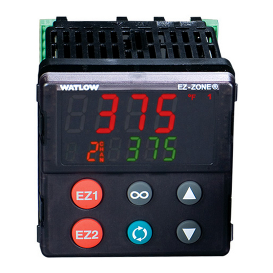
EZ-ZONE
User's Guide
L
I
M
I
T
RESET
Phone: +1 (507) 454-5300, Fax: +1 (507) 452-4507
http://www.watlow.com
PM
®
L
I
M
I
T
RESET
L
I
M
I
T
RESET
TOTAL
CUSTOMER
SATISFACTION
3 Y ear Warranty
ISO 9001
Registered Company
Winona, Minnesota USA
Made in the U.S.A.
Advertisement
Table of Contents

Related Manuals for Watlow EZ-ZONE PM


Summary of Contents for Watlow EZ-ZONE PM
- Page 1 Limit Controller Models TOTAL CUSTOMER SATISFACTION 3 Y ear Warranty ISO 9001 Registered Company Winona, Minnesota USA 1241 Bundy Boulevard., Winona, Minnesota USA 55987 Phone: +1 (507) 454-5300, Fax: +1 (507) 452-4507 http://www.watlow.com 0600-0057-0000 Rev. N Made in the U.S.A. August 2016...
- Page 2 Safety Information We use note, caution and warning symbols throughout this book to draw your attention to important operational and safety information. • A “NOTE” marks a short message to alert you to an important detail. • A “CAUTION” safety alert appears with information that is important for protecting your equipment and performance.
- Page 3 Warranty The EZ-ZONE PM is manufactured by ISO 9001-registered processes and is backed by a three- year warranty to the first purchaser for use, providing that the units have not been misap- plied. Since Watlow has no control over their use, and sometimes misuse, we cannot guar- antee against failure.
- Page 4 6. If the unit cannot be repaired, you will receive a letter of explanation and be given the option to have the unit returned to you at your expense or to have us scrap the unit. 7. Watlow reserves the right to charge for no trouble found (NTF) returns. This EZ-ZONE ®...
-
Page 5: Table Of Contents
Chapter 1: Overview . . . . . . . . . . . . . . . . . . . . . . . . . . . . . . . 4 Available EZ-ZONE PM Literature and Resources . . . . . . . . . . . . . . . . 4 Introduction . - Page 6 Table of Contents (cont .) Chapter 6: Setup Page . . . . . . . . . . . . . . . . . . . . . . . . . . . . . 54 Analog Input Menu .
- Page 7 Table of Contents (cont .) Modbus - Using Programmable Memory Blocks . . . . . . . . . . . . . . . 105 CIP - Communications Capabilities .
-
Page 8: Chapter 1: Overview
As an alternative to the DVD, all of the user documentation described above can also be found on the Watlow website. Click on the following link to find your document of choice: http://www.watlow.com/literature/index.cfm. Once there, simply type in the desired part number (or name) into the search box and download free copies. -
Page 9: Introduction
EZ-ZONE PM controllers offer options to reduce system complexity and the cost of control loop ownership. You can order the EZ-ZONE PM as a Limit, PID or an Integrated PID/Limit con- troller. You can also select from a number of industrial serial communications protocols as options to enable connectivity into a distributed control system or to simply help manage sys- tem performance over a network. -
Page 10: A Conceptual View Of The Pm
A Conceptual View of the PM The flexibility of the PM software and hardware allows for a large range of configurations. Ac- quiring a better understanding of the controller’s overall functionality and capabilities while at the same time planning out how the controller can be used will deliver maximum effective- ness in your application. -
Page 11: Outputs
Keep in mind that a function is a user-programmed internal process that does not execute any action outside of the controller. To have any effect outside of the controller, an output must be configured to respond to a function. Outputs Outputs can perform various functions or actions in response to information provided by a function such as, removal of the control voltage to a contactor;... - Page 12 EZ-ZONE ® PM Enhanced Limit PM4/6/8/9 Models - System Diagram (with communications options 2, 3, 5 or 6) EZ-ZONE PM Enhanced Limit Controller System Diagram with Communications Universal Sensor Input, Configuration Communications, Red/Green 7-Segment Display Input Output Functions Functions Output 1...
- Page 13 EZ-ZONE ® PM Enhanced Limit PM4/6/8/9 Models - Input/Output (no communications options 2, 3, 5 or 6) Universal Sensor Input, Configuration Communications, EZ-ZONE™ PM Enhanced Limit Controller Red/Green 7-Segment Display Output Input Functions Functions Output 1 Off, Limit, None, Switched dc/open collector, Limit Analog Input 1 Alarm...
- Page 14 EZ-ZONE ® PM Limit All Models System Diagram Universal Sensor Input, Configuration Communications, EZ-ZONE™ PM Limit Controller Red/Green 7-Segment Display Input Output Functions Functions Output 1 Off, Limit, None, Switched dc/open collector, Limit Alarm Analog Input 1 Form C mechanical (5 A) relay Controller Off, Thermocouple, RTD (100 , 1k ), Input Sensor...
-
Page 15: Chapter 2: Install And Wire
Chapter 2: Install and Wire Dimensions 1/32 DIN (PM3) 15.9 mm 0.63 in 53.3 mm 101.5 mm 2.10 in 4.00 in 31.2 mm 30.9 mm 1.23 in 1.22 in RESET Side Front 1/32 DIN (PM3) Recommended Panel Spacing 44.96 to 45.47 mm (1.77 to 1.79 inches) Recommended panel spacing 22.2 to 22.5 mm... -
Page 16: 1/16 Din (Pm6)
1/16 DIN (PM6) 15.8 mm (0.62 in) 101.6 mm 53.3 mm (4.00 in) (2.10 in) 53.3 mm (2.10 in) RESET Side Front 51.2 mm (2.02 in) 1/16 DIN (PM6) Recommended Panel Spacing 44.96 to 45.47 mm (1.77 to 1.79 inches) Recommended panel spacing 44.96 to 45.47 mm (1.77 to 1.79 inches) -
Page 17: 1/8 Din (Pm8) Vertical
1/8 DIN (PM8) Vertical 15.75 mm 53.34 mm (0.62 in) (2.10 in) 1.52 mm (0.06 in) 100.33 mm (3.95 in) 10.16 mm (0.40 in) 30.73 mm 54.8 mm (1.21 in) (2.16 in) 101.60 mm (4.00 in) 1/8 DIN (PM8) Vertical Recommended Panel Spacing 44.96 to 45.60 mm (1.77 to 1.79 inches) 92.00 to 92.80 mm... -
Page 18: 1/8 Din (Pm9) Horizontal
1/8 DIN (PM9) Horizontal 15.75 mm (0.62 in) 1.52 mm 100.33 mm (0.06 in) (3.95 in) 53.8 mm (2.16 in) 53.34 mm (2.10 in) 10.16 mm (0.40 in) 30.73 mm (1.21 in) 101.60 mm (4.00 in) 1/8 DIN (PM9) Horizontal Recommended Panel Spacing 92.00 to 92.80 mm (3.62 to 3.65 inches) 44.96 to 45.60 mm... -
Page 19: 1/4 Din (Pm4)
1/4 DIN (PM4) 15.75 mm (0.62 in) 1.52 mm 100.33 mm (0.06 in) (3.95 in) 100.33 mm (3.95 in) 12.70 mm (0.50 in) 30.73 mm (1.21 in) 100.84 mm (3.97 in) 1/4 DIN (PM4) Recommended Panel Spacing 92.0 to 93.0 mm (3.62 to 3.65 inches) 92.0 to 93.0 mm (3.62 to 3.65 inches) -
Page 20: Installation
Installation 1. Make the panel cutout using the mounting template dimensions in this chapter. Insert the case assembly into the panel cutout. 2. While pressing the case assembly firmly against the panel, slide the mounting collar over the back of the controller. - Page 21 Removing the Mounted Controller from Its Case 1. From the controller's face, pull out the tabs on each side until you hear it click. Pull out the tab on each side Grab the unit above and until you hear it click. below the face and pull for- ward.
-
Page 22: Wiring
Wiring Slot A Slot B Slot E Terminal Function Configuration Inputs Universal, RTD and Thermistor Inputs S2 (RTD) or current + Universal Sensor S3 (RTD), thermocouple -, current -, volts - Input 1: all configurations or potentiometer wiper, thermistor S1 (RTD), thermocouple + or volts +, therm- istor, potentiometer Outputs Switched dc/open collector... - Page 23 Wiring (cont .) Slot A Slot B Slot E Terminal Function Configuration EtherNet/IP™ and Modbus ® Communications (cont.) EtherNet/IP™ and Modbus TCP unused Slot B: EtherNet/IP™ and Modbus TCP unused PM6 _ _ _ _-[3] A A A AAA EtherNet/IP™ and Modbus TCP receive - Slot E: EtherNet/IP™...
- Page 24 Slot Orientation - Back View 1/8 DIN Vertical PM8 1/8 DIN Horizontal PM9 1/32 DIN Horizontal PM3 Power Dig I/O 5 & 6 485 Comms Output 1 Output 2 Input 1 1/16 DIN Vertical PM6 1/4 DIN Vertical PM4 Note: Slot B above can also be con- figured with a communications card.
-
Page 25: Pm Integrated Isolation Block
PM Integrated Isolation Block Digital Inputs & Outputs No Isolation Controller Power Supply 12 to 40VÎ (dc) Safety Isolation 20 to 28VÅ (ac) 100 to 240VÅ (ac) Switched DC, Open Collector, No Isolation Process outputs Controller Low Voltage Power Bus No Isolation Analog Input 1 Note:... - Page 26 Low Power ç PM_ _ [3,4] _ _ - _ A _ _ _ _ _ Warning: Use National Electric (NEC) or • Minimum/Maximum Ratings Slot C other country-specific standard power • 12 to 40VÎ (dc) wiring and safety practices when fuse power wiring and connecting this con-...
- Page 27 Input 1 Thermocouple ç PM_ [L] _ _ _ - _ A _ _ _ _ _ Warning: Use National Electric (NEC) or • 2kΩ maximum source resistance Slot A other country-specific standard • >20MΩ input impedance wiring and safety practices when wiring and connecting this con- •...
- Page 28 Input 1 Potentiometer ç PM_ [L] _ _ _ - _ A _ _ _ _ _ Warning: Use National Electric (NEC) or • Use a 1kΩ potentiometer. Slot A other country-specific standard wiring and safety practices when wiring and connecting this con- troller to a power source and to electrical sensors or peripheral devices.
- Page 29 Output 1, 3 Mechanical Relay, Form C ç Warning: Use National Electric (NEC) or • 5A at 240VÅ (ac) or other country-specific standard Slot A, B 30VÎ (dc) maximum re- normally open wiring and safety practices when wiring and connecting this con- sistive load common troller to a power source and to...
- Page 30 Output 2, 4 Mechanical Relay, Form A ç Warning: Use National Electric (NEC) or • 5A at 240VÅ (ac) or Slot B other country-specific standard 30VÎ (dc) maximum re- wiring and safety practices when wiring and connecting this con- sistive load troller to a power source and to •...
- Page 31 ç Warning: 1 Amp SSR Derating Curve Use National Electric (NEC) or other country-specific standard wiring and safety practices when wiring and connecting this con- troller to a power source and to electrical sensors or peripheral devices. Failure to do so may result in damage to equipment and property, and/or injury or loss of life.
- Page 32 Output 4 Switched DC ç Warning: Use National Electric (NEC) or • Maximum open cir- Slot B other country-specific standard common cuit voltage is 22 to wiring and safety practices when 25VÎ (dc) dc - wiring and connecting this con- troller to a power source and to •...
- Page 33 Output 1, 3 Switched DC/Open Collector ç Warning: Use National Electric (NEC) or Switched DC Switched DC Slot A, B common other country-specific standard • Maximum open circuit dc - (open collector) wiring and safety practices when common dc + voltage is 22 to 25VÎ...
- Page 34 T-/R- daisy-chain fashion when connecting multiple devices in a network. T+/R+ • Do not connect more than 16 EZ-ZONE PM controllers on a network. • Maximum network length: 1,200 meters (4,000 feet) • 1/8th unit load on EIA-485 bus PM [3,4,6,8,9] _ _ _ _ - [*] _ _ _ _ _ _...
- Page 35 • Two EIA-485 terminals of T/R are provided to assist in daisy-chain wiring. • Do not connect more than one EZ-ZONE PM controller on an EIA- 232 network. • Maximum number of EZ-ZONE controllers on a Modbus network is 247.
- Page 36 EtherNet/IP™, PCCC and Modbus TCP Communications ® Slot B, E RJ-45 pin T568B wire color Signal Slot B, E unused brown unused unused brown & white unused receive - green receive - unused white & blue unused unused blue unused receive + white &...
- Page 37 Network Status Indicator State Summary Requirement Not powered, If the device does not have an IP address (or is powered Steady Off no IP address off), the network status indicator shall be steady off. If the device has no established connections, but has ob- No connec- Flashing Green tained an IP address, the network status indicator shall...
- Page 38 Link Status Indicator State Summary Requirement Not powered, If the device cannot determine link speed or power is off, Steady Off unknown link the network status indicator shall be steady off. speed If cable is wired and connected correctly, the LED will be Green - - - - Green.
- Page 39 Ω resistor across pins VP and B, a 220 Ω resistor across pins B and A, and lastly, place a 390 Ω resistor across pins DG and A. • Do not connect more than 32 EZ-ZONE PM controllers on any given segment.
- Page 40 120 Ω resistor across T+/R+ and T-/R- of the last controller on a network. Only one protocol per port is available at a time: either Modbus RTU or Standard Bus. A Network Using Watlow's Standard Bus and an RUI/Gateway. 24V Power...
- Page 41 ST_ _ - (B or F) _ M _ -_ _ _ _ EZ-ZONE RM fuse power power common power power EZ-ZONE PM power power common common ® Wat lo w EZ-ZO N E P M L im i t Co n t r o ll er Chapter 2 Instal l and W i re •...
- Page 42 Connecting a Computer to PM Controls Using B&B 485 to USB Converter Address 2 Address 1 Port Data Format 38,400 baud 8 data bits PC Software Protocol - Standard Bus no parity EZ-ZONE Con gurator software 1 start bit 1 stop bit Use twisted pair wires such as Cat 5 cabling.
-
Page 43: Chapter 3: Keys And Displays
Chapter 3: Keys and Displays 1/32 DIN (PM3) Lower (Right, 32 DIN) Upper (Left, 32 DIN) Dis- Display: play: ® Indicates the limit is safE In the Home Page, displays the for an active mes- process value, otherwise dis- Attn sage. -
Page 44: Responding To A Displayed Message
Responding to a Displayed Message An active message will cause the display to toggle between the normal settings and the active message in the upper display and in the lower display. attn Your response will depend on the message and the controller settings. Some messages, such as Ramping and Tuning, indicate that a process is underway. -
Page 45: Chapter 4: Home Page
Chapter 4: Home Page Default Home Page Parameters Watlow's patented user-defined menu system improves operational efficiency. The user-de- fined Home Page provides you with a shortcut to monitor or change the parameter values that you use most often. The default Home Page is shown on the following page. When a pa- rameter normally located in the Setup Page or Operations Page is placed in the Home Page, it is accessible through both. - Page 46 Navigating the EZ-ZONE PM Limit Controller PM6 Shown, Applies to All Models ® ® [``Ai] [``70] [`Set] [``72] RESET RESET Home Page from anywhere: Press the Reset key for two seconds to return to the Home RESET Page. ® ®...
-
Page 47: Changing The Set Point
Changing the Set Point From the default Home Page the Limit Set Points, high and low, can be changed. If high and low limits have been configured push the Advance key one time and the Low Limit Set Point ‰ prompt will appear in the lower display while the current set point will be displayed LL. -
Page 48: Conventions Used In The Menu Pages
Point, ) will not appear unless the Limit Sides is set for low or both found on the Setup LL. S 1 page under the Limit Menu. Home Page Default Parameters Home Page Dis- Custom Menu Custom Menu Display play Parameter Name Number (defaults) -
Page 49: Display
62 (off) to register 368 and send that value to the control. Communication Protocols When using a communications protocol in conjunction with the EZ-ZONE PM there are two pos- sible ports (instances) used. Port 1 or instance 1 is always dedicated to Standard Bus commu- nications. -
Page 50: Modbus Introduction To The Modbus Protocol
360 (low order bytes) and 361 (high order bytes). The Modbus specification does not dictate which register should be high or low order there- fore, Watlow provides the user the ability to swap this order (Setup Page, Menu) from CoЛЏ... -
Page 51: Profibus Dp
Common Industrial Protocol (CIP) Introduction to CIP Both DeviceNet and EtherNet/IP use open object based programming tools and use the same addressing scheme. In the following menu pages notice the column header identified as CIP. There you will find the Class, Instance and Attribute in hexadecimal, (decimal in parenthesis) which makes up the addressing for both protocols. -
Page 52: Chapter 5: Operations Page
Chapter 5: Operations Page PM Operation Page Parameters To navigate to the Operations Page, follow the steps below: 1. From the Home Page, press both the Up ¿ and Down ¯ keys for three seconds. will ap- pear in the upper display and will appear in the lower display. -
Page 53: Analog Input Menu
Operations Page Data Type Modbus Class Pro- Parameter Name rame- Display Range Default Relative Ad- Instance fibus Description dress Attribute Index cess hex (dec) opEr Analog Input Menu Analog Input -1,999.000 to - - - - Instance 1 0x68 (104) 4001 float Analog Input Value... -
Page 54: Digital Input/Output Menu
Operations Page Data Type Modbus Class Pro- Parameter Name rame- Display Range Default Relative Ad- Instance fibus Description dress Attribute Index cess hex (dec) opEr Digital Input/Output Menu Digital Output (5 - - - - Instance 5 0x6A (106) 6007 uint do. -
Page 55: Alarm Menu
Operations Page Data Type Modbus Class Pro- Parameter Name rame- Display Range Default Relative Ad- Instance fibus Description dress Attribute Index cess hex (dec) Limit (1) Clear (0) - - - - Instance 1 0x70 (112) - - - - 12014 uint Clear Limit No Change (255) Map 1... - Page 56 Operations Page Data Type Modbus Class Pro- Parameter Name rame- Display Range Default Relative Ad- Instance fibus Description dress Attribute Index cess hex (dec) Alarm (1 to 4) - - - - Instance 1 0x6D - - - - 9026 uint A.
- Page 57 Operations Page Data Type Modbus Class Pro- Parameter Name rame- Display Range Default Relative Ad- Instance fibus Description dress Attribute Index cess hex (dec) No Dis- Alarm (1 to 4) No (59) - - - - Instance 1 0x6D - - - - 9010 uint Alarm Latched play...
-
Page 58: Chapter 6: Setup Page
Chapter 6: Setup Page Navigating the Setup Page To navigate to the Setup Page follow the steps below: 1. From the Home Page, press and hold both the Up ¿ and Down ¯ keys for six seconds. will appear in the upper display and will appear in the lower display. - Page 59 Output Function In- aLЛЏ COЛЏ stance Alarm Menu Communications Menu Active Level Action Function Alarm (1 to 4) Communications (1 aLЛЏ COЛЏ Function Instance to 2) Type a. t y Protocol LiЛЏ pCoL Alarm Source sr. a Standard Bus Ad- a.
- Page 60 IP Fixed Subnet ipg6 Part 6 Modbus TCP Enable ЛЏb. E EtherNet/IP Enable Eip. E CIP Implicit Assem- ao. n b bly Output Member Quantity CIP Implicit Assem- ai. n b bly Input Member Quantity DeviceNet™ Node Ad. d Address Baud Rate Device- BAUd Net™...
-
Page 61: Analog Input Menu
Setup Page CIP - Data Modbus Class Pro- Param- Type Parameter Name Display Range Default Relative Ad- Instance fibus eter Description dress Attribute Index Access hex (dec) Analog Input Menu Analog Input Thermo- Instance 1 0x68 4005 uint Off (62) Sensor Type couple or Map 1 Map 2... - Page 62 Setup Page CIP - Data Modbus Class Pro- Param- Type Parameter Name Display Range Default Relative Ad- Instance fibus eter Description dress Attribute Index Access hex (dec) Analog Input -100.00 to 1,000.00 Instance 1 0x68 4015 float s. L o Scale Low Map 1 Map 2 (104)
- Page 63 Setup Page CIP - Data Modbus Class Pro- Param- Type Parameter Name Display Range Default Relative Ad- Instance fibus eter Description dress Attribute Index Access hex (dec) Analog Input Curve A Instance 1 0x68 - - - - 4038 uint t.
-
Page 64: Digital Input/Output Menu
Setup Page CIP - Data Modbus Class Pro- Param- Type Parameter Name Display Range Default Relative Ad- Instance fibus eter Description dress Attribute Index Access hex (dec) Analog Input -1,999.000 to - - - - Instance 1 0x68 4001 float Analog Input Value 9,999.000°F or units Map 1 Map 2... - Page 65 Setup Page CIP - Data Modbus Class Pro- Param- Type Parameter Name Display Range Default Relative Ad- Instance fibus eter Description dress Attribute Index Access hex (dec) Digital Output (5 Instance 5 0x 6A 6005 uint Off (62) to 6) Map 1 Map 2 (106) RWES...
-
Page 66: Limit Menu
Setup Page CIP - Data Modbus Class Pro- Param- Type Parameter Name Display Range Default Relative Ad- Instance fibus eter Description dress Attribute Index Access hex (dec) Digital Input (5 to 6) 0 to 40 Instance 5 0x6E 10004 uint Function Instance Map 1 Map 2 (110) - Page 67 Setup Page CIP - Data Modbus Class Pro- Param- Type Parameter Name Display Range Default Relative Ad- Instance fibus eter Description dress Attribute Index Access hex (dec) Limit -1,999.000 to 0.0°F or Instance 1 0x70 12003 float LL. s Low Limit Set 9,999.000°F or units units Map 1 Map 2...
-
Page 68: Output Menu
Setup Page CIP - Data Modbus Class Pro- Param- Type Parameter Name Display Range Default Relative Ad- Instance fibus eter Description dress Attribute Index Access hex (dec) otpt Output Menu Output Digital (1 Output 1 Instance 1 0x6A 6005 uint Off (62) to 4) - Alarm... - Page 69 Setup Page CIP - Data Modbus Class Pro- Param- Type Parameter Name Display Range Default Relative Ad- Instance fibus eter Description dress Attribute Index Access hex (dec) Output Process (3) 1 to 4 Instance 3 0x76 18004 uint Function Instance Map 1 Map 2 (118) RWES...
-
Page 70: Alarm Menu
Setup Page CIP - Data Modbus Class Pro- Param- Type Parameter Name Display Range Default Relative Ad- Instance fibus eter Description dress Attribute Index Access hex (dec) Output Process (3) -1,999.000 to 100.0°F Instance 3 0x76 18012 float r. h i Range High 9,999.000°F or units or units... - Page 71 Setup Page CIP - Data Modbus Class Pro- Param- Type Parameter Name Display Range Default Relative Ad- Instance fibus eter Description dress Attribute Index Access hex (dec) Alarm (1 to 4) 0.001 to 9,999.000°F 1.0°F or Instance 1 0x6D 9003 float A.
- Page 72 Setup Page CIP - Data Modbus Class Pro- Param- Type Parameter Name Display Range Default Relative Ad- Instance fibus eter Description dress Attribute Index Access hex (dec) Alarm (1 to 4) Non- Instance 1 0x6D 9007 uint A. L A nLAt Non-Latching Latching...
- Page 73 Setup Page CIP - Data Modbus Class Pro- Param- Type Parameter Name Display Range Default Relative Ad- Instance fibus eter Description dress Attribute Index Access hex (dec) Alarm (1 to 4) 0 to 9,999 seconds Instance 1 0x6D 9021 uint A.
-
Page 74: Function Key
Setup Page CIP - Data Modbus Class Pro- Param- Type Parameter Name Display Range Default Relative Ad- Instance fibus eter Description dress Attribute Index Access hex (dec) Function Key Function Key (3 to High Instance 3 0x6E 10001 uint high High (37) Map 1 Map 2 (110) -
Page 75: Global Menu
Setup Page CIP - Data Modbus Class Pro- Param- Type Parameter Name Display Range Default Relative Ad- Instance fibus eter Description dress Attribute Index Access hex (dec) gLbL Global Menu 3005 uint Global °F Instance 1 0x67 °F (30) RWES Display Units Map 1 Map 2 (103) -
Page 76: Communications Menu
Setup Page CIP - Data Modbus Class Pro- Param- Type Parameter Name Display Range Default Relative Ad- Instance fibus eter Description dress Attribute Index Access hex (dec) Global None Instance 1 0x65 1013 uint USr. r FCty Factory (31) Restore Settings (101) Map 1 Map 2 nonE... - Page 77 Setup Page CIP - Data Modbus Class Pro- Param- Type Parameter Name Display Range Default Relative Ad- Instance fibus eter Description dress Attribute Index Access hex (dec) Communications (1 9,600 Instance 1 0x96 - - - - 17002 uint bAUd 9600 9,600 (188) or 2)
- Page 78 Setup Page CIP - Data Modbus Class Pro- Param- Type Parameter Name Display Range Default Relative Ad- Instance fibus eter Description dress Attribute Index Access hex (dec) Communications (1 Instance 1 0x96 17051 uint nU. S Yes (106) or 2) Map 1 Map 2 (150) No (59)
- Page 79 Setup Page CIP - Data Modbus Class Pro- Param- Type Parameter Name Display Range Default Relative Ad- Instance fibus eter Description dress Attribute Index Access hex (dec) Communications (2) °F Instance 2 0x96 17050 uint °F (30) Display Units Map 1 Map 2 (150) °C (15) Select which scale...
- Page 80 Setup Page CIP - Data Modbus Class Pro- Param- Type Parameter Name Display Range Default Relative Ad- Instance fibus eter Description dress Attribute Index Access hex (dec) Communications (2) Instance 2 96 (150) 17051 uint nU. S Yes (106) Non-volatile Save Map 1 Map 2 No (59) nU.S...
- Page 81 Setup Page CIP - Data Modbus Class Pro- Param- Type Parameter Name Display Range Default Relative Ad- Instance fibus eter Description dress Attribute Index Access hex (dec) Communications (2) 0 to 255 - - - - - - - - - - - - 17016 - - - - iP.
- Page 82 Setup Page CIP - Data Modbus Class Pro- Param- Type Parameter Name Display Range Default Relative Ad- Instance fibus eter Description dress Attribute Index Access hex (dec) Communications (2) 0 to 255 - - - - - - - - - - - - 17025 - - - - iP.
- Page 83 Setup Page CIP - Data Modbus Class Pro- Param- Type Parameter Name Display Range Default Relative Ad- Instance fibus eter Description dress Attribute Index Access hex (dec) Communications (2) 0 to 255 - - - - - - - - - - - - 17031 - - - - iP.
- Page 84 Setup Page CIP - Data Modbus Class Pro- Param- Type Parameter Name Display Range Default Relative Ad- Instance fibus eter Description dress Attribute Index Access hex (dec) Communications (2) Instance 2 96 (150) 17051 uint nU. S Yes (106) Non-volatile Save Map 1 Map 2 No (59) nV.S...
-
Page 85: Chapter 7: Factory Page
Chapter 7: Factory Page Navigating the Factory Page To navigate to the Factory Page follow the steps below: 1. From the Home Page, press and hold both the Advance and Infinity ˆ keys for six sec- ‰ onds. 2. Press the Up ¿ or Down ¯ key to view available menus. 3. - Page 86 IP Actual Address Part 5 ip. a 5 IP Actual Address Part 6 ip. a 6 FCty Calibration Menu Calibration (3) Electrical Measurement ЛЏu Electrical Input Offset ELi. o Electrical Input Slope ELi. S Electrical Output Offset ELo. o Electrical Output Slope ELo.
-
Page 87: Custom
Factory Page Class Data Modbus Instance Pro- Param- Type Parameter Name Display Range Default Relative Ad- Attri- fibus eter Description dress bute Index Access (dec) Cust fcty Custom Custom See: - - - - - - - - - - - - 14005 uint None nonE Low Limit Set Point... -
Page 88: Lock Menu
Factory Page Class Data Modbus Instance Pro- Param- Type Parameter Name Display Range Default Relative Ad- Attri- fibus eter Description dress bute Index Access (dec) Custom (1 to 20) 1 to 4 - - - - - - - - - - - - 14003 uint Instance ID RWES... - Page 89 Factory Page Class Data Modbus Instance Pro- Param- Type Parameter Name Display Range Default Relative Ad- Attri- fibus eter Description dress bute Index Access (dec) Security Setting 0 to 5 Instance 1 0x67 - - - - 3011 uint SLoC Write Security Map 1 Map 2...
-
Page 90: Unlock Menu
Factory Page Class Data Modbus Instance Pro- Param- Type Parameter Name Display Range Default Relative Ad- Attri- fibus eter Description dress bute Index Access (dec) Security Setting 10 to 999 - - - - - - - - - - - - 3018 uint pas. -
Page 91: Diagnostics Menu
Factory Page Class Data Modbus Instance Pro- Param- Type Parameter Name Display Range Default Relative Ad- Attri- fibus eter Description dress bute Index Access (dec) diag FCty Diagnostics Menu Diagnostics 15 characters - - - - - - - - 0x65 1009 string... - Page 92 Factory Page Class Data Modbus Instance Pro- Param- Type Parameter Name Display Range Default Relative Ad- Attri- fibus eter Description dress bute Index Access (dec) Diagnostics 0 to 255 - - - - - - - - - - - - - - - - 17014 iP.
-
Page 93: Calibration Menu
Factory Page Class Data Modbus Instance Pro- Param- Type Parameter Name Display Range Default Relative Ad- Attri- fibus eter Description dress bute Index Access (dec) Diagnostics 0 to 255 - - - - - - - - - - - - - - - - 17017 iP. - Page 94 Factory Page Class Data Modbus Instance Pro- Param- Type Parameter Name Display Range Default Relative Ad- Attri- fibus eter Description dress bute Index Access (dec) Calibration (3) -1,999.000 to 9,999.000 Instance 3 0x76 18005 float ELo. o Electrical Out- Map 1 Map 2 (118) RWES ELo.o...
-
Page 95: Chapter 8: Features
Chapter 8: Features Changing PM Integrated Model Number to PM Express . . . . . . . . . . . 92 Saving and Restoring Settings . . . . . . . . . . . . . . . . . . . . . . . . . . . . 94 Programming the Home Page . -
Page 96: Changing Pm Integrated Model Number To Pm Express
Changing PM Integrated Model Number to PM Express EZ-ZONE PM firmware revisions of 13 and above allow the user to switch between a PM Inte- grated control to a PM Express. Switching to a PM Express eliminates the complexity of the advanced PM Integrated control by allowing the user to operate with a simplified menu struc- ture. - Page 97 After switching the model number to a PM Express this document will no longer apply to the control. Click on the link that follows to acquire the latest version of the PM PID Express User’s Guide. http://www.watlow.com/en/Resources-And-Support/Technical-Li- brary/User-Manuals Once there, simply enter express in the “Keyword” field to find the appropriate docu- ment.
-
Page 98: Saving And Restoring Settings
Programming the Home Page Watlow’s patented user-defined menu system improves operational efficiency. The user-de- fined Home Page provides you with a shortcut to monitor or change the parameter values that you use most often. -
Page 99: Calibration
Calibration Before performing any calibration procedure, verify that the displayed readings are not within published specifications by inputting a known value from a precision source to the analog in- put. Next, subtract the dis- played value with the known value and compare this differ- ence to the published accuracy Negative Calibration Offset will compensate for the difference... - Page 100 Note: The user may only calibrate one sensor type. If the calibrator interferes with open ther- mocouple detection, set Sensor Type in Setup Page , Analog Input Menu millivolt instead of Thermocouple to avoid interference between the calibrator ЛЏ u and open thermocouple detect circuit for the duration of the calibration process.
-
Page 101: Filter Time Constant
Filter Time Constant Filtering smooths an input signal by applying a first-order filter time constant to the signal. Fil- tering the displayed value makes it easier to monitor. Filtering the signal may improve the performance of PID control in a noisy or very dynamic system. Unfiltered Input Signal Filtered Input Signal Time... -
Page 102: Range High And Range Low
Range High and Range Low With a process input, you must choose a value to represent the low and high ends of the current or voltage range. Choosing these values allows the controller’s display to be scaled into the actual working units of measurement. For example, the analog input from a humid- ity transmitter could represent 0 to 100 percent relative humidity as a process signal of 4 to 20mA. -
Page 103: Alarms
To check the firmware revision of your control do one of the following: 1. Cycle power to the control while observing the number in the top display (this momentary numerical display reflects the current installed firmware version). 2. Navigate to the Factory Page by simultaneously pushing and holding the Advance Key ‰... -
Page 104: Hysteresis
Hysteresis An alarm state is triggered when the process value reaches the high or low set point. Hystere- sis defines how far the process must return into the normal operating range before the alarm can be cleared. Hysteresis is a zone inside each alarm set point. This zone is defined by adding the hysteresis value to the low set point or subtracting the hysteresis value from the high set point. -
Page 105: Blocking
The process temperature has to enter the normal operating range beyond the hysteresis zone to activate the alarm function. If the EZ-ZONE PM has an output that is functioning as a deviation alarm, the alarm is blocked when the set point is changed, until the process value re-enters the normal operating range. - Page 106 Lockout Security sLoC rLoC Security Level Pages Home Page (cannot be changed) Operations Page Setup Page (cannot be changed) Factory Page Being able to change the page security level for the Operations and Profile pages allows a user to give access to the Profile Page while locking out the Operations Page. The following exam- ple shows how the Lockout feature may be used to accomplish this: Changing Security Levels: 1.
-
Page 107: Using Lockout Method 2 (Password Enable)
Although the Factory Page is always visible, some menus within it can be restricted. Lockout Security sLoC rLoC Factory Page Menus Security Level Menus Custom Menu Lockout Menu* Diagnostic Menu** Calibration Menu * Using lockout Method 1 with set to 0, all writable parameters within the control SLoC will be inhibited (not writable) with two exceptions, . - Page 108 2. Press the Up Key ¿ until appears in the upper display and will appear in the low- fCty er display. 3. Press the Advance Key until Password Enable appears in the bottom display and PAS. E ‰ change it to 4.
-
Page 109: Modbus - Using Programmable Memory Blocks
Passwords equal: 7. User a. If Rolling Password is Off, Password equals User Password roLL pass pas. u b. If Rolling Password is On, Password equals: ( x code) Mod 929 + 70 roLL pass pas . u 8. Administrator a. -
Page 110: Cip - Communications Capabilities
CIP. There you will find the Class, Instance and Attribute in hexadecimal, (decimal in parenthesis) which makes up the ad- dressing for both protocols. The Watlow implementation of CIP does not support connected explicit messages but fully supports unconnected explicit messaging. -
Page 111: Cip Implicit Assemblies
PM control. Watlow refers to these assemblies as the T to O (Target to Originator) and the O to T (Orig- inator to Target) assemblies where the Target is always the EZ-ZONE PM controller and the Originator is the PLC or master on the network. -
Page 112: Profibus Dp - (Decentralized Peripherals)
Software Configuration Using EZ-ZONE Configurator Software To enable a user to configure the PM control using a personal computer (PC), Watlow has pro- vided free software for your use. If you have not yet obtained a copy of this software insert the CD (Controller Support Tools) into your CD drive and install the software. - Page 113 3. Navigate to the “Watlow” folder and then the sub-folder “EZ-ZONE Configurator” 4. Click on EZ-ZONE Configurator to run. The first screen that will appear is shown below. If the PC is already physically connected to the EZ-ZONE PM control click the next button to go on-line. Note: When establishing communications from PC to the EZ-ZONE PM controller, an interface converter will be required.
- Page 114 After clicking on the “Next” button, the software will scan the network for the zone address- es specified while showing the progress made (as shown in the graphic below. When complete the software will display all of the available devices found on the network as shown below. Searching Network for Devices Available Network Devices Displayed The PM9L is shown highlighted above to bring greater clarity to the controller in focus.
- Page 115 When saving the configuration, note the location where the file will be placed (saved in) and enter the file name (File name) as well. The default path for saved files follows: Users\”Username”\My Documents\ Watlow\EZ-Zone Configurator\Saved Configu- rations The user can save the file to any folder of choice.
-
Page 116: Chapter 9: Appendix
Chapter 9: Appendix Troubleshooting Alarms, Errors and Control Issues Indication Description Possible Cause(s) Corrective Action Alarm won’t Alarm will not clear • Latching is active • Reset alarm when process clear or reset or reset with keypad is within range or disable or digital input latching •... - Page 117 Indication Description Possible Cause(s) Corrective Action Alarm Low Sensor input below • Temperature is less than • Check cause of under low alarm set point alarm set point temperature AL. L 1 AL. L 2 • Alarm is set to latching •...
- Page 118 Indication Description Possible Cause(s) Corrective Action Limit High Sensor input above • Temperature is greater • Check cause of over tem- high limit set point than limit set point perature Li. h 1 • Limit outputs latch and • Clear limit require reset •...
- Page 119 Indication Description Possible Cause(s) Corrective Action Temperature Process value con- • Controller output incor- • Verify output function is runway tinues to increase rectly programmed correct (heat or cool) or decrease past set • Thermocouple reverse • Correct sensor wiring point.
- Page 120 Detection of and Rules Around Abnormal Sensor Conditions Inputs Detection of Abnormal Conditions Thermocouple Shorted No direct detection, Open loop firmware detection. Open Yes, Parasitic pull-up Reversed Yes, firmware detection Current Source Shorted Range limiting only Open Range limiting only Reversed Range limiting only Voltage Source...
-
Page 121: Modbus - Programmable Memory Blocks
The screen shot above was taken from a program that can be found on the Watlow Support Tools DVD (shipped with the product) as well as on the Watlow website. On the DVD, it can be found under “Utility Tools” and is identified as “Modbus TCP Diagnostic Program for EZ-ZONE PM, RM and ST”. -
Page 122: Modbus - Programmable Memory Blocks
Modbus - Programmable Memory Blocks Assembly Definition Addresses and Assembly Working Addresses Assembly Definition Assembly Working Assembly Definition Assembly Working Addresses Addresses Addresses Addresses 40 & 41 200 & 201 80 & 81 240 & 241 42 & 43 202 & 203 82 &... - Page 123 Modbus Default Assembly Structure 80-119 Assembly Definition Assembly Definition Registers Assembly Working Addresses Assembly Working Default Pointers Registers Default Pointers Addresses Registers 100 & 101 Registers 260 & 261 Registers 80 & 81 Registers 240 & 241 Pointer 21 = 360 & 361 Pointer 31 = 1882 &...
-
Page 124: Cip Implicit Assembly Structures
CIP Implicit Assembly Structures CIP Implicit Assembly Originator (Master) to Target (PML) Assembly Parameter Assembly ST Data Class, Instance, Parameter Class, Instance, Members Type Data Type Attribute Attribute 0x77, 0x01, 0x01 DINT Control Loop 1, User Control Mode 0x97, 0x01, 0x01 DINT 0x77, 0x01, 0x02 DINT... - Page 125 CIP Implicit Assembly Target (PML) to Originator (Master) Assembly Parameter Assembly ST Data Class, Instance, Parameter Class, Instance, Members Type Data Type Attribute Attribute - - - - Cannot be changed Binary Device Status None 0x77, 0x02, 0x01 DINT Analog Input 1, Analog Input Value 0x68, 0x01, 0x01 REAL 0x77, 0x02, 0x02...
- Page 126 As can be seen on the previous page, the PML Implicit Assembly defaults (factory settings) to a populated assembly structure. If it is desired to modify any of the given assembly members there are many software tools available to do so. It is outside of the scope of this document to describe how to use those.
- Page 127 Compact Class 1 A through 7 A Instance i Class, Assembly Instance, Attribute C = 0x71 (113) Analog Input I = 1 to 4 Filtered Analog Input Value Read A = 1 Bits 16 to 31, Signed 16 bits with implied tenths precision (-32768.8 to 3276.7) Instance i Class, Assembly...
- Page 128 Compact Class 1 B through 7 B Instance i Assembly Input Loop Actual Tune Control Loop Output Power Error Error Control Status Status Status Mode Bits 0 to 10, Signed 10 bits with implied tenths precision (-100.0 to 100.0) Bit 11, Loop Tuning Status (0 = Off, 1 = Anything Else) Bits 12 and 13, Actual Control Mode (00 = Off, 01 = Manual, 10 = Auto) Bit 14, Loop Error Status (0 = None, 1 = Error) Bit 15, Analog Input Error (0 = None, 1 = Error)
- Page 129 Compact Class 8 A through 13 A Instance i + 8 Instance i + 15 Instance i + 14 Instance i + 13 Instance i + 12 Instance i + 11 Instance i + 10 Instance i + 9 Class, Assembly Instance, Attribute C = 0x71 (113)
- Page 130 Compact Class 8 B through 13 B Instance i + 7 Instance i + 6 Instance i + 5 Instance i + 4 Instance i + 3 Instance i + 1 Instance i Instance i + 2 Assembly Limit State Limit State Limit State Limit State...
- Page 131 Compact Class 14 A through 19 A Instance i Class, Assembly Instance, Attribute C = 0x71 (113) 14 A Alarm I = 1 to 4 Alarm Alarm Set Point High Clear A = 0x0E (14) Read/Write Bits 16 to 30, Signed 15 bits with implied tenths precision (-1638.4 to 1638.3) Bit 31, Alarm Clear (0 = Ignore, 1 = Clear) Instance i + 1 Class,...
- Page 132 Compact Class 14 B through 17 B Instance i Assembly Alarm 14 B Alarm Set Point Low Silence Bits 0 to 14, Signed 15 bits with implied tenths precision (-1638.4 to 1638.3) Bit 15, Alarm Silence (0 = Ignore, 1 = Silence) Instance i Assembly Input...
-
Page 133: Pm Specifications
PM Specifications LineVoltage/Power (Minimum/Maximum Ratings) • 85 to 264VÅ (ac), 47 to 63Hz • 20 to 28VÅ (ac), 47 to 63Hz • 12 to 40VÎ (dc) • 14VA maximum power consumption (PM4, 8 & 9) • 10VA maximum power consumption (PM6) •... - Page 134 Universal Input • Thermocouple, grounded or ungrounded sensors - >20MΩ input impedance • Max. 2kΩ source resistance • 3µA open sensor detection • RTD 2- or 3-wire, platinum, 100Ω and 1kΩ @ 0°C (32°F) calibration to DIN curve (0.00385 Ω/Ω/°C) •...
- Page 135 Operating Range Input Type Range Low Range High Units -210 1200 Deg C -270 1371 Deg C -270 Deg C -270 1300 Deg C -270 1000 Deg C 1767 Deg C 1767 Deg C 1816 Deg C 2315 Deg C 2315 Deg C F (PTII)
- Page 136 2 Digital Input/Output Option - 2 DIO • Digital input update rate 10Hz - DC voltage - Max. input 36V @ 3mA - Min. high state 3V at 0.25mA - Max. low state 2V - Dry contact - Min. open resistance 10kΩ - Max.
- Page 137 • Universal process/retransmit, Output range selectable: - 0 to 10VÎ (dc) into a min. 1kΩ load - 0 to 20mA into max. 800Ω load Resolution - dc ranges: 2.5mV nominal - mA ranges: 5µA nominal Calibration Accuracy - dc ranges: ±15mV - mA ranges: ±30µA Temperature Stability - 100 ppm/°C...
- Page 138 Modbus ® is a trademark of AEG Schneider Automation Inc. EtherNet/IP™ is a trademark of ControlNet International Ltd. used under license by Open DeviceNet Vendor Association, Inc. (ODVA). is a registered trademark of Underwriters Laboratories Inc. ® DeviceNet™ is a trademark of Open DeviceNet Vendors Association. Note: These specifications are subject to change without prior notice.
-
Page 139: Ordering Information For Enhanced Limit Controller Models
XX custom firmware, overlays, … Note: The model of controller that you have is one of many possible models in the EZ-ZONE PM family of controllers. To view the others, visit our website (http://www.watlow.com/en/ resources-and-support/Technical-Library/User-Manuals) and type EZ-ZONE into the Key- word field. - Page 140 Custom Options Standard EZ-ZONE face plate Note: The model of controller that you have is one of many possible models in the EZ-ZONE PM family of controllers. To view the others, visit our website (http://www.watlow.com/en/ resources-and-support/Technical-Library/User-Manuals) and type EZ-ZONE into the Key- word field.
-
Page 141: How To Reach Us
September 2014 Title of Authorized Representative Date of Issue Signature of Authorized Representative ® Wat lo w EZ-ZO N E P M L im i t Co n t r o ll er Appe ndix • • CE DOC EZ-ZONE PM-09-14... - Page 142 Tel: +60 3 8076 8745 Fax: +60 3 8076 7186 Website: www.watlow.com Email: vlee@watlow.com Website: www.watlow.com Watlow Electric Manufacturing Company (Shanghai) Co. Ltd. 瓦特龍電機股份有限公司 Room 501, Building 10, KIC Plaza 80143 高雄市前金區七賢二路189號 10樓之一 290 Songhu Road, Yangpu District Shanghai, China 200433 電話: 07-2885168 傳真: 07-2885568...
Need help?
Do you have a question about the EZ-ZONE PM and is the answer not in the manual?
Questions and answers