Table of Contents
Advertisement
Quick Links
0600-0061-0000 Rev. A
September 2008
EZ-ZONE
User's Manual
Rail Mount System
1241 Bundy Boulevard., Winona, Minnesota USA 55987
Phone: +1 (507) 454-5300, Fax: +1 (507) 452-4507 http://www.watlow.com
RM System
®
TOTAL
CUST T O O M M ER
CUS
ER
S S A A TISF
TISFA A CTI
CTIO O N N
3 Year Warranty
ISO 9001
ISO 9001
Registered Company
Winona, Minnesota USA
Made in the U.S.A.
$25.00
Advertisement
Chapters
Table of Contents

Related Manuals for Watlow EZ-ZONE RM


Summary of Contents for Watlow EZ-ZONE RM
- Page 1 CTIO O N N 3 Year Warranty ISO 9001 ISO 9001 Registered Company Winona, Minnesota USA 1241 Bundy Boulevard., Winona, Minnesota USA 55987 Phone: +1 (507) 454-5300, Fax: +1 (507) 452-4507 http://www.watlow.com 0600-0061-0000 Rev. A Made in the U.S.A. September 2008 $25.00...
- Page 2 This warranty does forced insulation for shock hazard not apply to damage resulting from transportation, alteration, mis- prevention. use or abuse. The purchaser must use Watlow parts to maintain all listed ratings. Do not throw in trash, use proper Technical Assistance recycling techniques or consult manufacturer for proper disposal.
- Page 3 7. Watlow reserves the right to charge for no trouble found (NTF) returns. The EZ-ZONE ® RM User’s Manual is copyrighted by Watlow Winona, Inc., ©...
-
Page 4: Table Of Contents
Table of Contents Chapter 1: Overview ........2 Chapter 2: Install and Wire . -
Page 5: Chapter 1: Overview
® ® Modbus RTU, EtherNet/IP™, Modbus TCP, De- the EZ-ZONE RM as a single or multi-loop PID con- viceNet™ troller or an over-under limit controller, or you can Additional control integration options combine both functions. The system allows for op- •... - Page 6 • Supports industry needs for process recording • Free standard bus communications port and free Three-Year Warranty PC software (EZ-ZONE Configurator) • Demonstrates Watlow’s reliability and product sup- Modules Allow for Greater Design Flexibility port • Allows PID loops to be added in increments of one.
- Page 7 A Conceptual View of the RM System • Real Time Clock • Data Logging The flexibility of the RM’s software and hardware al- • Auto-Configuration Backup lows a large range of configurations. Acquiring a bet- As can be seen above the RM system is fully scalable ter understanding of the controller’s overall function- with regards to power requirements, number of loops, ality and capabilities while at the same time plan-...
- Page 8 In this configuration the RUI and PC are con- the difference between an input tied to a real-world nected to the RM system via Watlow's Standard Bus device such as a thermocouple and one that is tied to where both will be able to talk directly to the RM an internal function.
- Page 9 In this configuration the HMI can be running any In this configuration the control module connected of a number of protocols communicating to the RM system through Watlow's RUI/Gateway. Available to the HMI is equipped with the Modbus RTU proto- col (RMCxxxxxxxxx1xx). It is important to note that...
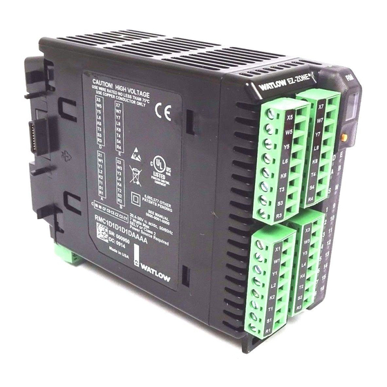
- Page 10 Module Orientation The picture below represents one of three possible RM modules. All three will have four slots on the face (slot A, B, D, and E) and one on the bottom (slot C) not shown. All of these slots are not always used on all modules.
- Page 11 EZ-ZONE RM-Control Module - Input/Output without 6-digital output card in slot E Digits 1, 2 & 3 = RMC Input Output Function Function Output 1 Current off, heat, cool, none, switched dc/open Transformer alarm, retransmit, collector, 5A mechanical Sense (CT),...
- Page 12 EZ-ZONE RM-Control Module - Input/Output with 6-digital output card in slot E Digits 1, 2 & 3 = RMC Output Input Function Function Output 1 Current off, heat, cool, none, switched dc/open Transformer alarm, retransmit, collector, 5A mechanical Sense (CT),...
- Page 13 EZ-ZONE RM-Expansion Module - Input/Output Digits 1, 2 & 3 = RME Input Connector Style Output Digit 4 = A, F, R, S Function Function None off, heat, cool, Digital Input (or Output) 1 Digital Output (or Input) 1 Reset limit...
- Page 14 EZ-ZONE RM-Access Module - Input/Output Digits 1, 2 & 3 = RMA Input Output Connector Style Function Function Digit 4 = A, F, R, S None, Modbus RTU 232/485, Modbus TCP & EtherNet/IP, Future Option or DeviceNet Digit 5 = A...
-
Page 15: Chapter 2: Install And Wire
Chapter 2: Install and Wire Dimensions As can be seen below the dimensions of the RM system will change slightly based on the type of connec- tor used. Module Removal Clearance Standard Connectors 147.07 mm ( 5.8 in ) 75.08 mm ( 3.0 in ) 44.45 mm ( 1.75 in ) - Page 16 Dimensions Module Removal Clearance *Ring Terminal Connectors 164.9 mm ( 6.5 in ) 80.54 mm ( 3.17 in ) 44.45 mm ( 1.75 in ) 101.60 mm 116.08 mm ( 4.00 in ) ( 4.57 in ) 15° 184.58 mm 51.56 mm ( 7.27 in ) ( 2.03 in )
- Page 17 Power Supplies DSP30 DSP60 71.00 mm 53.00 mm 2.795 in 2.087 in 1 2 3 4 1 2 3 4 + + - - vout ADJ. + + - - DC LO DC LO DC OK DC OK DSP60 DSP30 DSP100 89.9 mm 3.539 in...
- Page 18 RM Installation and Removal on a DIN Rail Modular Backplane Connector The picture on the right shows the Modular Back- plane Connector, both front and rear view. The rear view is bringing in to focus a metal clip. If the DIN rail is grounded the Modular Backplane Connector and the module connected to it will be also (recommended).
- Page 19 ç Warning: Module Removal Explosion hazard for hazardous lo- To remove a module from the cations. Do not disconnect while the Modular Backplane Connector circuit is live. find the red tab protruding from the bottom of the module and pull back on it as shown to the right.
- Page 20 Controller Module (RMCxxxxxxxxxxxx) Slot A Slot B Slot D Slot E Terminal Function Configuration Inputs Universal/Thermistor Input Part # Digits 4, 6, 8, 10 Input 1: RMC(1,2,3,4,5,6)xxxxxxxxxxx T_ (RTD) or current +, potentiometer wiper S_ (RTD), thermocouple -, current - or volts - Input 2: RMCxx(1,2,5,6)xxxxxxxxx R_ (RTD), thermocouple + or volts + Input 3: RMCxxxx(1,2,5,6)xxxxxxx...
- Page 21 Controller Module (RMCxxxxxxxxxxxx) Slot A Slot B Slot D Slot E Terminal Function Configuration Solid-State Relay 0.5 A, Form A Part # Digits 5, 7, 9, 11 Output 1: RMCx(G,M,S,T,Y,Z)xxxxxxxxxx Output 2: RMCx(G,M,S,T,Y,Z)xxxxxxxxxx normally open Output 3: RMCxxx(G,M,S,T,Y,Z)xxxxxxxx common Output 4: RMCxxx(G,M,S,T,Y,Z)xxxxxxxx Output 5: RMCxxxxx(G,M,S,T,Y,Z)xxxxxx Output 6: RMCxxxxx(G,M,S,T,Y,Z)xxxxxx Output 7: RMCxxxxxxx(G,M,S,T,Y,Z)xxxx...
- Page 22 Expansion Module (RMEx-xxxx-xxx) Slot A Slot B Slot D Slot E Terminal Function Configuration Inputs/Outputs - - - - - - Normally open Solid-State Relay (SSR) - - - - - - Normally open Part # Digits 5, 7 - - - - - - Common Slot A: RMEx-(K)xxx-xxx...
- Page 23 Slot C Terminal Function Configuration Power input: ac or dc+ Power input: ac or dc- Standard Bus EIA-485 common Standard Bus Standard Bus EIA-485 T-/R- Standard Bus EIA-485 T+/R+ Inter-module Bus Inter-module Bus Inter-module Bus Inter-module Bus All Modules - Front View - Standard Connector Slot E Slot D...
- Page 24 RM System Isolation Blocks Digital Inputs and No Isolation Outputs Switched DC, Open No Isolation Collector, Process Outputs Low-voltage Analog Input 1 Isolation Low-voltage Analog Input 2 Isolation Controller Low voltage power bus Low Voltage Power Supply Isolation 20.4 to 30.8VÎ (dc) Low-voltage internal bus Analog Input 3...
- Page 25 Controller Module Wiring (RMCxxxxxxxxxxxx) ç Warning: Use National Electric (NEC) or other Low Power country-specific standard wiring and safety practices when wiring and RMC- ALL Model Numbers connecting this controller to a power source and to electrical sensors or pe- ripheral devices.
- Page 26 Input 1, 2, 3, 4 Thermistor ç Warning: RMC Part # Digits 4, 6, 8, 10 Use National Electric (NEC) or other Slot A, B, D, E country-specific standard wiring and safety practices when wiring and connecting this controller to a power source and to electrical sensors or pe- •...
- Page 27 Input 1, 2, 3, 4 Potentiometer ç RMC Part # Digits 4, 6, 8, 10 Warning: Use National Electric (NEC) or other Slot A, B, D, E country-specific standard wiring and safety practices when wiring and connecting this controller to a power source and to electrical sensors or pe- •...
- Page 28 Output 1, 3, 5, 7 Switched DC/Open Collector ç Warning: RMC Part # Digit 5, 7, 9, 11 is U, D, E, F or G Use National Electric (NEC) or other Switched DC country-specific standard wiring and Switched DC safety practices when wiring and •...
- Page 29 ç Output 2, 4, 6, 8 Mechanical Relay, Form A Warning: Use National Electric (NEC) or other RMC Part # Digit 5, 7, 9, 11 is B or F country-specific standard wiring and Slot A, B, D, E safety practices when wiring and connecting this controller to a power •...
- Page 30 Outputs 1, 3, 5, 7 Solid-State Relay, Form A ç Warning: RMC Part # Digit 5, 7, 9, 11 is G, M, S, T, Y or Z Use National Electric (NEC) or other country-specific standard wiring and • 1 A at 20 to 264VÅ (ac) Slot A, B, D, E safety practices when wiring and normally open...
- Page 31 Expansion Module Wiring (RMEx-xxxx-xxxx) ç Warning: Low Power • 20.4 to 30.8 V Å (ac) / Î (dc) Use National Electric (NEC) or other country-specific standard wiring and • 47 to 63 Hz safety practices when wiring and • Expansion module power consumption, 7 Watts maximum connecting this controller to a power •...
- Page 32 ç Outputs 1-4, 7-10, 13-16 QUAD Mechanical Relays, Form A Warning: Use National Electric (NEC) or other RME Part # Digit 5, 6, or 7 is J country-specific standard wiring and safety practices when wiring and Slot A, B, D, E Mechanical Relay connecting this controller to a power normally open...
- Page 33 T+/R+ CLASS I, DIVISION 2. terminal of the EIA-485 port. • Do not connect more than one T-/R- • Do not route network wires EZ-ZONE RM controller on an ç 232 common with power wires. Connect net- EIA-232 network. Warning:...
- Page 34 EtherNet/IP™ and Modbus TCP Communications RMA Part # Digit 5 and 6 is A3 Slot E • Do not route net- RJ-45 T568B wire Signal Slot unused work wires with color power wires. unused brown unused • Connect one Ether- net cable per control- receive - brown &...
- Page 35 Split Rail Configuration able power supplied and the loading affect of all RM Expansion RM Controller Module Module of the modules used. Watlow provides three op- RMCxxxxxxxxxAxx RMExxxxxxxxxxxx Slot E Slot D Slot E Slot D...
- Page 36 EZ-ZONE common RUI/Gateway EZKB-_A_ _-_ _ _ _ common common A network using Watlow's Standard A network using Modbus RTU. Bus and an RUI/Gateway. Note: Avoid continuous writes within loops. Excessive writes to EEPROM will cause premature EEPROM failure. The EEPROM is rated for 1,000,000 writes ®...
-
Page 37: Chapter 3: Using A Remote User Interface (Rui) With Rm System
Indicates whether the temper- process value, otherwise dis- ature is displayed in Fahren- plays the value of the param- heit or Celsius. eter in the lower display. WATLOW EZ-ZONE ® Output Activity: Zone Display: Number lights indicate activ- Indicates the controller zone ity of outputs 1 through 5. - Page 38 Navigating the EZ-ZONE RM Controller EZ-ZONE WATLOW ® EZ-ZONE ® WATLOW [``Ai] [``70] [`Set] [``72] ˆ Home Page from anywhere: Press the Infinity Key for two seconds to return to the Home Page. EZ-ZONE ® EZ-ZONE ® WATLOW WATLOW [``70]...
-
Page 39: Chapter 4: Home Pages
Chapter 4: Home Pages Default Control Module Home Page Pa- rameters The Home Page is a customized list of as many as is in the upper display and the Closed Loop Set Point 20 parameters that can be configured and changed (read-write) is in the lower display. - Page 40 Default Control Module Home Page Display Parameter Name Setting Range Default Appears If Description [Attn] Attention [AL; L 1] to [AL; L 8] Alarm Low 1 to 8 an alarm or error message is ac- An active message will cause the [AL;...
- Page 41 Default Expansion Module Home Page Pa- rameters The Home Page is a customized list of as many as 20 parameters that can be configured and changed in the Custom Menu [ CUSt] (Factory Page). The At- tention [Attn] parameter appears only if there is an active message.
-
Page 42: Chapter 5: Operations Pages
Chapter 5: Operations Pages Control Module Operation Page Parameters Calculating the Modbus Register To go to the Operations Page from the Home Page, press both the Up ¿ and Down ¯ keys for three sec- The tables below list only the register of the first in- onds. - Page 43 [`Ctr] [MAt] [P; S tA] [oPEr] Counter Menu [oPEr] Math Menu [oPEr] Profile Status Menu [```1] [```1] [```1] [`Ctr] Counter 1 [MAt] Math 1 [P; S tA] Profile Status 1 [`Cnt] Count [`Su; A ] Source Value A [P; S tr] Profile Start [`Su;...
- Page 44 Control Module • Operations Page Display Parameter name Range Default Appears If Modbus Data Description Type Class instance 1 & Read/ Instance [offset] Write Attribute see below hex (dec) [``Pu] [```1] [```2] [```3] [```4] [oPEr] [``Pu] [``Pu] [``Pu] [``Pu] Process Value Menu Process Value 1 Process Value 2 Process Value 3 Process Value 4...
- Page 45 Control Module • Operations Page Display Parameter name Range Default Appears If Modbus Data Description Type Class instance 1 & Read/ Instance [offset] Write Attribute see below hex (dec) [`ACt] [```1] [```8] [oPEr] [`ACt] [`ACt] Action Menu Action 1 to Action 8 [`Ei;...
- Page 46 Control Module • Operations Page Display Parameter name Range Default Appears If Modbus Data Description Type Class instance 1 & Read/ Instance [offset] Write Attribute see below hex (dec) [A; t SP] Loop (1 to 4) 50.0 to 200.0% 90.0 Heat Algo- 2258 97 (151)
- Page 47 Control Module • Operations Page Display Parameter name Range Default Appears If Modbus Data Description Type Class instance 1 & Read/ Instance [offset] Write Attribute see below hex (dec) [``dB] Loop (1 to 4) -1,000.0 to 1,000.0°F or always 2238 97 (151) float [ db]...
- Page 48 Control Module • Operations Page Display Parameter name Range Default Appears If Modbus Data Description Type Class instance 1 & Read/ Instance [offset] Write Attribute see below hex (dec) [`CU; r ] Current (1 to 4) -1,999.000 to 9,999.000 always 1380 73 (115) float...
- Page 49 Control Module • Operations Page Display Parameter name Range Default Appears If Modbus Data Description Type Class instance 1 & Read/ Instance [offset] Write Attribute see below hex (dec) [``o; u ] Timer (1 to 4) [`off] Off (62) always 4338 83 (131) [ o.v]...
- Page 50 Control Module • Operations Page Display Parameter name Range Default Appears If Modbus Data Description Type Class instance 1 & Read/ Instance [offset] Write Attribute see below hex (dec) [``o; u ] Logic (1 to 4) [`off] Off (62) always 3746 7F (127) [ o.v]...
- Page 51 Control Module • Operations Page Display Parameter name Range Default Appears If Modbus Data Description Type Class instance 1 & Read/ Instance [offset] Write Attribute see below hex (dec) [`o; u 1] Special Output Function (1 -1,999.000 to 9,999.000°F or always 4978 87 (135)
- Page 52 Control Module • Operations Page Display Parameter name Range Default Appears If Modbus Data Description Type Class instance 1 & Read/ Instance [offset] Write Attribute see below hex (dec) [S; t yp] Profile Status [UStP] Unused Step (50) a profile is 5304 7A (122) [S.typ]...
- Page 53 Control Module • Operations Page Display Parameter name Range Default Appears If Modbus Data Description Type Class instance 1 & Read/ Instance [offset] Write Attribute see below hex (dec) [`S; t i] Profile Status 0 to 9,999.000 seconds always 5296 7A (122) float [ S.ti]...
- Page 54 Control Module • Operations Page Display Parameter name Range Default Appears If Modbus Data Description Type Class instance 1 & Read/ Instance [offset] Write Attribute see below hex (dec) [``JC] Profile Status 0 to 9,999 always 5298 7A (122) Jump Count Remaining [ JC] View the jump counts re- A (10)
-
Page 55: Expansion Module Operation Page Parameters
Expansion Module Expansion Module Operation Page Parameters Calculating the Modbus Register To go to the Operations Page from the Home Page, press both the Up ¿ and Down ¯ keys for three sec- The tables below list only the register of the first in- onds. - Page 56 Expansion Module • Operations Page Display Parameter name Range Default Appears If Modbus Data Description Type Class instance & Read/ Instance 1 [offset] Write Attribute see below hex (dec) [`dio] [```1] [``24] [oPEr] [`dio] [`dio] Digital Input/ Digital Input Digital Input Output Menu Output 1 Output 24...
- Page 57 Expansion Module • Operations Page Display Parameter name Range Default Appears If Modbus Data Description Type Class instance & Read/ Instance 1 [offset] Write Attribute see below hex (dec) [`C; E r] Current (1 to 4) [open] Open (65) None always 1082 73 (115)
- Page 58 Expansion Module • Operations Page Display Parameter name Range Default Appears If Modbus Data Description Type Class instance & Read/ Instance 1 [offset] Write Attribute see below hex (dec) [`Ctr] [```1] [```8] [oPEr] [`Ctr] [`Ctr] Counter Menu Counter 1 Counter 8 [`Cnt] Counter (1 to 8) 0 to 9,999...
- Page 59 Expansion Module • Operations Page Display Parameter name Range Default Appears If Modbus Data Description Type Class instance & Read/ Instance 1 [offset] Write Attribute see below hex (dec) [MAt] [```1] [```8] [oPEr] [MAt] [MAt] Math Menu Math 1 to Math 8 [`Su;...
- Page 60 Expansion Module • Operations Page Display Parameter name Range Default Appears If Modbus Data Description Type Class instance & Read/ Instance 1 [offset] Write Attribute see below hex (dec) [`o; u 1] Special Output Function (1 to 4) -1,999.000 to 9,999.000°F always 6638 87 (135)
-
Page 61: Access Module Operation Page Parameters
Access Module Access Module Operation Page Parameters [dLog] To go to the Operations Page from the Home Page, [oPEr] Data Logging Menu press both the Up ¿ and Down ¯ keys for three sec- [```1] [dLog] Data Logging 1 (to 3) onds. - Page 62 Access Module • Operations Page Display Parameter name Range Default Appears If Modbus Data Description Type Class instance 1 & Read/ Instance [offset] Write Attribute see below hex (dec) [dLog] [```1] [```2] [```3] [oPEr] [dLog] [dLog] [dLog] Data Logging Menu Data Logging 1 Data Logging 2 Data Logging 3...
-
Page 63: Chapter 6: Setup Pages
Chapter 6: Setup Pages Control Module Setup Page Parameters To go to the Setup Page from the Home Page, press the submenus. both the Up ¿ and Down ¯ keys for six seconds. • Press the Advance Key ‰ to move through the pa- [``Ai] will appear in the upper display and [`Set] rameters of the menu or submenu. - Page 64 [``t; t ] Valve Travel Time [`Lnr] [`LgC] [``db] Dead Band [`Set] Linearization Menu [`Set] Logic Menu [`os; 1 ] Output Size 1 [```1] [```1] [`os; 2 ] Output Size 2 [`Lnr] Linearization 1 (to 4) [`LgC] Logic 1 (to 4 [`os;...
- Page 65 Calculating the Modbus Register To go to the Setup Page from the Home Page, press both the Up ¿ and Down ¯ keys for six seconds. The tables below list only the register of the first in- [``Ai] will appear in the upper display and [`Set] stance of each parameter.
- Page 66 Control Module • Setup Page Dis- Parameter name Range Default Appears If Modbus Data play Description Type Class instance 1 & Instance [offset] Read/ Attribute see below Write hex (dec) [`S; L o] Input (1 to 4) -100.0 to 1,000.0 Sensor Type 68 (104) float...
- Page 67 Control Module • Setup Page Dis- Parameter name Range Default Appears If Modbus Data play Description Type Class instance 1 & Instance [offset] Read/ Attribute see below Write hex (dec) [`FiL] Input (1 to 4) 0.0 to 60.0 seconds always 68 (104) float Filter...
- Page 68 Control Module • Setup Page Dis- Parameter name Range Default Appears If Modbus Data play Description Type Class instance 1 & Instance [offset] Read/ Attribute see below Write hex (dec) [SFn; C ] Process Value (1 to 4) [nonE] None (61) None Function is 3404...
- Page 69 Control Module • Setup Page Dis- Parameter name Range Default Appears If Modbus Data play Description Type Class instance 1 & Instance [offset] Read/ Attribute see below Write hex (dec) [``C; P ] Process Value (1 to 4) -1999.000 to 9999.000 100.0 Function is set 3446...
- Page 70 Control Module • Setup Page Dis- Parameter name Range Default Appears If Modbus Data play Description Type Class instance 1 & Instance [offset] Read/ Attribute see below Write hex (dec) [``Fn] [SoF; 1 ] Special Function Output Digital Output (1 to 12) Direction is set 1028 6A (106)
- Page 71 Control Module • Setup Page Dis- Parameter name Range Default Appears If Modbus Data play Description Type Class instance 1 & Instance [offset] Read/ Attribute see below Write hex (dec) [`o; h i] Digital Output (1 to 12) 0.0 to 100.0 100.0 Direction is 1038...
- Page 72 Control Module • Setup Page Dis- Parameter name Range Default Appears If Modbus Data play Description Type Class instance 1 & Instance [offset] Read/ Attribute see below Write hex (dec) [SFn; A ] Action (1 to 8) [Ent; A ] Profile Event Out A (233) None always 1590...
- Page 73 Control Module • Setup Page Dis- Parameter name Range Default Appears If Modbus Data play Description Type Class instance 1 & Instance [offset] Read/ Attribute see below Write hex (dec) [SP; L l] Limit (1 to 4) -1,999.000 to 9,999.000 -1,999.000 always 70 (112) float...
- Page 74 Control Module • Setup Page Dis- Parameter name Range Default Appears If Modbus Data play Description Type Class instance 1 & Instance [offset] Read/ Attribute see below Write hex (dec) [`r; E n] Control Loop (1 to 4) [``no] No (59) always 2540 6B (107)
- Page 75 Control Module • Setup Page Dis- Parameter name Range Default Appears If Modbus Data play Description Type Class instance 1 & Instance [offset] Read/ Attribute see below Write hex (dec) [FAiL] Control Loop (1 to 4) [`oFF] Off, sets output power to User always 2524...
- Page 76 Control Module • Setup Page Dis- Parameter name Range Default Appears If Modbus Data play Description Type Class instance 1 & Instance [offset] Read/ Attribute see below Write hex (dec) [`L; S P] Control Loop (1 to 4) -1,999.000 to 9,999.000°F or units -1,999°F always 2504...
- Page 77 Control Module • Setup Page Dis- Parameter name Range Default Appears If Modbus Data play Description Type Class instance 1 & Instance [offset] Read/ Attribute see below Write hex (dec) [`S2; A ] Output (1 to 12) 1 to 16 1042 6A (106) Source Zone A...
- Page 78 Control Module • Setup Page Dis- Parameter name Range Default Appears If Modbus Data play Description Type Class instance 1 & Instance [offset] Read/ Attribute see below Write hex (dec) [``Fn] Output (1, 3, 5 or 7 process) [`oFF] Off (62) always 842 (1) 76 (118)
- Page 79 Control Module • Setup Page Dis- Parameter name Range Default Appears If Modbus Data play Description Type Class instance 1 & Instance [offset] Read/ Attribute see below Write hex (dec) [`r; h i] Output (1, 3, 5 or 7 process) -1,999.000 to 9,999.000°F or units 9,999.0°F always...
- Page 80 Control Module • Setup Page Dis- Parameter name Range Default Appears If Modbus Data play Description Type Class instance 1 & Instance [offset] Read/ Attribute see below Write hex (dec) [`A; h y] Alarm (1 to 8) 0.001 to 9,999.000°F or units 1.0°F or Type is not set 1744...
- Page 81 Control Module • Setup Page Dis- Parameter name Range Default Appears If Modbus Data play Description Type Class instance 1 & Instance [offset] Read/ Attribute see below Write hex (dec) [`C; d t] Current (1 to 4) 3 to 59 always 1402 73 (115)
- Page 82 Control Module • Setup Page Dis- Parameter name Range Default Appears If Modbus Data play Description Type Class instance 1 & Instance [offset] Read/ Attribute see below Write hex (dec) [`iP; 1 ] Linearization (1 to 4) -1,999.000 to 9,999.000 always 4534 86 (134)
- Page 83 Control Module • Setup Page Dis- Parameter name Range Default Appears If Modbus Data play Description Type Class instance 1 & Instance [offset] Read/ Attribute see below Write hex (dec) [`oP; 7 ] Linearization (1 to 4) -1,999.000 to 9,999.000 always 4566 86 (134)
- Page 84 Control Module • Setup Page Dis- Parameter name Range Default Appears If Modbus Data play Description Type Class instance 1 & Instance [offset] Read/ Attribute see below Write hex (dec) [SFn; A ] Compare (1 to 4) [nonE] None (61) None 4000 80 (128)
- Page 85 Control Module • Setup Page Dis- Parameter name Range Default Appears If Modbus Data play Description Type Class instance 1 & Instance [offset] Read/ Attribute see below Write hex (dec) [tMr] [```1] [```2] [```3] [```4] [`Set] [tMr] [tMr] [tMr] [tMr] Timer Menu Timer 1 Timer 2...
- Page 86 Control Module • Setup Page Dis- Parameter name Range Default Appears If Modbus Data play Description Type Class instance 1 & Instance [offset] Read/ Attribute see below Write hex (dec) [SFn; B ] Timer (1 to 4) [Ent; A ] Profile Event Out A (233) None Retentive 4322...
- Page 87 Control Module • Setup Page Dis- Parameter name Range Default Appears If Modbus Data play Description Type Class instance 1 & Instance [offset] Read/ Attribute see below Write hex (dec) [`Ctr] [```1] [```2] [```3] [```4] [`Set] [`Ctr] [`Ctr] [`Ctr] [`Ctr] Counter Menu Counter 1 Counter 2...
- Page 88 Control Module • Setup Page Dis- Parameter name Range Default Appears If Modbus Data play Description Type Class instance 1 & Instance [offset] Read/ Attribute see below Write hex (dec) [SFn; B ] Counter (1 to 4) [Ent; A ] Profile Event Out A (233) None 4162 82 (130)
- Page 89 Control Module • Setup Page Dis- Parameter name Range Default Appears If Modbus Data play Description Type Class instance 1 & Instance [offset] Read/ Attribute see below Write hex (dec) [SFn; A ] Logic (1 to 4) [Ent; A ] Profile Event Out A (233) None 3680 7F (127)
- Page 90 Control Module • Setup Page Dis- Parameter name Range Default Appears If Modbus Data play Description Type Class instance 1 & Instance [offset] Read/ Attribute see below Write hex (dec) [SFn; b ] Logic (1 to 4) [Ent; A ] Profile Event Out A (233) None 3682 7F (127)
- Page 91 Control Module • Setup Page Dis- Parameter name Range Default Appears If Modbus Data play Description Type Class instance 1 & Instance [offset] Read/ Attribute see below Write hex (dec) [SFn; C ] Logic (1 to 4) [Ent; A ] Profile Event Out A (233) None 3684 7F (127)
- Page 92 Control Module • Setup Page Dis- Parameter name Range Default Appears If Modbus Data play Description Type Class instance 1 & Instance [offset] Read/ Attribute see below Write hex (dec) [SFn; D ] [Ent; A ] Profile Event Out A (233) Logic (1 to 4) None 3686...
- Page 93 Control Module • Setup Page Dis- Parameter name Range Default Appears If Modbus Data play Description Type Class instance 1 & Instance [offset] Read/ Attribute see below Write hex (dec) [SFn; E ] [Ent; A ] Profile Event Out A (233) Logic (1 to 4) None 3688...
- Page 94 Control Module • Setup Page Dis- Parameter name Range Default Appears If Modbus Data play Description Type Class instance 1 & Instance [offset] Read/ Attribute see below Write hex (dec) [SFn; F ] Logic (1 to 4) [Ent; A ] Profile Event Out A (233) None 3690 7F (127)
- Page 95 Control Module • Setup Page Dis- Parameter name Range Default Appears If Modbus Data play Description Type Class instance 1 & Instance [offset] Read/ Attribute see below Write hex (dec) [SFn; g ] Logic (1 to 4) [Ent; A ] Profile Event Out A (233) None 3692 7F (127)
- Page 96 Control Module • Setup Page Dis- Parameter name Range Default Appears If Modbus Data play Description Type Class instance 1 & Instance [offset] Read/ Attribute see below Write hex (dec) [SFn; h ] Logic (1 to 4) [Ent; A ] Profile Event Out A (233) None 3694 7F (127)
- Page 97 Control Module • Setup Page Dis- Parameter name Range Default Appears If Modbus Data play Description Type Class instance 1 & Instance [offset] Read/ Attribute see below Write hex (dec) [MAt] [```1] [```8] [`Set] [MAt] [MAt] Math Menu Math 1 Math 8 [``Fn] Math (1 to 8)
- Page 98 Control Module • Setup Page Dis- Parameter name Range Default Appears If Modbus Data play Description Type Class instance 1 & Instance [offset] Read/ Attribute see below Write hex (dec) [SFn; b ; ] Math (1 to 8) [nonE] None (61) None Function is 2842...
- Page 99 Control Module • Setup Page Dis- Parameter name Range Default Appears If Modbus Data play Description Type Class instance 1 & Instance [offset] Read/ Attribute see below Write hex (dec) [SFn; D ] Math (1 to 8) [nonE] None (61) None Function is 2846...
- Page 100 Control Module • Setup Page Dis- Parameter name Range Default Appears If Modbus Data play Description Type Class instance 1 & Instance [offset] Read/ Attribute see below Write hex (dec) [`S; L o] Math (1 to 8) -1,999.000 to 9,999.000 always 2886 7D (125)
- Page 101 Control Module • Setup Page Dis- Parameter name Range Default Appears If Modbus Data play Description Type Class instance 1 & Instance [offset] Read/ Attribute see below Write hex (dec) [SFn; b ] Special Output (1 to 4) [nonE] None (61) None Function is set 4962...
- Page 102 Control Module • Setup Page Dis- Parameter name Range Default Appears If Modbus Data play Description Type Class instance 1 & Instance [offset] Read/ Attribute see below Write hex (dec) [`o; S 4] Special Output (1 to 4) 0 to 9,999 Function is set 5020 87 (135)
- Page 103 Control Module • Setup Page Dis- Parameter name Range Default Appears If Modbus Data play Description Type Class instance 1 & Instance [offset] Read/ Attribute see below Write hex (dec) [`GSE] Profile [`oFF] Off (62) always 5290 7A (122) Guaranteed Soak Enable [ gSE] [``on] On (63) Enables the guaranteed soak...
- Page 104 Control Module • Setup Page Dis- Parameter name Range Default Appears If Modbus Data play Description Type Class instance 1 & Instance [offset] Read/ Attribute see below Write hex (dec) [SFn; A ] Profile [Ent; A ] Profile Event Out A (233) None 5320 7A (122)
- Page 105 Control Module • Setup Page Dis- Parameter name Range Default Appears If Modbus Data play Description Type Class instance 1 & Instance [offset] Read/ Attribute see below Write hex (dec) [SFn; ] ; C ] Profile [Ent; A ] Profile Event Out A (233) None 5326 7A (122)
- Page 106 Control Module • Setup Page Dis- Parameter name Range Default Appears If Modbus Data play Description Type Class instance 1 & Instance [offset] Read/ Attribute see below Write hex (dec) [SFn; E ] Profile [nonE] None (61) None 5390 7A (122) Source Function E [SFn.E] [MAt] Math (240)
- Page 107 Control Module • Setup Page Dis- Parameter name Range Default Appears If Modbus Data play Description Type Class instance 1 & Instance [offset] Read/ Attribute see below Write hex (dec) [SFn; G ] Profile [nonE] None (61) None 5394 7A (122) Source Function G [SFn.g] [MAt] Math (240)
- Page 108 Control Module • Setup Page Dis- Parameter name Range Default Appears If Modbus Data play Description Type Class instance 1 & Instance [offset] Read/ Attribute see below Write hex (dec) [CoM] [`SEt] Communications Menu [bAUd] Communications 9,600 (188) 9,600 Protocol is set 2824 96 (150) Baud Rate...
-
Page 109: Expansion Module Setup Page Parameters
Expansion Module Expansion Module Setup Page Parameters Calculating the Modbus Register To go to the Setup Page from the Home Page, press both the Up ¿ and Down ¯ keys for six seconds. The tables below list only the register of the first in- [``Ai] will appear in the upper display and [`Set] stance of each parameter. - Page 110 [SFn; E ] Source Function E [`Si; B ] Source Instance B [tMr] [`Si; E ] Source Instance E [`S2; B ] Source Zone B `Set] Timer Menu [`S2; E ] Source Zone E [Pon; A ] Power On Level 1 [```1] [SFn;...
- Page 111 Expansion Module • Setup Page Dis- Parameter name Range Default Appears If Modbus Data play Description Type Class instance 1 & Instance [offset] Read/ Attribute see below Write hex (dec) [``Fn] Digital Output (1 to 24) [SoF; 1 ] Special Function Output Direction is set 6A (106) Function...
- Page 112 Expansion Module • Setup Page Dis- Parameter name Range Default Appears If Modbus Data play Description Type Class instance 1 & Instance [offset] Read/ Attribute see below Write hex (dec) [`o; h i] Digital Output (1 to 24) 0.0 to 100.0 100.0 Direction is 6A (106)
- Page 113 Expansion Module • Setup Page Dis- Parameter name Range Default Appears If Modbus Data play Description Type Class instance 1 & Instance [offset] Read/ Attribute see below Write hex (dec) [otpt] [```1] [``16] [`Set] [otpt] [otPt] Output Menu Output 1 to Output 16 [``Fn] [Ent;...
- Page 114 Expansion Module • Setup Page Dis- Parameter name Range Default Appears If Modbus Data play Description Type Class instance 1 & Instance [offset] Read/ Attribute see below Write hex (dec) [`o; L o] Output (1 to 16) 0.0 to 100.0% 0.0% Source is set to 6A (106)
- Page 115 Expansion Module • Setup Page Dis- Parameter name Range Default Appears If Modbus Data play Description Type Class instance 1 & Instance [offset] Read/ Attribute see below Write hex (dec) [`A; L A] Alarm (1 to 8) [nLAt] Non-Latching (60) Non- Type is not set 1452...
- Page 116 Expansion Module • Setup Page Dis- Parameter name Range Default Appears If Modbus Data play Description Type Class instance 1 & Instance [offset] Read/ Attribute see below Write hex (dec) [`Lnr] [```1] [```8] [`Set] [`Lnr] [`Lnr] Linearization Menu Linearization 1 to Linearization 8 [``Fn] [`oFF] Off (62) Linearization (1 to 8)
- Page 117 Expansion Module • Setup Page Dis- Parameter name Range Default Appears If Modbus Data play Description Type Class instance 1 & Instance [offset] Read/ Attribute see below Write hex (dec) [`iP; 3 ] Linearization (1 to 8) -1,999.000 to 9,999.000 always 5558 86 (134)
- Page 118 Expansion Module • Setup Page Dis- Parameter name Range Default Appears If Modbus Data play Description Type Class instance 1 & Instance [offset] Read/ Attribute see below Write hex (dec) [`oP; 9 ] Linearization (1 to 8) -1,999.000 to 9,999.000 always 5590 86 (134)
- Page 119 Expansion Module • Setup Page Dis- Parameter name Range Default Appears If Modbus Data play Description Type Class instance 1 & Instance [offset] Read/ Attribute see below Write hex (dec) [`SrB] Compare (1 to 8) [nonE] None (61) None 3982 80 (128) Source B Function [offset 40]...
- Page 120 Expansion Module • Setup Page Dis- Parameter name Range Default Appears If Modbus Data play Description Type Class instance 1 & Instance [offset] Read/ Attribute see below Write hex (dec) [`Sr; A ] Timer (1 to 8) [Ent; A ] Profile Event Out A (233) None 4940 83 (131)
- Page 121 Expansion Module • Setup Page Dis- Parameter name Range Default Appears If Modbus Data play Description Type Class instance 1 & Instance [offset] Read/ Attribute see below Write hex (dec) [`SrB] Timer (1 to 8) [Ent; A ] Profile Event Out A (233) None Retentive 4942...
- Page 122 Expansion Module • Setup Page Dis- Parameter name Range Default Appears If Modbus Data play Description Type Class instance 1 & Instance [offset] Read/ Attribute see below Write hex (dec) [`Ctr] [```1] [```8] [`Set] [`Ctr] [`Ctr] Counter Menu Counter 1 Counter 8 [`dir] [``UP] Up (1456)
- Page 123 Expansion Module • Setup Page Dis- Parameter name Range Default Appears If Modbus Data play Description Type Class instance 1 & Instance [offset] Read/ Attribute see below Write hex (dec) [`SrB] Counter (1 to 8) [Ent; A ] Profile Event Out A (233) None 4462 82 (130)
- Page 124 Expansion Module • Setup Page Dis- Parameter name Range Default Appears If Modbus Data play Description Type Class instance 1 & Instance [offset] Read/ Attribute see below Write hex (dec) [`Sr; A ] Logic (1 to 8) [Ent; A ] Profile Event Out A (233) None 3020 7F (127)
- Page 125 Expansion Module • Setup Page Dis- Parameter name Range Default Appears If Modbus Data play Description Type Class instance 1 & Instance [offset] Read/ Attribute see below Write hex (dec) [`SrB] Logic (1 to 8) [Ent; A ] Profile Event Out A (233) None 3022 7F (127)
- Page 126 Expansion Module • Setup Page Dis- Parameter name Range Default Appears If Modbus Data play Description Type Class instance 1 & Instance [offset] Read/ Attribute see below Write hex (dec) [`SrC] Logic (1 to 8) [Ent; A ] Profile Event Out A (233) None 3024 7F (127)
- Page 127 Expansion Module • Setup Page Dis- Parameter name Range Default Appears If Modbus Data play Description Type Class instance 1 & Instance [offset] Read/ Attribute see below Write hex (dec) [`SrD] Logic (1 to 8) [Ent; A ] Profile Event Out A (233) None 3026 7F (127)
- Page 128 Expansion Module • Setup Page Dis- Parameter name Range Default Appears If Modbus Data play Description Type Class instance 1 & Instance [offset] Read/ Attribute see below Write hex (dec) [`SrE] Logic (1 to 8) [Ent; A ] Profile Event Out A (233) None 3028 7F (127)
- Page 129 Expansion Module • Setup Page Dis- Parameter name Range Default Appears If Modbus Data play Description Type Class instance 1 & Instance [offset] Read/ Attribute see below Write hex (dec) [`SrF] Logic (1 to 8) [Ent; A ] Profile Event Out A (233) None 3030 7F (127)
- Page 130 Expansion Module • Setup Page Dis- Parameter name Range Default Appears If Modbus Data play Description Type Class instance 1 & Instance [offset] Read/ Attribute see below Write hex (dec) [`Srg] Logic (1 to 8) [Ent; A ] Profile Event Out A (233) None 3032 7F (127)
- Page 131 Expansion Module • Setup Page Dis- Parameter name Range Default Appears If Modbus Data play Description Type Class instance 1 & Instance [offset] Read/ Attribute see below Write hex (dec) [`Srh] Logic (1 to 8) [Ent; A ] Profile Event Out A (233) None 3034 7F (127)
- Page 132 Expansion Module • Setup Page Dis- Parameter name Range Default Appears If Modbus Data play Description Type Class instance 1 & Instance [offset] Read/ Attribute see below Write hex (dec) [MAt] [```1] [```8] [`Set] [MAt] [MAt] Math Menu Math 1 Math 8 [``Fn] [`oFF] Off (62)
- Page 133 Expansion Module • Setup Page Dis- Parameter name Range Default Appears If Modbus Data play Description Type Class instance 1 & Instance [offset] Read/ Attribute see below Write hex (dec) [`SrB] Math (1 to 8) [nonE] None (61) None 2182 7D (125) [ Sr.b] Source B Function...
- Page 134 Expansion Module • Setup Page Dis- Parameter name Range Default Appears If Modbus Data play Description Type Class instance 1 & Instance [offset] Read/ Attribute see below Write hex (dec) [`SrD] Math (1 to 8) [nonE] None (61) None 2186 7D (125) Source D Function [offset 70]...
- Page 135 Expansion Module • Setup Page Dis- Parameter name Range Default Appears If Modbus Data play Description Type Class instance 1 & Instance [offset] Read/ Attribute see below Write hex (dec) [`S; h i] Math (1 to 8) -1,999.000 to 9,999.000 2228 7D (125) float...
- Page 136 Expansion Module • Setup Page Dis- Parameter name Range Default Appears If Modbus Data play Description Type Class instance 1 & Instance [offset] Read/ Attribute see below Write hex (dec) [`iS; B ] Special Output (1 to 8) 1 to 16 Function is set 6626 87 (135)
- Page 137 Expansion Module • Setup Page Dis- Parameter name Range Default Appears If Modbus Data play Description Type Class instance 1 & Instance [offset] Read/ Attribute see below Write hex (dec) [`uAr] [```1] [```8] [`Set] [`uAr] [`uAr] Variable Menu Variable 1 Variable 8 [tyPE] [AnLg] Analog (1215)
-
Page 138: Access Module Setup Page Parameters
Access Module Access Module Setup Page Parameters Calculating the Modbus Register To go to the Setup Page from the Home Page, press both the Up ¿ and Down ¯ keys for six seconds. The tables below list only the register of the first in- [``Ai] will appear in the upper display and [`Set] stance of each parameter. - Page 139 Access Module • Setup Page Dis- Parameter name Range Default Appears If Modbus Data play Description Type Class instance 1 & Read/ Instance [offset] Write Attribute see below hex (dec) [CoM] [```1] [```2] [```3] [`SEt] [`SEt] [`SEt] [`SEt] Communications Menu Communications 1 Communications 1 Communications 1...
- Page 140 Access Module • Setup Page Dis- Parameter name Range Default Appears If Modbus Data play Description Type Class instance 1 & Read/ Instance [offset] Write Attribute see below hex (dec) [iP; F 6] Communications (1 to 3) 0 to 255 IP Fixed Address Part 6 [ip.F6] Set the IP address of this mod-...
- Page 141 Access Module • Setup Page Dis- Parameter name Range Default Appears If Modbus Data play Description Type Class instance 1 & Read/ Instance [offset] Write Attribute see below hex (dec) [`Ad; d ] Communications (1 to 3) 0 to 63 DeviceNet™...
- Page 142 Access Module • Setup Page Dis- Parameter name Range Default Appears If Modbus Data play Description Type Class instance 1 & Read/ Instance [offset] Write Attribute see below hex (dec) [doW] Real Time Clock [Mon] Monday (1559) Day of Week [doW] [`tue] Tuesday (1560) [Wed] Wednesday (1561)
- Page 143 Access Module • Setup Page Dis- Parameter name Range Default Appears If Modbus Data play Description Type Class instance 1 & Read/ Instance [offset] Write Attribute see below hex (dec) [Lg; P t] [```1] [`250] [`SEt] [Lg; P t] [Lg; P t] Log Point Menu Log Point 1 Log Point 250...
- Page 144 Access Module • Setup Page Dis- Parameter name Range Default Appears If Modbus Data play Description Type Class instance 1 & Read/ Instance [offset] Write Attribute see below hex (dec) [`Si; A ] Log Point (1 to 250) 1 to 24 Source Instance A [Si.A] [`S2;...
- Page 145 ® • • Watl o w EZ-ZO N E R M Sy s te m 1 42 Chapter 6 Access Modul e Setup Page...
-
Page 146: Chapter 7: Profiling Page
Chapter 7: Profiling Page How to Start a Profile The Profiling Page allows you to enter your ramp and soak profile information. After defining the profile follow the steps below to To go to the Profiling Page from the Home Page, run the profile: press the Advance Key ‰... - Page 147 Profiling Parameters [````] Subroutine Step 1 (to 150) [S; t yp] Step Type [C; M 1] Control Mode Loop 1 [````] [C; M 2] Control Mode Loop 2 [````] Step [C; M 3] Control Mode Loop 3 [````] Step 1 (to 250) [C;...
- Page 148 Display Parameter Name Range Default Appears If Modbus Data Description (enumerated value) Type Class instance 1 & Read/ Instance [offset] Write Attribute see below [S; t yp] [UStP] Unused Step (50) Step (1 to 250) Unused always 5440 [S.typ] Step Type [offset 100] 1 to 250 [``ti] Time (143)
- Page 149 Display Parameter Name Range Default Appears If Modbus Data Description (enumerated value) Type Class instance 1 & Read/ Instance [offset] Write Attribute see below [~SEC] Step (1 to 250) 0 to 59 Step Type is 5448 [ SEC] Seconds set to Time [offset 100] 1 to 250 Select the seconds (plus...
- Page 150 Display Parameter Name Range Default Appears If Modbus Data Description (enumerated value) Type Class instance 1 & Read/ Instance [offset] Write Attribute see below [WE; 4 ] [nonE] None (61) Step (1 to 250) None 5484 [WE.4] Wait Event 4 [offset 100] 1 to 250 [``on] On (63)
- Page 151 Display Parameter Name Range Default Appears If Modbus Data Description (enumerated value) Type Class instance 1 & Read/ Instance [offset] Write Attribute see below [Ent2] [`oFF] Off (62) Step (1 to 250) 5454 [Ent2] Event 2 changed [offset 100] 1 to 250 [Ucgd] Unchanged (1557) Select whether Event [``on] On (63)
- Page 152 Display Parameter Name Range Default Appears If Modbus Data Description (enumerated value) Type Class instance 1 & Read/ Instance [offset] Write Attribute see below [C; M 2] [AUto] Auto (10) Subroutine Step (1 to 150) Auto inst. (n) reg. = [C.M2] Control Mode Loop 2 30444 + ((n-1)
- Page 153 Display Parameter Name Range Default Appears If Modbus Data Description (enumerated value) Type Class instance 1 & Read/ Instance [offset] Write Attribute see below [`P; E 2] [`oFF] Off (62) Subroutine Step (1 to 150) inst. (n) reg. = [P.E2] Step Wait For Process 30492 + ((n-1) 1 to 150...
- Page 154 Display Parameter Name Range Default Appears If Modbus Data Description (enumerated value) Type Class instance 1 & Read/ Instance [offset] Write Attribute see below [dow] [``Ed] Every Day (1567) Subroutine Step (1 to 150) Every Day inst. (n) reg. = [doW] Day of Week 30508 + ((n-1)
- Page 155 Display Parameter Name Range Default Appears If Modbus Data Description (enumerated value) Type Class instance 1 & Read/ Instance [offset] Write Attribute see below [Ent6] [Ucgd] Unchanged (1557) Subroutine Step (1 to 150) inst. (n) reg. = [Ent6] Event 6 changed 30476 + ((n-1) 1 to 150...
- Page 156 Display Step Type Parameters in Step Type Description [``ti] Step Types [tg; S P] Target Set Point Time [ ti] [hoUr] Hours A Time Step controls at the Target Set Point and maintains [Min] Minutes two event output states for the designated time. [`SEC] Seconds [Ent1] Event Output 1 [Ent2] Event Output 2...
-
Page 157: Chapter 8: Factory Pages
Chapter 8: Factory Pages Control Module Factory Page Parameters Note: Avoid continuous writes within loops. Excessive writes to To go to the Factory Page from the Home Page, EEPROM will cause premature EEPROM failure. The EEPROM press and hold both the Advance ‰ and Infinity ˆ is rated for 1,000,000 writes. - Page 158 Control Module • Factory Page Dis- Parameter name Range Default Appears If Modbus Data play Description Type Class instance & Read/ Instance 1 [offset] Write Attribute see below hex (dec) [CUSt] [```1] [``20] [FCty] [CUSt] [CUSt] Custom Setup Menu Custom 1 to Custom 20 [`iid] Custom Setup (1 to 20)
- Page 159 Control Module • Factory Page Dis- Parameter name Range Default Appears If Modbus Data play Description Type Class instance & Read/ Instance 1 [offset] Write Attribute see below hex (dec) [S; b Ld] Diagnostics Menu 0 to 2,147,483,647 always (101) float [S.bLd] Software Build Number...
-
Page 160: Expansion Module Factory Page Parameters
Expansion Module Expansion Module Factory Page Parameters Note: Avoid continuous writes within loops. Excessive writes to To go to the Factory Page from the Home Page, EEPROM will cause premature EEPROM failure. The EEPROM press and hold both the Advance ‰ and Infinity ˆ is rated for 1,000,000 writes. - Page 161 Expansion Module • Factory Page Dis- Parameter name Range Default Appears If Modbus Data play Description Type Class instance & Read/ Instance 1 [offset] Write Attribute see below hex (dec) [`LoC] [FCty] Security Setting Menu [LoC; o ] Security Setting 1 to 3 always [LoC.o]...
-
Page 162: Access Module Factory Page Parameters
Access Module Access Module Factory Page Parameters Calculating the Modbus Register To go to the Factory Page from the Home Page, press and hold both the Advance ‰ and Infinity ˆ The tables below list only the register of the first in- keys for six seconds. - Page 163 Access Module • Factory Page Dis- Parameter name Range Default Appears If Modbus Data play Description Type Class instance 1 & Read/ Instance [offset] Write Attribute see below hex (dec) [diAg] [FCty] Diagnostics Menu [`S; i d] Diagnostics Menu 0 to 2,147,483,647 always [ S.id] Software ID...
-
Page 164: Chapter 9: Features
Chapter 9: Features Analog Input Function Block ......162 Process Value Function Block ......166 Digital Input/Output Function Block . -
Page 165: Analog Input Function Block
Analog Input Function Block from high values to low values for analog input sig- nals that have a reversed action: for example, if 50 psi (pounds per square inch) causes a 4 mA signal Input Output Analog Input Sources can be a and 10 psi causes a 20 mA signal. - Page 166 Control Module • Setup Page Dis- Parameter name Range Default Appears If Modbus Data play Description Type Class instance 1 & Instance [offset] Read/ Attribute see below Write hex (dec) [``Ai] [```1] [```2] [```3] [```4] [`Set] [``Ai] [``Ai] [``Ai] [``Ai] Analog Input Menu Analog Input 1 Analog Input 2...
- Page 167 Control Module • Setup Page Dis- Parameter name Range Default Appears If Modbus Data play Description Type Class instance 1 & Instance [offset] Read/ Attribute see below Write hex (dec) [`r; h i] Input (1 to 4) -1,999.000 to 9,999.000 9,999 Sensor Type 68 (104)
- Page 168 Control Module • Operations Page Display Parameter name Range Default Appears If Modbus Data Description Type Class instance 1 & Read/ Instance [offset] Write Attribute see below hex (dec) [``Ai] [```1] [```2] [```3] [```4] [oPEr] [``Ai] [``Ai] [``Ai] [``Ai] Analog Input Menu Analog Input 1 Analog Input 2 Analog Input 3...
-
Page 169: Process Value Function Block
Process Value Function Block This function calculates the relative humidity based on a dry-bulb temperature at source A and a wet- bulb temperature at source B. Input Output Process Value Sources can be a Function Block Switchover can be from: Source to: Alarm Compare... - Page 170 Control Module • Setup Page Dis- Parameter name Range Default Appears If Modbus Data play Description Type Class instance 1 & Instance [offset] Read/ Attribute see below Write hex (dec) [``Pu] [```1] [```2] [```3] [```4] [`Set] [``Pu] [``Pu] [``Pu] [``Pu] Process Value Menu Process Value 1 Process Value 2 Process Value 3...
- Page 171 Control Module • Setup Page Dis- Parameter name Range Default Appears If Modbus Data play Description Type Class instance 1 & Instance [offset] Read/ Attribute see below Write hex (dec) [`si; C ] Process Value (1 to 4) 1 to 12 Function is 3414 7E (126)
- Page 172 Control Module • Setup Page Dis- Parameter name Range Default Appears If Modbus Data play Description Type Class instance 1 & Instance [offset] Read/ Attribute see below Write hex (dec) [``C; P ] Process Value (1 to 4) -1999.000 to 9999.000 100.0 Function is set 3446...
-
Page 173: Digital Input/Output Function Block
Control Module • Operations Page Display Parameter name Range Default Appears If Modbus Data Description Type Class instance 1 & Read/ Instance [offset] Write Attribute see below hex (dec) [`Su; d ] Process Value (1 to 4) -1,999.000 to 9,999.000°F or Process Value 3436 7E (126) - Page 174 Control Module • Setup Page Display Parameter name Range Default Appears If Modbus Data Description Type Class instance 1 & Read/ Instance [offset] Write Attribute see below hex (dec) [`dio] [```1] [``12] [`Set] [`dio] [`dio] Digital Input/ Digital Input/ Digital Input/ Output Menu Output 1 Output 12...
- Page 175 Control Module • Setup Page Display Parameter name Range Default Appears If Modbus Data Description Type Class instance 1 & Read/ Instance [offset] Write Attribute see below hex (dec) [`o; C t] Digital Output (1 to 12) [`Ftb] Fixed Time Base (34) Fixed Direction is set 1022...
- Page 176 Expansion Module • Setup Page Dis- Parameter name Range Default Appears If Modbus Data play Description Type Class instance 1 & Read/ Instance [offset] Write Attribute see below hex (dec) [``Fn] Digital Output (1 to 24) [SoF; 1 ] Special Function Direction is 6A (106) Function...
- Page 177 Expansion Module • Setup Page Dis- Parameter name Range Default Appears If Modbus Data play Description Type Class instance 1 & Read/ Instance [offset] Write Attribute see below hex (dec) [`o; L o] Digital Output (1 to 24) 0.0 to 100.0 Direction is 6A (106) float...
-
Page 178: Action Function Block
Expansion Module • Operations Page Display Parameter name Range Default Appears If Modbus Data Description Type Class instance & Read/ Instance 1 [offset] Write Attribute see below hex (dec) [`dio] [```1] [``24] [oPEr] [`dio] [`dio] Digital Input/ Digital Input Digital Input Output Menu Output 1 Output 24... - Page 179 Control Module • Setup Page Dis- Parameter name Range Default Appears If Modbus Data play Description Type Class instance 1 & Instance [offset] Read/ Attribute see below Write hex (dec) [``Fn] Action (1 to 8) [ALM] Alarm (6) None always 1584 6E (110) Function...
- Page 180 Expansion Module • Setup Page Dis- Parameter name Range Default Appears If Modbus Data play Description Type Class instance 1 & Instance [offset] Read/ Attribute see below Write hex (dec) [`ACt] [```1] [```8] [`SEt] [`ACt] [`ACt] Action Menu Action 1 to Action 8 [``Fn] Action (1 to 8)
-
Page 181: Limit Function Block
Control Module • Operations Page Display Parameter name Range Default Appears If Modbus Data Description Type Class instance 1 & Read/ Instance [offset] Write Attribute see below hex (dec) [`ACt] [```1] [```8] [oPEr] [`ACt] [`ACt] Action Menu Action 1 Action 8 [`Ei;... - Page 182 Control Module • Setup Page Dis- Parameter name Range Default Appears If Modbus Data play Description Type Class instance 1 & Instance [offset] Read/ Attribute see below Write hex (dec) [Lim] [```1] [```2] [```3] [```4] [`Set] [Lim] [Lim] [Lim] [Lim] Limit Menu Limit 1 Limit 2...
-
Page 183: Control Loop Function Block
Control Loop Function Block Manual Tuning In some applications, the autotune process may not Input Output Control Loop provide PID parameters for the process characteris- Sources can be a Function Block can be from: Source to: tics you desire. If that is the case, you may want to Analog Input Alarm tune the controller manually. - Page 184 The preferred and quickest method for tuning a termine the difference between the process value and loop is to establish initial control settings and contin- the set point. Then the controller applies power to a ue with the adaptive mode to fine tune the settings. control output load to reduce that difference.
- Page 185 The closer the process value is to the set point, the Reduced Overshoot lower the output power. This is similar to backing Set Point off on the gas pedal of a car as you approach a stop sign. It keeps the temperature or process value from Proportional Band swinging as widely as it would with simple on-off Proportional Band x 2...
- Page 186 Or you could use an analog output from a PLC to send set point values to an EZ-ZONE RM control. The controller must have two process inputs to use the remote set point feature.
- Page 187 Control Module • Setup Page Dis- Parameter name Range Default Appears If Modbus Data play Description Type Class instance 1 & Instance [offset] Read/ Attribute see below Write hex (dec) [LooP] [```1] [```2] [```3] [```4] [`Set] [LooP] [LooP] [LooP] [LooP] Control Loop Menu Control Loop 1 Control Loop 2...
- Page 188 Control Module • Setup Page Dis- Parameter name Range Default Appears If Modbus Data play Description Type Class instance 1 & Instance [offset] Read/ Attribute see below Write hex (dec) [SFn; b ] Control Loop (1 to 4) [nonE] None (61) None Remote Set 2544...
- Page 189 Control Module • Setup Page Dis- Parameter name Range Default Appears If Modbus Data play Description Type Class instance 1 & Instance [offset] Read/ Attribute see below Write hex (dec) [`UFA] Control Loop (1 to 4) [`oFF] Off, sets output power to User always 2522...
- Page 190 Control Module • Setup Page Dis- Parameter name Range Default Appears If Modbus Data play Description Type Class instance 1 & Instance [offset] Read/ Attribute see below Write hex (dec) [`r; S C] Control Loop (1 to 4) [hoUr] Hours Minutes Ramp Action is 2528...
- Page 191 Control Module • Operations Page Display Parameter name Range Default Appears If Modbus Data Description Type Class instance 1 & Read/ Instance [offset] Write Attribute see below hex (dec) [Loop] [```1] [```2] [```3] [```4] [oPEr] [LooP] [LooP] [LooP] [LooP] Loop Menu Loop 1 Loop 2 Loop 3...
- Page 192 Control Module • Operations Page Display Parameter name Range Default Appears If Modbus Data Description Type Class instance 1 & Read/ Instance [offset] Write Attribute see below hex (dec) [`C; h y] Loop (1 to 4) 0.001 to 9,999.000°F or 3.0°F or Cool Algo- 2242...
-
Page 193: Output Function Block
Output Function Block Input Output Output analog Sources can be a Function Block can be from: Source to: Input Output Output digital None Sources can be a Function Block Analog Input can be from: Source to: Input Compare None analog Current Alarm Input... - Page 194 Control Module • Setup Page Dis- Parameter name Range Default Appears If Modbus Data play Description Type Class instance 1 & Instance [offset] Read/ Attribute see below Write hex (dec) [``Fi] Output (1 to 12) 1 to 24 1030 6A (106) Function Instance 1 to C [ Fi]...
- Page 195 Control Module • Setup Page Dis- Parameter name Range Default Appears If Modbus Data play Description Type Class instance 1 & Instance [offset] Read/ Attribute see below Write hex (dec) [``Fn] Output (1, 3, 5 or 7 process) [`oFF] Off (62) always 842 (1) 76 (118)
- Page 196 Control Module • Setup Page Dis- Parameter name Range Default Appears If Modbus Data play Description Type Class instance 1 & Instance [offset] Read/ Attribute see below Write hex (dec) [`r; h i] Output (1, 3, 5 or 7 process) -1,999.000 to 9,999.000°F or units 9,999.0°F always...
- Page 197 Expansion Module • Setup Page Dis- Parameter name Range Default Appears If Modbus Data play Description Type Class instance 1 & Instance [offset] Read/ Attribute see below Write hex (dec) [otpt] [```1] [``16] [`Set] [otpt] [otPt] Output Menu Output 1 to Output 16 [``Fn] [Ent;...
-
Page 198: Alarm Function Block
Expansion Module • Setup Page Dis- Parameter name Range Default Appears If Modbus Data play Description Type Class instance 1 & Instance [offset] Read/ Attribute see below Write hex (dec) [`o; L o] Output (1 to 16) 0.0 to 100.0% 0.0% Source is set 6A (106) - Page 199 Alarm Latching Alarm Silencing A latched alarm will remain active after the alarm If alarm silencing is on the operator can disable the condition has passed. It can only be deactivated by alarm output while the controller is in an alarm the user.
- Page 200 Control Module • Setup Page Dis- Parameter name Range Default Appears If Modbus Data play Description Type Class instance 1 & Instance [offset] Read/ Attribute see below Write hex (dec) [`Si; b ] Alarm (1 to 8) 6D (109) Source Instance B [ Si.b] Set the instance of the Set Point Closed, Control Loop, that will be...
- Page 201 Expansion Module • Setup Page Dis- Parameter name Range Default Appears If Modbus Data play Description Type Class instance 1 & Instance [offset] Read/ Attribute see below Write hex (dec) [Alm] [```1] [```8] [`Set] [Alm] [Alm] Alarm Menu Alarm 1 to Alarm 8 [`A;...
- Page 202 Expansion Module • Setup Page Dis- Parameter name Range Default Appears If Modbus Data play Description Type Class instance 1 & Instance [offset] Read/ Attribute see below Write hex (dec) [`A; S i] Alarm (1 to 8) [`oFF] Off (62) Type is not set 1450 6D (109)
-
Page 203: Linearization Function Block
Expansion Module • Operations Page Display Parameter name Range Default Appears If Modbus Data Description Type Class instance & Read/ Instance 1 [offset] Write Attribute see below hex (dec) [ ALM] [```1] [```8] [oPEr] [ALM] [ALM] Alarm Menu Alarm 1 Alarm 8 [`A;... - Page 204 Control Module • Setup Page Dis- Parameter name Range Default Appears If Modbus Data play Description Type Class instance 1 & Instance [offset] Read/ Attribute see below Write hex (dec) [SFn; A ] Linearization (1 to 4) [nonE] None (61) None always 4520...
- Page 205 Control Module • Setup Page Dis- Parameter name Range Default Appears If Modbus Data play Description Type Class instance 1 & Instance [offset] Read/ Attribute see below Write hex (dec) [`oP; 3 ] Linearization (1 to 4) -1,999.000 to 9,999.000 always 4558 86 (134)
- Page 206 Control Module • Setup Page Dis- Parameter name Range Default Appears If Modbus Data play Description Type Class instance 1 & Instance [offset] Read/ Attribute see below Write hex (dec) [iP; 1 0] Linearization (1 to 4) -1,999.000 to 9,999.000 always 4552 86 (134)
- Page 207 Expansion Module • Setup Page Dis- Parameter name Range Default Appears If Modbus Data play Description Type Class instance 1 & Instance [offset] Read/ Attribute see below Write hex (dec) [Unit] Linearization (1 to 8) [`Src] Source (1539) Source always 5596 86 (134) Units...
- Page 208 Expansion Module • Setup Page Dis- Parameter name Range Default Appears If Modbus Data play Description Type Class instance 1 & Instance [offset] Read/ Attribute see below Write hex (dec) [`oP; 6 ] Linearization (1 to 8) -1,999.000 to 9,999.000 always 5584 86 (134)
- Page 209 Control Module • Operations Page Display Parameter name Range Default Appears If Modbus Data Description Type Class instance 1 & Read/ Instance [offset] Write Attribute see below hex (dec) [`Lnr] [```1] [```2] [```3] [```4] [oPEr] [`Lnr] [`Lnr] [`Lnr] [`Lnr] Linearization Menu Linearization 1 Linearization 2 Linearization 3 Linearization 4...
-
Page 210: Compare Function Block
Compare Function Block Not Equal This function returns a value of on if the absolute Input Output value of the difference between Source A and Source Compare Sources can be a Function Block can be from: Source to: B is more than the value of Tolerance. None Analog Input Less Than... - Page 211 Control Module • Setup Page Dis- Parameter name Range Default Appears If Modbus Data play Description Type Class instance 1 & Instance [offset] Read/ Attribute see below Write hex (dec) [SFn; A ] Compare (1 to 4) [nonE] None (61) None 4000 80 (128)
- Page 212 Expansion Module • Setup Page Dis- Parameter name Range Default Appears If Modbus Data play Description Type Class instance 1 & Instance [offset] Read/ Attribute see below Write hex (dec) [`CPE] [```1] [```8] [`Set] [`CPE] [`CPE] Compare Menu Compare 1 Compare 8 [``Fn] [`oFF] Off (62)
- Page 213 Expansion Module • Setup Page Dis- Parameter name Range Default Appears If Modbus Data play Description Type Class instance 1 & Instance [offset] Read/ Attribute see below Write hex (dec) [`SrB] Compare (1 to 8) [nonE] None (61) None 3982 80 (128) Source B Function [offset 40]...
- Page 214 Control Module • Operations Page Display Parameter name Range Default Appears If Modbus Data Description Type Class instance 1 & Read/ Instance [offset] Write Attribute see below hex (dec) [`CPE] [```1] [```2] [```3] [```4] [oPEr] [`CPE] [`CPE] [`CPE] [`CPE] Compare Menu Compare 1 Compare 2 Compare 3...
-
Page 215: Timer Function Block
Timer Function Block active-state event, so a pulse may be longer that the value set by Time, but it cannot be shorter. Input Output Timer Sources can be a On Pulse can be used to set a minimum-on time Function Block can be from: Source to: None... - Page 216 Expansion Module • Operations Page Display Parameter name Range Default Appears If Modbus Data Description Type Class instance & Read/ Instance 1 [offset] Write Attribute see below hex (dec) [tMr] [```1] [```8] [oPEr] [tMr] [tMr] Timer Menu Timer 1 Timer 8 [`Su;...
- Page 217 Control Module • Setup Page Dis- Parameter name Range Default Appears If Modbus Data play Description Type Class instance 1 & Instance [offset] Read/ Attribute see below Write hex (dec) [tMr] [```1] [```2] [```3] [```4] [`Set] [tMr] [tMr] [tMr] [tMr] Timer Menu Timer 1 Timer 2...
- Page 218 Control Module • Setup Page Dis- Parameter name Range Default Appears If Modbus Data play Description Type Class instance 1 & Instance [offset] Read/ Attribute see below Write hex (dec) [SFn; B ] Timer (1 to 4) [Ent; A ] Profile Event Out A (233) None Retentive 4322...
- Page 219 Expansion Module • Setup Page Dis- Parameter name Range Default Appears If Modbus Data play Description Type Class instance 1 & Instance [offset] Read/ Attribute see below Write hex (dec) [tMr] [```1] [```8] [`Set] [tMr] [tMr] Timer Menu Timer 1 Timer 8 [``Fn] Timer (1 to 8)
- Page 220 Expansion Module • Setup Page Dis- Parameter name Range Default Appears If Modbus Data play Description Type Class instance 1 & Instance [offset] Read/ Attribute see below Write hex (dec) [`SrB] Timer (1 to 8) [Ent; A ] Profile Event Out A (233) None Retentive 4942...
-
Page 221: Counter Function Block
Counter Function Block Input Output Counter Sources can be a Function Block can be from: Source to: None Action Alarm Inputs Compare Counter boolean Counter Digital I/O (output) Digital I/O (input) Logic Math E Function Key Output (digital) Logic Process Value E Profile Output Profile A, B, C, D... - Page 222 Expansion Module • Operations Page Display Parameter name Range Default Appears If Modbus Data Description Type Class instance & Read/ Instance 1 [offset] Write Attribute see below hex (dec) [`Ctr] [```1] [```8] [oPEr] [`Ctr] [`Ctr] Counter Menu Counter 1 Counter 8 [`Cnt] Counter (1 to 8) 0 to 9,999...
- Page 223 Control Module • Setup Page Dis- Parameter name Range Default Appears If Modbus Data play Description Type Class instance 1 & Instance [offset] Read/ Attribute see below Write hex (dec) [SFn; A ] Counter (1 to 4) [Ent; A ] Profile Event Out A (233) None 4160 82 (130)
- Page 224 Control Module • Setup Page Dis- Parameter name Range Default Appears If Modbus Data play Description Type Class instance 1 & Instance [offset] Read/ Attribute see below Write hex (dec) [`S2; B ] Counter (1 to 4) 0 to 16 4170 82 (130) Source Zone B...
- Page 225 Expansion Module • Setup Page Dis- Parameter name Range Default Appears If Modbus Data play Description Type Class instance 1 & Instance [offset] Read/ Attribute see below Write hex (dec) [`Sr; A ] Counter (1 to 8) [Ent; A ] Profile Event Out A (233) None 4460 82 (130)
-
Page 226: Logic Function Block
Expansion Module • Setup Page Dis- Parameter name Range Default Appears If Modbus Data play Description Type Class instance 1 & Instance [offset] Read/ Attribute see below Write hex (dec) [sas; b ] Counter (1 to 8) [high] High (37) High 4482 82 (130) -
Page 227: Math Function Block
Math Function Block Deviation This function uses the output from a control loop as Input Output Source A to generate a remote set point for a second Math Sources can be a control loop to produce cascade control for an applica- Function Block can be from: Source to:... -
Page 228: Special Output Function Block
Special Output Function Block Functions Compressor Input Output This function turns the output on when either Source Special Output Sources can be a Function Block can be from: Source to: A or Source B conditions are met. Use Power On and None Power Off to set the range of source values that will Cool Power, C. -
Page 229: Variable Function Block
Variable Function Block Use this function block to create a static variable that can referenced by other function blocks. This function block uses no sources. Input Output Variable Sources can be a The fixed value of this block could be used to store Function Block can be from: Source to:... -
Page 230: Current Function Block
Current Function Block Input Output Current Sources can be a Function Block can be from: Source to: Input hardware analog Output hardware boolean Use this function block to monitor input from a cur- rent transformer and to configure how the system will respond to that input. -
Page 231: Programming The Home Page
Home Page. Programming the Home Page Using Lockout to Secure Settings Watlow’s patented user-defined menu system im- proves operational efficiency. The user-defined Home If unintentional changes to parameter settings might Page provides you with a shortcut to monitor or... -
Page 232: Features Glossary
3 Using EZ-ZONE Configurator with Standard Bus: Setup Page: 4 1. Make the necessary physical connections between the personal computer and the EZ-ZONE RM. Profiling Page: 1 Set Protocol (Setup Page, Communications Menu) or 3 default to Standard Bus. Run the software and allow it... - Page 233 Calibration utilized. 1. Disconnect the sensor from the controller. Before performing any calibration procedure, verify that the displayed readings are not within published 2. Record the Calibration Offset [i; C A] parameter specifications by inputting a known value from a pre- value in the Operations Page [oPEr] , Analog In- put Menu [Ai] then set value to zero.
- Page 234 output actions. Operators select the deadband value. trical noise (RFI). Variable time base should be used with solid-state filter fime power controllers, such as a solid-state relay (SSR) or silicon controlled rectifier (SCR) power controller. Filtering smoothes an input signal by applying a Do not use a variable time base output for control- first-order filter time constant to the signal.
-
Page 235: Chapter 10: Applications
Chapter 10: Applications This chapter contains sample applications. Refer to ways the same as the instance of the control loop. For a control loop you can choose whether the Chapter 9 for detailed descriptions of the parameters feedback comes from an analog input or a process used to configure each type of function block. - Page 236 Example 2: Heat-Cool Control In this example Analog Input 1 measures the tempera- ture. Control Loop 1 takes its feedback directly from Analog Input 1. Output 1 provides heat as determined by the Heat Power output from Control Loop 1, and Output 2 provides cooling as determined by the Cool Power output from Control Loop 1.
- Page 237 Example 3: Heat-Cool Control In this example, in zone 0, Analog Input 1 measures the temperature. Control Loop 1 takes its feedback directly from Analog Input 1. Output 1 provides heat as determined by the Heat Power output from Control Loop 1.
- Page 238 Example 4: Sharing Alarm Outputs with Or Control Loop 2, Output 3 provides heat as needed and Alarm 1 is active when Analog Input 2 deviates from In this example, in zone 1, Analog Input 1 provides the set point by more than 7 degrees. feedback for control Control Loop 1, Output 1 provides Logic 1 in zone 1 evaluates the outputs of both heat as needed and Alarm 3 is active when Analog In-...
- Page 239 Zone 1 Setup Menu Parameter Setting Comment Alarm 3 Alarm Type Deviation Alarm Selects the Analog Input 1 in the local zone to be monitored by the alarm. Alarm Source A Function Analog Input Alarm Instance Source A Alarm Source Zone A Alarm Sides Both Sets the alarm to trip when the temperature de-...
- Page 240 Zone 2 Operations Menu Parameter Setting Comment Alarm 1 Alarm High Set Point Alarm Low Set Point ® • • Wat lo w EZ-ZO N E R M S ys t e m Chapter 10 A ppl ic a tions...
- Page 241 Example 5. Sharing Alarm Outputs: And In the following example, in zone 1 Alarm 3 occurs when Analog Input 1 deviates from set point by more than 7 degrees. In zone 2 Alarm 1 occurs when Analog Input 2 deviates from set point by more than 5 degrees.
- Page 242 Zone 1 Setup Menu Parameter Setting Comment Source Function A Alarm Selects Alarm 1 in zone 2 as the second input to the And function Source Instance A block. Source Zone A Zone 1 Operations Menu Parameter Setting Comment Alarm High Set Point Alarm 3 Alarm Low Set...
- Page 243 Example 6. Sharing Alarm Outputs: Nand In the following example, in zone 1 Alarm 3 occurs when Analog Input 1 deviates from set point by more than 7 degrees. In zone 2 Alarm 1 occurs when Analog Input 2 deviates from set point by more than 5 degrees.
- Page 244 Zone 1 Setup Menu Parameter Setting Comment Source Function A Alarm Selects Alarm 1 in zone 2 as the second input to the Nand Source Instance A function block. Source Zone A Zone 1 Operations Menu Parameter Setting Comment Alarm High Set Point Alarm 3 Alarm Low Set...
- Page 245 Example 7. Sharing Alarm Outputs: Nor In the following example, in zone 3 Alarm 1 occurs when Analog Input 1 deviates from set point by more than 7 degrees. In zone 2 Alarm 1 occurs when Analog Input 2 deviates from set point by more than 5 degrees.
- Page 246 Zone 1 Setup Menu Parameter Setting Comment Source Function A Alarm Selects Alarm 1 in zone 2 as the second input to the Nor function Source Instance A block. Source Zone A Zone 1 Operations Menu Parameter Setting Comment Alarm High Set Point Alarm 3 Alarm Low Set...
- Page 247 Example 8. Sharing Alarm Outputs: Equal To In the following example Alarm 1 occurs when Analog Input 1 deviates from set point by more than 7 degrees. Alarm 2 occurs when Analog Input 2 deviates from set point by more than 5 degrees. Output 3 is on whenever neither alarm is active and whenever both alarms are active.
- Page 248 Zone 0 (In this example all the blocks are in the same zone.) Setup Menu Parameter Setting Comment Source Function A Alarm Selects Alarm 2 within the zone as the second input to compare. Source Instance A Source Zone A The analog input must be configured appropriately for the type of sensor.
- Page 249 Example 9. Sharing Alarm Outputs: Not Equal To In the following example Alarm 1 occurs when Analog Input 1 deviates from set point by more than 7 degrees. Alarm 2 occurs when Analog Input 2 deviates from set point by more than 5 degrees. Output 3 is on whenever one alarm or the other is active but off when whenever both alarms are in the same state.
- Page 250 Zone 0 (In this example all the blocks are in the same zone.) Setup Menu Parameter Setting Comment Source Function A Alarm Selects Alarm 2 within the zone as the second input to compare. Source Instance A Source Zone A The analog input must be configured appropriately for the type of sensor.
- Page 251 Example 10. Adding an Offset with the Math Function Block In the following example a user set value is added to the value measured by an analog input. The resulting sum may be used by additional logic, used for closed loop control or simply displayed to the user. Figure 10 Adding an offset with the Math Function Block Table 10 Sample Application Setup Zone 0 (In this example all of the blocks are within the same zone.)
- Page 252 Example 11. Finding the Difference between two Inputs The following example finds the difference between two analog inputs in different zones. The difference may be used by additional logic or simply displayed to the user. MATH 3 ANALOG INPUT 2 Zone 0 Zone 3 Absolute Difference...
- Page 253 Example 12. Backup Sensor In the following example Control Loop 2 gets its feedback from Process Value 2. Process Value 2’s function is set to sensor backup, so normally the signal from Analog Input 3 is provided for control, but in the event analog input 3 fails, the process value function block switches to analog input 2.
- Page 254 Example 13. Control to an Average of Several Sensors In the following example Process Value 2 averages the inputs from Analog Inputs 2, 3 and 4. Control Loop 2 gets its feedback from Process Value 2 and Output 3 is the heat output for the control loop. ANALOG INPUT 2 Zone 0 PROCESS VALUE 2...
- Page 255 Example 14. Control to the Lowest Temperature of Several Sensors In the following example Process Value 2 finds the minimum value from Analog Inputs 2, 3 and 4. Control Loop 2 takes that minimum value as its feedback and Output 3 is the heat output for the control loop.
- Page 256 Example 15. Control to the Highest Temperature of Several Sensors In the following example Process Value 1 finds the maximum value from Analog Inputs 2, 3 and 4. Control Loop 1 takes that maximum value as its feedback and Output 3 is the heat output for the control loop.
- Page 257 Example 16. Control to the Square Root of the Analog Input In the following example Process Value 2 finds the square root of the value from Analog Input 2. Control Loop 2 takes that value as its feedback and Output 3 is the heat output for the control loop. PROCESS VALUE 2 ANALOG INPUT 2 CONTROL LOOP 2...
- Page 258 Example 17. Control Temperature and Humidity with Wet-Bulb / Dry-Bulb Feedback In the following example Analog Input 1 measures the temperature (dry-bulb) and Analog Input 2 measures the dew point or wet-bulb temperature. Control Loop 1 takes its feedback directly from Analog Input 1 and Output 1 controls the temperature accordingly.
- Page 259 Zone 0 (In this example all the blocks are in the same zone.) Setup Menu Parameter Setting Comment Output Function from Control Loop 1 within the Instance zone. Output Source Zone The output must be configured appropriately for control. See section XXX on page X.
- Page 260 Example 18. Switch Feedback Sensors Based on Temperature In the following example Analog Input 1 and Analog Input 2 both measure the temperature of the same load, but Analog Input 1’s sensor is better at temperatures below 250 and Analog Input 2’s sensor is to be used above 250.
- Page 261 Zone 0 (In this example all the blocks except the output are in zone 1.) Setup Menu Parameter Setting Comment Output Source Zone The output must be configured appropriately for control. See section XXX on page X. Function Greater Than Source Function A Analog Input Selects Analog Input 1 to...
- Page 262 Example 19. Control one Input to a Ratio of Another In the following example Control Loop 2’s set point is determined as a ratio of Analog Input 1’s value. The value of Analog Input 1 is divided by the user-set value of Variable 1 in the Process Value 2 function block.
- Page 263 Zone 0 (In this example all the blocks are in the same zone.) Setup Menu Parameter Setting Comment Output Function Heat Power Selects the Heat Power output from Control Loop 1 within the Output Function Instance zone. Output 1 Output Source Zone The output must be configured appropriately for control.
- Page 264 Example 20. Cascade Control In the following example Control Loop 2’s set point is determined by the output of Control Loop 1. This is known as cascade control. A math function block is used to scale the heat output from Control Loop 1 into process units.
- Page 265 Zone 0 (In this example all the blocks are in the same zone.) Setup Menu Parameter Setting Comment Source Zone A as one factor. Scale Low Sets the relationship between the input, power (0 to 100%) and the Scale High 100.0 output, set point (125 to 135).
- Page 266 Example 21. Cascade Control with Enable In the following example Control Loop 2’s set point is determined by the output of Control Loop 1. This is known as cascade control. A math function block is used to scale the heat output from Control Loop 1 into process units.
- Page 267 Table 21 Sample Application Setup Zone 0 (In this example all the blocks are in the same zone.) Setup Menu Parameter Setting Comment The analog input must be configured appropriately for the type of sensor. Analog Input 1 See section XXX on page X.) Source Function A Analog Input Selects Analog Input 1 as...
- Page 268 Zone 0 Operations Menu Parameter Setting Comment Point value desired for the system. Heat Proportional Control Loop 1 is configured for Band proportional only control such that when the Analog Input 1 Time Integral reads at set point (125), loop 2’s set point is 125.
- Page 269 Example 22. Deviation Cascade Control In the following example Control Loop 2’s set point is determined by the usual user-set value adjusted by cascade based on the output of Control Loop 1. This is known as deviation cascade control. A math function block is used to scale the heat output from Control Loop 1 into process units and add it to the user set value.
- Page 270 Zone 0 (In this example all the blocks are in the same zone.) Setup Menu Parameter Setting Comment The analog input must be configured appropriately for the type of sensor. Analog Input 1 See section XXX on page X.) Source Function A Analog Input Selects Analog Input 1 as feedback for the loop.
- Page 271 Zone 0 Operations Menu Parameter Setting Comment Heat Proportional Control Loop 1 is configured for Band proportional only control such Time Integral that when the Analog Input 1 reads at set point (125), loop 2’s set point is 125. When Analog Time Derivative Input 1 reads 115, loop 2’s set point is at 135.
- Page 272 Example 23. Cross over from One Sensor to Another In the following example Process Value 1 gradually switches from Analog Input 1 to Analog Input 2 as the input value increases through a user set range. Control Loop 1 gets its feedback from Process Value 1 and Output 1 is the heat output for the control loop.
- Page 273 Zone 0 (In this example all the blocks are in the same zone.) Setup Menu Parameter Setting Comment Zone The output must be configured appropriately for control. See section XXX on page X. ® • • Wat lo w EZ-ZO NE R M S ys t em 2 70 Chapter 10 App li ca ti ons...
- Page 274 Example 24. Latching Input States In the following example when Digital I/O 8 is off, Output 1 follows the state of Digital I/O 7. When Digital I/O 8 is on, Logic 1’s output and Output 1 are latched (held constant) in the state Digital I/O 7 was in when Digital I/O 8 turned on.
- Page 275 Example 25. Latching an Output with N.O. Start and N.C. Stop Inputs In the following example pressing a normally-open, momentary “Start” switch connected to Digital I/O 7 turns on Output 1 which turns on a motor. The output is latched on until the normally-closed, momentary “Stop”...
- Page 276 Zone 0 (In this example all the blocks are in the same zone.) Setup Menu Parameter Setting Comment Source Instance B zone to latch the output’s state. Source Zone B Function Source Function A Digital I/O Selects the Digital I/O 8 within the zone to accept the signal Source Instance A from the stop switch.
- Page 277 Example 26. Latching an Output with N.O. Start and N.O. Stop Inputs In the following example pressing a normally-open, momentary “Start” switch connected to Digital I/O 7 turns on Output 1 which turns on a motor. The output is latched on until the normally-open, momentary “Stop”...
- Page 278 Zone 0 (In this example all the blocks are in the same zone.) Setup Menu Parameter Setting Comment Digital I/O Input Dry Contact The normally-open momentary Digital I/O 7 Direction “Start” switch is connected to this input. Digital I/O Input Dry Contact The normally-closed momentary Digital I/O 8 Direction...
- Page 279 Example 27. Compare: Set an Output when Two Sensor Values Equal In the following example Output 1 is on when Analog Input 1 and Analog Input 2 are equal to within the user set tolerance of 1 degree. COMPARE 1 ANALOG INPUT 1 OUTPUT 1 Zone 0...
- Page 280 Example 28. Compare: Set an Output when Two Sensor Values Do Not Equal In the following example Output 1 is on unless Analog Input 1 and Analog Input 2 are equal to within the user set tolerance of 1 degree. COMPARE 1 ANALOG INPUT 1 OUTPUT 1...
- Page 281 Example 29. Compare: Set an Output when One Sensor Value is Less Than Another In the following example Output 1 is on when Analog Input 1 is less than Analog Input 2. COMPARE 1 ANALOG INPUT 1 OUTPUT 1 Zone 0 Zone 0 Zone 0 Less Than...
- Page 282 Example 30. Compare: Set an Output when One Sensor Value is Greater Than Another In the following example Output 1 is on when Analog Input 1 is greater than Analog Input 2. COMPARE 1 ANALOG INPUT 1 OUTPUT 1 Zone 0 Zone 0 Zone 0 Greater Than...
- Page 283 Example 31. Compare: Set an Output when one Sensor Value is Less Than or Equal to Another In the following example Output 1 is on when Analog Input 1 is less than or equal to Analog Input 2 within the user set tolerance of 1 degree. COMPARE 1 ANALOG INPUT 1 OUTPUT 1...
- Page 284 Example 32. Compare: Set an Output when one Sensor Value is Greater Than or Equal to Another In the following example Output 1 is on when Analog Input 1 is less than or equal to Analog Input 2 within the user set tolerance of 1 degree. COMPARE 1 ANALOG INPUT 1 OUTPUT 1...
- Page 285 Example 33. Pulse Timer: Turn an Output on for a Set Amount of Time In the following example Output 1 is on for 3 seconds after an input is received at Digital I/O 7. DIGITAL I/O 7 TIMER 1 OUTPUT 5 Zone 0 Zone 0 Zone 0...
- Page 286 Example 34. On Delay Timer: Wait a Set Amount of Time Before Turning an Output on after an Input is Received In the following example Output 1 comes on only after an input is received at Digital I/O 7 for at least 5 seconds.
- Page 287 Example 35. Off Delay Timer: Hold an Output on for a Set Amount of Time after an Input is Removed In the following example Output 1 comes on only after an input is received at Digital I/O 7 for at least 5 seconds.
- Page 288 Example 36. One Shot Timer: Process Timer In the following example Timer 1 measures the cumulative amount of time Digital I/O 7 is on. Output 5 is on as long as the time has not elapsed. The timer holds unless Digital I/O 7 is on. Once the time elapses, the output turns off and the preset timer is set to zero.
- Page 289 Example 37. Retentive Timer: Process Timer In the following example Timer 1 counts down from the preset time of 1 minute when Digital I/O 7 is on. The elapsed time holds when Digital I/O 7 is off. Output 5 turns on once Timer 1’s time has elapsed. The output stays on until the elapsed time is reset.
- Page 290 Example 38. Count the Number of Times an Input is Received In the following example Counter 1 measures the cumulative number of times Digital I/O 7 turns on. Output 5 turns on once the count reaches the target value, 24 in this example. The output remains on until the counter is reset by Digital I/O 8.
-
Page 291: Chapter 11: Communications
"Modbus" used in pro- because it gives us a quality of communication that cess control systems. Modbus provides the advantage others often don’t have. The EZ-ZONE RM family of of being extremely reliable in exchanging informa- controls provides several different protocols (Modbus tion, a highly desirable feature for industrial data RTU &... - Page 292 more information on Modbus RTU or Modbus TCP Assembly Definition Addresses - Fixed addresses direct your browser to: http://www.modbus.org. used to define the parameter that will be stored in the "Working Addresses". May also be referred to as When purchasing a third-party software package, a pointer.
- Page 293 Figure 11.2 Default Assembly Structure (Registers 40-58) Figure 11.3 Default Assembly Structure (Registers 60-78) Assembly Definition Assembly Definition Assembly Working Addresses Assembly Working Addresses Addresses Default Pointers Addresses Default Pointers Registers 60 & 61 Registers 220 & 221 Registers 40 & 41 Registers 200 &...
- Page 294 Figure 11.4 Default Assembly Structure (Registers 80-98) Figure 11.5 Default Assembly Structure (Registers 100-118) Assembly Definition Assembly Definition Assembly Working Addresses Registers Assembly Working Default Pointers Registers Default Pointers Addresses Registers 260 & 261 Registers 80 & 81 Registers 240 & 241 Registers 100 &...
- Page 295 EIA-485 converter connects to the EZ-ZONE RM Figure 11.7 slot C (A to CA, B to CB, GND to CC). In order to establish valid communications be- tween the PLC and the RMA the serial communica- tions parameters need to match on both ends, PLC and RMA.
- Page 296 Figure 11.9 Figure 11.11 Searching this manual for “Operations Page” and then looking for the “Analog Input 1 Process Value” you will see that the Modbus address is defined as 360. Looking at Figure 11.4 you will see that the 21 st pointer points to the “Analog Input 1 Process Value”...
- Page 297 00000001 Address Function Reading & Writing 32-Bit RM Parameters 00000011 Read The process value of any EZ-ZONE RM control Read is contained in two 16-bit registers. Register 360 Starting contains the two lower bytes (least significant word, at Regis- LSW) while register 361 contains the two higher ter High bytes (most significant word, MSW).
- Page 298 Table 11.2 Individual RM modules can be set to display in °C or °F via the RUI by going to the perspective mod- Binary Decimal Purpose ules Setup page and then to the submenu "Global" Controller where in the lower display C_F will will appear with 00000001 Address the upper display reflecting the current setting.
- Page 299 Table 11.4 Write num- ber of con- Binary Decimal Purpose secutive Controller 00000000 00000001 registers - Address High Byte Function (Always 0) 00010000 Multiple Write num- Write ber of con- High Byte 00000010 secutive of Register registers - 2160 deci- Low Byte 00000000 mal –...
- Page 300 Configuring Modbus TCP Communications with If the device is KepserverEX communicating Link speed = Green at 100 Mbit, 100 Mbit The following screenshots show a sequential step- the link LED will be green. by-step process to sucessfully establish communica- tions from the RM controller equipped with Modbus Activity Status Indicator TCP and KepserverEX.
- Page 301 ® • • Wat lo w EZ-ZO NE R M S ys t em 2 98 Chapter 11 Com muni ca ti ons...
- Page 302 ® • • Wat lo w EZ-ZO N E R M S ys t e m Chapter 11 Com muni c ati ons...
- Page 303 ® • • Wat lo w EZ-ZO NE R M S ys t em 3 00 Chapter 11 Com muni ca ti ons...
-
Page 304: Ethernet/Ip
EtherNet/IP Introduction to EtherNet/IP Today, with the introduction of EtherNet/IP (In- dustrial Protocol), a user can collect, configure, and control using one protocol. EtherNet/IP is a network communication standard capable of handling large amounts of data at speeds of 10 Mbps or 100 Mbps, and at up to 1,500 bytes per packet. - Page 305 LEDs on the RMA Module While the device is performing its This is a view of the RMA module Flashing Green / power up testing, Self-test is looking down into the top where the module status the arrow is pointing towards the indicator shall be flashing green / red.
- Page 306 Figure 11.15 If the device is com- Link speed = 100 municating at 100 Green Mbit Mbit, the link LED will be green. Activity Status Indicator Table 11.10 If the MAC detects activity, the LED Flashing Green Detects activity will be flashing green.
- Page 307 Table 11.11 Active DINT Step Supported Attribute Data Types Active Set REAL Access Size (Bytes) Point Step Time USINT UByte REAL Remaining SINT Byte In using the input assembly define the following UINT UWord sizes based on the configured “Comm Format” in Word RSLogix5000.
- Page 308 Creating two unique, user-defined data types (T to O and O to T) makes programming the PLC to communicate with the Watlow RMA module very easy. The name given for these data types is up to Now, to use the new data types defined above.
- Page 309 Figure 11.19 Figure 11.21 Figure 11.20 Ladder Logic Example In the likely event that the user wants to change the default assembly structures, this can be done us- ing an explicit message. First, it is necessary to de- fine the assembly setup. Note in Tables 3.8 and 3.9 that both assemblies (O to T and T to O) are accessed via class 119, where the instance identifies input and output with the attribute identifying the member...
- Page 310 OtoT Assembly TtoO Assembly Setup Instance SINT Setup Instance SINT OtoT Assembly TtoO Assembly Setup Instance SINT Setup Instance SINT OtoT Assembly TtoO Assembly Setup Instance SINT Setup Instance SINT OtoT Assembly TtoO Assembly Setup Instance SINT Setup Instance SINT OtoT Assembly TtoO Assembly Setup Instance...
-
Page 311: Devicenet
Attribute field contains the hexidecimal value of 10 connects industrial devices over a common network which represents the 16th location of the T-to-O as- (such as: Watlow temperature controllers, limit sembly structure (instance 1). Looking at Figure switches, photoelectric sensors, proximity sensors, 11.19 above you will see that the 16th member of the... - Page 312 key until [`CoM] (Communications Menu) ap- Table 11.16. Module Status (MOD) pears in upper display and [`SEt] in the lower Indicator LED Description display. No power is applied to 3. Push the green Advance Key ‰ to enter the Com- the device.
- Page 313 Figure 11.27 shows one of the Watlow supplied in the DeviceNet scanner and the PLC. Set the baud DeviceNet connectors along with signal orientation rate and node address (as was described earlier) prior (Table 11.18).
- Page 314 RSNetWorx. Click the next button to proceed. Figure 11.31 4. There are two ways to register the Watlow RMA module on the network: a. Click on "Tools" and then "EDS Wizard" and point the software to the location of the Watlow provided electronic data sheet (EDS) and "Reg-...
- Page 315 4. As shown above click on the Polled check box and 84 input bytes and 80 output bytes. Click the Double clicking on the Watlow EZ-ZONE RMA icon next button when done. The next screen that ap- will open up a window that will contain four tabs.
- Page 316 In this case there is only one device on the network. 5. Click on the Watlow EZ-ZONE control and then Configure and Program an Allen-Bradley Compact- click on the right arrow button located in the mid- Logix L32E dle of the screen.
- Page 317 Figure 11.41 equates to physical address 12 for the communica- tions cards, logical address 2 equates to 13, etc... ** When using an RMA module with a communica- tions card regardless of the the logical address set by the user, the physical address for the communi- cations card will always be 15.
- Page 318 Changing the Default Assembly Structure in the the default T to O assembly from the RMA. In Figure 11.46 we see the same relationship for the O to T as- sembly representing data sent from the PLC to the In the default T to O assembly in Figure 11.43 it RMA.
- Page 319 Figure 11.49 Saving Settings to Non-volatile Memory When RMC settings are entered from the Remote User Interface (RUI) changes are always saved to non-volatile memory (EEPROM). If the RMC loses power or is switched off its settings will be restored when power is reapplied.
-
Page 320: Chapter 12: Appendix
• P/N 0847-0300-0000: 60 W • Compliant with Semi F47-0200, Figure R1-1 voltage sag require- • P/N 0847-0301-0000: 91 W ments EZ-ZONE RM Product Documentation Environment • User Manual, printed hard copy, P/N 0600-0061-0000 • 0 to 149°F (-18 to 65°C) operating temperature •... - Page 321 Potentiometer, 1K range 1200 Alarms 8 total Resistance, 5K range 5000 Control Loop 4 total Resistance, 10K range 10000 Compare 4 total ® • • Watlow E Z-ZONE RM Sy s t e m 3 18 Ap p e nd i x...
-
Page 322: Expansion Module Specifications
• Used for entire 3-phase system for all outputs ordered within • Any external power supply used must comply with a Class 2 or ® • • Watlow E Z-Z ON E R M Sy s te m 3 19 Ap pe nd i x... - Page 323 USER SET 1 and USER SET 2 parameter settings. Note: These specifications are subject to change without prior notice. ® • • Watlow E Z-ZONE RM Sy s t e m 3 20 Ap p e nd i x...
- Page 324 B, F, L) Current transformer input(Not valid Output 5 and 6, options are N, P, R, S) ® • • Watlow E Z-Z ON E R M Sy s te m 3 21 Ap pe nd i x...
- Page 325 12 = Class 1, Div. 2 (not available with integrated limit controller or mechanical relay options) XX = Custom Watlow ® , EZ-ZONE ® and TRU-TUNE ® are registered trademarks of Watlow Electric Manufacturing Company. UL ® is a registered trademark of Underwriter’s Laboratories, Inc.
- Page 326 Data log files stored on 2G SD memory card. Data files can be exported via USB communication port transfer or removing SD card into external card reader. Watlow reserves the right to ship a larger memory amount at any point in time.
-
Page 327: Index
Calibration Offset 40, 165 Output Time Base 67, 74, [`i; C A] [`o; t b] Closed Loop Working Set [`C; S P] ® • • Watlow E Z-ZONE RM Sy s t e m 3 24 Ap p e nd i x... - Page 328 Silencing 77, 112, 197, 199 212, 213, 214, 216 Math Menu 47 Source 76, 111, 196, 198 TRU-TUNE+™ Enable 70, [t; t Un] ® • • Watlow E Z-Z ON E R M Sy s te m 3 25 Ap pe nd i x...
- Page 329 Output Menu 110, 194 Digital Input/Output Menu 41, 53, Special Output Function Menu 66, 107, 171, 172, 174, 175 Jump Count 147 ® • • Watlow E Z-ZONE RM Sy s t e m 3 26 Ap p e nd i x...
- Page 330 Output Function Block 190 Set Point High Limit Open Loop 73, Wait For Process 153 Output Menu 73, 110, 190, 194 ® • • Watlow E Z-Z ON E R M Sy s te m 3 27 Ap pe nd i x...
- Page 331 QUAD mechanical relays, form A Outputs 1 to 4, 7 to 10, 13 to 16 29 wiring termination, touch-safe termi- nals 317 ® • • Watlow E Z-ZONE RM Sy s t e m 3 28 Ap p e nd i x...
- Page 332 Name of Authorized Representative Place of Issue Date of Issue General Manager Title of Authorized Representative Signature of Authorized Representative ® • • Watlow E Z-Z ON E R M Sy s te m 3 29 Ap pe nd i x...
- Page 333 Watlow UK Ltd. Latin America Watlow Italy S.r.l. Linby Industrial Estate Viale Italia 52/54 Linby, Nottingham, NG15 8AA Watlow de México S.A. de C.V. 20094 Corsico MI United Kingdom Av. Fundición No. 5 Italy Telephone: (0) 115 964 0777 Col. Parques Industriales...
Need help?
Do you have a question about the EZ-ZONE RM and is the answer not in the manual?
Questions and answers