Watlow ez-zone pm User Manual
Pid
Hide thumbs
Also See for ez-zone pm:
- User manual (134 pages) ,
- User manual (142 pages) ,
- User manual (256 pages)
Table of Contents
Advertisement
Quick Links
PID Controller Models
1241 Bundy Boulevard., Winona, Minnesota USA 55987
0600-0058-0000 Rev. P
August 2016
EZ-ZONE
User's Guide
Phone: +1 (507) 454-5300, Fax: +1 (507) 452-4507
http://www.watlow.com
PM
®
TOTAL
CUSTOMER
SATISFACTION
3 Y ear Warranty
ISO 9001
Registered Company
Winona, Minnesota USA
Made in the U.S.A.
Advertisement
Table of Contents

Related Manuals for Watlow ez-zone pm


Summary of Contents for Watlow ez-zone pm
- Page 1 PID Controller Models TOTAL CUSTOMER SATISFACTION 3 Y ear Warranty ISO 9001 Registered Company Winona, Minnesota USA 1241 Bundy Boulevard., Winona, Minnesota USA 55987 Phone: +1 (507) 454-5300, Fax: +1 (507) 452-4507 http://www.watlow.com 0600-0058-0000 Rev. P Made in the U.S.A. August 2016...
- Page 2 Safety Information We use note, caution and warning symbols throughout this book to draw your attention to important operational and safety information. • A “NOTE” marks a short message to alert you to an important detail. • A “CAUTION” safety alert appears with information that is important for protecting your equipment and performance.
- Page 3 Since Watlow has no control over their use, and sometimes misuse, we can- not guarantee against failure. Watlow’s obligations hereunder, at Watlow’s option, are lim- ited to replacement, repair or refund of purchase price, and parts which upon examination prove to be defective within the warranty period specified.
- Page 4 6. If the unit cannot be repaired, you will receive a letter of explanation and be given the option to have the unit returned to you at your expense or to have us scrap the unit. 7. Watlow reserves the right to charge for no trouble found (NTF) returns. ®...
-
Page 5: Table Of Contents
Available EZ-ZONE PM Literature and Resources . . . . . . . . . . . . . . . . . - Page 6 Table of Contents (cont .) Chapter 5: Operations Page . . . . . . . . . . . . . . . . . . . . . . . . . . 44 Analog Input Menu .
- Page 7 Table of Contents (cont .) Tuning the PID Parameters . . . . . . . . . . . . . . . . . . . . . . . . . . . . . . . . 123 Autotune .
- Page 8 Table of Contents (cont .) Open Loop Detection . . . . . . . . . . . . . . . . . . . . . . . . . . . . . . . . . . . 141 Using Lockout and Password Security .
-
Page 9: Chapter 1: Overview
As an alternative to the DVD, all of the user documentation described above can also be found on the Watlow website. Click on the following link to find your document of choice: http://www.watlow.com/literature/index.cfm. Once there, simply type in the desired part number (or name) into the search box and download free copies. -
Page 10: Introduction
EZ-ZONE PM controllers offer options to reduce system complexity and the cost of control loop ownership. You can order the EZ-ZONE PM as a PID controller or an over-under limit controller, or you can combine both functions in the PM Integrated Controller. You now have the option to integrate a high-amperage power controller output, an over-under limit con- troller and a high-performance PID controller all in space saving, panel-mount packages. -
Page 11: Getting Started Quickly
Programmable Menu System • Reduces set up time and increases operator efficiency Full-featured Alarms • Improves operator recognition of system faults • Control of auxiliary devices Heat-Cool Operation • Provides application flexibility with accurate temperature and process control Profile Capability •... -
Page 12: A Conceptual View Of The Pm
The output cycle time will have a bearing on the life of mechanical relay outputs and can be different based on the type of output ordered. The output cycle time can be changed in the Setup Page under the Output Menu. EZ-ZONE PM Default Configuration Input Output... -
Page 13: Internal Functions
Internal Functions The controller will use input signals to calculate a value and then perform an operation. A sample of some functions may be as simple as: • Compare an input value to the set point and calculate the optimal power for a heater •... - Page 14 EZ-ZONE ® PM PID Model System Diagram Universal Sensor Input, Configuration Communications, Red/Green 7-Segment Display Output Input Functions Functions off, heat, cool, Output 1 none, switched dc/open collect- duplex, alarm, or, form C mechanical (5 A) relay, form A Analog Input 1 Controller retransmit, none, Thermocouple, RTD (100Ω,...
-
Page 15: Chapter 2: Install And Wire
Chapter 2: Install and Wire Dimensions 1/32 DIN 15.9 mm 0.63 in 53.3 mm 101.6 mm 2.10 in 4.00 in 31.2 mm 30.9 mm 1.23 in 1.22 in Side Front 44.96 to 45.47 mm (1.77 to 1.79 inches) Recommended panel spacing 22.2 to 22.5 mm (0.87 to0.89 inches) 21.6 mm... -
Page 16: 1/16 Din
1/16 DIN 15.8 mm (0.62 in) 101.6 mm 53.3 mm (4.00 in) (2.10 in) 53.3 mm (2.10 in) Side Front 51.2 mm (2.02 in) Back 44.96 to 45.47 mm (1.77 to 1.79 inches) 44.96 to 45.47 mm (1.77 to 1.79 inches) 21.6 mm panel thickness 1.53 to 9.52 mm (0.85 in) -
Page 17: 1/8 Din (Pm8) Vertical
1/8 DIN (PM8) Vertical 15.75 mm 53.34 mm (0.62 in) (2.10 in) 1.52 mm (0.06 in) 100.33 mm (3.95 in) 10.16 mm (0.40 in) 30.73 mm 54.86 mm (1.21 in) (2.16 in) 101.60 mm (4.00 in) 1/8 DIN (PM8) Vertical Recommended Panel Spacing 44.96 to 45.60 mm (1.77 to 1.79 inches) 92.00 to 92.80 mm... -
Page 18: 1/8 Din (Pm9) Horizontal
1/8 DIN (PM9) Horizontal 15.75 mm (0.62 in) 1.52 mm 100.33 mm (0.06 in) (3.95 in) 54.86 mm (2.16 in) 53.34 mm (2.10 in) 10.16 mm (0.40 in) 30.73 mm (1.21 in) 101.60 mm (4.00 in) 1/8 DIN (PM9) Horizontal Recommended Panel Spacing 92.00 to 92.80 mm (3.62 to 3.65 inches) 44.96 to 45.60 mm... -
Page 19: 1/4 Din (Pm4)
1/4 DIN (PM4) 15.75 mm (0.62 in) 1.52 mm 100.33 mm (0.06 in) (3.95 in) 100.33 mm (3.95 in) 12.70 mm (0.50 in) 30.73 mm (1.21 in) 100.84 mm (3.97 in) 1/4 DIN (PM4) Recommended Panel Spacing 92.0 to 93.0 mm (3.62 to 3.65 inches) 92.0 to 93.0 mm (3.62 to 3.65 inches) -
Page 20: Installation
Installation 1. Make the panel cutout using the mounting template dimensions in this chapter. Insert the case assembly into the panel cutout. panel bezel 2. While pressing the case assembly firmly retention collar against the panel, slide the mounting collar gasket over the back of the controller. - Page 21 Removing the Mounted Controller from Its Case 1. From the controller's face, pull out the tabs on each side until you hear it click. Pull out the tab on Grab the unit above each side until you and below the face and hear it click.
-
Page 22: Wiring
Wiring Terminal Definitions for Slots A Slot A Terminal Function Configuration Inputs Universal, RTD and Thermistor Inputs S2 (RTD) or current + Input 1: all configurations S3 (RTD), thermocouple -, current -, potentiom- eter wiper, thermistor or volts - S1 (RTD), thermocouple +, volts +, potentiom- eter or thermistor Output Switched dc/open collector... - Page 23 Terminal Definitions for Slot C Slot C Terminal Function Configuration Power Power input: ac or dc+ Power input: ac or dc- Standard Bus Standard Bus EIA-485 common PM _ _ _ _ _-[A] AAAA _ _ Standard Bus EIA-485 T-/R- Standard Bus EIA-485 T+/R+ Standard Bus or Modbus EIA-485 Standard Bus or Modbus RTU EIA-485 common...
-
Page 24: Ez-Zone Pm Isolation Blocks
EZ-ZONE PM Isolation Blocks Digital Inputs & Outputs No Isolation Controller Power Supply 12 to 40VÎ (dc) Safety Isolation 20 to 28VÅ (ac) 100 to 240VÅ (ac) Switched DC, Open Collector, No Isolation Process outputs Controller Low Voltage Power Bus... - Page 25 Low Power PM_ _ [3,4] _ _ - _ _ _ _ _ _ _ ç Warning: Use National Electric (NEC) or • Minimum/Maximum Ratings Slot C other country-specific standard power wiring and safety practices when fuse • 12 to 40VÎ (dc) power wiring and connecting this con- •...
- Page 26 Input 1 Thermocouple PM _ _ _ _ _ - _ A A A A _ _ ç Warning: Use National Electric (NEC) or • 2kΩ maximum source resistance Slot A other country-specific standard • >20MΩ input impedance wiring and safety practices when wiring and connecting this con- •...
- Page 27 R.C. suppressor. 1-pole DIN-A-MITE Watlow E Z-Z ON E ® PM I Con t r ol le r • • C h ap ter 2 I ns tal l a nd W i r e...
- Page 28 R.C. suppressor. Watlow E Z-ZONE ® PMI Co ntr ol l er • • Cha pte r 2 In sta ll and W i r e...
- Page 29 R.C. suppressor. Watlow E Z-Z ON E ® PM I Con t r ol le r • • C h ap ter 2 I ns tal l a nd W i r e...
- Page 30 R.C. suppressor. Watlow E Z-ZONE ® PMI Co ntr ol l er • • Cha pte r 2 In sta ll and W i r e...
- Page 31 PM [4, 6, 8, 9] _ _ _ [H]-_ A A R.C. suppressor. A A _ _ Watlow E Z-Z ON E ® PM I Con t r ol le r • • C h ap ter 2 I ns tal l a nd W i r e...
- Page 32 Output 2 Mechanical Relay, Form A ç Warning: Use National Electric (NEC) or • 5A at 240VÅ (ac) or Slot A other country-specific standard (dc) maximum re- Î wiring and safety practices when sistive load wiring and connecting this con- troller to a power source and to •...
- Page 33 Class I Division 2 Hazard- ous Locations unless switch used is approved for this application. In this example the Quencharc User Load circuit (Watlow part# 0804- ç Warning: 0147-0000) is used to protect Quencharc Explosion Hazard – Substitution...
- Page 34 • Only one protocol per port is available at a time: either Modbus RTU or Standard Bus. • Do not connect more than 16 EZ-ZONE PM controllers on a Standard Bus network. • Do not connect more than 247 EZ-ZONE PM controllers on a Modbus RTU network.
- Page 35 Standard Bus). Disturbance on the Standard Bus may occur. Wiring a Serial EIA-485 Network Two example networks are shown below where the first one is using Watlow's Standard Bus and the other showing connections over Modbus. Do not route network wires with power wires.
- Page 36 ST_ _ - (B or F) _ M _ -_ _ _ _ EZ-ZONE RM fuse power power common power power EZ-ZONE PM PM_ _ _ _ _-1AAAAXX power power common common Connecting a Computer to PM Controls Using B&B 485 to USB Converter Address 2...
- Page 37 Note: When connecting the USB converter to the PC it is suggested that the Latency Timer be changed from the default of 16 msec to 1 msec. Failure to make this change may cause communication loss between the PC running EZ-ZONE Configurator software and the con- trol.
-
Page 38: Chapter 3: Keys And Displays
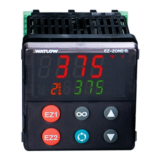
Chapter 3: Keys and Displays 1/32 DIN (PM3) Lower (Right, 32 DIN) Upper (Left, 32 DIN) Dis- Display: play: ® Indicates the set point or In the Home Page, displays the Manual Power value during process value, otherwise dis- operation, or the param- plays the value of the param- eter whose value appears eter in the lower display. -
Page 39: Responding To A Displayed Message
Responding to a Displayed Message An active message will cause the display to toggle between the normal settings and the ac- tive message in the upper display and in the lower display. attn Your response will depend on the message and the controller settings. Some messages, such as Ramping and Tuning, indicate that a process is underway. -
Page 40: Chapter 4: Home Page
Chapter 4: Home Page Default Home Page Parameters Watlow's patented user-defined menu system improves operational efficiency. The user- defined Home Page provides you with a shortcut to monitor or change the parameter values that you use most often. The default Home Page is shown on the following page. When a pa- rameter normally located in the Setup Page or Operations Page is placed in the Home Page, it is accessible through both. -
Page 41: Navigating The Ez-Zone ® Pm Pid Controller
® Navigating the EZ-ZONE PM PID Controller Applies to All Models - 1/16 DIN Shown Below ® ® ® ® [``Ai] [``70] [``70] [Cust] [``72] [fCty] [`Set] [``72] Home Page from anywhere: Press the Infinity Factory Page from Home Page: Press both for two seconds to return to the Home the Advance and Infinity... -
Page 42: Starting A Profile From The Home Page
Starting a Profile from the Home Page 1. When at the Home Page, press the Advance Key to locate Profile Start and select the ‰ file or step number to start. The upper display will show and the lower display will show p. - Page 43 Custom Menu Parameter Options Description Prompt * Closed Loop Timer Set Point Ct. S p Hours hoUr Minutes ЛЏin Seconds If 4 digit of part number is B, E, C, R, J, or N Set Point C. s p1 Active Process Value AC.
-
Page 44: Modifying The Display Pairs
Modifying the Display Pairs The Home Page, being a customized list of as many as 20 parameters, can be configured in pairs of up to 10 via the Display Pairs prompt found in the Global Menu (Setup gLbL d. p rs Page). -
Page 45: Conventions Used In The Menu
Possible Home Page Home Page Defaults Parameter Page and Menu Display (Dependent on Part Number) If 4 digit of part number is equal to: PM _ [T] _ _ _ - _ _ _ _ _ _ _ Set Point (1) Numerical value Operations Page, Monitor Menu Ready State Band (1) -
Page 46: Display
360 (low order bytes) and 361 (high order bytes). Because the Modbus specification does not dictate which register should be high or low order, Watlow provides the user the ability to swap this order (Setup Page, Menu) from the default low/high to high/low CoЛЏ... - Page 47 To learn more about the RUI/GTW point your browser to the link below and search for key- word gateway. http://www.watlow.com/en/Resources-And-Support/Technical-Library/User-Manuals Wa t low EZ-ZO N E ® P M P ID Co n t r o l le r Chapter 4 Home Pa ge •...
-
Page 48: Chapter 5: Operations Page
Chapter 5: Operations Page PM Operation Page Parameters To navigate to the Operations Page, follow the steps below: 1. From the Home Page, press both the Up ¿ and Down ¯ keys for three seconds. will ap- pear in the upper display and will appear in the lower display. - Page 49 Loop P. s ta opEr Loop Menu opEr Profile Status Menu Control Mode Profile Start C. Л Џ P. s tr Autotune Set Point Profile Action Request A. t sp paCr Autotune Current Step Closed Loop Set Point Step Type C.
-
Page 50: Analog Input Menu
Operations Page Data Type Modbus Class Pro- Param- Parameter Name Display Range Default Relative Ad- Instance fibus eter Description dress Attribute Index cess hex (dec) opEr Analog Input Menu - - - - float Analog Input -1,999.000 to Instance 1 0x68 4001 Analog Input Value... -
Page 51: Linearization Menu
Operations Page Data Type Modbus Class Pro- Param- Parameter Name Display Range Default Relative Ad- Instance fibus eter Description dress Attribute Index cess hex (dec) opEr Linearization Menu - - - - float Su. a Linearization -1,999.000 to Instance 1 0x86 - - - - 34004 Map 1 Map 2... -
Page 52: Process Value Menu
Operations Page Data Type Modbus Class Pro- Param- Parameter Name Display Range Default Relative Ad- Instance fibus eter Description dress Attribute Index cess hex (dec) opEr Process Value Menu - - - - float Su. a Process Value -1,999.000 to Instance 1 0x7E - - - - 26016... -
Page 53: Monitor Menu
Operations Page Data Type Modbus Class Pro- Param- Parameter Name Display Range Default Relative Ad- Instance fibus eter Description dress Attribute Index cess hex (dec) - - - - uint di. s Digital Input (5 to 6) Instance 5 0x6A - - - - 6011 Off (62) Input State... -
Page 54: Control Loop Menu
Operations Page Data Type Modbus Class Pro- Param- Parameter Name Display Range Default Relative Ad- Instance fibus eter Description dress Attribute Index cess hex (dec) No Dis- - - - - float Monitor -1,999.000 to Instance 1 0x6B - - - - 8031 play Set Point Active... - Page 55 Operations Page Data Type Modbus Class Pro- Param- Parameter Name Display Range Default Relative Ad- Instance fibus eter Description dress Attribute Index cess hex (dec) uint Control Loop Instance 1 0x97 8026 No (59) Autotune Map 1 Map 2 (151) Yes (106) Start an autotune.
- Page 56 Operations Page Data Type Modbus Class Pro- Param- Parameter Name Display Range Default Relative Ad- Instance fibus eter Description dress Attribute Index cess hex (dec) 3.0°F float C. h y Control Loop 0.001 to Instance 1 0x97 8013 or units RWES On/Off Cool Hysteresis 9,999.000°F or...
-
Page 57: Alarm Menu
Operations Page Data Type Modbus Class Pro- Param- Parameter Name Display Range Default Relative Ad- Instance fibus eter Description dress Attribute Index cess hex (dec) No Dis- - - - - float Control Loop -100.0 to 100.0 Instance 1 0x97 - - - - 8033 play... - Page 58 Operations Page Data Type Modbus Class Pro- Param- Parameter Name Display Range Default Relative Ad- Instance fibus eter Description dress Attribute Index cess hex (dec) - - - - uint A. C Lr Alarm (1 to 4) Instance 1 0x6D - - - - 9026 Clear (1003) Clear Alarm...
-
Page 59: Timer Menu
Operations Page Data Type Modbus Class Pro- Param- Parameter Name Display Range Default Relative Ad- Instance fibus eter Description dress Attribute Index cess hex (dec) No Dis- - - - - uint Alarm (1 to 4) No (59) Instance 1 0x6D - - - - 9010... - Page 60 Operations Page Data Type Modbus Class Pro- Param- Parameter Name Display Range Default Relative Ad- Instance fibus eter Description dress Attribute Index cess hex (dec) t. r Timer Instance 1 0x83 - - - - 31021 string 00. 0 0 00:00 to Time Remaining (131)
-
Page 61: Profile Status Menu
Operations Page Data Type Modbus Class Pro- Param- Parameter Name Display Range Default Relative Ad- Instance fibus eter Description dress Attribute Index cess hex (dec) No Dis- - - - - Timer Off (62) Instance 1 0x83 - - - - 31042 uint play... - Page 62 Operations Page Data Type Modbus Class Pro- Param- Parameter Name Display Range Default Relative Ad- Instance fibus eter Description dress Attribute Index cess hex (dec) - - - - s. t yp Profile Status Instance 1 0x7A - - - - 22013 uint Ustp Unused...
- Page 63 Operations Page Data Type Modbus Class Pro- Param- Parameter Name Display Range Default Relative Ad- Instance fibus eter Description dress Attribute Index cess hex (dec) ЛЏin Profile Status 0 to 59 Instance 1 0x7A - - - - 22077 uint Minutes Map 1 Map 2 (122)
-
Page 64: Chapter 6: Setup Page
Chapter 6: Setup Page Navigating the Setup Page To navigate to the Setup Page follow the steps below: 1. From the Home Page, press and hold both the Up ¿ and Down ¯ keys for six seconds. will appear in the upper display and will appear in the lower display. - Page 65 Output Point 3 Maximum Manual op. 3 Loop SP. h i Power Input Point 4 ip. 4 Control Loop Menu Manual Power * o. s p Output Point 4 op. 4 Heat Algorithm h. a g Control Mode * C. Л Џ Input Point 5 ip.
- Page 66 Silence Alarm * Communications LED a. s ir C. L Ed Action Alarm State * a. s t Zone 2onE tЛЏr Channel Chan Timer Menu Display Pairs d. p rs Timer Enable ti. E n Display Time d. t i Timer Start Method ti.
-
Page 67: Analog Input Menu
Setup Page CIP - Data Modbus Class Pro- Param- Type Parameter Name Display Range Default Relative Ad- Instance fibus eter Description dress Attribute Index Access hex (dec) Analog Input Menu Analog Input Thermo- Instance 1 0x68 4005 uint Off (62) Sensor Type couple or Map 1 Map 2... - Page 68 Setup Page CIP - Data Modbus Class Pro- Param- Type Parameter Name Display Range Default Relative Ad- Instance fibus eter Description dress Attribute Index Access hex (dec) Analog Input -100.00 to 1,000.00 Instance 1 0x68 4015 float s. L o Scale Low Map 1 Map 2 (104)
- Page 69 Setup Page CIP - Data Modbus Class Pro- Param- Type Parameter Name Display Range Default Relative Ad- Instance fibus eter Description dress Attribute Index Access hex (dec) Analog Input Curve A Instance 1 0x68 - - - - 4038 uint t.
-
Page 70: Linearization Menu
Setup Page CIP - Data Modbus Class Pro- Param- Type Parameter Name Display Range Default Relative Ad- Instance fibus eter Description dress Attribute Index Access hex (dec) Analog Input -1,999.000 to - - - - Instance 1 0x68 4001 float Analog Input Value 9,999.000°F or units Map 1 Map 2... - Page 71 Setup Page CIP - Data Modbus Class Pro- Param- Type Parameter Name Display Range Default Relative Ad- Instance fibus eter Description dress Attribute Index Access hex (dec) Linearization Source Instance 1 0x86 34029 uint Unit Source (1539) Units Map 1 Map 2 (134) RWES Unit...
- Page 72 Setup Page CIP - Data Modbus Class Pro- Param- Type Parameter Name Display Range Default Relative Ad- Instance fibus eter Description dress Attribute Index Access hex (dec) Linearization -1,999.000 to Instance 1 0x86 34021 float op. 4 Output Point 4 9,999.000 Map 1 Map 2 (134)
-
Page 73: Process Value Menu
Setup Page CIP - Data Modbus Class Pro- Param- Type Parameter Name Display Range Default Relative Ad- Instance fibus eter Description dress Attribute Index Access hex (dec) Linearization -1,999.000 to Instance 1 0x86 34016 float ip. q Input Point 9 9,999.000 Map 1 Map 2 (134) -
Page 74: Digital Input/Output Menu
Setup Page CIP - Data Modbus Class Pro- Param- Type Parameter Name Display Range Default Relative Ad- Instance fibus eter Description dress Attribute Index Access hex (dec) Process Value Instance 1 0x7E - - - - 26029 uint a. u nt Kilofeet (1677) Altitude Units*** Map 1 Map 2... - Page 75 Setup Page CIP - Data Modbus Class Pro- Param- Type Parameter Name Display Range Default Relative Ad- Instance fibus eter Description dress Attribute Index Access hex (dec) Digital Output (5 Instance 5 0x 6A 6005 uint Off (62) to 6) Map 1 Map 2 (106) RWES...
- Page 76 Setup Page CIP - Data Modbus Class Pro- Param- Type Parameter Name Display Range Default Relative Ad- Instance fibus eter Description dress Attribute Index Access hex (dec) Digital Output (5 0.0 to 100.0% Instance 5 0x6A 6009 float o. L o to 6) Map 1 Map 2 (106)
- Page 77 Setup Page CIP - Data Modbus Class Pro- Param- Type Parameter Name Display Range Default Relative Ad- Instance fibus eter Description dress Attribute Index Access hex (dec) Digital Input (5 to 6) None Instance 5 0x6E 10003 uint nonE None (61) Action Function Map 1 Map 2 (110)
-
Page 78: Control Loop Menu
Setup Page CIP - Data Modbus Class Pro- Param- Type Parameter Name Display Range Default Relative Ad- Instance fibus eter Description dress Attribute Index Access hex (dec) Digital Input (5 to 6) 0 to 40 Instance 5 0x6E 10004 uint Function Instance Map 1 Map 2 (110) - Page 79 Setup Page CIP - Data Modbus Class Pro- Param- Type Parameter Name Display Range Default Relative Ad- Instance fibus eter Description dress Attribute Index Access hex (dec) Control Loop 0.001 to 9,999.000°F 25.0°F Instance 1 0x97 8012 float C. p b Cool Proportional or units or units...
- Page 80 Setup Page CIP - Data Modbus Class Pro- Param- Type Parameter Name Display Range Default Relative Ad- Instance fibus eter Description dress Attribute Index Access hex (dec) Control Loop Instance 1 0x97 - - - - 8022 uint t. t Un No (59) TRU-TUNE+ ®...
- Page 81 Setup Page CIP - Data Modbus Class Pro- Param- Type Parameter Name Display Range Default Relative Ad- Instance fibus eter Description dress Attribute Index Access hex (dec) Control Loop 0.0 to 5.0 seconds Instance 1 0x97 - - - - 8051 float p.
- Page 82 Setup Page CIP - Data Modbus Class Pro- Param- Type Parameter Name Display Range Default Relative Ad- Instance fibus eter Description dress Attribute Index Access hex (dec) Control Loop Set Point Open Loop Instance 1 0x6B - - - - 7011 float ЛЏan...
- Page 83 Setup Page CIP - Data Modbus Class Pro- Param- Type Parameter Name Display Range Default Relative Ad- Instance fibus eter Description dress Attribute Index Access hex (dec) Control Loop -1,999.000 to 10.0°F or Instance 1 0x97 8041 float L. d d Open Loop Detect 9,999.000°F or units units...
- Page 84 Setup Page CIP - Data Modbus Class Pro- Param- Type Parameter Name Display Range Default Relative Ad- Instance fibus eter Description dress Attribute Index Access hex (dec) Control Loop -1,999.000 to 75.0°F Instance 1 0x6B 7009 float id. s Idle Set Point * 9,999.000°F or units or units Map 1 Map 2...
-
Page 85: Output Menu
Setup Page CIP - Data Modbus Class Pro- Param- Type Parameter Name Display Range Default Relative Ad- Instance fibus eter Description dress Attribute Index Access hex (dec) otpt Output Menu Output Digital (1 Output 1 Instance 1 0x6A 6005 uint Off (62) to 2) - Heat... - Page 86 Setup Page CIP - Data Modbus Class Pro- Param- Type Parameter Name Display Range Default Relative Ad- Instance fibus eter Description dress Attribute Index Access hex (dec) Output Digital (1 0.0 to 100.0% 0.0% Instance 1 0x6A 6009 float o. L o to 2) Map 1 Map 2 (106)
- Page 87 Setup Page CIP - Data Modbus Class Pro- Param- Type Parameter Name Display Range Default Relative Ad- Instance fibus eter Description dress Attribute Index Access hex (dec) Output Process (1) 1 to 4 Instance 1 0x76 18004 uint Function Instance Map 1 Map 2 (118) RWES...
-
Page 88: Alarm Menu
Setup Page CIP - Data Modbus Class Pro- Param- Type Parameter Name Display Range Default Relative Ad- Instance fibus eter Description dress Attribute Index Access hex (dec) Output Process (1) -1,999.000 to 100.0°F Instance 1 0x76 18012 float r. h i Range High 9,999.000°F or units or units... - Page 89 Setup Page CIP - Data Modbus Class Pro- Param- Type Parameter Name Display Range Default Relative Ad- Instance fibus eter Description dress Attribute Index Access hex (dec) Alarm (1 to 4) 0.001 to 9,999.000°F 1.0°F or Instance 1 0x6D 9003 float A.
- Page 90 Setup Page CIP - Data Modbus Class Pro- Param- Type Parameter Name Display Range Default Relative Ad- Instance fibus eter Description dress Attribute Index Access hex (dec) Alarm (1 to 4) -1,999.000 to 32.0°F Instance 1 0x6D 9002 float A. L o Low Set Point 9,999.000°F or or units...
- Page 91 Setup Page CIP - Data Modbus Class Pro- Param- Type Parameter Name Display Range Default Relative Ad- Instance fibus eter Description dress Attribute Index Access hex (dec) Alarm (1 to 4) Non- Instance 1 0x6D 9007 uint A. L A nLAt Non-Latching Latching...
- Page 92 Setup Page CIP - Data Modbus Class Pro- Param- Type Parameter Name Display Range Default Relative Ad- Instance fibus eter Description dress Attribute Index Access hex (dec) Alarm (1 to 4) 0 to 9,999 seconds Instance 1 0x6D 9021 uint A.
-
Page 93: Timer Menu
Setup Page CIP - Data Modbus Class Pro- Param- Type Parameter Name Display Range Default Relative Ad- Instance fibus eter Description dress Attribute Index Access hex (dec) tЛЏr Timer Menu Timer (1) Instance 1 0x83 - - - - 31029 uint ti. - Page 94 Setup Page CIP - Data Modbus Class Pro- Param- Type Parameter Name Display Range Default Relative Ad- Instance fibus eter Description dress Attribute Index Access hex (dec) Timer (1) 1 to 24 Instance 1 0x83 - - - - 31034 uint Si.
-
Page 95: Function Key
Setup Page CIP - Data Modbus Class Pro- Param- Type Parameter Name Display Range Default Relative Ad- Instance fibus eter Description dress Attribute Index Access hex (dec) Timer (1) -1999.000 to Instance 1 0x83 - - - - 31028 float Ct. - Page 96 Setup Page CIP - Data Modbus Class Pro- Param- Type Parameter Name Display Range Default Relative Ad- Instance fibus eter Description dress Attribute Index Access hex (dec) Function Key (1 to None Instance 1 0x6E 10003 uint nonE None (61) Map 1 Map 2 (110) RWES...
-
Page 97: Global Menu
Setup Page CIP - Data Modbus Class Pro- Param- Type Parameter Name Display Range Default Relative Ad- Instance fibus eter Description dress Attribute Index Access hex (dec) Function Key (1 to 0 to 40 Instance 1 0x96 10004 - - - - Map 1 Map 2 (110) 1366... - Page 98 Setup Page CIP - Data Modbus Class Pro- Param- Type Parameter Name Display Range Default Relative Ad- Instance fibus eter Description dress Attribute Index Access hex (dec) Global 0.0 to 9,999.000°F or 10.0°F or Instance 1 0x7A - - - - 22007 float gSd1 Guaranteed Soak units...
- Page 99 Setup Page CIP - Data Modbus Class Pro- Param- Type Parameter Name Display Range Default Relative Ad- Instance fibus eter Description dress Attribute Index Access hex (dec) Global Comm Instance 1 0x6A - - - - 3014 uint C. L Ed Con1 Comm port 1 Communications...
-
Page 100: Communications Menu
Setup Page CIP - Data Modbus Class Pro- Param- Type Parameter Name Display Range Default Relative Ad- Instance fibus eter Description dress Attribute Index Access hex (dec) CoЛЏ Communications Menu Communications Modbus Instance 1 0x96 - - - - 17009 uint PCoL Standard Bus Protocol... - Page 101 Setup Page CIP - Data Modbus Class Pro- Param- Type Parameter Name Display Range Default Relative Ad- Instance fibus eter Description dress Attribute Index Access hex (dec) Communications None Instance 1 0x96 - - - - 17003 uint nonE None (61) Parity Map 1 Map 2 (150)
-
Page 102: Real Time Clock Menu
Setup Page CIP - Data Modbus Class Pro- Param- Type Parameter Name Display Range Default Relative Ad- Instance fibus eter Description dress Attribute Index Access hex (dec) Real Time Clock Menu Real Time Clock 0 to 23 Instance 1 88 (136) - - - - 36003 uint hoUr Hours... -
Page 103: Chapter 7: Profiling Page
Chapter 7: Profiling Page Navigating the Profiling Page Note: Some of these menus and parameters may not appear, depending on the controller's op- tions. See model number information in the Appendix for more information. If there is only one instance of a menu, no submenus will appear. Profile Setup First, consider some foundational profile setup features that once configured, will apply to all configured profiles. - Page 104 Once these global profile features are configured, the next step will require navigation to the Profiling Page. Here, each desired ramp and soak profile will be configured. To navigate to the Profile Page from the front panel, follow the steps below: 1.
- Page 105 Configuring the Function Key to Start and Stop a Profile 1. Navigate to the Setup Page and then the Function menu. From the Home Page, press and hold the or Down key for approximately six seconds where the upper display will ¿...
- Page 106 3. Press the Advance Key to enter this menu. The upper display will show and the lower ‰ display will show p. s tr 4. Press the Up or Down keys to select the Profile or Step to start. In this example se- ¿...
- Page 107 Starting a Profile from the Home Page 1. When at the Home Page, press the Advance Key to locate Profile Start and select the ‰ file or step number to start. The upper display will show and the lower display will show p.
-
Page 108: Profiling Menu
Profiling Page Data Modbus Class Type Parameter Name ram- Display Range Default Relative Instance Description eter Address Attribute Access hex (dec) prof Profiling Menu Profile [1 to 4] Step 1 to 10 [profile 1] - - - - - - - - - - - - - - - - 11 to 20 [profile 2]... - Page 109 Profiling Page Data Modbus Class Type Parameter Name ram- Display Range Default Relative Instance Description eter Address Attribute Access hex (dec) 0 to 9999 Step Type Parameters Instance 1 0x79 (121) 21003 uint hoUr Hours Map 1 Map 2 1 to 40 hoUr Select the hours (plus Min- 2574...
- Page 110 Profiling Page Data Modbus Class Type Parameter Name ram- Display Range Default Relative Instance Description eter Address Attribute Access hex (dec) -1,999.000 to Step Type Parameters 0.0°F or Instance 1 0x79 (121) 21011 float ФІ. P 1 Wait For Process 1 9,999.000°F or units Map 1 Map 2...
- Page 111 Profiling Page Data Modbus Class Type Parameter Name ram- Display Range Default Relative Instance Description eter Address Attribute Access hex (dec) Step Type Parameters Sunday Instance 1 0x79 (121) 21041 uint doФІ Every Day (1567) Day of Week Map 1 Map 2 1 to 40 ФІd Week days...
- Page 112 Profiling Page Data Modbus Class Type Parameter Name ram- Display Range Default Relative Instance Description eter Address Attribute Access hex (dec) Step Type Parameters Instance 1 0x79 (121) 21007 uint Ent1 Off (62) Event 1 Map 1 Map 2 1 to 40 On (63) Ent1 When Step Type is not Un-...
- Page 113 Display Step Type Description Parameters in Step Type Step Types SoAH hoUr Hours Soak ЛЏin Minutes SoAh A Soak Step maintains the last Target Set Points for the desig- Seconds nated time. The state of up to 2 event outputs may be set or Ent1 Event 1 maintained.
-
Page 114: Chapter 8: Factory Page
Chapter 8: Factory Page Navigating the Factory Page To navigate to the Factory Page follow the steps below: 1. From the Home Page, press and hold both the Advance and Infinity ˆ keys for six sec- ‰ onds. 2. Press the Up ¿ or Down ¯ key to view available menus. 3. -
Page 115: Custom
Factory Page Class Data Modbus Instance Pro- Param- Type Parameter Name Display Range Default Relative Ad- Attri- fibus eter Description dress bute Index Access (dec) Cust fcty Custom Custom See: None - - - - - - - - - - - - 14005 uint nonE Parameter 1 to Home... -
Page 116: Lock Menu
Factory Page Class Data Modbus Instance Pro- Param- Type Parameter Name Display Range Default Relative Ad- Attri- fibus eter Description dress bute Index Access (dec) Custom (1 to 20) 1 to 4 - - - - - - - - - - - - 14003 uint Instance ID RWES... - Page 117 Factory Page Class Data Modbus Instance Pro- Param- Type Parameter Name Display Range Default Relative Ad- Attri- fibus eter Description dress bute Index Access (dec) Security Setting 1 to 5 Instance 1 0x67 - - - - 3010 uint rLoC Read Lock Map 1 Map 2...
-
Page 118: Unlock Menu
Factory Page Class Data Modbus Instance Pro- Param- Type Parameter Name Display Range Default Relative Ad- Attri- fibus eter Description dress bute Index Access (dec) Security Setting - - - - - - - - - - - - 3019 uint roLL Rolling Password... -
Page 119: Diagnostics Menu
Factory Page Class Data Modbus Instance Pro- Param- Type Parameter Name Display Range Default Relative Ad- Attri- fibus eter Description dress bute Index Access (dec) Security Setting -1999 to 9999 - - - - - - - - - - - - 3022 pass Password PASS... -
Page 120: Calibration Menu
Factory Page Class Data Modbus Instance Pro- Param- Type Parameter Name Display Range Default Relative Ad- Attri- fibus eter Description dress bute Index Access (dec) Diagnostics 0 to 2,147,483,647 - - - - Instance 1 0x65 1008 dint dAtE Date of Manu- Map 1 Map 2 (101) dAtE... - Page 121 Factory Page Class Data Modbus Instance Pro- Param- Type Parameter Name Display Range Default Relative Ad- Attri- fibus eter Description dress bute Index Access (dec) Calibration (1 -1,999.000 to 9,999.000 Instance 1 0x68 4010 float ELi. o to 2) Map 1 Map 2 (104) RWES ELi.o...
- Page 122 Factory Page Class Data Modbus Instance Pro- Param- Type Parameter Name Display Range Default Relative Ad- Attri- fibus eter Description dress bute Index Access (dec) Calibration (1 4999 - - - - - - - - - - - - uint CodE 2501...
-
Page 123: Chapter 9: Features
Chapter 9: Features Changing PM Integrated Model Number to PM Express . . . . . . 121 Saving and Restoring Settings . . . . . . . . . . . . . . . . . . . . . . . 122 Programming the Home Page . - Page 124 Chapter 9: Features (cont .) Blocking . . . . . . . . . . . . . . . . . . . . . . . . . . . . . . . . . . . . . . . . . . . . . . . . 141 Open Loop Detection .
-
Page 125: Changing Pm Integrated Model Number To Pm Express
Changing PM Integrated Model Number to PM Express EZ-ZONE PM firmware revisions of 13 and above allow the user to switch between a PM Inte- grated control to a PM Express. Switching to a PM Express eliminates the complexity of the advanced PM Integrated control by allowing the user to operate with a simplified menu struc- ture. -
Page 126: Saving And Restoring Settings
After switching the model number to a PM Express this document will no longer apply to the control. Click on the link that follows to acquire the latest version of the PM PID Ex- press User's Guide. http://www.watlow.com/en/Resources-And-Support/Technical-Library/ User-Manuals Once there, simply enter express in the "Keyword" field to find the appropriate document. -
Page 127: Programming The Home Page
Time no affect. A new feature in EZ-ZONE PM products will allow set point changes while the control is auto- tuning, this includes while running a profile or ramping. When the auto tune is initially start- ed it will use the current set point and will disregard all set point changes until the tuning Wat lo w EZ-ZO N E ®... -
Page 128: Manual Tuning
process is complete. Once complete, the controller will then use the new set point. This is why it is a good idea to enter the active set point before initiating an autotune. Autotuning calculates the optimum heating and/or cooling PID parameter settings based on ®... -
Page 129: Autotuning With Tru-Tune
Autotuning with TRU-TUNE+ ® The TRU-TUNE+ adaptive algorithm will optimize the controller's PID values to improve con- trol of dynamic processes. TRU-TUNE+ monitors the Process Value and adjusts the control pa- rameters automatically to keep your process at set point during set point and load changes. When the controller is in the adaptive control mode, it determines the appropriate output signal and, over time, adjusts control parameters to optimize responsiveness and stability. -
Page 130: Inputs
When autotuning is complete, the PID parameters should provide good control. As long as the loop is in the adaptive control mode, TRU-TUNE+ continuously tunes to provide the best pos- sible PID control for the process. ç WARNING! During autotuning, the controller sets the output to 100 percent and attempts to drive the Process Value toward the set point. - Page 131 Calibration of Analog Inputs: To calibrate an analog input, you will need to provide a source of two electrical signals or resistance values near the extremes of the range that the application is likely to utilize. See recommended values below: Sensor Type Precision Source Low Precision Source High...
-
Page 132: Filter Time Constant
12. Calculated Electrical Input Offset = Precision Low - (Electrical Input Slope * Measured Low) Calculated Offset value ___________ 13. Enter the calculated Electrical Input Slope and Electrical Input Offset into ELi. s ELi. o the controller. 14. Exit calibration menu. 15. -
Page 133: Range High And Range Low
You can create a scale range representing other units for special applications. You can re- verse scales from high values to low values for analog input signals that have a reversed ac- tion. For example, if 50 psi causes a 4 mA signal and 10 psi causes a 20 mA signal. Scale low and high low values do not have to match the bounds of the measurement range. -
Page 134: No-Arc Relay
12 to 4mA (0 to -100 percent). In some cases this type of output is required by the device that the EZ-ZONE PM controls, such as a three-way valve that opens one way with a 12 to 20mA signal and opens the other way with a 4 to 12mA signal. -
Page 135: Cool Output Curve
In choosing the type of retransmit signal the operator must take into account the input impedance of the device to be Retransmit retransmitted to and the required Range High signal type, either voltage or milli- amps. Typically applications might use the retransmit option to record one of the variables with a chart recorder or to generate a set point for other controls in a multi-zone... -
Page 136: Auto (Closed Loop) And Manual (Open Loop) Control
Auto (closed loop) and Manual (open loop) Control The controller has two basic modes of operation, auto mode and manual mode. Auto mode allows the controller to decide whether to perform closed-loop control or to follow the settings of Input Error Failure (Setup Page, Loop Menu). -
Page 137: On-Off Control
To transfer to manual mode from auto mode: 1. Press the Advance Key until appears in the lower display. The upper display will C. Л Џ ‰ display for auto mode. aUto 2. Use the Up or Down keys to select ЛЏan. The manual set point value will be re- ¿... -
Page 138: Proportional And Integral (Pi) Control
This is similar to backing off on the gas pedal of a car as you approach a stop sign. It keeps the temperature or process value from swing- Proportional Control ing as widely as it would with simple on-off Overshoot Set Point control. -
Page 139: Variable Time Base
continues to bring the process temperature to the set point. Using a positive dead band value keeps the two systems from fighting each other. Positive Dead Band Cool Output Active Set Point Heat Output Active Time When the dead band value is zero, the heating output activates when the temperature drops below the set point, and the cooling output switches on when the temperature ex- ceeds the set point. -
Page 140: Single Set Point Ramping
fire) device, such as a solid-state power controller, switching is done only at the zero cross of the ac line, which helps reduce electrical noise (RFI). Variable time base should be used with solid-state power controllers, such as a solid-state relay (SSR) or silicon controlled rectifier (SCR) power controller. -
Page 141: Timer Function
Timer Function 1. When Timer Enable is set to yes and the timer is started (you define which key ti. E n combination this is), the controller will switch from Set Point to Closed Loop Timer C. s p1 Set Point . -
Page 142: Setting Up The Timer Function
Setting Up the Timer Function 1. Press and hold up ¿ and down ¯ arrow keys for 6 seconds to enter into the Setup Page 2. Up arrow ¿ to Timer Menu tЛЏr 3. Advance to Timer Enable to make selection using the up ¿ and down ¯ arrow ti. - Page 143 10. Advance to Source Function D to select which input will acknowledge the ready sfn. d ‰ band. Use the up arrow ¿ to select from the options below: None nonE Digital I/O Function Key 11. Advance to Source Instance D and use the up arrow ¿ to make a selection below: ‰...
-
Page 144: Alarms
Alarms Alarms are activated when the output level, process value or temperature leaves a defined range. A user can configure how and when an alarm is triggered, what action it takes and whether it turns off automatically when the alarm condition is over. Configure alarm outputs in the Setup Page before setting alarm set points. -
Page 145: Latching
The process temperature has to enter the normal operating range beyond the hysteresis zone to activate the alarm function. If the EZ-ZONE PM has an output that is functioning as a deviation alarm, the alarm is blocked when the set point is changed, until the process value re-enters the normal operating range. -
Page 146: Using Lockout And Password Security
Loop message will be display. If the process value goes in the opposite direction, a Reversed Loop message is display. The sensor is likely wired in reverse polarity. Note: All prompts identified in this section can be found in the Loop Menu of the Setup Page. Using Lockout and Password Security If unintentional changes to parameter settings might raise safety concerns or lead to down- time, you can use the lockout feature to make them more secure. - Page 147 Changing Security Levels: 1. From the Home Page, press and hold the Infinity Key and the Advance Key for ap- ˆ ‰ proximately six seconds. will appear in the upper display and will appear in the CUst fCty lower display. 2.
-
Page 148: Using Lockout Method 2 (Password Enable)
* Using lockout Method 1 with set to 0, all writable parameters within the control SLoC will be inhibited (not writable) with two exceptions, . As shown below, SLoC rLoC both of these parameters can always be seen and modified. ** Diagnostic Menu and all associated prompts are always visible and never writable Lockout Security sLoC... - Page 149 The Administrator can either change the User and or the Administrator password or leave them in the default state. Once Password Security is enabled they will no longer be visible to anyone other than the Administrator. In other words the Lock Menu is not available to a User.
-
Page 150: Modbus - Using Programmable Memory Blocks
An Administrator is restricted according to the Read Lockout Security however, the rLoC Administrator has access to the Lock Menu where the Read Lockout can be changed. Modbus - Using Programmable Memory Blocks When using the Modbus RTU or Modbus TCP protocols, the PM control features a block of ad- dresses that can be configured by the user to provide direct access to a list of 40 user config- ured parameters. -
Page 151: Software Configuration
3. Navigate to the "Watlow" folder and then the sub-folder "EZ-ZONE Configurator" 4. Click on EZ-ZONE Configurator to run. The first screen that will appear is shown below. If the PC is already physically connected to the EZ-ZONE PM control click the next button to go on-line. Note: When establishing communications from PC to the EZ-ZONE PM control an interface con- verter will be required. - Page 152 After clicking the next button above it is necessary to define the communications port that will be used on the PC as shown below. Clicking on the drop down will allow the user to select the appropriate communications port. This will be the port assigned to the EIA-485 to USB converter when it was connected to the PC.
- Page 153 The menu structure as laid out within this software follows: - Setup - Operations - Factory - Profile Navigating from one menu to the next is easy and clearly visible. Simply slide the scroll bar up or down to display the menu and parameter of choice. If there is a need to bring greater focus and clarity to the parameters of interest simply click on the negative symbol next to any of the Menu items.
- Page 154 (saved in) and enter the file name (File name) as well. The default path for saved files follows: Users\"Username"\My Documents\Watlow\EZ-Zone Configurator\Saved Configurations The user can save the file to any folder of choice. Wat lo w EZ-ZO NE ®...
-
Page 155: Chapter 10: Appendix
Chapter 10: Appendix Troubleshooting Alarms, Errors and Control Issues Indication Description Possible Cause(s) Corrective Action Alarm won’t Alarm will not clear • Latching is active • Reset alarm when process clear or reset or reset with keypad is within range or disable or digital input latching •... - Page 156 Indication Description Possible Cause(s) Corrective Action Alarm Low Sensor input below • Temperature is less than • Check cause of under low alarm set point alarm set point temperature AL. L 1 AL. L 2 • Alarm is set to latching •...
- Page 157 Indication Description Possible Cause(s) Corrective Action Loop Reversed Open Loop Detect is • Setting of Open Loop De- • Set correct Open Loop Error active and the pro- tect Time incorrect Detect Time for applica- cess value is head- tion Lp.
- Page 158 Indication Description Possible Cause(s) Corrective Action No Display No display indica- • Power to controller is off • Turn on power tion or LED illumi- • Fuse open • Replace fuse nation • Breaker tripped • Reset breaker • Safety interlock switch •...
- Page 159 Indication Description Possible Cause(s) Corrective Action Temperature Process value con- • Controller output incor- • Verify output function is runway tinues to increase rectly programmed correct (heat or cool) or decrease past set • Thermocouple reverse • Correct sensor wiring point.
- Page 160 Detection of and Rules Around Abnormal Sensor Conditions Inputs Detection of Abnormal Conditions Thermocouple Shorted No direct detection, Open loop firmware detection. Open Yes, Parasitic pull-up Reversed Yes, firmware detection Current Source Shorted Range limiting only Open Range limiting only Reversed Range limiting only Voltage Source...
-
Page 161: Modbus - Programmable Memory Blocks
The screen shot above was taken from a program that can be found on the Watlow Support Tools DVD (shipped with the product) as well as on the Watlow website. On the DVD, it can be found under "Utility Tools" and is identified as "Modbus RTU Diagnostic Program for EZ- ZONE PM, RM and ST". - Page 162 Assembly Definition Addresses and Assembly Working Addresses Pointer Registers Working Registers 40 & 41 200 & 201 42 & 43 202 & 203 44 & 45 204 & 205 46 & 47 206 & 207 48 & 49 208 & 209 50 &...
- Page 163 Modbus Default Assembly Structure 40-119 Assembly Pointer Assembly Working Assembly Working Assembly Pointer Registers Addresses Registers Addresses Registers 80 & 81 Registers 240 & 241 Registers 40 & 41 Registers 200 & 201 Pointer 21 = 360 & 361 Value of Pointer 21 Analog Input 1 Pointer 1 = 1880 &...
-
Page 164: Pm Specifications
PM Specifications LineVoltage/Power (Minimum/Maximum Ratings) • 85 to 264VÅ (ac), 47 to 63Hz • 20 to 28VÅ (ac), 47 to 63Hz • 12 to 40VÎ (dc) • 14VA maximum power consumption (PM4, 8 & 9) • 10VA maximum power consumption (PM6) •... - Page 165 Isolated Serial Communications • EIA232/485, Modbus ® Wiring Termination—Touch-Safe Terminals • Input, power and controller output terminals are touch safe removable 3.30 to 0.0507 mm (12 to 22 AWG) • Wire strip length 7.6 mm (0.30 in.) • Torque 0.56 Nm (5.0 in-lb) Universal Input •...
- Page 166 Accuracy Accuracy Input Type Max Error @ 25 Deg C Units Range Low Range High Volts ±0.01 Volts mAdc ±0.02 mAmps DC mAac ±5 mAmps AC Operating Range Input Type Range Low Range High Units -210 1200 Deg C -270 1371 Deg C -270...
- Page 167 Alpha Beta Thermistor Base R @ 25C Techniques THERM Curve 2.252K Curve A 2.2K3A Curve A 10K3A Curve C 10K4A 2 Digital Input/Output Option - 2 DIO • Digital input update rate 10Hz - DC voltage - Max. input 36V @ 3mA - Min.
- Page 168 • Electromechanical relay, Form C, 5A, 24 to 240VÅ (ac) or 30VÎ (dc) max., resistive load, 100,000 cycles at rated load, 125 VA pilot duty at 120/240VÅ (ac), 25 VA at 24VÅ (ac) • Electromechanical relay, FormA, 5A, 24 to 240VÅ (ac) or 30VÎ (dc) max., resistive load, 100,000 cycles at rated load, 125 VA pilot duty at 120/240VÅ...
- Page 169 Weight 1/32 DIN (PM3) 1/4 DIN (PM4) • Controller: 127 g (4.5 oz.) • Controller: 331 g (11.7 oz.) 1/8 DIN (PM8 and 9) 1/16 DIN (PM6) • Controller: 284 g (10 oz.) • Controller: 186 g (6.6 oz.) User's Guide •...
-
Page 170: Ordering Information For Pid Controller Models
Isolated Input 1 Custom Options Standard EZ-ZONE face plate Class 1, Div. 2 (Not available with mechanical relay output types E, H, J) EZ-ZONE logo and no Watlow name No logo and no Watlow name Conformal coating Custom firmware, overlays, parameter settings Wat lo w EZ-ZO NE ®... - Page 171 Director of Operations September 2014 Title of Authorized Representative Date of Issue Signature of Authorized Representative CE DOC EZ-ZONE PM-09-14 Wat lo w EZ-ZO N E ® PM PI D C o n tr o lle r Appe ndix •...
-
Page 172: How To Reach Us
Fax: +61 3 9330 3566 47100 Puchong, Selangor D.E. Website: www.watlow.com Malaysia Tel: +60 3 8076 8745 Fax: +60 3 8076 7186 Watlow Electric Manufacturing Company (Shanghai) Co. Ltd. Email: vlee@watlow.com Room 501, Building 10, KIC Plaza Website: www.watlow.com 290 Songhu Road, Yangpu District 瓦特龍電機股份有限公司...
Need help?
Do you have a question about the ez-zone pm and is the answer not in the manual?
Questions and answers