Watlow F4T User Manual
Setup and operations
Hide thumbs
Also See for F4T:
- User manual (60 pages) ,
- Installation and troubleshooting user’s manual (59 pages) ,
- Quick start manual (4 pages)
Table of Contents
Advertisement
Quick Links
1680-2414 Rev. A
December 2018
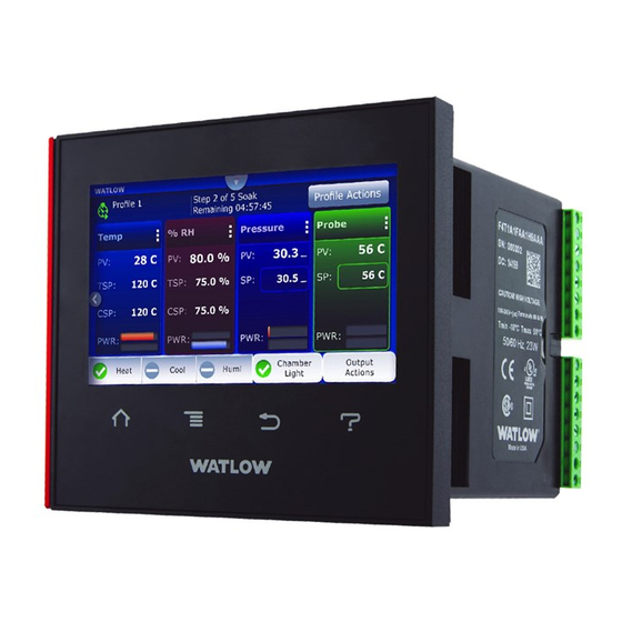
F4T Controller
Setup and Operations
User's Guide
1241 Bundy Boulevard., Winona, Minnesota USA 55987
Phone: +1 (507) 454-5300, Fax: +1 (507) 452-4507
http://www.watlow.com/F4T.cfm
TOTAL
CUSTOMER
SATISFACTION
3 Y ear Warranty
ISO 9001
Registered Company
Winona, Minnesota USA
Made in the U.S.A.
Advertisement
Chapters
Table of Contents

Related Manuals for Watlow F4T


Summary of Contents for Watlow F4T
- Page 1 F4T Controller Setup and Operations User’s Guide TOTAL CUSTOMER SATISFACTION 3 Y ear Warranty ISO 9001 Registered Company Winona, Minnesota USA 1241 Bundy Boulevard., Winona, Minnesota USA 55987 Phone: +1 (507) 454-5300, Fax: +1 (507) 452-4507 http://www.watlow.com/F4T.cfm 1680-2414 Rev. A Made in the U.S.A.
- Page 2 Safety Information We use note, caution and warning symbols throughout this document to draw your attention to important operational and safety information. A “NOTE” marks a short message to alert you to an important detail. A “CAUTION” safety alert appears with information that is important for protecting your equipment and performance.
- Page 3 Temperature Indicating-Regulating Equipment per CSA C22.2 No. 24. See: www.csa-international.org This F4T User’s Guide is copyrighted by Watlow Electric Manufacturing Company, © April 2016 with all rights reserved. • © 2010-2012, QNX Software Systems Limited. All rights reserved. • © 2008 -2014, Crank Software Inc. All rights reserved.
-
Page 4: Table Of Contents
Chapter 3: Using the F4T Front Panel . . . . . . . . . . . . . . . . . - Page 5 (cont .) Chapter 3: Using the F4T Front Panel (cont .) Data Logging . . . . . . . . . . . . . . . . . . . . . . . . . . . . . . . . . . . . . . . . . . . . . . . . . . . . . . . 54 Batch Processing Programming .
- Page 6 F4 Modbus Registers Migrated to F4T (Map 2) . . . . . . . . . . . . . . . .
-
Page 7: Chapter 1: Overview
0601-0001-0000 tion notes and more. To acquire one or more of these documents navigate to the Watlow website where you will have a choice to download free copies or purchase printed versions. Click on the link below to find your document of choice: http://www.watlow.com/literature/index.cfm... -
Page 8: Document Overview And Purpose
5. Watlow reserves the right to charge for no trouble found (NTF) returns. Document Overview and Purpose This document looks deeper at the system configuration using Composer™ software and the F4T function blocks and their associated connections. Common product usage is described and illustrated through application examples. Wat l ow F4T •... -
Page 9: A Conceptual View Of The F4T System
The F4T system can carry out several functions at the same time; such as, monitoring and acting upon various inputs (temperature sensing devices, pressure trans- ducers and digital inputs), PID control, monitoring for several different alarm situations and then driving output devices such as heaters, audible alarms, and lights. -
Page 10: Inputs
Composer software. To learn more about setting up function blocks see Chapter 2 of this document in the section titled "Configuring the Application with the Function Block Diagram View". Wat l ow F4T • 7 • C ha p t er 1 O v e r v i e w... -
Page 11: Outputs
Controllers equipped with this feature will have the letter [J, K, L or M] in the fifth character of its part number (see: F4T Ordering Information). Logging can be enabled at any time and is intended to capture real-time data for a user selectable list of data points. With firmware re- vision 3.0 and above, several new features are available. -
Page 12: Chapter 2: Composer ® Software
7. Clicking the Finish button will conclude the installation. Note: If experiencing difficulties installing or using Composer software, prior to contacting Watlow technical support, be prepared to send the user log file to the tech support team. This text file can be found here: C:\Users\username\AppData\Roaming\Watlow\Composer\ Logs The red text above will change to the user's Windows login name. -
Page 13: Using Composer ® Software
Connecting the PC to the Controller (System) - Physical Connections Physical connections (hardware and cabling) will vary depending on the controller in use. 1. To find instructions connecting an F4T controller to a PC see: Chapter 3 of the F4T Instal- lation and Troubleshooting User's Guide. - Page 14 • Displays all opened system images. Wat l ow F4T Co ntr oll er • 1 1 • Ch ap t er 2 Co n f igu ra t io n U s ing Co m po s e r...
-
Page 15: Overview Screen
Wa tlow F4T Co n tr ol ler • 1 2 • Ch a pt e r 2 Co n f ig u ra t io n U s ing C om po s e r... - Page 16 One or more of the profiles were created for a different con- Profile Editor figuration and cannot be run (F4T only). Pluggable At least one expected module is missing (F4T only). Modules ③ Security • When enabled, displays current level of access with the ability to logout.
- Page 17 • File Transfer: allows a user to transfer files (Configuration, Profile and Data log) to/ from the controller. Wa tlow F4T Co n tr ol ler • 1 4 • Ch a pt e r 2 Co n f ig u ra t io n U s ing C om po s e r...
- Page 18 • Function Block Diagram in its entirety • System Security • Profiles (F4T with profile option only) • Profile passwords (F4T with profile option only) • All parameters that can be read and written to Wat l ow F4T Co ntr oll er...
- Page 19 3. Use the save as dialog to select the destination folder for the image. 4. Enter the desired filename. 5. Click Save. Note: The system image filename will always have the extension wsi for Watlow System Image and cannot be changed. Note: The real-time clock values are not saved or imported.
-
Page 20: Device Details
Wat l ow F4T Co ntr oll er • 1 7 • Ch ap t er 2 Co n f igu ra t io n U s ing Co m po s e r... -
Page 21: Configuring Pluggable Flex Modules
• Click on the X to tell the system there will be no module installed in this slot. Taking Wa tlow F4T Co n tr ol ler • 1 8 • Ch a pt e r 2 Co n f ig u ra t io n U s ing C om po s e r... - Page 22 A restart will stop all controller activities while turning off all outputs. Wat l ow F4T Co ntr oll er • 1 9 • Ch ap t er 2 Co n f igu ra t io n U s ing Co m po s e r...
-
Page 23: Configuring The Application Using The Function Block Diagram
Errors: describes how to view signal values and errors as they oc- cur. Wa tlow F4T Co n tr ol ler • 2 0 • Ch a pt e r 2 Co n f ig u ra t io n U s ing C om po s e r... - Page 24 • Topic based video help files. Wat l ow F4T Co ntr oll er • 2 1 • Ch ap t er 2 Co n f igu ra t io n U s ing Co m po s e r...
- Page 25 Drag window here to dock at the right of the screen. Wa tlow F4T Co n tr ol ler • 2 2 • Ch a pt e r 2 Co n f ig u ra t io n U s ing C om po s e r...
- Page 26 Wat l ow F4T Co ntr oll er • 2 3 • Ch ap t er 2 Co n f igu ra t io n U s ing Co m po s e r...
- Page 27 2. Click Show/Hide Data Wa tlow F4T Co n tr ol ler • 2 4 • Ch a pt e r 2 Co n f ig u ra t io n U s ing C om po s e r...
- Page 28 • Click the FB and view the help window. Wat l ow F4T Co ntr oll er • 2 5 • Ch ap t er 2 Co n f igu ra t io n U s ing Co m po s e r...
- Page 29 Wa tlow F4T Co n tr ol ler • 2 6 • Ch a pt e r 2 Co n f ig u ra t io n U s ing C om po s e r...
-
Page 30: Personalizing The User Interface (Ui) Using Composer
Personalizing the User Interface (UI) Using Composer ® The home screen of the F4T controller can be personalized to show multiple pages and mul- tiple content blocks within each (4 maximum). Until personalized, the home screen will be blank. Features that are available on... - Page 31 When transferring files via TFTP, do not create a file on the server called "testfile". Communications between the F4T and the TFTP server is tested prior to starting a transfer using this filename while then verifying the response from the server.
- Page 32 Note: Due to wear-leveling operations of flash memory devices (internal - F4T and exter- nal - USB), there may be some gaps within the data logged file. Note: If logged file is sent to USB, the *.csv and the *.enc file are written directly to USB constantly.
- Page 33 Need Host IP IP address not present Settings > Network > Ethernet. • Ping the F4T to verify its presence on the network. Wa tlow F4T Co n tr ol ler • 3 0 • Ch a pt e r 2 Co n f ig u ra t io n U s ing C om po s e r...
- Page 34 Windows File Sharing. Within this document, SMB/CIFS will be referred to as Samba. Samba, when in use, creates a directory on the F4T device that maps to a shared directory on the user’s PC. There are several ways that a Windows shared drive can be configured. With this is mind, one of those ways will be discussed and used for demonstration purposes below.
- Page 35 15. Enter the object name "Samba" and then click on the Check Names button. Wa tlow F4T Co n tr ol ler • 3 2 • Ch a pt e r 2 Co n f ig u ra t io n U s ing C om po s e r...
- Page 36 The graphics that follow illustrate automatic transfer. Wat l ow F4T Co ntr oll er • 3 3 • Ch ap t er 2 Co n f igu ra t io n U s ing Co m po s e r...
- Page 37 In order to use the TFTP file transfer option, a TFTP server must be setup and running on your computer to service the TFTP transfers from the F4T. The user will need to specify the IP address of the remote computer, and also the remote computer name.
-
Page 38: Creating And Editing Profiles Using Composer
3. Start the TFTP server and then start data logging by pushing the following buttons on the F4T front panel: Main Menu > Data Logging > Start If the file does not seem to be transferring as expected check out the parameter identified... - Page 39 The following settings apply to the entire profile. Wa tlow F4T Co n tr ol ler • 3 6 • Ch a pt e r 2 Co n f ig u ra t io n U s ing C om po s e r...
- Page 40 Step timing will be impacted if the a profile is running and the time settings are changed. Wat l ow F4T Co ntr oll er • 3 7 • Ch ap t er 2 Co n f igu ra t io n U s ing Co m po s e r...
- Page 41 • Unchanged: the step does not set the event output; it remains in whatever state was previously set. Wa tlow F4T Co n tr ol ler • 3 8 • Ch a pt e r 2 Co n f ig u ra t io n U s ing C om po s e r...
- Page 42 2. Use the open dialog to locate and select the desired profile file. Wat l ow F4T Co ntr oll er • 3 9 • Ch ap t er 2 Co n f igu ra t io n U s ing Co m po s e r...
- Page 43 Wa tlow F4T Co n tr ol ler • 4 0 • Ch a pt e r 2 Co n f ig u ra t io n U s ing C om po s e r...
- Page 44 3. Click the Password button. 4. Click the Remove button. Wat l ow F4T Co ntr oll er • 4 1 • Ch ap t er 2 Co n f igu ra t io n U s ing Co m po s e r...
- Page 45 Log Files Using Composer. Wa tlow F4T Co n tr ol ler • 4 2 • Ch a pt e r 2 Co n f ig u ra t io n U s ing C om po s e r...
-
Page 46: Chapter 3: Using The F4T Front Panel
This chapter is designed to give the user a better understanding of the structure and naviga- tion of the F4T menus as viewed from the front panel. Understanding F4T Menus The graphic below illustrates at a high level the structure of the F4T menus. Home Main Menu... - Page 47 "Don't show this again" (shown in red box for emphasis only). Wa tlow F4T Co n tr ol ler • 4 4 • C ha pt er 3 U sin g t h e F 4 T Fro n t P a n e l...
-
Page 48: Home Screen Described
Screen). Front Panel Navigational Buttons When looking at the front panel of the F4T, at the bottom of the display, four push buttons are displayed as icons shown below. The text in this graphic was placed there for clarity only and is not present on the front panel. -
Page 49: Configuring Ethernet Communications
1. Push the Menu, Settings and Network buttons, in that order. 2. Push Ethernet. 3. Change desired settings. For Ethernet connectivity options and step-by-step instructions on connecting the F4T into an Ethernet network, see chapter 3 of the F4T Installation and Troubleshooting User's Guide. Default Ethernet Parameters and Settings The bracketed bold settings below represent the defaults as delivered from the factory: •... -
Page 50: Personalizing The Home Screen Using The Ui
- Data Map, the user can switch Modbus registers from the comprehensive listing of F4T reg- isters to a limited set of the legacy F4 controller registers (1 = F4T, 2 = F4 compatibility). Personalizing the Home Screen Using the UI Placement of objects on the home screen can be modified by the user. - Page 51 5. Push Page 1. 6. Select two content blocks. Wa tlow F4T Co n tr ol ler • 4 8 • C ha pt er 3 U sin g t h e F 4 T Fro n t P a n e l...
-
Page 52: Front Panel Usage From The Home Screen
- Cancel New Profile, removes the profile from the controller. - Close, closes the open window. Wat l ow F4T • 4 9 • C ha p t er 3 U sin g t h e F4 T Fro n t P a n e l... - Page 53 - Cancel, returns the display to the step editor. Wa tlow F4T Co n tr ol ler • 5 0 • C ha pt er 3 U sin g t h e F 4 T Fro n t P a n e l...
-
Page 54: Profile Actions From The Home Screen
> Create a new profile (see: Creating and Editing profiles). > Return to Home screen. Wat l ow F4T • 5 1 • C ha p t er 3 U sin g t h e F4 T Fro n t P a n e l... -
Page 55: Starting A Profile Using The Calendar
PID settings and many other parameters. Some of the available options accessible through this access point are shown below. Be aware Wa tlow F4T Co n tr ol ler • 5 2 • C ha pt er 3 U sin g t h e F 4 T Fro n t P a n e l... -
Page 56: Using The Output Widget
As an example, the F4T can have up to 5 PID sets. The screen shot below shows access to one PID set. Using the Output Widget In the graphic below, the output widget it is located at the bottom of the screen within the red box. -
Page 57: Data Logging
3. Push the desired position (1 to 4) and define its function. 4. Push the Done button when complete. Data Logging - To view video go to www.watlow.com/F4T. Data Logging can be enabled at any time and will log a user selectable list of data points. - Page 58 The filename format will be "Profile name" "date stamp" "time stamp".csv". Wat l ow F4T • 5 5 • C ha p t er 3 U sin g t h e F4 T Fro n t P a n e l...
-
Page 59: Batch Processing Programming
Click Done when finished Verify part to profile list is correct Wat l ow F4T • 5 6 • C ha p t er 3 U sin g t h e F4 T Fro n t P a n e l... - Page 60 Up to 25 different custom named fields can be added Set up of batch processing complete Wat l ow F4T • 5 7 • C ha p t er 3 U sin g t h e F4 T Fro n t P a n e l...
- Page 61 Batch Entry - Load completed both start automatically Wa tlow F4T Co n tr ol ler • 5 8 • C ha pt er 3 U sin g t h e F 4 T Fro n t P a n e l...
- Page 62 B) If operator scans “Unload Operator” bar code the controller will advance to screen 5 When user selects “Complete” confirming that all unload batch fields have been entered the F4T/D4T automatically returns back to home screen Batch report data log file...
-
Page 63: Export Data Log Report - Via Usb Stick
Use existing "File Transfer" method to export data log file now formatted as a Batch Report (configuration, profiles, data log) Scenario described below: Export via USB stick plugged into F4T/D4T controller. Microsoft Excel view of Batch Report (.CSV file format) -
Page 64: Adding "Part-Profile List" Using A Pc
Test 1 = Profile 1 desired part(s) Test 2 = Profile 2 1. Export the “Part-Profile List” file from the F4T onto a USB thumb drive 2. With USB stick plugged into PC, open ProfileToPart.json file on a PC using WordPad program (not Notepad) 3. - Page 65 Wa tlow F4T Co n tr ol ler • 6 2 • C ha pt er 3 U sin g t h e F 4 T Fro n t P a n e l...
- Page 66 Adding "Part-Profile List" using a PC (con't) 6. Save the WordPad file to a USB thumb drive 7. Import "Part-Profile List" file back into the F4T and verify list of parts listed to each profile Wat l ow F4T • 6 3 •...
-
Page 67: Transferring Data Log Files Via The Ui
1. Copy the file "F4TUpdate" to the root directory of a USB thumb drive. 2. Insert the USB thumb drive into either of the USB ports on the back of the F4T. Wa tlow F4T Co n tr ol ler •... - Page 68 After executing step 6 above, the three screen shots below will appear on screen as the flashing activity proceeds. Copy files: Step 1 of 3 : Moving file froom USB flash drive to F4T... Please do not disconnect USB flash drive or system power until update completes.
-
Page 69: Chapter 4: Application Examples
2 on module 2 to switch the heater that heats the chamber or oven accordingly. Function Block Diagram Wat l ow F4T • 6 6 • Ch a pt e r 4 Ap plica t ion E x a m pl e s... -
Page 70: Heat And Cool Control Loop
2 on module 2 to heat the chamber and output 2 on module 1 to cool the chamber as needed. Wa tlow F4T • 6 7 • Ch a pt e r 4 A p plica t io n E x a m pl e s... - Page 71 Don’t use this setting with mechanical relays or switching devices or loads that are not purely resistive. Wat l ow F4T • 6 8 • Ch a pt e r 4 Ap plica t ion E x a m pl e s...
-
Page 72: Process Alarm
• Enter names for blocks where possible to make the application easier to understand. Wa tlow F4T • 6 9 • Ch a pt e r 4 A p plica t io n E x a m pl e s... -
Page 73: Deviation Alarm
Function Block Diagram Wat l ow F4T • 7 0 • Ch a pt e r 4 Ap plica t ion E x a m pl e s... - Page 74 • For more information on alarm parameters see the section entitled "Alarm" in Chapter Wa tlow F4T • 7 1 • Ch a pt e r 4 A p plica t io n E x a m pl e s...
-
Page 75: Safety Limit
• The signal from the digital input to the RST on the limit block allows a momentary switch wired to that input to reset the limit alarm. Wat l ow F4T • 7 2 • Ch a pt e r 4 Ap plica t ion E x a m pl e s... -
Page 76: Sensor Backup
Function Block Diagram Wa tlow F4T • 7 3 • Ch a pt e r 4 A p plica t io n E x a m pl e s... -
Page 77: Profile Ramp And Soak
Function Block Diagram Wat l ow F4T • 7 4 • Ch a pt e r 4 Ap plica t ion E x a m pl e s... -
Page 78: Cascade Control
Wa tlow F4T • 7 5 • Ch a pt e r 4 A p plica t io n E x a m pl e s... - Page 79 • For more information on cascade control parameters see the section entitled "Cascade" in Chapter 5. Wat l ow F4T • 7 6 • Ch a pt e r 4 Ap plica t ion E x a m pl e s...
-
Page 80: Compressor Control
Special Output function block configured for com- pressor control. Function Block Diagram Wa tlow F4T • 7 7 • Ch a pt e r 4 A p plica t io n E x a m pl e s... - Page 81 • For more information on compressor control parameters see the section entitled "Com- pressor Control" in Chapter 5. Wat l ow F4T • 7 8 • Ch a pt e r 4 Ap plica t ion E x a m pl e s...
-
Page 82: Chapter 5: Function Block Reference
Limit Output . . . . . . . . . . . . . . . . . . . . . . . . . . . . . . . . . . . . . . . . . . . . . . . . . . . . . 140 Wa tlow F4T •... - Page 83 Crossover . . . . . . . . . . . . . . . . . . . . . . . . . . . . . . . . . . . . . . . . . . . . . . . . . . . . . . . . . . . . . . 177 Wat l ow F4T •...
- Page 84 Digital . . . . . . . . . . . . . . . . . . . . . . . . . . . . . . . . . . . . . . . . . . . . . . . . . . . . . . . . . . . . . . . . . 218 Wa tlow F4T •...
-
Page 85: F4T Functions Described
F4T Functions Described The controller is customized by connecting function blocks (FB) as needed for the application. A transmitter of one function is commonly connected to a receiver of another using Com- poser's function block diagram editor. The connections between blocks, referred to as signals, carry information from one function block to another. -
Page 86: Alarm
Alarm: monitors an analog signal for specified alarm conditions. Deviation Alarm: monitors an analog signal for alarm conditions relative to another signal. Wat l ow F4T • 8 3 • Ch ap t er 5 Fu n ct io n Re f e r e n c e... -
Page 87: Off
Range: 1 to 9,999 °F or units 2 to 5,555 °C Wa tlow F4T • 8 4 • Ch ap t er 5 Fu n ct io n R e f e r e n c e... - Page 88 • Off: when an alarm is active there will be no indication on the UI. Wat l ow F4T • 8 5 • Ch ap t er 5 Fu n ct io n Re f e r e n c e...
-
Page 89: Deviation Alarm
The alarm’s behavior can be further customized with Logic, Latching, Blocking, Silencing and Delay Time parameters. Wa tlow F4T • 8 6 • Ch ap t er 5 Fu n ct io n R e f e r e n c e... - Page 90 Range: 1 to 9,999 °F or units 2 to 5,555 °C Wat l ow F4T • 8 7 • Ch ap t er 5 Fu n ct io n Re f e r e n c e...
- Page 91 • Off: when an alarm is active there will be no indication on the UI. Wa tlow F4T • 8 8 • Ch ap t er 5 Fu n ct io n R e f e r e n c e...
- Page 92 Input has an error The Alarm State indicates there is an error and the output is active. Wat l ow F4T • 8 9 • Ch ap t er 5 Fu n ct io n Re f e r e n c e...
-
Page 93: Analog Outputs
0%, and the Range High is set to 100%, the output can be limited by setting the Scale Low and Scale High parameters to the desired minimum and maximum signal levels. Wa tlow F4T • 9 0 • Ch ap t er 5 Fu n ct io n R e f e r e n c e... - Page 94 When using the output for control, this is typically 100%. Range: -99,999.000 to 99,999.000 Wat l ow F4T • 9 1 • Ch ap t er 5 Fu n ct io n Re f e r e n c e...
-
Page 95: Cascade
The resultant inner loop set point is displayed (dashed lines) before any filtering or offset is applied. Wa tlow F4T • 9 2 • Ch ap t er 5 Fu n ct io n R e f e r e n c e... -
Page 96: Deviation
(PVO) and remote set point are virtually removed and the inner loop will now serve as a single loop PID controller. Wat l ow F4T • 9 3 • Ch ap t er 5 Fu n ct io n Re f e r e n c e... - Page 97 Off = On, Auto = Off, Manual = Off *Off Digital *Available in firmware release 3.0 and above. Wa tlow F4T • 9 4 • Ch ap t er 5 Fu n ct io n R e f e r e n c e...
- Page 98 • High: the block performs simple set point control when the signal is on • Low: the block performs simple set point control when the signal is off Wat l ow F4T • 9 5 • Ch ap t er 5 Fu n ct io n Re f e r e n c e...
- Page 99 Wa tlow F4T • 9 6 • Ch ap t er 5 Fu n ct io n R e f e r e n c e...
- Page 100 Range: -1,000.0 to 1,000.0 ºF or units -555 to 555 ºC Wat l ow F4T • 9 7 • Ch ap t er 5 Fu n ct io n Re f e r e n c e...
- Page 101 Range: -1,000.0 to 1,000.0 ºF or units -555 to 555 ºC Wa tlow F4T • 9 8 • Ch ap t er 5 Fu n ct io n R e f e r e n c e...
- Page 102 • Fixed Power: Manual Power is set equal to the Fixed Power setting • User: uses the current Manual Power setting Wat l ow F4T • 9 9 • Ch ap t er 5 Fu n ct io n Re f e r e n c e...
- Page 103 • High: the Control Mode is set to Manual when the signal is on • Low: the Control Mode is set to Manual when the signal is off Wa tlow F4T • 1 0 0 • Ch ap t er 5 Fu n ct io n R e f e r e n c e...
- Page 104 Set the value that will trigger a change (crossover point) from PID set 4 to set 5, relative to the selected source. Range: -99,000 to 99,999 Wat l ow F4T • 1 0 1 • Ch ap t er 5 Fu n ct io n Re f e r e n c e...
- Page 105 Range: 1 to 99,999 ºF or units 1 to 55,555 ºC Wa tlow F4T • 1 0 2 • Ch ap t er 5 Fu n ct io n R e f e r e n c e...
- Page 106 Set the high end of the range for the Manual Power. Range: -100.0 to 100.0% Wat l ow F4T • 1 0 3 • Ch ap t er 5 Fu n ct io n Re f e r e n c e...
- Page 107 Either the Remote Set Point parameter or the REN input can cause the remote set point to override the loop’s set point. Wa tlow F4T • 1 0 4 • Ch ap t er 5 Fu n ct io n R e f e r e n c e...
- Page 108 • Over: bring the process value to the set point with minimal overshoot • Under: bring the process value to the set point quickly tolerating overshoot Wat l ow F4T • 1 0 5 • Ch ap t er 5 Fu n ct io n Re f e r e n c e...
- Page 109 Choose the method the cascade loop uses to set power outputs HT, CL and PWR. Options: • Off: power outputs are 0% Wa tlow F4T • 1 0 6 • Ch ap t er 5 Fu n ct io n R e f e r e n c e...
-
Page 110: Compare
Equal To: the block’s output is on when the two inputs are equal Wat l ow F4T • 1 0 7 • Ch ap t er 5 Fu n ct io n Re f e r e n c e... -
Page 111: Off
To test if A is less than B, set Function to Less Than. Error Handling Wa tlow F4T • 1 0 8 • Ch ap t er 5 Fu n ct io n R e f e r e n c e... -
Page 112: Equal To
• False Good: outputs value is false (off) with no error • False Bad: outputs value is false (off) and has an error Wat l ow F4T • 1 0 9 • Ch ap t er 5 Fu n ct io n Re f e r e n c e... -
Page 113: Not Equal To
Function To test if A is greater than or equal to B, set Function to Greater or Equal. Wa tlow F4T • 1 1 0 • Ch ap t er 5 Fu n ct io n R e f e r e n c e... -
Page 114: Less Or Equal
• False Good: outputs value is false (off) with no error • False Bad: outputs value is false (off) and has an error Wat l ow F4T • 1 1 1 • Ch ap t er 5 Fu n ct io n Re f e r e n c e... -
Page 115: Control Loop
Active state disables TRU-TUNE+ overriding the Digital TRU-TUNE+ Enable setting. See: Disable TRU-TUNE+ Active Level Wa tlow F4T • 1 1 2 • Ch ap t er 5 Fu n ct io n R e f e r e n c e... - Page 116 Options: • On/Off: On-Off control sets the HT and PWR to (100%) on, or off (0%) Wat l ow F4T • 1 1 3 • Ch ap t er 5 Fu n ct io n Re f e r e n c e...
- Page 117 • PID: PID control sets the CL and PWR outputs to a value from no cooling 0% to full cool- ing (100% for CL and -100% for PWR) Wa tlow F4T • 1 1 4 • Ch ap t er 5 Fu n ct io n R e f e r e n c e...
- Page 118 Set how far above set point the process value must rise before the cool output turns on. This parameter applies only when Cool Algorithm is set to On-Off. Wat l ow F4T • 1 1 5 • Ch ap t er 5 Fu n ct io n Re f e r e n c e...
- Page 119 • Off: control mode set to off • Hold: maintain the last set point within the profile Wa tlow F4T • 1 1 6 • Ch ap t er 5 Fu n ct io n R e f e r e n c e...
- Page 120 Range: 0 to 9,999 seconds Wat l ow F4T • 1 1 7 • Ch ap t er 5 Fu n ct io n Re f e r e n c e...
- Page 121 Set the value that will trigger a change (crossover point) from PID set 1 to set 2, relative to the selected source. Range: -99,000 to 99,999 Wa tlow F4T • 1 1 8 • Ch ap t er 5 Fu n ct io n R e f e r e n c e...
- Page 122 This parameter is set automatically by autotuning the loop and when TRU-TUNE+ is enabled. Range: 0 to 99,999 seconds per repeat Wat l ow F4T • 1 1 9 • Ch ap t er 5 Fu n ct io n Re f e r e n c e...
- Page 123 • Both: the loop ramps the set point each time the controller is powered up or the Set Point is changed Wa tlow F4T • 1 2 0 • Ch ap t er 5 Fu n ct io n R e f e r e n c e...
- Page 124 • Auto: the remote set point is in the units of the PV input and overrides the Set Point when enabled Wat l ow F4T • 1 2 1 • Ch ap t er 5 Fu n ct io n Re f e r e n c e...
- Page 125 For example, if the active set Wa tlow F4T • 1 2 2 • Ch ap t er 5 Fu n ct io n R e f e r e n c e...
- Page 126 Options: • No: TRU-TUNE+ is off • Yes: TRU-TUNE+ is on Wat l ow F4T • 1 2 3 • Ch ap t er 5 Fu n ct io n Re f e r e n c e...
- Page 127 • Manual: open-loop control, the loop’s power outputs are set according to the Manual Power setting Wa tlow F4T • 1 2 4 • Ch ap t er 5 Fu n ct io n R e f e r e n c e...
-
Page 128: Counter
Digital On when the count equals the target value Function To increment the count with CNT, set Function to Up. Wat l ow F4T • 1 2 5 • Ch ap t er 5 Fu n ct io n Re f e r e n c e... -
Page 129: Down
CNT. OUT turns on when the count equals the target value. OUT turns off and the count is set equal to the load value by RST (reset). Wa tlow F4T • 1 2 6 • Ch ap t er 5 Fu n ct io n R e f e r e n c e... - Page 130 • Low: on to off Count Indicates the current count. Range: 0 to 9,999 Wat l ow F4T • 1 2 7 • Ch ap t er 5 Fu n ct io n Re f e r e n c e...
-
Page 131: Current Input
A Heater Error is used to determine if the load current flow is within the specified limits as set by the user through the High Set Point and Low Set Point. Wa tlow F4T • 1 2 8 • Ch ap t er 5 Fu n ct io n R e f e r e n c e... - Page 132 Set a value to be added to the measured input value to calibrate the current reading. Range: -99,999 to 99,999 Wat l ow F4T • 1 2 9 • Ch ap t er 5 Fu n ct io n Re f e r e n c e...
-
Page 133: Digital Input
Voltage: the block’s output is on when a sufficient voltage is detected by the corre- sponding input on the flex module. Wa tlow F4T • 1 3 0 • Ch ap t er 5 Fu n ct io n R e f e r e n c e... -
Page 134: Digital Inputs/Outputs (I/O)
Voltage: the block’s output is on when a sufficient voltage is detected by the corre- sponding input on the flex module. Wat l ow F4T • 1 3 1 • Ch ap t er 5 Fu n ct io n Re f e r e n c e... -
Page 135: Input Dry Contact
Options: • Fixed Time Base: the percent output power is converted to a duty cycle over the Fixed Wa tlow F4T • 1 3 2 • Ch ap t er 5 Fu n ct io n R e f e r e n c e... - Page 136 100% are scaled proportionally. See the illustration to the right. Range: 0.0 to 100.0% Wat l ow F4T • 1 3 3 • Ch ap t er 5 Fu n ct io n Re f e r e n c e...
-
Page 137: Digital Outputs
Wa tlow F4T • 1 3 4 • Ch ap t er 5 Fu n ct io n R e f e r e n c e... - Page 138 0% and 100% are scaled proportionally. See the il- lustration to the right. Range: 0.0 to 100.0% Wat l ow F4T • 1 3 5 • Ch ap t er 5 Fu n ct io n Re f e r e n c e...
-
Page 139: Electromechanical And No-Arc Relays
High Power Scale. Values between 0% and 100% are scaled proportionally. See the il- lustration below. Range: 0.0 to 100.0% Wa tlow F4T • 1 3 6 • Ch ap t er 5 Fu n ct io n R e f e r e n c e... -
Page 140: Key
Name Uniquely identify this FB using up to 20 alphanumeric characters. Wat l ow F4T • 1 3 7 • Ch ap t er 5 Fu n ct io n Re f e r e n c e... -
Page 141: Limit
Name Uniquely identify this FB using up to 20 alphanumeric characters. Wa tlow F4T • 1 3 8 • Ch ap t er 5 Fu n ct io n R e f e r e n c e... - Page 142 Set the process value that triggers the low limit. Range: Minimum Set Point to Maximum Set Point Wat l ow F4T • 1 3 9 • Ch ap t er 5 Fu n ct io n Re f e r e n c e...
-
Page 143: Limit Output
When the Linearize block’s function is set to Off, the output is off. Wa tlow F4T • 1 4 0 • Ch ap t er 5 Fu n ct io n R e f e r e n c e... -
Page 144: Interpolated
• Relative Humidity: the output is a measurement of percent relative humidity (%RH). Wat l ow F4T • 1 4 1 • Ch ap t er 5 Fu n ct io n Re f e r e n c e... - Page 145 Set the sixth lowest input value on the scaling curve. This value is scaled to Output Point 6. Range: -99,999.000 to 99,999.000 Wa tlow F4T • 1 4 2 • Ch ap t er 5 Fu n ct io n R e f e r e n c e...
-
Page 146: Stepped
The output is constant as the input is increased until the in- put reaches the next point where the output changes abruptly to the next value. Wat l ow F4T • 1 4 3 •... - Page 147 Input Point 3 are scaled to Output Point 2. Range: -99,999.000 to 99,999.000 Wa tlow F4T • 1 4 4 • Ch ap t er 5 Fu n ct io n R e f e r e n c e...
- Page 148 Set the value to which the input is scaled when the input is greater than or equal to Input Point 6 and less than Input Point 7. Range: -99,999.000 to 99,999.000 Wat l ow F4T • 1 4 5 • Ch ap t er 5 Fu n ct io n Re f e r e n c e...
- Page 149 Set an adjustment to the final value, added after scaling. Range: -99,999.000 to 99,999.000 Wa tlow F4T • 1 4 6 • Ch ap t er 5 Fu n ct io n R e f e r e n c e...
-
Page 150: Logic
F = False (0%, off) T = True (100%, on) Wat l ow F4T • 1 4 7 • Ch ap t er 5 Fu n ct io n Re f e r e n c e... -
Page 151: Nand
F = False (0%, off) T = True (100%, on) Wa tlow F4T • 1 4 8 • Ch ap t er 5 Fu n ct io n R e f e r e n c e... -
Page 152: Equal To
F = False (0%, off) T = True (100%, on) Wat l ow F4T • 1 4 9 • Ch ap t er 5 Fu n ct io n Re f e r e n c e... -
Page 153: Not Equal To
F = False (0%, off) T = True (100%, on) Wa tlow F4T • 1 5 0 • Ch ap t er 5 Fu n ct io n R e f e r e n c e... - Page 154 F = False (0%, off) T = True (100%, on) Wat l ow F4T • 1 5 1 • Ch ap t er 5 Fu n ct io n Re f e r e n c e...
-
Page 155: Nor
F = False (0%, off) T = True (100%, on) Wa tlow F4T • 1 5 2 • Ch ap t er 5 Fu n ct io n R e f e r e n c e... -
Page 156: Latch
3. If Hold becomes true after IN becomes true, the output remains true as long as Hold is true even after IN becomes false. Wat l ow F4T • 1 5 3 • Ch ap t er 5 Fu n ct io n Re f e r e n c e... -
Page 157: Rs Flip Flop
True after being set by the Set input and false after being Transmitter - - - - Digital reset by Rst Wa tlow F4T • 1 5 4 • Ch ap t er 5 Fu n ct io n R e f e r e n c e... -
Page 158: Math
Library when working with a controller that offers the Math block. Within the Library, the number of these blocks available is shown in parenthesis. Wat l ow F4T • 1 5 5 • Ch ap t er 5 Fu n ct io n Re f e r e n c e... -
Page 159: Off
Excessive filtering slows the function’s response. Range: 0.0 to 60.0 seconds Wa tlow F4T • 1 5 6 • Ch ap t er 5 Fu n ct io n R e f e r e n c e... -
Page 160: Signals
To select one of two analog inputs with a digital input, set Function to Switch Over. Offset Adjustment added to the selected value. Range: -99,999.000 to 99,999 Wat l ow F4T • 1 5 7 • Ch ap t er 5 Fu n ct io n Re f e r e n c e... -
Page 161: Process Scale
Low and Range Low are the coordinates of a point on the line that relates input X to the scaled output. Range: -99,999.000 to 99,999.000 Wa tlow F4T • 1 5 8 • Ch ap t er 5 Fu n ct io n R e f e r e n c e... - Page 162 Offset Adjustment added to the result of the calculation. Range: -99,999.000 to 99,999.000 Wat l ow F4T • 1 5 9 • Ch ap t er 5 Fu n ct io n Re f e r e n c e...
-
Page 163: Deviation Scale
To adjust an input by an amount proportional to another input, set Function to Deviation Scale. Wa tlow F4T • 1 6 0 • Ch ap t er 5 Fu n ct io n R e f e r e n c e... -
Page 164: Differential
The filtered result of the calculation (X – Y) plus the offset Function To subtract one input from another, set Function to Differential. Wat l ow F4T • 1 6 1 • Ch ap t er 5 Fu n ct io n Re f e r e n c e... -
Page 165: Ratio
Transmitter - - - - Analog The filtered sum of the inputs plus the offset Wa tlow F4T • 1 6 2 • Ch ap t er 5 Fu n ct io n R e f e r e n c e... -
Page 166: Multiply
This function calculates the absolute value of input X minus input Y. A filter and offset may be applied to the calculated value. The output has the units of input x. Wat l ow F4T • 1 6 3 •... -
Page 167: Minimum
Excessive filtering slows the function’s response. Range: 0.0 to 60.0 seconds Wa tlow F4T • 1 6 4 • Ch ap t er 5 Fu n ct io n R e f e r e n c e... -
Page 168: Maximum
Excessive filtering slows the function’s response. Range: 0.0 to 60.0 seconds Wat l ow F4T • 1 6 5 • Ch ap t er 5 Fu n ct io n Re f e r e n c e... -
Page 169: Sample And Hold
To calculate the standard distance above sea level based on an atmospheric pressure, set Function to Pressure to Altitude. Wa tlow F4T • 1 6 6 • Ch ap t er 5 Fu n ct io n R e f e r e n c e... -
Page 170: Dew Point
Excessive filtering slows the function’s response. Range: 0.0 to 60.0 seconds Wat l ow F4T • 1 6 7 • Ch ap t er 5 Fu n ct io n Re f e r e n c e... - Page 171 The output’s value and error follow the first All inputs have errors input. Wa tlow F4T • 1 6 8 • Ch ap t er 5 Fu n ct io n R e f e r e n c e...
-
Page 172: Profile
Appendix, see the section entitled "Using Modbus to Determine Profile Selection". Wat l ow F4T • 1 6 9 • Ch ap t er 5 Fu n ct io n Re f e r e n c e... - Page 173 Active Level When on, disables the profile engine. See Enable/Disable Digital Profile Wa tlow F4T • 1 7 0 • Ch ap t er 5 Fu n ct io n R e f e r e n c e...
- Page 174 Minutes, Hours and Day of Week parameters. Range: 0 to 59 Wat l ow F4T • 1 7 1 • Ch ap t er 5 Fu n ct io n Re f e r e n c e...
- Page 175 • High: the profile pauses when the signal is on and continues when the signal is off • Low: the profile pauses when the signal is off and continues when the signal is on Wa tlow F4T • 1 7 2 •...
- Page 176 Set the name to display for event 3 in the controller user interface and in the profile editor. Options: • Any alphanumeric character (20 maximum) Wat l ow F4T • 1 7 3 • Ch ap t er 5 Fu n ct io n Re f e r e n c e...
- Page 177 Options: • Off: the event is off • On: the event is on Wa tlow F4T • 1 7 4 • Ch ap t er 5 Fu n ct io n R e f e r e n c e...
-
Page 178: Process Value
Altitude: calculates the standard distance above sea level based on an atmospher- ic pressure. Wat l ow F4T • 1 7 5 • Ch ap t er 5 Fu n ct io n Re f e r e n c e... -
Page 179: Off
Function to Sensor Backup. Offset Adjustment added to the output. Range: -99,999.000 to 99,999.000 Wa tlow F4T • 1 7 6 • Ch ap t er 5 Fu n ct io n R e f e r e n c e... -
Page 180: Average
A and B. At the high end of the range only B is considered. Wat l ow F4T • 1 7 7 •... -
Page 181: Wet Bulb / Dry Bulb
Transmitter - - - - Analog The filtered relative humidity plus the offset Wa tlow F4T • 1 7 8 • Ch ap t er 5 Fu n ct io n R e f e r e n c e... -
Page 182: Switch Over
Excessive filtering slows the function’s response. Range: 0.0 to 60.0 seconds Wat l ow F4T • 1 7 9 • Ch ap t er 5 Fu n ct io n Re f e r e n c e... -
Page 183: Differential
Excessive filtering slows the function’s response. Range: 0.0 to 60.0 seconds Wa tlow F4T • 1 8 0 • Ch ap t er 5 Fu n ct io n R e f e r e n c e... -
Page 184: Add
Function To compute the product of up to four inputs, set Function to Multiply. Wat l ow F4T • 1 8 1 • Ch ap t er 5 Fu n ct io n Re f e r e n c e... -
Page 185: Absolute Difference
Transmitter - - - - Analog The filtered lowest value of the inputs plus the offset Wa tlow F4T • 1 8 2 • Ch ap t er 5 Fu n ct io n R e f e r e n c e... -
Page 186: Maximum
Transmitter - - - - Analog The filtered square root of input X plus the offset Wat l ow F4T • 1 8 3 • Ch ap t er 5 Fu n ct io n Re f e r e n c e... -
Page 187: Vaisala ® Rh Compensation
The standard is based on an altitude of 0 feet (sea level) pressure of 14.6967 PSI and a temperature of 59 °F. Wa tlow F4T • 1 8 4 • Ch ap t er 5 Fu n ct io n R e f e r e n c e... - Page 188 Wet Bulb Dry DRY or WET or both have errors RH has an error Bulb Wat l ow F4T • 1 8 5 • Ch ap t er 5 Fu n ct io n Re f e r e n c e...
- Page 189 The output’s value is calculated as usu- X has an error Altitude al and has an error. Wa tlow F4T • 1 8 6 • Ch ap t er 5 Fu n ct io n R e f e r e n c e...
-
Page 190: Special Output
Turn On setting (-2%) and the Mini- mum Off Time (15 sec) has been Wat l ow F4T • 1 8 7 • Ch ap t er 5 Fu n ct io n Re f e r e n c e... - Page 191 ⑤ Once Input B rises above 5% the Off Delay timer is activated. When that time has been satisfied the compressor goes off. Wa tlow F4T • 1 8 8 • Ch ap t er 5 Fu n ct io n R e f e r e n c e...
- Page 192 Set the minimum amount of time the compressor is kept off before it can be turned on again. Range: 0 to 9,999 seconds Wat l ow F4T • 1 8 9 • Ch ap t er 5 Fu n ct io n Re f e r e n c e...
-
Page 193: Sequencer
To operate a proportional power control and up to three on-off power controls as if they were a single, larger, proportional controller, set Function to Sequencer. Wa tlow F4T • 1 9 0 • Ch ap t er 5 Fu n ct io n R e f e r e n c e... -
Page 194: Motorized Valve
Set this to the time the valve takes to travel between fully closed and fully open. Range: 10 to 9,999 seconds Wat l ow F4T • 1 9 1 • Ch ap t er 5 Fu n ct io n Re f e r e n c e... -
Page 195: Temperature Input
Range: -99,999.000 to 99,999.000°F or units -55,555.000 to 55,555.000°C Wa tlow F4T • 1 9 2 • Ch ap t er 5 Fu n ct io n R e f e r e n c e... -
Page 196: Thermocouple
Set how many decimal places are displayed for the process value and associated parameters such as set points. Options: Whole, Tenths, Hundredths, Thousandths Wat l ow F4T • 1 9 3 • Ch ap t er 5 Fu n ct io n Re f e r e n c e... - Page 197 Set this parameter to Clear to reset the input error after correcting the condition that caused Options: Ignore, Clear Wa tlow F4T • 1 9 4 • Ch ap t er 5 Fu n ct io n R e f e r e n c e...
-
Page 198: Thermistor Input
Use Steinhart-Hart equation coefficients (A, B and C) from thermis- tor manufacturer corresponding to the terms of the Steinhart-Hart Custom equation: Wat l ow F4T • 1 9 5 • Ch ap t er 5 Fu n ct io n Re f e r e n c e... - Page 199 Range: -99,999.000 to 99,999.000°F or units -55,555.000 to 55,555.000°C Wa tlow F4T • 1 9 6 • Ch ap t er 5 Fu n ct io n R e f e r e n c e...
-
Page 200: Timer
Shot: triggers the output by setting the time, timer counts down while the input is ac- tive, output is active until time runs out. Wat l ow F4T • 1 9 7 • Ch ap t er 5 Fu n ct io n Re f e r e n c e... -
Page 201: Off
(off) to high (on). However, if the input’s active state is set to Low, the timer starts running (becomes active) when the input changes from high (on) to low (off). Wa tlow F4T • 1 9 8 •... - Page 202 Note: The elapsed time is not retained through a power loss; it is set to zero upon power up. Wat l ow F4T • 1 9 9 • Ch ap t er 5 Fu n ct io n Re f e r e n c e...
-
Page 203: Delay
Set which state change at RUN starts the timer. This is the state change that is delayed. Options: • High: off to on • Low: on to off Wa tlow F4T • 2 0 0 • Ch ap t er 5 Fu n ct io n R e f e r e n c e... -
Page 204: One Shot
(off) to high (on). However, if the input’s active state is set to Low, the timer starts running (becomes active) when the input changes from high (on) to low (off). Wat l ow F4T • 2 0 1 •... - Page 205 The elapsed time resets to zero once the Time parameter has counted down to zero. Range: 0 to 99,999.000 Wa tlow F4T • 2 0 2 • Ch ap t er 5 Fu n ct io n R e f e r e n c e...
-
Page 206: Retentive
Set the cumulative amount of time the input must be active before the output becomes ac- tive. Range: 0 to 30,000.0 Wat l ow F4T • 2 0 3 • Ch ap t er 5 Fu n ct io n Re f e r e n c e... -
Page 207: Universal Input
Ohm: use this sensor type to condition a temperature measurement made with an RTD. Wa tlow F4T • 2 0 4 • Ch ap t er 5 Fu n ct io n R e f e r e n c e... -
Page 208: Millivolts/Volts
Universal Inputs installed and configured for voltage (millivolts or voltage). Wat l ow F4T • 2 0 5 • Ch ap t er 5 Fu n ct io n Re f e r e n c e... - Page 209 Use to set maximum value of the process range in electrical units. Range: -100.0 to 1000.0 VDC -100.0 to 1000.0 mVDC Wa tlow F4T • 2 0 6 • Ch ap t er 5 Fu n ct io n R e f e r e n c e...
- Page 210 Excessive filtering slows the input’s response. Range: 0.0 to 60.0 seconds Wat l ow F4T • 2 0 7 • Ch ap t er 5 Fu n ct io n Re f e r e n c e...
-
Page 211: Off
Sensor Type To detect and condition a temperature measurement set Sensor Type to Thermocouple. Wa tlow F4T • 2 0 8 • Ch ap t er 5 Fu n ct io n R e f e r e n c e... -
Page 212: Milliamps
Universal Input. The Universal Input number indicates the specific input on the flex module. Wat l ow F4T • 2 0 9 • Ch ap t er 5 Fu n ct io n Re f e r e n c e... - Page 213 Use to set maximum value of the process range in electrical units. Range: -100.0 to 1000.0 VDC -100.0 to 1000.0 mVDC Wa tlow F4T • 2 1 0 • Ch ap t er 5 Fu n ct io n R e f e r e n c e...
- Page 214 Excessive filtering slows the input’s response. Range: 0.0 to 60.0 seconds Wat l ow F4T • 2 1 1 • Ch ap t er 5 Fu n ct io n Re f e r e n c e...
-
Page 215: Resistance Temperature Device (Rtd) 100 And 1000 Ohm
Set how many decimal places are displayed for the process value and associated parameters such as set points. Options: Whole, Tenths, Hundredths, Thousandths Wa tlow F4T • 2 1 2 • Ch ap t er 5 Fu n ct io n R e f e r e n c e... -
Page 216: 1K Potentiometer
To detect and condition a resistance signal for use with other FBs, set Sensor Type to Potenti- ometer. Wat l ow F4T • 2 1 3 • Ch ap t er 5 Fu n ct io n Re f e r e n c e... - Page 217 Use to set the maximum value in process units. Range: -99,999.000 to 99,999.000°F or units -55,555 to 55,555°C Wa tlow F4T • 2 1 4 • Ch ap t er 5 Fu n ct io n R e f e r e n c e...
- Page 218 Set this parameter to Clear to reset the input error after correcting the condition that caused Options: Ignore, Clear Wat l ow F4T • 2 1 5 • Ch ap t er 5 Fu n ct io n Re f e r e n c e...
-
Page 219: Variable
Variable function appears as shown at the left. See Units below for more informa- tion on when to use relative temperature vs. absolute temperature. Wa tlow F4T • 2 1 6 • Ch ap t er 5 Fu n ct io n R e f e r e n c e... - Page 220 Analog Set the value of the function’s output. Range: -99,999.000 to 99,999.000 Wat l ow F4T • 2 1 7 • Ch ap t er 5 Fu n ct io n Re f e r e n c e...
-
Page 221: Digital
Set the state of the function’s output. Options: • On: On or True • Off: Off or False Wa tlow F4T • 2 1 8 • Ch ap t er 5 Fu n ct io n R e f e r e n c e... -
Page 222: Chapter 6: Appendix
SCPI commands, all of which are not included in this implementation. Although the SCPI protocol can be deployed over multiple physical layers Watlow has imple- mented this protocol over Ethernet port 502. The available SCPI commands are shown below: 1. - Page 223 30. :OUTPut#:STATe ON - Set the event output on where # is the output number (1-8) - Example :OUTPUT3:STATE ON – set event output 3 on Wat l ow F4T • 2 2 0 • C h ap t er 6 A p p e n d i x...
-
Page 224: Introduction To The Modbus Protocol
All Modbus registers are 16-bits and are listed in the following table as relative addresses (ac- tual). Some F4T parameters are contained within 32 bits (IEEE float, signed 32 bit), notice that only one (low order) of the two registers is listed. By default, the low order word contains the two low bytes of the 32-bit parameter. - Page 225 Modbus registers (Profile List Member) displayed with index values to the right. With the profile listing as shown below, Modbus register 48000 (Profile List Count) would be equal to 6. Wat l ow F4T • 2 2 2 •...
-
Page 226: Modbus Table Orientation
Modbus Relative Address - Identifies unique parameters addresses using either the Modbus RTU or Modbus TCP protocols (further explanation below). Watl ow F4T • 2 2 3 • C h ap t er 6 A p p e n d i x... - Page 227 3. Note offset (red arrow) to the next Modbus address from the base, in this case 110. 4. Multiply the displayed offset by two and add that to the base number (110 x 2) + 29346). F4T Modbus Registers (Map 1) Parameter Class...
- Page 228 "unsigned 16-bit Logic Close On Alarm (17) Alarm n: 1346+((n-1)* Open On Alarm (66)" Access = RW" 100)" Wat l ow F4T • 2 2 5 • C h ap t er 6 A p p e n d i x...
- Page 229 "High (37) "unsigned 16-bit Off Active Level High (37) Alarm n: 1408+((n-1)* Low (53)" Access = RW" 100)" Wat l ow F4T • 2 2 6 • C h ap t er 6 A p p e n d i x...
- Page 230 "No (59) "unsigned 16-bit Autotune No (59) Control Loop n: Yes (106)" Access = RW" 2754+((n-1)* 160)" Wat l ow F4T • 2 2 7 • C h ap t er 6 A p p e n d i x...
- Page 231 Input Error Power User (100) Control Loop n: Fixed Power (33) Access = RW" 2790+((n-1)* 160)" User (100)" Wat l ow F4T • 2 2 8 • C h ap t er 6 A p p e n d i x...
- Page 232 "unsigned 16-bit Control Action Heat (36) Control Loop n: Heat (36) Access = RW" 2816+((n-1)* 160)" Both (13)" Wat l ow F4T • 2 2 9 • C h ap t er 6 A p p e n d i x...
- Page 233 "Control Loop 1: 2844 "IEEE Float Derivative 2 0 To 99999 seconds Control Loop n: Access=RW" 2844+((n-1)* 160)" Wat l ow F4T • 2 3 0 • C h ap t er 6 A p p e n d i x...
- Page 234 "unsigned 16-bit Control Mode Auto (10) Auto (10) Cascade Loop n: Access = RW" Manual (54)" 4010+((n-1)* 200)" Wat l ow F4T • 2 3 1 • C h ap t er 6 A p p e n d i x...
- Page 235 "IEEE Float Maximum Set Point Cascade Loop n: or units, -55,572.778 to 55,537.2°C Access=RW" 4036+((n-1)* 200)" 55,537.222°C Wat l ow F4T • 2 3 2 • C h ap t er 6 A p p e n d i x...
- Page 236 0 To 99999 seconds per "IEEE Float Integral Inner Loop 1 180.0 Cascade Loop n: repeat Access=RW" 4070+((n-1)* 200)" Wat l ow F4T • 2 3 3 • C h ap t er 6 A p p e n d i x...
- Page 237 "IEEE Float Inner Loop Deadband 1000°F or units, -555 to Cascade Loop n: Access=RW" 555°C 4106+((n-1)* 200)" Wat l ow F4T • 2 3 4 • C h ap t er 6 A p p e n d i x...
- Page 238 "IEEE Float or units, 0.001 to Cascade Loop n: Band Outer Loop 3 13.0°C Access=RW" 55,555.000°C 4142+((n-1)* 200)" Wat l ow F4T • 2 3 5 • C h ap t er 6 A p p e n d i x...
- Page 239 "Cascade Loop 1: 4178 "IEEE Float Cascade Power -100 To 100% Cascade Loop n: Access=R" 4178+((n-1)* 200)" Wat l ow F4T • 2 3 6 • C h ap t er 6 A p p e n d i x...
- Page 240 "Compare 1: 4828 "On (63) "unsigned 16-bit Output Value Compare n: 4828+((n- Off (62)" Access = R" 1)* 40)" Wat l ow F4T • 2 3 7 • C h ap t er 6 A p p e n d i x...
- Page 241 1)* 50)" "Counter 1: 5478 "unsigned 16-bit Count 0 To 9999 Counter n: 5478+((n- Access=R" 1)* 50)" Wat l ow F4T • 2 3 8 • C h ap t er 6 A p p e n d i x...
- Page 242 Current 1: Module 5, 6572 Current 1: Module 6, 6652 Add 80 for the address of the next Current Input" Wat l ow F4T • 2 3 9 • C h ap t er 6 A p p e n d i x...
- Page 243 Current 1: Module 5, 6582 Current 1: Module 6, 6662 Add 80 for the address of the next Current Input" Wat l ow F4T • 2 4 0 • C h ap t er 6 A p p e n d i x...
- Page 244 Current 1: Module 5, 6590 Current 1: Module 6, 6670 Add 80 for the address of the next Current Input" Wat l ow F4T • 2 4 1 • C h ap t er 6 A p p e n d i x...
- Page 245 Current 1: Module 5, 6612 Current 1: Module 6, 6692 Add 80 for the address of the next Current Input" Wat l ow F4T • 2 4 2 • C h ap t er 6 A p p e n d i x...
- Page 246 0 To 255 6792 Part 4 Access=RW" Fixed IP Gateway "unsigned 8-bit 0 To 255 6794 Part 5 Access=RW" Wat l ow F4T • 2 4 3 • C h ap t er 6 A p p e n d i x...
- Page 247 Access = R" 6852+((n-1)* 20)" RTD Error (141) Fail (32) Math Error (1423) Not Sourced (246) Stale (1617)" Wat l ow F4T • 2 4 4 • C h ap t er 6 A p p e n d i x...
- Page 248 Access = R" 90)" RTD Error (141) Fail (32) Math Error (1423) Not Sourced (246) Stale (1617)" Wat l ow F4T • 2 4 5 • C h ap t er 6 A p p e n d i x...
- Page 249 Limit 1: Module 4, Low (53)" 11428 Limit 1: Module 5, 11488 Limit 1: Module 6, 11548" Wat l ow F4T • 2 4 6 • C h ap t er 6 A p p e n d i x...
- Page 250 Access = R" Limit 1: Module 4, 11444 Limit 1: Module 5, 11504 Limit 1: Module 6, 11564" Wat l ow F4T • 2 4 7 • C h ap t er 6 A p p e n d i x...
- Page 251 "Linearization 1: 11610 -99,999.000 to 99,999.000°F "IEEE Float Offset Linearization n: or units, -55,555.000 to Access=RW" 11610+((n-1)* 70)" 55,555.000°C Wat l ow F4T • 2 4 8 • C h ap t er 6 A p p e n d i x...
- Page 252 Output Point 7 6.0°F or units, -14.4°C Linearization n: 99,999.000°F or units, Access=RW" 11646+((n-1)* 70)" -55,572.778 to 55,537.222°C Wat l ow F4T • 2 4 9 • C h ap t er 6 A p p e n d i x...
- Page 253 "unsigned 16-bit Source Value E - - - - Math n: 12198+((n-1)* Off (62)" Access = R" 80)" Wat l ow F4T • 2 5 0 • C h ap t er 6 A p p e n d i x...
- Page 254 "Feet (1676) "unsigned 16-bit Altitude Units Kilofeet (1677) Math n: 12220+((n-1)* Kilofeet (1677)" Access = RW" 80)" Wat l ow F4T • 2 5 1 • C h ap t er 6 A p p e n d i x...
- Page 255 "On (63) "unsigned 16-bit 14138 Source Value E Off (62)" Access = R" Process Value n: 14138+((n-1)* 70)" Wat l ow F4T • 2 5 2 • C h ap t er 6 A p p e n d i x...
- Page 256 Pressure Units Torr (1673) PSI (1671) Access = RW" Process Value n: Pascal (1674) 14154+((n-1)* 70)" Atmosphere (1675)" Wat l ow F4T • 2 5 3 • C h ap t er 6 A p p e n d i x...
- Page 257 Function n: 14716+((n- RTD Error (141) 1)* 80)" Fail (32) Math Error (1423) Not Sourced (246) Stale (1617)" Wat l ow F4T • 2 5 4 • C h ap t er 6 A p p e n d i x...
- Page 258 "IEEE Float Input A Turn On -100 To 100% Special Output Access=RW" Function n: 14730+((n- 1)* 80)" Wat l ow F4T • 2 5 5 • C h ap t er 6 A p p e n d i x...
- Page 259 Function 1: 14752 "IEEE Float Output 2 Size 0 To 99999 Special Output Access=RW" Function n: 14752+((n- 1)* 80)" Wat l ow F4T • 2 5 6 • C h ap t er 6 A p p e n d i x...
- Page 260 "Timer 1: 15048 "On (63) "unsigned 16-bit Output Timer n: 15048+((n-1)* Off (62)" Access = R" 50)" Wat l ow F4T • 2 5 7 • C h ap t er 6 A p p e n d i x...
- Page 261 PV 2 Units 16538 (1541) Access = R" Power (73) Relative Humidity (1538) Process (75) Current (22)" Wat l ow F4T • 2 5 8 • C h ap t er 6 A p p e n d i x...
- Page 262 Event Input 4 Units 16550 (1541) Access = R" Power (73) Relative Humidity (1538) Process (75) Current (22)" Wat l ow F4T • 2 5 9 • C h ap t er 6 A p p e n d i x...
- Page 263 Access = RW" "Off (62) "unsigned 16-bit Event 3 Off (62) 16598 On (63)" Access = RW" Wat l ow F4T • 2 6 0 • C h ap t er 6 A p p e n d i x...
- Page 264 Off (62)" Access = R" Profile Number Input "IEEE Float 0 to 50 16756 Source Value Access=R " Wat l ow F4T • 2 6 1 • C h ap t er 6 A p p e n d i x...
- Page 265 Access=RW" "string Profile 8 Name [empty string] 17166 Access=RW" "string Profile 9 Name [empty string] 17206 Access=RW" Wat l ow F4T • 2 6 2 • C h ap t er 6 A p p e n d i x...
- Page 266 Access=RW" "string Profile 35 Name [empty string] 18246 Access=RW" "string Profile 36 Name [empty string] 18286 Access=RW" Wat l ow F4T • 2 6 3 • C h ap t er 6 A p p e n d i x...
- Page 267 48012 Access=R" "Unsigned 8-bit Profile List Member 7 0 To 40 - - - - 48014 Access=R" Wat l ow F4T • 2 6 4 • C h ap t er 6 A p p e n d i x...
- Page 268 48066 Access=R" "Unsigned 8-bit Profile List Member 34 0 To 40 - - - - 48068 Access=R" Wat l ow F4T • 2 6 5 • C h ap t er 6 A p p e n d i x...
- Page 269 "unsigned 16-bit Start (1782) None (61) Start Profile 14 using Access = RW" Calendar Start (1783)" 'Start(1782)'" Wat l ow F4T • 2 6 6 • C h ap t er 6 A p p e n d i x...
- Page 270 "unsigned 16-bit Start (1782) None (61) Start Profile 32 using Access = RW" Calendar Start (1783)" 'Start(1782)'" Wat l ow F4T • 2 6 7 • C h ap t er 6 A p p e n d i x...
- Page 271 "Profile Editor Step 1: "unsigned 8-bit 19098 Minutes 0 To 59 Access=RW" Profile Editor Step n: 19098+((n-1)* 170)" Wat l ow F4T • 2 6 8 • C h ap t er 6 A p p e n d i x...
- Page 272 If analog: None (61), None (61) Condition Access = RW" Profile Editor Step n: Above (1964), Below 19126+((n-1)* 170)" (1965) Wat l ow F4T • 2 6 9 • C h ap t er 6 A p p e n d i x...
- Page 273 Event 5 On (63) Unchanged (1557) Access = RW" Profile Editor Step n: Unchanged (1557)" 19162+((n-1)* 170)" Wat l ow F4T • 2 7 0 • C h ap t er 6 A p p e n d i x...
- Page 274 Module 5, 29346 Universal Input 1: Module 6, 29786 Add 110 for the address of the next input" Wat l ow F4T • 2 7 1 • C h ap t er 6 A p p e n d i x...
- Page 275 Universal Input 1: 1K Potentiometer (155)" Module 6, 29794 Add 110 for the address of the next input" Wat l ow F4T • 2 7 2 • C h ap t er 6 A p p e n d i x...
- Page 276 Module 5, 29362 Universal Input 1: Module 6, 29802 Add 110 for the address of the next input" Wat l ow F4T • 2 7 3 • C h ap t er 6 A p p e n d i x...
- Page 277 Module 5, 29370 Universal Input 1: Module 6, 29810 Add 110 for the address of the next input" Wat l ow F4T • 2 7 4 • C h ap t er 6 A p p e n d i x...
- Page 278 Module 5, 29378 Universal Input 1: Module 6, 29818 Add 110 for the address of the next input" Watl ow F4T • 2 7 5 • C h ap t er 6 A p p e n d i x...
- Page 279 Module 5, 29404 Universal Input 1: Module 6, 29844 Add 110 for the address of the next input" Wat l ow F4T • 2 7 6 • C h ap t er 6 A p p e n d i x...
- Page 280 Module 5, 29418 Universal Input 1: Module 6, 29858 Add 110 for the address of the next input" Watl ow F4T • 2 7 7 • C h ap t er 6 A p p e n d i x...
- Page 281 Module 5, 31506 Thermistor Input 1: Module 6, 31826 Add 80 for the address of the next input" Wat l ow F4T • 2 7 8 • C h ap t er 6 A p p e n d i x...
- Page 282 Module 5, 31514 Thermistor Input 1: Module 6, 31834 Add 80 for the address of the next input" Watl ow F4T • 2 7 9 • C h ap t er 6 A p p e n d i x...
- Page 283 Module 5, 31522 Thermistor Input 1: Module 6, 31842 Add 80 for the address of the next input" Wat l ow F4T • 2 8 0 • C h ap t er 6 A p p e n d i x...
- Page 284 Module 5, 31538 Thermistor Input 1: Module 6, 31858 Add 80 for the address of the next input" Watl ow F4T • 2 8 1 • C h ap t er 6 A p p e n d i x...
- Page 285 Module 5, 31564 Thermistor Input 1: Module 6, 31884 Add 80 for the address of the next input" Wat l ow F4T • 2 8 2 • C h ap t er 6 A p p e n d i x...
- Page 286 Module 5, 31578 Thermistor Input 1: Module 6, 31898 Add 80 for the address of the next input" Watl ow F4T • 2 8 3 • C h ap t er 6 A p p e n d i x...
- Page 287 Temperature In 1: Module 4, 32360 Temperature In 1: Module 5, 32430 Temperature In 1: Module 6, 32500" Wat l ow F4T • 2 8 4 • C h ap t er 6 A p p e n d i x...
- Page 288 Temperature In 1: Thousandths (96)" Module 4, 32382 Temperature In 1: Module 5, 32452 Temperature In 1: Module 6, 32522" Watl ow F4T • 2 8 5 • C h ap t er 6 A p p e n d i x...
- Page 289 Temperature In 1: Module 4, 32412 Temperature In 1: Module 5, 32482 Temperature In 1: Module 6, 32552" Wat l ow F4T • 2 8 6 • C h ap t er 6 A p p e n d i x...
- Page 290 Module 5, 33166 Analog Output 1: Module 6, 33316 Add 50 for the address of the next Analog Ouput" Watl ow F4T • 2 8 7 • C h ap t er 6 A p p e n d i x...
- Page 291 Module 5, 33172 Analog Output 1: Module 6, 33322 Add 50 for the address of the next Analog Ouput" Wat l ow F4T • 2 8 8 • C h ap t er 6 A p p e n d i x...
- Page 292 Module 5, 33180 Analog Output 1: Module 6, 33330 Add 50 for the address of the next Analog Ouput" Watl ow F4T • 2 8 9 • C h ap t er 6 A p p e n d i x...
- Page 293 Module 5, 33188 Analog Output 1: Module 6, 33338 Add 50 for the address of the next Analog Ouput" Wat l ow F4T • 2 9 0 • C h ap t er 6 A p p e n d i x...
- Page 294 Module 5, 33214 Analog Output 1: Module 6, 33364 Add 50 for the address of the next Analog Ouput" Watl ow F4T • 2 9 1 • C h ap t er 6 A p p e n d i x...
- Page 295 5, 34666 Digital I/O 1: Module 6, 34906 Add 40 for the address of the next output" Wat l ow F4T • 2 9 2 • C h ap t er 6 A p p e n d i x...
- Page 296 Digital I/O 1: Module 5, 34672 Digital I/O 1: Module 6, 34912 Add 40 for the address of the next output" Watl ow F4T • 2 9 3 • C h ap t er 6 A p p e n d i x...
- Page 297 Profile Number (1779) Profile Running (1780) Profile Paused (1781) Cascade Cool Power (1795) Cascade Heat Power (1794)" Wat l ow F4T • 2 9 4 • C h ap t er 6 A p p e n d i x...
- Page 298 Digital I/O 1: Module 5, 34682 Digital I/O 1: Module 6, 34922 Add 40 for the address of the next output" Watl ow F4T • 2 9 5 • C h ap t er 6 A p p e n d i x...
- Page 299 Math Error (1423) 6, 34934 Not Sourced (246) Add 40 for the Stale (1617)" address of the next output" Wat l ow F4T • 2 9 6 • C h ap t er 6 A p p e n d i x...
- Page 300 Output 1: Module 5, 35790 Output 1: Module 6, 35950 Add 40 for the address of the next output" Watl ow F4T • 2 9 7 • C h ap t er 6 A p p e n d i x...
- Page 301 Output 1: Module 5, 35792 Output 1: Module 6, 35952 Add 40 for the address of the next output" Wat l ow F4T • 2 9 8 • C h ap t er 6 A p p e n d i x...
- Page 302 Encoder (1740) Profile Number (1779) Profile Running (1780) Profile Paused (1781) Cascade Cool Power (1795) Cascade Heat Power (1794)" Watl ow F4T • 2 9 9 • C h ap t er 6 A p p e n d i x...
- Page 303 Output 1: Module 5, 35802 Output 1: Module 6, 35962 Add 40 for the address of the next output" Wat l ow F4T • 3 0 0 • C h ap t er 6 A p p e n d i x...
- Page 304 Switched DC / Open 35824 Collector (10032)" Output 1: Module 6, 35984 Add 40 for the address of the next output" Watl ow F4T • 3 0 1 • C h ap t er 6 A p p e n d i x...
- Page 305 Module 5, 36450 Limit Output 1: Module 6, 36530 Add 40 for the address of the next Output" Wat l ow F4T • 3 0 2 • C h ap t er 6 A p p e n d i x...
- Page 306 Output 1: Module 5, 37228 Output 1: Module 6, 37388 Add 40 for the address of the next output" Watl ow F4T • 3 0 3 • C h ap t er 6 A p p e n d i x...
- Page 307 Output 1: Module 5, 37230 Output 1: Module 6, 37390 Add 40 for the address of the next output" Wat l ow F4T • 3 0 4 • C h ap t er 6 A p p e n d i x...
- Page 308 Encoder (1740) Profile Number (1779) Profile Running (1780) Profile Paused (1781) Cascade Cool Power (1795) Cascade Heat Power (1794)" Watl ow F4T • 3 0 5 • C h ap t er 6 A p p e n d i x...
- Page 309 Output 1: Module 5, 37242 Output 1: Module 6, 37402 Add 40 for the address of the next output" Wat l ow F4T • 3 0 6 • C h ap t er 6 A p p e n d i x...
- Page 310 Output 1: Module 6, NO-ARC Relay (10031)" 37424 Add 40 for the address of the next output" Wat l ow F4T • 3 0 7 • C h ap t er 6 A p p e n d i x...
- Page 311 Yes (106)" Access = RW" "unsigned 32-bit Encryption Key 0 To 4294967295 Unit's Serial Number 42396 Access=RW" Wat l ow F4T • 3 0 8 • C h ap t er 6 A p p e n d i x...
-
Page 312: F4 Modbus Registers Migrated To F4T (Map 2)
Modbus Registers and Name Attributes "No (59) "unsigned 16-bit Rediscover Log Points No (59) 42398 Yes (106)" Access = RW" F4 Modbus Registers Migrated to F4T (Map 2) Data Type Parameter Name Range Default and Access Modbus ® Registers (Read/Write) - Page 313 Current Status On (1) Profile Event Output 8 Off (0) 16-bit Unsigned R 4118 Current Status On (1) Wat l ow F4T • 3 1 0 • C h ap t er 6 A p p e n d i x...
-
Page 314: F4T Base Specifications
• FM Class 3545 (configurations with limit modules) • AMS 2750 E compliant: Analog input process values. Tip: Maximize field calibration accuracy and uniformity by using advanced F4T features such as Calibration Offset and Linearization Function Blocks. Refer to user manual for details. - Page 315 • Program the bar code scanner to add an enter key (carriage return feed) at the end of each bar code data field sent to F4T/D4T. Refer to USB scanner user manual. Trending •...
- Page 316 Timers • On pulse, delay, one shot or retentive Variable • User value for digital or analog variable Watl ow F4T • 3 1 3 • C h ap t er 6 A p p e n d i x...
-
Page 317: F4T Base Ordering Information
Base includes: Battery Backup, Real-Time Clock, 4.3 inch color graphical touch panel, 2 USB ® host, USB configuration port, standard bus, wired Ethernet Modbus TCP. SCPI protocol and ® backwards compatible Modbus for select key SERIES F4D/P/S parameters (see the F4T Setup and Operation User's Guide) Part Number ① ② ③ ④... -
Page 318: Flex Modules And Limit I/O Specifications
±0.05 Volts ±0.01 Volts mAdc ±0.02 mAmps DC mAac ±5 mAmps AC Potentiometer, ±1 1000 Ohms 1K range Watl ow F4T • 3 1 5 • C h ap t er 6 A p p e n d i x... - Page 319 Base R @ 25C Alpha Techniques Beta THERM 2.252K Curve A 2.2K3A Curve A 10K3A Curve C 10K4A Wat l ow F4T • 3 1 6 • C h ap t er 6 A p p e n d i x...
- Page 320 • Displayed operating range and resolution can be scaled and are user programmable • Current input range: 0 to 50mA ac, 100Ω input impedance • Response time: 1 second max., accuracy ±1mA typical • Requires optional current transformer, Watlow part number: 16-0246 Switched DC Output • Switched dc = 22 to 32V (dc) @ 30mA per output, 40mA per pair (option CC) Î...
- Page 321 Calibration Accuracy - dc ranges: ±15 mV - mA ranges: ±30 µA Temperature Stability - 100 ppm/°C Wat l ow F4T • 3 1 8 • C h ap t er 6 A p p e n d i x...
-
Page 322: Flex Module - Mixed I/O Ordering Information
KH = SSR Form A, 0.5A NO-ARC 12A power control KK = SSR Form A, 0.5A SR Form A, 0.5A Watl ow F4T • 3 1 9 • C h ap t er 6 A p p e n d i x... -
Page 323: Flex Module - Limit Ordering Information
Mechanical re- Single with tempera- lay 5A, Form C digital in- YEB = ture input put (limit reset) Wat l ow F4T • 3 2 0 • C h ap t er 6 A p p e n d i x... -
Page 324: Flex Modules - High Density I/O Specifications
±0.05 Volts ±0.01 Volts mAdc ±0.02 mAmps DC mAac ±5 mAmps AC Potentiometer, ±1 1000 Ohms 1K range Watl ow F4T • 3 2 1 • C h ap t er 6 A p p e n d i x... - Page 325 Resistance, 5K range 5000 Resistance, 10K range 10000 Resistance, 20K range 20000 Resistance, 40K range 40000 Wat l ow F4T • 3 2 2 • C h ap t er 6 A p p e n d i x...
- Page 326 10A per output at 240V Å (ac), max. 20A per card at 122°F (50°C), max. • 12A per card at 149°F (65°C) Watl ow F4T • 3 2 3 • C h ap t er 6 A p p e n d i x...
-
Page 327: Flex Module - High Density Ordering Information
2 SSRs 10A 4 SSRs at 2A each. SSRs grouped in 2 pairs with each pair sharing a common Wat l ow F4T • 3 2 4 • C h ap t er 6 A p p e n d i x... - Page 328 Standard without quick start guide AC = Replacement connectors hardware only - for the entered model number XX = Custom Watl ow F4T • 3 2 5 • C h ap t er 6 A p p e n d i x...
- Page 329 Watlow EZ-ZONE ® FM “Flex Module” to have a useful function. All Flex Modules were tested as part of F4T system for compliance with the following directives. 2004/108/EC Electromagnetic Compatibility Directive EN 61326-1 2013 Electrical equipment for measurement, control and laboratory use –...
- Page 330 Flex Modules are considered components and have no function in and of themselves, it is only when installed in a Watlow EZ-ZONE ® CC or F4T Base enclosure that they have useful function. Modules were tested as part of these systems for compliance with the following directives. 2004/108/EC Electromagnetic Compatibility Directive...
-
Page 331: How To Reach Us
Tel: +82 (2) 2169-2600 Fax: +82 (2) 2169-2601 Email: info@watlow.com.sg Website: www.watlow.co.kr Website: www.watlow.com.sg Watlow Electric Manufacturing Company (Shanghai) Co. Ltd. 瓦特龍電機股份有限公司 Greenland International Plaza Room 1306 80143 高雄市前金區七賢二路189號 10樓之一 275-8 East Guoding Road, Yangpu District 電話: 07-2885168 傳真: 07-2885568...
Need help?
Do you have a question about the F4T and is the answer not in the manual?
Questions and answers