Table of Contents
Advertisement
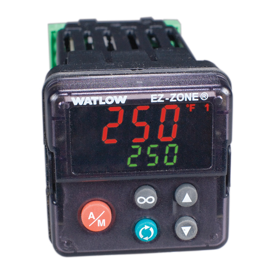
PID Controller Models
0600-0058-0000 Rev. F
July 2009
EZ-ZONE
User's Manual
1241 Bundy Boulevard., Winona, Minnesota USA 55987
Phone: +1 (507) 454-5300, Fax: +1 (507) 452-4507 http://www.watlow.com
®
PM
TOTAL
CUS S T T O O M M ER
CU
ER
S S A A TIS
TISF F A A CT
CTI I O O N N
3 Y ear Warranty
ISO 9001
ISO 9001
Registered Company
Winona, Minnesota USA
Made in the U.S.A.
$8.00
Advertisement
Table of Contents

Related Manuals for Watlow Ez-Zone PM6


Summary of Contents for Watlow Ez-Zone PM6
- Page 1 CTI I O O N N 3 Y ear Warranty ISO 9001 ISO 9001 Registered Company Winona, Minnesota USA 1241 Bundy Boulevard., Winona, Minnesota USA 55987 Phone: +1 (507) 454-5300, Fax: +1 (507) 452-4507 http://www.watlow.com 0600-0058-0000 Rev. F Made in the U.S.A. July 2009 $8.00...
- Page 2 Since Watlow has no control over their use, and sometimes misuse, we cannot guarantee against failure. Wat- Do not throw in trash, use proper recycling techniques or consult low’s obligations hereunder, at Watlow’s option, are...
- Page 3 6. If the unit is unrepairable, you will receive a letter of explanation. and be given the option to have the unit returned to you at your expense or to have us scrap the unit. 7. Watlow reserves the right to charge for no trouble found (NTF) returns. ® The EZ-ZONE PM PID Controller User’s Manual is...
-
Page 4: Table Of Contents
Table of Contents Chapter 1: Overview . . . . . . . . . . . . . . . . . . . . . . . . . . . . . . . . . . . . .2 Standard Features and Benefits . -
Page 5: Chapter 1: Overview
PM takes the pain out of solving Agency approvals: UL Listed, CSA, CE, RoHS, W.E.E.E. FM your thermal loop requirements. Watlow’s EZ-ZONE PM controllers offer options • Assures prompt product acceptance to reduce system complexity and the cost of control- • Reduces end product documentation costs loop ownership. -
Page 6: Instance
A Conceptual View of the PM Keep in mind that a function is a user-programmed internal process that does not execute any action out- The flexibility of the PM’s software and hardware al- side of the controller. To have any effect outside of the lows a large range of configurations. - Page 7 EZ-ZONE ® PM PID Model System Diagram Universal Sensor Input, Configuration Communications, Red/Green 7-Segment Display Output Input Functions Functions off, heat, cool, Output 1 none, switched dc/open collect- duplex, alarm, or, form C mechanical (5 A) relay, form A Analog Input 1 Controller retransmit, none, Thermocouple, RTD (100Ω,...
-
Page 8: Chapter 2: Install And Wire
Chapter 2: Install and Wire Dimensions 1/32 DIN 15.9 mm 0.63 in 53.3 mm 101.6 mm 2.10 in 4.00 in 31.2 mm 30.9 mm 1.23 in 1.22 in Side Front 45.2 mm (1.78 in) Recommended panel spacing panel thickness 1.53 to 9.52 mm (0.060 to 0.375) 22.4 mm (0.88 in) - Page 9 Dimensions 1/16 DIN 15.8 mm (0.62 in) 101.6 mm 53.3 mm (4.00 in) (2.10 in) 53.3 mm (2.10 in) Side Front 51.2 mm (2.02 in) Back 45.2 mm (1.78 in) Recommended panel spacing 45.2 mm (1.78 in) panel thickness 1.53 to 9.52 mm (0.060 to 0.375) 21.6 mm (0.85 in)
- Page 10 1/8 DIN (PM8) Vertical Dimensions 15.75 53.34 2.10 1.52 100.33 3.95 10.16 30.73 54.86 1.21 2.16 101.60 4.00 1/8 DIN (PM8) Vertical Recommended Panel Spacing 45.2 mm (1.78 in) 92.3 mm (3.635 in) 21.6 mm Panel thickness (0.060 in) 1.53 mm (0.85 in) to (0.375 in) 9.52 mm 21.6 mm...
- Page 11 1/8 DIN (PM9) Horizontal Dimensions 15.75 mm (0.62 in) 1.52 mm 100.33 mm (0.06 in) (3.95 in) 54.86 mm (2.16 in) 53.34 mm (2.10 in) 10.16 mm (0.40 in) 30.73 mm (1.21 in) 101.60 mm (4.00 in) 1/8 DIN (PM9) Horizontal Recommended Panel Spacing 92.3 mm (3.635 in) 45.2 mm...
- Page 12 1/4 DIN (PM4) Dimensions 15.75 100.33 3.95 1.52 100.33 3.95 12.70 30.73 1.21 100.84 3.97 1/4 DIN (PM4) Recommended Panel Spacing 92.3 3.635 92.3 3.635 21.6 Panel thickness .060 (1.53) to .375 (9.52) 21.6 Wat lo w EZ-ZO N E ®...
- Page 13 Installation Don't be afraid to apply enough pressure to prop- erly install the controller. The seal system is panel compressed more by mating the mounting collar bezel retention collar tighter to the front panel (see pictures above). If gasket you can move the case assembly back and forth in the cutout, you do not have a proper seal.
- Page 14 slide back in do not force it . Check the orientation again and reinsert after correcting . 2. Using your thumbs push on either side of the con- troller until both latches click. Chemical Compatibility This product is compatible with acids, weak alkalis, alcohols, gamma radiation and ultraviolet radiation.
- Page 15 Terminal Definitions for Slots A Slot A Output Terminal Function Configuration common (Any switched dc output can use this common.) Switched dc/open collector dc- (open collector) output 1: PM _ _ _ C _-_ AAAA _ _ Switched dc output 2: PM _ _ _ _ C-_ AAAA _ _ voltage or current - Universal Process voltage +...
- Page 16 Back View Back View Slot Orientation 1/8 Slot Orientation DIN Vertical PM8 1/8 DIN Horizontal PM9 Back View Slot Orientation 1/4 DIN Horizontal PM4 EZ-ZONE PM Isolation Blocks Digital Inputs & Outputs No Isolation Controller Power Supply 12 to 40VÎ (dc) Safety Isolation 20 to...
- Page 17 Low Power Óç Slot C power Warning: fuse power Use National Electric (NEC) • Minimum/Maximum Ratings or other country-specific • 12 to 40VÎ (dc) standard wiring and safety • 20 to 28VÅ (ac) Semi Sig F47 • 47 to 63 Hz practices when wiring and • 14VA maximum power consumption (PM4,8 & 9) connecting this controller to • 10VA maximum power consumption (PM3 & 6) a power source and to elec- PM_ _ [3,4] _ _ - _ _ _ _ _ _ _...
- Page 18 Input 1 Thermocouple Óç Slot A Warning: • 2 kΩ maximum source resistance Use National Electric (NEC) • >20 MΩ input impedance or other country-specific • 3 microampere open-sensor detection standard wiring and safety • Thermocouples are polarity sensitive. The negative lead (usually practices when wiring and red) must be connected to S1. connecting this controller to • To reduce errors, the extension wire for thermocouples must be a power source and to elec- of the same alloy as the thermocouple.
- Page 19 Input 1 Thermistor Óç Slot A Warning: Use National Electric (NEC) • >20 MΩ input impedance or other country-specific • 3 microampere open-sensor detection Input 1: PM _ [J,N,E*] _ _ _ _-_ _ _ _ _ _ _ (S1/ standard wiring and safety practices when wiring and connecting this controller to *PM4,8 & 9 only a power source and to elec-...
- Page 20 Digital Output 5, 6 Óç Slot C Digital Output Warning: • Update rate 10 Hz Use National Electric (NEC) • Output voltage 24V • Current limit, Output 5, 24 or other country-specific mA maximum standard wiring and safety • Current limit, Output 6, practices when wiring and 10 mA maximum driving connecting this controller to single pole DIN-A-MITE a power source and to elec- • Capable of driving a 3-pole...
- Page 21 Output 1 Universal Process Óç Slot A • 0 to 20 mA into 800 Ω maxi- volts or current - Warning: negative mum load volts + Use National Electric (NEC) • 0 to 10VÎ (dc) into voltage 1 0 to 10 V or other country-specific current + kΩ minimum load standard wiring and safety • scalable 4 to 20 mA...
- Page 22 Output 2 NO-ARC Relay, Form A Óç Slot A • 15 A at 85 to 264VÅ (ac) resis- Warning: tive load only Use National Electric (NEC) • 1/16 DIN models only or other country-specific • 2,000,000 cycle rating for NO- standard wiring and safety ARC circuit normally open practices when wiring and • 100 mA minimum load common • 2 mA maximum off state leakage...
- Page 23 Quencharc Wiring Example Óç In this example the Quencharc circuit (Watlow User Load part# 0804-0147-0000) is used to protect PM Warning: internal circuitry from the counter electro- Use National Electric (NEC) Quencharc magnetic force from the inductive user load or other country-specific when de-engergized.
- Page 24 . controller on network. Modbus RTU or Note: Standard Bus EIA-485 To prevent damage to the Modbus-IDA EIA/TIA-485 Watlow Termi- Function controller, do not connect Terminal Name nal Label wires to unused terminals . CA or CD...
- Page 25 A Network Using Watlow's Standard Bus and an RUI/Gateway Óç Power EZ-ZONE ST Supply Warning: ST_ _ - (B or F) _ M _ -_ _ _ _ Use National Electric (NEC) EZ-ZONE RM or other country-specific fuse standard wiring and safety...
-
Page 26: Chapter 3: Keys And Displays
Chapter 3: Keys and Displays Lower (Right, 32 DIN) Dis- 1/32 DIN (PM3) Upper (Left, 32 DIN) Display: play: In the Home Page, displays the process ® Indicates the set point or output value, otherwise displays the value of power value during operation, or the parameter in the lower display. - Page 27 Responding to a Displayed Message lencing enabled it can be silenced simply by pushing the Infinity ˆ key. Alternatively, use the method be- An active message will cause the display to toggle be- low to view all and then clear. tween the normal settings and the active message in Push the Advance Key to display [ignr] in the up- the upper display and [Attn] in the lower display.
-
Page 28: Chapter 4: Home
Chapter 4: Home Page Default Home Page Parameters Watlow’s patented user-defined menu system im- Active Process Value [aC ; p u] will be displayed on top proves operational efficiency. The user-defined Home and Parameter [`par] in the bottom. Using the Up Page provides you with a shortcut to monitor or ¿... - Page 29 Home Page Home Page Defaults Parameter Page and Menu Display All Models Numerical Active Process Value (1) Operations Page, Monitor Menu value Numerical Active Set Point (1) Operations Page, Monitor Menu value User Control Mode (1) Operations Page, Monitor Menu [C;...
- Page 30 Navigating the EZ-ZONE PM PID Controller ® Applies to All Models - 1/16 DIN Shown Below ® ® ® ® [``Ai] [``70] [``70] [Cust] [``72] [fCty] [`Set] [``72] Home Page from anywhere: Press the Infinity Factory Page from Home Page: Press both the Key ˆ...
-
Page 31: Conventions Used In The Menu
RWES = Readable tion does not dictate which register should be high Writable or low order Watlow provides the user the ability to swap this order (Setup Page, Com Menu) from the EEPROM (saved) default low/high [lohi] to high/low [ hilo] . - Page 32 To learn more about the RUI/GTW point your browser to the link below and search for keyword EZ- ZONE. http://www.watlow.com/literature/pti_search.cfm Wa t low EZ-ZO N E ® P M P ID Co n t r o l le r Chapter 4 Home Pa ge •...
-
Page 33: Chapter 5: Operations
Chapter 5: Operations Page Navigating the Operations Page To go to the Operations Page from the Home Page, • Press the Up ¿ or Down ¯ key to move through press both the Up ¿ and Down ¯ keys for three sec- available menu prompts. onds. -
Page 34: Table Of Contents
Operations Page Data Parameter Type Class Parameter name Modbus Rela- Profibus Display Range Default Appears in & Instance Description tive Address Index Menu When Read/ Attribute Write hex (dec) [``Ai] [oPEr] Analog Input Menu Analog Input (1) -1,999.000 to Always Instance 1 0x68 (104) float... - Page 35 Operations Page Data Parameter Type Class Parameter name Modbus Rela- Profibus Display Range Default Appears in & Instance Description tive Address Index Menu When Read/ Attribute Write hex (dec) Instance 1 - - - - uint Linearization (1) None (61) 0x86 (134) Output Error Open (65)
- Page 36 Operations Page Data Parameter Type Class Parameter name Modbus Rela- Profibus Display Range Default Appears in & Instance Description tive Address Index Menu When Read/ Attribute Write hex (dec) [`dio] [oPEr] Digital Input/ Output Menu Digital Output (5 to 6) [`off] Off (62) Direction Instance 1...
- Page 37 Operations Page Data Parameter Type Class Parameter name Modbus Rela- Profibus Display Range Default Appears in & Instance Description tive Address Index Menu When Read/ Attribute Write hex (dec) Monitor (1) -100.0 to 0.0% Cool algo- Instance 1 0x97 (151) - - - - float [`C;...
- Page 38 Operations Page Data Parameter Type Class Parameter name Modbus Rela- Profibus Display Range Default Appears in & Instance Description tive Address Index Menu When Read/ Attribute Write hex (dec) Instance 1 Loop (1) Low Set Point to High 75.0°F Always 0x6B (107) float [`id;...
- Page 39 Operations Page Data Parameter Type Class Parameter name Modbus Rela- Profibus Display Range Default Appears in & Instance Description tive Address Index Menu When Read/ Attribute Write hex (dec) Instance 1 Loop (1) -1,000.0 to 1,000.0°F Always 0x97 (151) float [``dB] Dead Band [ db] or units Map 1...
- Page 40 Operations Page Data Parameter Type Class Parameter name Modbus Rela- Profibus Display Range Default Appears in & Instance Description tive Address Index Menu When Read/ Attribute Write hex (dec) Instance 1 Alarm (1 to 4) Startup (88) None No param- 0x6D - - - - uint...
- Page 41 Operations Page Data Parameter Type Class Parameter name Modbus Rela- Profibus Display Range Default Appears in & Instance Description tive Address Index Menu When Read/ Attribute Write hex (dec) Instance 1 Profile Status [nonE] None (61) None Always 0x7A (122) uint [P;...
- Page 42 Operations Page Data Parameter Type Class Parameter name Modbus Rela- Profibus Display Range Default Appears in & Instance Description tive Address Index Menu When Read/ Attribute Write hex (dec) 0 to 9,999.000 seconds Always Instance 1 0x7A (122) - - - - float Profile Status [`S;...
- Page 43 Operations Page Data Parameter Type Class Parameter name Modbus Rela- Profibus Display Range Default Appears in & Instance Description tive Address Index Menu When Read/ Attribute Write hex (dec) Instance 1 Profile Status 0x7A (122) - - - - uint Current File Map 1 Map 2...
-
Page 44: Chapter 6: Setup
Chapter 6: Setup Page Navigating the Setup Page To go to the Setup Page from the Home Page, press • Press the Up ¿ or Down ¯ key to move through both the Up ¿ and Down ¯ keys for six seconds. available menu prompts. [``Ai] will appear in the upper display and [`Set] • Press the Infinity Key ˆ... - Page 45 [`A; S D] Sides [`a; L A] Latching [`A; b L] Blocking [`a; S i] Silencing [A; d sp] Display [`A; d L] Delay [`fUn] [`Set] Function Key Menu [```1] to [```2] [`fUn] Function Key [`leu] Level [``Fn] Digital Input Function [``fi] Instance [gLbL] [`Set] Global Menu...
- Page 46 Setup Page Data Parameter Modbus Rela- Type Class Dis- Parameter name Appears Profibus Range Default tive & Instance play Description in Menu Index Address Read/ Attribute When Write hex (dec) [``Ai] [`Set] Analog Input Menu Instance 1 Analog Input (1) [`oFF] Off (62) Always 0x68 (104)
- Page 47 Setup Page Data Parameter Modbus Rela- Type Class Dis- Parameter name Appears Profibus Range Default tive & Instance play Description in Menu Index Address Read/ Attribute When Write hex (dec) Analog Input (1) -100.0 to 1,000.0 20.0 Sensor Type Instance 1 0x68 (104) float [`S;...
-
Page 48: Ber Digit
Setup Page Data Parameter Modbus Rela- Type Class Dis- Parameter name Appears Profibus Range Default tive & Instance play Description in Menu Index Address Read/ Attribute When Write hex (dec) Instance 1 float Analog Input (1) 0.0 to 60.0 seconds Always 0x68 (104) [`FiL]... - Page 49 Setup Page Data Parameter Modbus Rela- Type Class Dis- Parameter name Appears Profibus Range Default tive & Instance play Description in Menu Index Address Read/ Attribute When Write hex (dec) Instance 1 Linearization (1) -1,999.000 to 9,999.000 Always 0x86 (134) float [`iP;...
- Page 50 Setup Page Data Parameter Modbus Rela- Type Class Dis- Parameter name Appears Profibus Range Default tive & Instance play Description in Menu Index Address Read/ Attribute When Write hex (dec) Linearization (1) -1,999.000 to 9,999.000 Always Instance 1 0x86 (134) float [`oP;...
- Page 51 Setup Page Data Parameter Modbus Rela- Type Class Dis- Parameter name Appears Profibus Range Default tive & Instance play Description in Menu Index Address Read/ Attribute When Write hex (dec) Process Value (1) 0.0 to 60.0 seconds Always Instance 1 0x7E (126) - - - - float...
- Page 52 Setup Page Data Parameter Modbus Rela- Type Class Dis- Parameter name Appears Profibus Range Default tive & Instance play Description in Menu Index Address Read/ Attribute When Write hex (dec) Digital Output (5 to 6) [ 0.1 for Fast and Bi-Di- Control Instance 1 0x6A (106)
- Page 53 Setup Page Data Parameter Modbus Rela- Type Class Dis- Parameter name Appears Profibus Range Default tive & Instance play Description in Menu Index Address Read/ Attribute When Write hex (dec) Direction is Instance 1 0x6E (110) uint Digital Input (5 to 6) [none] None (61) [``Fn] Action Function...
- Page 54 Setup Page Data Parameter Modbus Rela- Type Class Dis- Parameter name Appears Profibus Range Default tive & Instance play Description in Menu Index Address Read/ Attribute When Write hex (dec) Control Loop (1) [`oFF] Off (62) Cool Algo- Instance 1 0x97 (151) - - - - uint...
- Page 55 Setup Page Data Parameter Modbus Rela- Type Class Dis- Parameter name Appears Profibus Range Default tive & Instance play Description in Menu Index Address Read/ Attribute When Write hex (dec) Control Loop (1) [`oFF] Off, sets output User Always Instance 1 0x6B (107) - - - - uint...
- Page 56 Setup Page Data Parameter Modbus Rela- Type Class Dis- Parameter name Appears Profibus Range Default tive & Instance play Description in Menu Index Address Read/ Attribute When Write hex (dec) Open Loop Instance 1 0x97 (151) float Control Loop (1) -1,999.000 to 9,999.000°F 10.0°F or [`L;...
- Page 57 Setup Page Data Parameter Modbus Rela- Type Class Dis- Parameter name Appears Profibus Range Default tive & Instance play Description in Menu Index Address Read/ Attribute When Write hex (dec) [otpt] [`Set] Output Menu Output Digital (1 to 2) [`oFF] Off (62) Output 1 - Instance 1 0x6A (106)
- Page 58 Setup Page Data Parameter Modbus Rela- Type Class Dis- Parameter name Appears Profibus Range Default tive & Instance play Description in Menu Index Address Read/ Attribute When Write hex (dec) Output (1 to 2) 0.0 to 100.0% 100.0% Source is Instance 1 0x6A (106) float...
- Page 59 Setup Page Data Parameter Modbus Rela- Type Class Dis- Parameter name Appears Profibus Range Default tive & Instance play Description in Menu Index Address Read/ Attribute When Write hex (dec) Output (1 process) -1,999.000 to 9,999.000°F 0.0°F or Always if Instance 1 0x76 (118) float [`r;...
- Page 60 Setup Page Data Parameter Modbus Rela- Type Class Dis- Parameter name Appears Profibus Range Default tive & Instance play Description in Menu Index Address Read/ Attribute When Write hex (dec) Type is not Instance 1 0x6D (109) float Alarm (1 to 4) 0.001 to 9,999.000°F or 1.0°F or [`A;...
- Page 61 Setup Page Data Parameter Modbus Rela- Type Class Dis- Parameter name Appears Profibus Range Default tive & Instance play Description in Menu Index Address Read/ Attribute When Write hex (dec) Instance 1 0x6D (109) uint Alarm (1 to 4) [`oFF] Off (62) Type is not [`A;...
- Page 62 Setup Page Data Parameter Modbus Rela- Type Class Dis- Parameter name Appears Profibus Range Default tive & Instance play Description in Menu Index Address Read/ Attribute When Write hex (dec) None Always Instance 1 0x6E (110) uint Function Key (1 to 2) [none] None (61) [``Fn] 1 to 2...
- Page 63 Setup Page Data Parameter Modbus Rela- Type Class Dis- Parameter name Appears Profibus Range Default tive & Instance play Description in Menu Index Address Read/ Attribute When Write hex (dec) Time Always Instance 1 0x7A (122) - - - - uint Profile [rate] Rate (81)
- Page 64 Setup Page Data Parameter Modbus Rela- Type Class Dis- Parameter name Appears Profibus Range Default tive & Instance play Description in Menu Index Address Read/ Attribute When Write hex (dec) Instance 1 Communications (1) 1 to 247 Protocol 0x96 (150) - - - - uint [Ad;...
- Page 65 Setup Page Data Parameter Modbus Rela- Type Class Dis- Parameter name Appears Profibus Range Default tive & Instance play Description in Menu Index Address Read/ Attribute When Write hex (dec) Instance 1 Real Time Clock 0 to 59 Always if 88 (136) - - - - uint...
-
Page 66: Chapter 7: Profiling
Chapter 7: Profiling Page Navigating the Profiling Page Note: Some of these menus and parameters may not appear, depending on the controller's options. See model number information in the Appendix for more information. If there is only one instance of a menu, no submenus will appear. How to Start a Profile The Profiling Page allows you to enter your ramp and soak profile information. - Page 67 Profiling Page Dis- Parameter name Range Default Parameter Modbus Data play Description Appears in Relative Ad- Type Class Menu When dress & Instance Read/ Attribute Write hex (dec) [``P1] [prof] Profiling Menu Step 1 to 10 [profile 1] Always [``p1] [ P1] to Select a step to edit or view.
- Page 68 Profiling Page Dis- Parameter name Range Default Parameter Modbus Data play Description Appears in Relative Ad- Type Class Menu When dress & Instance Read/ Attribute Write hex (dec) 0 to 59 Step Type Parameters Step Type is Instance 1 0x79 (121) uint [~SEC] [ SEC]...
- Page 69 Profiling Page Dis- Parameter name Range Default Parameter Modbus Data play Description Appears in Relative Ad- Type Class Menu When dress & Instance Read/ Attribute Write hex (dec) Step Type Parameters 0 to 9,999 Step Type is Instance 1 0x79 (121) uint [~~JC] [ JC]...
-
Page 70: Chapter 8: Factory
Chapter 8: Factory Page Navigating the Factory Page To go to the Factory Page from the Home Page, • Press the Up ¿ or Down ¯ keys to change the press and hold both the Advance and Infinity ˆ parameter value. keys for six seconds. • Press the Infinity Key ˆ... - Page 71 Factory Page Modbus Profibus Data Parameter Relative Ad- Index Type Class Dis- Parameter name Range Default Appears in dress & Instance play Description Menu When Read/ Attribute Write hex (dec) [Cust] [fcty] Custom Menu Custom Menu [nonE] None See: Always - - - - - - - - - - - -...
- Page 72 Factory Page Modbus Profibus Data Parameter Relative Ad- Index Type Class Dis- Parameter name Range Default Appears in dress & Instance play Description Menu When Read/ Attribute Write hex (dec) [`LoC] [FCty] Security Setting Menu Security Setting 1 to 3 Always - - - - - - - -...
- Page 73 Factory Page Modbus Profibus Data Parameter Relative Ad- Index Type Class Dis- Parameter name Range Default Appears in dress & Instance play Description Menu When Read/ Attribute Write hex (dec) Security Setting [`off] Off Always - - - - - - - - - - - - - - - - [roll]...
- Page 74 Factory Page Modbus Profibus Data Parameter Relative Ad- Index Type Class Dis- Parameter name Range Default Appears in dress & Instance play Description Menu When Read/ Attribute Write hex (dec) Diagnostics Menu 0 to 2,147,483,647 - - - - 0x65 (101) - - - - string [``Sn]...
- Page 75 Factory Page Modbus Profibus Data Relative Ad- Parameter Index Type Class Dis- Parameter name Range Default Appears in dress & Instance play Description Menu When Read/ Attribute Write hex (dec) [`CAL] [FCty] Calibration Menu Calibration Menu (1 -3.4e38 to 3.4e38 Always Instance 1 0x68 (104)
-
Page 76: Chapter 9: Features
Chapter 9: Features Saving and Restoring User Settings . . . . . . . . . . . . . . . . . . . . . . . . . . 74 Programming the Home Page . - Page 77 Autotune Set Point [A; t SP] (Operations Page, Loop Menu) is set to 90 percent, the autotune function utilizes 180° for tuning. This is also how autotun- ing works in previous Watlow Winona controllers. In addition, changing the active set point in previous controllers causes the autotune function to restart;...
- Page 78 Manual Tuning The preferred and quickest method for tuning a loop is to establish initial control settings and contin- In some applications, the autotune process may not ue with the adaptive mode to fine tune the settings. provide PID parameters for the process characteris- Setting a controller's control mode to tune starts tics you desire.
- Page 79 When autotuning is complete, the PID parameters Follow these steps for a thermocouple or pro- cess input: should provide good control. As long as the loop is in the adaptive control mode, TRU-TUNE+ continu- ® 1. Apply the low source signal to the input you are ously tunes to provide the best possible PID control calibrating.
- Page 80 Filter Time Constant Scale High and Scale Low Filtering smoothes an input signal by applying a When an analog input is selected as process voltage first-order filter time constant to the signal. Filter- or process current input, you must choose the value ing the displayed value makes it easier to monitor.
- Page 81 Range Low Scale Low Scale High The Watlow NO-ARC relay is a hybrid relay. It us- Retransmit Source es a mechanical relay for the current load and a triac Retransmit Set the range of the process output with Scale (solid-state switch) to carry the turn-on and turn-off Low [`S;...
- Page 82 is present, the controller will perform closed-loop con- trol. Closed-loop control uses a process sensor to de- termine the difference between the process value and the set point. Then the controller applies power to a control output load to reduce that difference. If a valid input signal is not present, the control- ler will indicate an input error message in the upper display and [Attn] in the lower display and respond...
- Page 83 Proportional Control [MAn] for manual mode. Use the Up ¿ or Down ¯ keys to select [AUto]. The automatic set point value Some processes need to maintain a temperature or will be recalled from the last automatic operation. process value closer to the set point than on-off con- Changes take effect after three seconds or imme- trol can provide.
- Page 84 Proportional plus Integral plus Derivative (PID) Control Use derivative (rate) control to minimize the over- shoot in a PI-controlled system. Derivative (rate) ad- Cool Output Active Set Point justs the output based on the rate of change in the Heat Output Active temperature or process value.
- Page 85 fect of analog, phase-angle fired control. Select the AC Line Frequency [AC; L F] (Setup Page, Global Menu), 50 or 60 Hz. Set Point 100 percent output Temperature reaches Set Point quickly 10 ON, 0 OFF Time Heating System without Ramping Set Point 50 percent output degrees...
- Page 86 View or change alarm set points with Low Set The alarm state begins when the temperature Point [`A; L o] and High Set Point [`A; h i] (Operations reaches the Alarm High Set Point Page, Alarm Menu). Alarm High Set Point Alarm Hysteresis Alarm Hysteresis An alarm state is triggered when the process value...
-
Page 87: Using Lockout To Hide Pages And Menus
ZONE Configurator, using a personal computer. put Function and a Function Instance. If you want to start and stop a profile with the EZ The following examples show how to program the Key, select Profile Start/Stop and the number of the EZ Key to start and stop a profile. -
Page 88: Using Password Security
In the Factory Page, Lockout Menu, set Read Lockout Security [SLoC] & [rloC] Lockout Security [rLoC] to 1 and Set Lockout Lockout Level Security [SLoC] to 5. Home Page In the Factory Page, Lockout Menu, set Lock Operations Page [LoC; O ] to 2 and Lock Profiling Operations Page Page [LoC;... - Page 89 Note: - A User with a password is restricted by the Read Lockout Security [rloC] never having ac- If Password Security (Password Enabled [ pas ; e ] cess to the Lock Menu [`loC] . is On) is enabled the two prompts mentioned below in the first step will not be visible.
-
Page 90: Chapter 10: Appendix
Chapter 10: Appendix Troubleshooting Alarms, Errors and Control Issues Indication Description Possible Causes Corrective Action Alarm won’t clear or reset Alarm will not clear or reset • Alarm latching is active • Reset alarm when process is with keypad or digital input within range or disable latching • Alarm set to incorrect output • Set output to correct alarm source instance • Alarm is set to incorrect • Set alarm source to correct in-... - Page 91 Open Loop Detect is active and • Setting of Open Loop Detect • Set correct Open Loop Detect [LP; o 1] the process value did not devi- Time incorrect Time for application Loop Open Error ate by a user-selected value in • Setting of Open Loop Detect • Set correct Open Loop Devia- a user specified period. Deviation incorrect tion value for application • Thermal loop is open • Determine cause of open ther- mal loop: misplaced sensors,...
- Page 92 Indication Description Possible Causes Corrective Action Process doesn’t control to set Process is unstable or never • Controller not tuned correctly • Perform autotune or manually point reaches set point tune system • Control mode is incorrectly set • Set control mode appropriately (Open vs Closed Loop) • Control set point is incorrect • Set control set point in appro- priate control mode and check source of set point: remote, idle, profile, closed loop, open loop Temperature runway Process value continues to in-...
-
Page 93: Specifications
Specifications ance; scalable, 0-50mV, 0-1000Ω •Potentiometer: 0 to 1,200Ω LineVoltage/Power (Minimum /Maximum Ratings) •Inverse scaling •85 to 264V~ (ac), 47 to 63Hz •20 to 28VÅ (ac), 47 to 63Hz Accuracy Accuracy Error •12 to 40VÎ (dc) Input Type Range Range Units @ 25 •14VA maximum power consumption (PM4, 8 & 9) High Deg C •10VAmaximum power consumption (PM3 & 6) •Data retention upon power failure via nonvolatile memory ±1.75 Deg C •Compliant with SEMIF47-0200,FigureR1-1 voltage sag require- ±2.45 -200 1250 Deg C ments @24V ~ (ac) or higher T (0 to 350) ±1.55... - Page 94 Dimensions Operating Range Dimensions RTD (1000 ohm) -200 Size Behind Width Height Display Character Panel Height Volts (max.) mAdc left: 7.59 mm (0.299 mAac 101.6 mm 53.3 mm 30.9 mm 1/32 (4.00 in) (2.10 in) (1.22 in) right: 5.90 mm (0.220 Potentiometer, 1K range 1200 Resistance, 5K range...
-
Page 95: Ordering Information For Pid Controller Models
Ordering Information for PID Controller Models Controller P M __ __ __ __ __ - __ A A A A __ __ ® EZ-ZONE PID Controller Models ® TRU-TUNE+ Adaptive Tune, red-green 7-segment displays Package Size Panel Mount 1/32 DIN Panel Mount 1⁄16 DIN Panel Mount 1⁄8 DIN Vertical Panel Mount 1⁄8 DIN Horizontal... -
Page 96: Index
Index [`A; b L] Alarm Blocking 57, 83 [`dir] Direction 48 [``JC] Jump Count Remaining 39 [AC; L F] AC Line Frequency 59, 82 [`do; S ] Digital Output State 33 [``JS] Jump Step 65 [`A; d L] Alarm Delay 58 [dow] Day of Week 62 [`L;... - Page 97 changing the set point 25 [pas; e ] Password Enable 67, 69 [``ti] Time Integral 35, 75, 80 Channel Action 67 [pass] Password 70 [t; t Un] TRU-TUNE+™ Enable 51, [Pass] Password 67 chattering output 80 [pas; u ], User Password 85 [tUn1] Tuning 24 chemical compatibility 11 Closed Loop Set Point 34...
- Page 98 Direction 48 Input Point 5 41 Display 58 Input Point 6 41 on-off control 80 Display Pairs 67 Input Point 7 41 Open Loop Detect Deviation 53 displays 23 Input Point 8 41 Open Loop Detect Enable 52 Display Units 59 Input Point 9 41 Open Loop Detect Time 52 Down Key 23...
- Page 99 Ramp Scale 53, 82 User Password 67, 70 Range High 44, 56, 77 User Restore Set 71, 74 Range Low 44, 56, 77 User Save Set 71, 74 Read Lockout Security 84 User Tune Aggressiveness 74 Real Time Clock 28, 42 using the software 84 Relative Humidty 45 Relative Temperature 45...
- Page 100 Declaration of Conformity ® Series EZ-ZONE WATLOW ISO 9001 approved facility since 1996. 1241 Bundy Blvd. Winona, MN 55987 USA Declares that the following product: ® Designation: Series EZ-ZONE PM (Panel Mount) Model Numbers: PM (3, 6, 8, 9 or 4)(Any Letter or number) – (1, 2, 3 or 4)(A, C, E, F or K) (A, C, H, J or K)(Any letter or number) –...
- Page 101 Postfach 11 65, Lauchwasenstr. 1 Latin America Linby, Nottingham, NG15 8AA D-76709 Kronau United Kingdom Watlow de México S.A. de C.V. Germany Telephone: (0) 115 964 0777 Av. Fundición No. 5 Tel: +49 (0) 7253 9400-0 Fax: (0) 115 964 0071 Col.
Need help?
Do you have a question about the Ez-Zone PM6 and is the answer not in the manual?
Questions and answers