Table of Contents
Advertisement
GETTING STARTED GUIDE AND SPECIFICATIONS
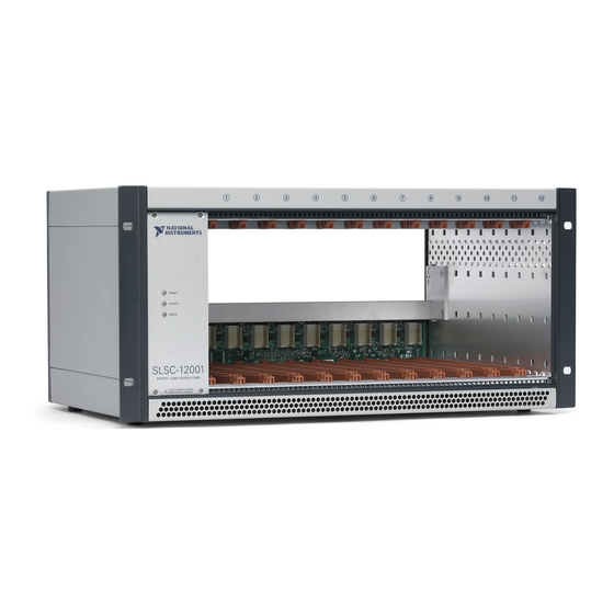
SLSC-12001 Chassis
12 Slot Switch Load Signal Conditioning Chassis for 4U SLSC Modules
This document describes how to get started with the National Instruments SLSC-12001 chassis.
The document contains chassis specifications, information about installing and mounting
hardware, and powering and connecting the chassis.
Contents
Electromagnetic Compatibility Guidelines .............................................................................. 2
Unpacking the Chassis.............................................................................................................. 3
What You Need to Get Started ................................................................................................. 3
Chassis Overview ..................................................................................................................... 4
SLSC-12001 Chassis Block Diagram............................................................................... 6
SLSC-12001 Chassis Rear Transition Interface ............................................................... 7
Installing the Chassis ................................................................................................................ 8
Installing Rear Transition Interfaces ........................................................................................ 9
Installing SLSC Modules.......................................................................................................... 9
Removing SLSC Modules ........................................................................................................ 10
Connecting the Chassis............................................................................................................. 11
Safety Guidelines.............................................................................................................. 11
Grounding the Chassis...................................................................................................... 11
Wiring Power to the Chassis ............................................................................................ 11
Powering on the Chassis................................................................................................... 12
Connecting the Chassis to a Host ..................................................................................... 13
Connecting to a Measurement System ............................................................................. 13
Maintenance.............................................................................................................................. 13
Cleaning the Chassis......................................................................................................... 13
Cleaning and Replacing the Chassis Intake Filter ............................................................ 14
Cleaning the Filter .................................................................................................... 14
Removing the Filter .................................................................................................. 14
Inserting the Filter .................................................................................................... 14
Fan Maintenance............................................................................................................... 15
Fan Replacement ...................................................................................................... 16
Battery Replacement......................................................................................................... 19
Troubleshooting........................................................................................................................ 21
Understanding LED Indicators......................................................................................... 21
Network Communication Troubleshooting ...................................................................... 21
Resetting the Chassis and Modules .................................................................................. 22
Fan Faults ......................................................................................................................... 22
Module Short Circuit Behavior ........................................................................................ 22
Advertisement
Table of Contents

Related Manuals for National Instruments SLSC-12001


Summary of Contents for National Instruments SLSC-12001
-
Page 1: Table Of Contents
SLSC-12001 Chassis 12 Slot Switch Load Signal Conditioning Chassis for 4U SLSC Modules This document describes how to get started with the National Instruments SLSC-12001 chassis. The document contains chassis specifications, information about installing and mounting hardware, and powering and connecting the chassis. -
Page 2: Electromagnetic Compatibility Guidelines
Furthermore, any modifications to the product not expressly approved by National Instruments could void your authority to operate it under your local regulatory rules. -
Page 3: Unpacking The Chassis
Retain the packing material for possible inspection and/or reshipment. If the chassis is damaged, do not install it and contact NI. What You Need to Get Started To set up and use the SLSC-12001 chassis you need the following items: • Hardware –... -
Page 4: Chassis Overview
Chassis Overview The SLSC-12001 chassis is designed for use with any SLSC module designed in accordance with the SLSC Module Design Specification 1.0. The SLSC-12001 chassis must be powered by an external power supply as described in the Chassis Power section of this document. - Page 5 Rear Air Exhaust Button Upper Rear Panel Screws (4) Ethernet Port Upper Rear Panel 10 Chassis Ground Screw Bumpers (2) 11 DC Voltage Input Trigger 0 12 Backplane Panel SLSC-12001 Chassis Getting Started Guide and Specifications | © National Instruments | 5...
-
Page 6: Slsc-12001 Chassis Block Diagram
The SLSC-12001 chassis communicates with each module through the SLSC interface and manages the Ethernet connectivity with a host computer. The SLSC-12001 chassis also has built-in diagnosis functions, such as battery and fan monitoring, that is accessible through the NI-SLSC driver. The chassis will shut down the 24 V rail supplied to the module unless all 5 fans are powered. -
Page 7: Slsc-12001 Chassis Rear Transition Interface
SLSC-12001 Chassis Rear Transition Interface An optional secondary backplane, RTI, may be used with the SLSC-12001 chassis to route conditioned I/O signals directly to the DAQ system. The RTI can be used to distribute additional power to one or more modules as shown in Figure 4. -
Page 8: Installing The Chassis
IEC 61010-1 for containing the potential spread of fire from the RTIs. The SLSC-12001 chassis cooling inlet air vents are located on the front lower side of the chassis and the outlet air vents are on the back upper side of the chassis. Position the air inlet to pull air from outside the instrument rack. -
Page 9: Installing Rear Transition Interfaces
Ensure that the chassis is powered off. The POWER LED should be off. If it is not off, do not proceed until the POWER LED is off. SLSC-12001 Chassis Getting Started Guide and Specifications | © National Instruments | 9... -
Page 10: Removing Slsc Modules
Module Injector/Ejector Handle Removing SLSC Modules The SLSC-12001 chassis and the SLSC modules do not support hot Caution plug-in. The entire chassis must be powered down when a module is removed. Complete the following steps to remove an SLSC module from the chassis: Power off the main DC power source or disconnect it from the chassis before removing the module. -
Page 11: Connecting The Chassis
Connect the grounding electrode system of the facility to the chassis using the chassis grounding screw located on the back of the SLSC-12001 chassis. Refer to Figure 2 for the location of the chassis ground screw. Use an AWG 8 wire with a lug as appropriate for your application. -
Page 12: Powering On The Chassis
The SLSC-12001 chassis can draw a significant current from the +24 V power input to support module requirements. Refer to the Physical Characteristics section for wire gauge sizes permitted by the SLSC-12001 chassis connector when wiring the power. Minimize the cable length between the power supply and SLSC-12001 chassis. -
Page 13: Connecting The Chassis To A Host
Chassis Power section. Connecting the Chassis to a Host Use a shielded Category 5 Ethernet cable to connect the SLSC-12001 using one of the following methods: By default, the SLSC-12001 uses DHCP to acquire an IP address. If the Note network to which it is connected does not have a DHCP server, the SLSC-12001 assigns itself a link-local IP address. -
Page 14: Cleaning And Replacing The Chassis Intake Filter
Cleaning the Filter A dirty intake filter dramatically affects the cooling performance of an SLSC-12001 chassis. Clean the intake filter whenever it becomes visibly dirty. For minor dust buildup, you can vacuum the intake filter without removing it from the chassis. -
Page 15: Fan Maintenance
Actual fan operating life may vary based on individual module airflow and heat dissipation characteristics. The information provided in Figure 8 allows you to maximize the performance and operation of the SLSC-12001 chassis by allowing you to manage maintenance schedules. Figure 8. Projected Fan Lifetime... -
Page 16: Fan Replacement
Fan Replacement National Instruments provides a replacement kit containing five fans and two plastic cable ties. The replacement kit is available at ni.com Fan Removal Insert a small flathead screwdriver into the small notches shown in Figure 9 to remove the side panels. - Page 17 Figure 11. Fan Terminal Block Wire Removal and Insertion Step 1 Insert the Screwdriver Step 3 Replace the Fan Terminal Block Wire Step 2 Remove the Fan Terminal Block Wire Step 4 Remove the Screwdriver SLSC-12001 Chassis Getting Started Guide and Specifications | © National Instruments | 17...
- Page 18 Reinsert the two top panel retention screws using a Phillips screwdriver and tighten the screws to a torque of 1.92 N · m (17 lb · in.). Replace the side panels. 18 | ni.com | SLSC-12001 Chassis Getting Started Guide and Specifications...
-
Page 19: Battery Replacement
Plastic Cable Tie Battery Replacement The SLSC-12001 contains a lithium cell battery that is required for storing the Real Time Clock information when the chassis is powered off. There is only a slight drain on the battery when power is applied to the SLSC-12001 power connector. The rate at which the battery drains when power is disconnected depends on the ambient storage temperature. - Page 20 Figure 15. SLSC-12001 Chassis Battery Replacement G IZ I/ O IL E Backplane Panel BNC Connector Nut (2) Backplane Panel Affixing Screws (8) Battery BNC Connector Washer (2) Chassis Power Connector 20 | ni.com | SLSC-12001 Chassis Getting Started Guide and Specifications...
-
Page 21: Troubleshooting
Troubleshooting Understanding LED Indicators The SLSC-12001 has three LEDs on the front panel. The significance of the LEDs is described in Table 2. Table 2. Troubleshooting Using LED Indicators LED Type LED Indicator Status POWER No power or short circuit on +3.3 V rail causing failure to power on. -
Page 22: Resetting The Chassis And Modules
+24 V rail to each slot is turned off to prevent system damage. Module Short Circuit Behavior Each SLSC module is powered from the SLSC-12001 through +3.3 V and +24 V rails. If a defective module is present, the SLSC-12001 may fail to start. If one SLSC module has a short circuit condition on the +3.3 V rail, the SLSC-12001 chassis will not start, there will be no... -
Page 23: Specifications
Specifications The following specifications apply to an SLSC-12001 mounted in a rack with recommended cooling clearances found in the Installing the Chassis section and using a power supply that meets the specifications provided in this Specifications section. The specifications are valid for the entire temperature range of the chassis unless otherwise specified. -
Page 24: Battery
Typical battery life with power applied to power connector..........8 years Network Network interface ..........10BASE-T, 100BASE-T, 1000BASE-T Ethernet compatibility........IEEE 802.3 Communication rates ........10 Mbps, 100 Mbps, 1,000 Mbps auto-negotiated Maximum cabling distance .......100 m/segment 24 | ni.com | SLSC-12001 Chassis Getting Started Guide and Specifications... -
Page 25: Physical Characteristics
MODULES WHILE POWERED MODULES WHILE POWERED 7.2 mm (0.28 in.) Power connector screw-terminal wire gauge............8.36 mm (8 AWG) Power connector screw-terminal wire type ............Copper conductor wire SLSC-12001 Chassis Getting Started Guide and Specifications | © National Instruments | 25... -
Page 26: Chassis Cooling
Maximum altitude..........2,000 m (800 mbar) (at 25 °C ambient) Pollution Degree ..........2 Indoor use only. The chassis internal ambient temperature may reach 85 °C with all slots at the maximum allowed power dissipation. 26 | ni.com | SLSC-12001 Chassis Getting Started Guide and Specifications... -
Page 27: Shock And Vibration
Do not connect the SLSC-12001 to signals or use for measurements Caution within Measurement Categories II, III or IV. The protection provided by the SLSC-12001 can be impaired if it is used Caution in a manner not described in this document. -
Page 28: Ce Compliance
For additional environmental information, refer to the Minimize our Environmental Impact web page at . This page contains the environmental regulations and ni.com/environment directives with which NI complies, as well as other environmental information not included in this document. 28 | ni.com | SLSC-12001 Chassis Getting Started Guide and Specifications... -
Page 29: Worldwide Support And Services
For telephone support outside the United States, visit the Worldwide Offices section of to access the branch office websites, which provide up-to-date contact ni.com/niglobal information, support phone numbers, email addresses, and current events. SLSC-12001 Chassis Getting Started Guide and Specifications | © National Instruments | 29... - Page 30 NI product. Refer to the Export Compliance Information at ni.com/legal/export-compliance for the National Instruments global trade compliance policy and how to obtain relevant HTS codes, ECCNs, and other import/export data. NI MAKES NO EXPRESS OR IMPLIED WARRANTIES AS TO THE ACCURACY OF THE INFORMATION CONTAINED HEREIN AND SHALL NOT BE LIABLE FOR ANY ERRORS.
Need help?
Do you have a question about the SLSC-12001 and is the answer not in the manual?
Questions and answers