Table of Contents
Advertisement
USER GUIDE
PXIe-1088
This document describes the features of the PXIe-1088 chassis and contains information about
configuring the chassis, installing the modules, and operating the chassis.
Contents
Related Documentation ............................................................................................................2
Getting Started.......................................................................................................................... 2
Unpacking......................................................................................................................... 2
What You Need to Get Started..........................................................................................2
Key Features..................................................................................................................... 3
Chassis Components......................................................................................................... 4
Optional Equipment.......................................................................................................... 5
PXIe-1088 Backplane Overview.............................................................................................. 6
Interoperability with CompactPCI.................................................................................... 6
System Controller Slot...................................................................................................... 6
Hybrid Peripheral Slots..................................................................................................... 6
PXI Local Bus................................................................................................................... 7
PXI Trigger Bus................................................................................................................ 8
System Reference Clock................................................................................................... 8
Installation and Configuration.................................................................................................. 9
Safety Information............................................................................................................ 9
Chassis Cooling Considerations......................................................................................10
Rack Mounting................................................................................................................13
Connecting the Safety Ground........................................................................................ 14
Connecting to a Power Source........................................................................................ 15
Installing a System Controller.........................................................................................15
Installing Peripheral Modules......................................................................................... 16
LED Indicator................................................................................................................. 17
DIP Switches...................................................................................................................18
Inhibit Mode....................................................................................................................19
Fan Mode........................................................................................................................ 19
PXI Express System Configuration with MAX.............................................................. 20
Using System Configuration and Initialization Files...................................................... 24
Maintenance............................................................................................................................ 25
Service Interval............................................................................................................... 25
Preparation...................................................................................................................... 25
Cleaning.......................................................................................................................... 25
Worldwide Support and Services............................................................................................ 26
Advertisement
Table of Contents

Related Manuals for National Instruments PXIe-1088


Summary of Contents for National Instruments PXIe-1088
-
Page 1: Table Of Contents
USER GUIDE PXIe-1088 This document describes the features of the PXIe-1088 chassis and contains information about configuring the chassis, installing the modules, and operating the chassis. Contents Related Documentation ......................2 Getting Started.......................... 2 Unpacking......................... 2 What You Need to Get Started..................2 Key Features........................ -
Page 2: Related Documentation
Retain the packing material for possible inspection and/or reshipment. What You Need to Get Started The PXIe-1088 chassis kit contains the following items: • PXIe-1088 chassis •... -
Page 3: Key Features
The PXIe-1088 chassis combines a high-performance 9-slot PXI Express backplane with a power supply and a structural design that has been optimized for maximum usability in a wide range of applications. The PXIe-1088 chassis fully complies with the PXI-5 PXI Express Hardware Specification. -
Page 4: Chassis Components
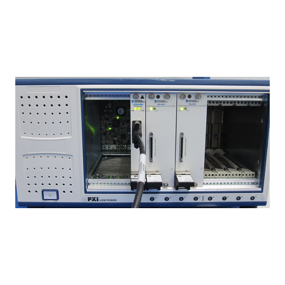
Factory installation services • Handle and rubber feet kit Chassis Components The following figures show key features of the PXIe-1088 chassis front and back panels. Figure 1. Front View of the PXIe-1088 PXIe-1088 LOW POWER 1. System Controller Expansion Slot 6. -
Page 5: Optional Equipment
PXI Slot Blocker kits are available from National Instruments for improved thermal performance when all slots are not used. Handle and Feet Kit An optional side handle and rubber feet kit is available from National Instruments to provide portability. Rack Mount Kits Rack mounting kits are available from National Instruments that can accommodate a variety of rack depths. -
Page 6: Pxie-1088 Backplane Overview
PXIe-1088 Backplane Overview Interoperability with CompactPCI The design of the PXIe-1088 provides you the flexibility to use the following devices in a single PXI Express chassis: • PXI Express compatible products • CompactPCI Express compatible 4-Link system controller products •... -
Page 7: Pxi Local Bus
1 is not routed anywhere, and the right local bus 6 from slot 9 is not routed anywhere. The backplane routes PXI Local Bus between all slots. Local bus signals may range from high-speed TTL signals to analog signals as high as 42 V. PXIe-1088 User Guide | © National Instruments | 7... -
Page 8: Pxi Trigger Bus
Trigger Bridge #1 System Reference Clock The PXIe-1088 chassis supplies PXI_CLK10, PXIe_CLK100 and PXIe_SYNC100 to every peripheral slot with an independent driver for each signal. An independent buffer (having a source impedance matched to the backplane and a skew of less than 250 ps between slots) drives PXI_CLK10 to each peripheral slot. -
Page 9: Installation And Configuration
PXIe_SYNC100 Installation and Configuration The following section describes how to prepare and operate the PXIe-1088 chassis. Before connecting the chassis to a power source, read this section and the Read Me First: Safety and Electromagnetic Compatibility document included with your kit. -
Page 10: Chassis Cooling Considerations
Unsuitable modifications may result in safety hazards. Chassis Cooling Considerations The PXIe-1088 chassis is designed to operate on a bench or in an instrument rack. You must adhere to the cooling clearances as outlined in the following section. Providing Adequate Clearance The module and power supply intake vents are located on the front, left side, and bottom of the chassis. - Page 11 To aid in thermal health monitoring for either rack or benchtop use you can monitor the chassis intake temperatures in Measurement & Automation Explorer (MAX) to ensure the temperatures do not exceed the ratings in the Operating Environment section of the PXIe-1088 Specifications.
- Page 12 Auto mode. These temperatures may be higher than ambient room temperature depending on surrounding equipment and/or blockages. Ensure ambient intake temperatures do not exceed the ratings in the Operating Environment section of the PXIe-1088 Specifications. The module ambient intake temperatures can be monitored in National Instruments Measurement &...
-
Page 13: Rack Mounting
Rack Mounting Rack mount applications require optional rack mount kits available from National Instruments. Refer to the instructions supplied with the rack mount kits to install your PXIe-1088 chassis in an instrument rack. Note You may want to remove the feet from the PXIe-1088 chassis when rack mounting. -
Page 14: Connecting The Safety Ground
Connecting the Safety Ground Caution The PXIe-1088 chassis are designed with a three-position IEC 60320 C14 inlet for the U.S. that connects the ground line to the chassis ground. For proper grounding, a suitable cordset must be used to connect this inlet to an appropriate earth safety ground. -
Page 15: Connecting To A Power Source
Figure 9. Installing a PXI Express System Controller 1. System Controller Front Panel Mounting Screws 3. Injector/Ejector Handle (4x) 4. PXI Express Chassis 2. PXI Express System Controller PXIe-1088 User Guide | © National Instruments | 15... -
Page 16: Installing Peripheral Modules
Installing Peripheral Modules This section contains general installation instructions for installing a peripheral module in a PXIe-1088 chassis. Refer to your peripheral module user manual for specific instructions and warnings. To install a module, complete the following steps: Connect the AC power source to the PXI Express chassis before installing the module. -
Page 17: Led Indicator
Description Chassis is powered off. Steady green Chassis is powered on, and operating normally. Status LED Indicates temperature is out of range, or an internal chassis fault Steady red has occurred. PXIe-1088 User Guide | © National Instruments | 17... -
Page 18: Dip Switches
On (Left) Set chassis fan mode to High. Off (Right) Set chassis inhibit mode to Default. Refer to the Inhibit Mode section for information On (Left) Set chassis inhibit mode to Manual. 18 | ni.com | PXIe-1088 User Guide... -
Page 19: Inhibit Mode
AC power is removed. Inhibit Mode Selection The chassis Inhibit Mode on the PXIe-1088 chassis is selected using a DIP switch on the backplane. Refer to the DIP Switches section for more information about the DIP switch. -
Page 20: Pxi Express System Configuration With Max
Alternatively, the fan mode on the PXIe-1088 chassis is selected using a DIP switch on the backplane. Refer to the DIP Switches section for more information about the DIP switch. Note The DIP switch must be in the Auto position for software configuration in MAX to work. - Page 21 Trigger Configuration in MAX PXI Platform Services provides an interface to route and reserve triggers so dynamic routing, through drivers such as DAQmx, avoids double-driving and potentially damaging trigger lines. PXIe-1088 User Guide | © National Instruments | 21...
- Page 22 Static reservation pre-allocates a trigger line to prevent its configuration by a user program. Dynamic reservation/routing/deallocation is on the fly within a user program based on National Instruments APIs such as NI-DAQmx. NI recommends dynamic reservations and routing are used whenever possible. If static reservations are required, static reservation of trigger lines can be implemented by the user in MAX through the Triggers tab.
- Page 23 Figure 14. Trigger Configuration in MAX PXIe-1088 User Guide | © National Instruments | 23...
-
Page 24: Using System Configuration And Initialization Files
You can configure fan behavior using software settings in MAX The PXIe-1088 supports both Auto and High fan modes for both the 38 W and 58 W cooling profiles. Refer to the Fan Mode section for more information about these modes. -
Page 25: Maintenance
For detailed information regarding initialization files, refer to the PXI Express specification at www.pxisa.org Maintenance This section describes basic maintenance procedures you can perform on the PXIe-1088 chassis. Caution Disconnect the power cable prior to servicing your PXIe-1088 chassis. -
Page 26: Worldwide Support And Services
NI trademarks. Other product and company names mentioned herein are trademarks or trade names of their respective companies. For patents covering NI products/technology, refer to the appropriate location: Help»Patents in your software, the file on your media, or the National Instruments Patent Notice at . You can find patents.txt ni.com/patents...
Need help?
Do you have a question about the PXIe-1088 and is the answer not in the manual?
Questions and answers