
Related Manuals for National Instruments NI PXI-1050


Summary of Contents for National Instruments NI PXI-1050
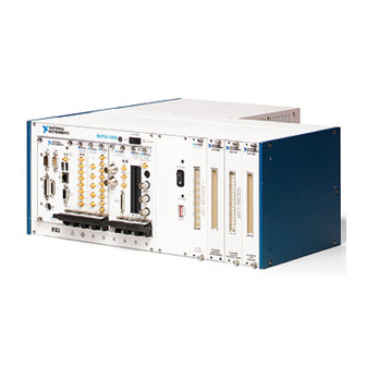
- Page 1 NI PXI-1050 User Manual Combination Chassis for PXI, CompactPCI, and SCXI Modules ™ NI PXI-1050 User Manual March 2005 371481A-01...
- Page 2 For further support information, refer to the Technical Support and Professional Services appendix. To comment on National Instruments documentation, refer to the National Instruments Web site at ni.com/info and enter the info code feedback. © 2005 National Instruments Corporation. All rights reserved.
- Page 3 Warranty The NI PXI-1050 chassis is warranted against defects in materials and workmanship for a period of one year from the date of shipment, as evidenced by receipts or other documentation. National Instruments will, at its option, repair or replace equipment that proves to be defective during the warranty period.
- Page 4 These classes are known as Class A (for use in industrial-commercial locations only) or Class B (for use in residential or commercial locations). All National Instruments (NI) products are FCC Class A products. Depending on where it is operated, this Class A product could be subject to restrictions in the FCC rules. (In Canada, the Department of Communications (DOC), of Industry Canada, regulates wireless interference in much the same way.) Digital...
-
Page 5: Table Of Contents
Chapter 1 Introduction About the PXI-1050 Chassis..................1-1 What You Need to Get Started ..................1-1 Unpacking ........................1-2 Software Programming Choices ..................1-3 National Instruments Application Software ............1-3 NI-DAQ Driver Software ................1-4 Register-Level Programming ................1-5 Optional Equipment .......................1-5 Key Features ........................1-5 Chassis Description......................1-6 SCXI Subsystem Backplane Overview .................1-9... - Page 6 Power Entry Module Fuse Replacement............3-4 SCXI Subsystem Backplane Fuse Replacement and Check ......3-4 Troubleshooting the PXI-1050 ..................3-5 Appendix A Specifications Appendix B Pinouts Appendix C Technical Support and Professional Services Glossary Index NI PXI-1050 User Manual ni.com...
-
Page 7: About This Manual
Consult these guides when you are making your connections. • PXI-1050 User Manual—Read this manual for maintenance information on the chassis and installation instructions. This manual serves as your SCXI chassis manual. © National Instruments Corporation NI PXI-1050 User Manual... -
Page 8: Conventions
SCXIbus <signal name> line (or signal). The SCXIbus descriptor may be omitted when the meaning is clear. Slot 0 Slot 0 refers to the power supply and control circuitry in the SCXI subsystem. NI PXI-1050 User Manual viii ni.com... -
Page 9: Related Documentation
The following document contains information that you might find helpful as you read this manual: • Your computer technical reference manual If you are designing your own module, the following National Instruments specification, available by request, describes the physical, electrical, and timing requirements for PXI: •... -
Page 10: Introduction
PXI-1050 chassis. About the PXI-1050 Chassis Thank you for purchasing the National Instruments PXI-1050 chassis. This chassis integrates a high-performance 8-slot PXI subsystem with a 4-slot SCXI subsystem to offer a complete solution for signal conditioning applications. -
Page 11: Unpacking
Inspect the inner chassis for any possible damage, debris, or detached components. If damage appears to have been caused in shipment, file a claim with the carrier. Retain the packing material for possible inspection and/or reshipment. NI PXI-1050 User Manual ni.com... -
Page 12: Software Programming Choices
Introduction Software Programming Choices You have several options to choose from when programming your National Instruments DAQ and SCXI hardware. You can use National Instruments application software, NI-DAQ, or register-level programming. National Instruments Application Software ComponentWorks contains tools for data acquisition and instrument control built on NI-DAQ driver software. -
Page 13: Ni-Daq Driver Software
NI-DAQ maintains a consistent software interface among its different versions so that you can change platforms with minimal modifications to your code. Whether you are using conventional programming languages or National Instruments application software, your application uses the NI-DAQ driver software, as illustrated in Figure 1-1. ComponentWorks,... -
Page 14: Register-Level Programming
Optional Equipment National Instruments offers a variety of products to use with your PXI-1050 chassis, including cables and other accessories, as follows: •... -
Page 15: Chassis Description
When lit, indicates that the PXI subsystem is powered on PXI power switch Turns the PXI subsystem on and off Front-threaded strips Secure modules in the chassis and attach front panels SCXI indicator light When lit, indicates that the SCXI subsystem is powered on NI PXI-1050 User Manual ni.com... - Page 16 PXI System Controller slot Holds PXI system controller PXI controller expansion slots Provide space for large controllers Figure 1-3 shows the chassis rear view items that are then described in Table 1-3. © National Instruments Corporation NI PXI-1050 User Manual...
- Page 17 Protects both you and the PXI subsystem in case of a PXI subsystem fault Fans and filters Cool the chassis; prevent dirt from contaminating the chassis circuitry Backplane fuses Protect the SCXI subsystem power supply from module shorts NI PXI-1050 User Manual ni.com...
-
Page 18: Scxi Subsystem Backplane Overview
P2 connector and are found only on the signals that are reserved or not used in the CompactPCI 64-bit specification. Therefore, all modules that meet the CompactPCI 64-bit specification requirements will function in the PXI-1050. © National Instruments Corporation NI PXI-1050 User Manual... -
Page 19: System Controller Slot
This software uses the configuration information specific to each peripheral module to evaluate compatibility. This method is a flexible way to define local bus functionality that is not limited by keying hardware. NI PXI-1050 User Manual 1-10 ni.com... -
Page 20: Scxi Connection
Modules can pass triggers to one another, allowing precisely timed responses to asynchronous external events the system is monitoring or controlling. © National Instruments Corporation 1-11 NI PXI-1050 User Manual... -
Page 21: System Reference Clock
PXI_CLK10_IN pin on the P2 connector of the Star Trigger slot. (Refer to Table B-4, P2 (J2) Connector Pinout for the Star Trigger Slot.) Sourcing an external clock on this pin automatically disables the backplane 10 MHz source. NI PXI-1050 User Manual 1-12 ni.com... -
Page 22: Installation And Configuration
Install your chassis for easy access to the rear panel. This simplifies the air filter replacement. Rack-mount applications require the optional rack-mount kit available from National Instruments. Refer to the rack-mount kit documentation to install your PXI-1050 in an instrument rack. Chassis Configuration Chassis configuration involves selecting an SCXI subsystem address, line voltage, and fuse value, described briefly in the following sections. -
Page 23: Line Voltage Selection And Fuse Values
SLO-BLO type, which has a current rating relative to the operating voltage. Table 2-1 shows the proper voltage selection and fuse ratings for different geographical regions. Caution For continued protection against fire, replace fuses only with fuses of the same type and rating. NI PXI-1050 User Manual ni.com... - Page 24 100 VAC 3/4 A Europe 240 VAC 1/4 A Switzerland 220 VAC 1/4 A Table 2-2 shows the manufacturer part numbers National Instruments uses for these fuses. Table 2-2. PXI-1050 Fuse Part Numbers Fuse Rating Manufacturer Part Number 1/4 A Littelfuse 218.250...
-
Page 25: Pxi-1050 Chassis Installation
Turn on the chassis power switches. PXI Module Installation Caution Turn off the PXI subsystem power using the power switch shown in Figure 1-2, Front View of the PXI-1050 Chassis, before installing CompactPCI or PXI modules. NI PXI-1050 User Manual ni.com... - Page 26 I - 1 0 5 0 1 PXI-1050 Chassis 3 PXI Module 5 Injector/Ejector Rail 2 System Controller 4 Injector/Ejector Handle Figure 2-2. Installing PXI or CompactPCI Modules (PXI Module Shown) © National Instruments Corporation NI PXI-1050 User Manual...
-
Page 27: Pxi Filler Panel Installation
SCXI chassis using the thumbscrews on the module front panel. Install any necessary cabling. The installation is complete. Refer to your SCXI module documentation for specific instructions pertaining to the module, especially module cabling. NI PXI-1050 User Manual ni.com... -
Page 28: Scxi Filler Panel Installation
ASCII text. The system integrator can read the file, and .ini configuration utilities and device drivers can also use this file. The PXI-1050 chassis initialization file, , is included on the chassis .ini media for your PXI-1050. © National Instruments Corporation NI PXI-1050 User Manual... -
Page 29: Maintenance
Always power off the chassis and disconnect the power cable before cleaning or servicing the chassis. Interior Cleaning Use a dry, low-velocity stream of air to clean the chassis interior. Use a soft-bristle brush for cleaning around components. © National Instruments Corporation NI PXI-1050 User Manual... -
Page 30: Exterior Cleaning
To remove the fan filter, remove the four screws that secure the fan and filter to the rear of the chassis. When removing the last screw, be careful to hold the fan to prevent breaking the fan wires. NI PXI-1050 User Manual ni.com... -
Page 31: Resetting The Ac Main Circuit Breaker
Refer to Appendix A, Specifications, for power requirements. The over-current condition that caused the circuit breaker to trip may be due to a faulty CompactPCI or PXI module. Refer to your module documentation to troubleshoot your modules. © National Instruments Corporation NI PXI-1050 User Manual... -
Page 32: Scxi Subsystem Fuse Replacement
Make sure to power off the chassis and remove the power cable. The fuse marked with a copper + on the backplane is for the positive analog supply, and the fuse marked with a copper – is for the negative NI PXI-1050 User Manual ni.com... -
Page 33: Troubleshooting The Pxi-1050
Set the PXI power switch to the On switched on. position. Circuit breaker is tripped. Reset the circuit breaker. Refer to the Resetting the AC Main Circuit Breaker section of this chapter. Power supply has failed. Contact National Instruments. © National Instruments Corporation NI PXI-1050 User Manual... -
Page 34: Specifications
.25 A Slow 240 VAC 216–264 .25 A Slow Line regulation 3.3 V..........<±0.2% 5 V........... <±0.1% ±12 V ..........<±0.1% Efficiency ..........70% typical The operating range is guaranteed by design. © National Instruments Corporation NI PXI-1050 User Manual... - Page 35 Maximum ripple and noise (20 MHz bandwidth) Voltage Maximum Ripple and Noise +3.3 V 50 mV +12 V 120 mV +5 V 50 mV –12 V 120 mV Over-current protection ......All outputs protected from short circuit and overload with automatic recovery NI PXI-1050 User Manual ni.com...
- Page 36 +5 V output ..........50 mA PXI Subsystem Cooling Per slot cooling capacity ......Slot cooling capacity in worst-case slot is 25 W Module cooling system ......Forced air circulation (positive pressurization) through two fans © National Instruments Corporation NI PXI-1050 User Manual...
- Page 37 Relative humidity range......10 to 90%, noncondensing (Tested in accordance with IEC-60068-2-56.) Storage Environment Ambient temperature range ....–20 to 70 °C (Tested in accordance with IEC-60068-2-1 and IEC-60068-2-2.) Relative humidity range......5 to 95%, noncondensing (Tested in accordance with IEC-60068-2-56.) NI PXI-1050 User Manual ni.com...
- Page 38 Emissions ..........EN 55011 Class A at 10 m FCC Part 15A above 1 GHz Immunity ..........EN 61326:1997 + A2:2001, Table 1 EMC/EMI..........CE, C-Tick, and FCC Part 15 (Class A) Compliant DC input exempt from emissions requirements. © National Instruments Corporation NI PXI-1050 User Manual...
- Page 39 Accepts both PXI and CompactPCI (PICMG 2.0 R2.1) 3U modules. Backplane bare-board material ....UL 94 V-0 recognized (File No. E 116551) Backplane connectors ......Conform to IEC 917 and IEC 1076-4-101, and are UL 94 V-0 rated NI PXI-1050 User Manual ni.com...
- Page 40 1 ps RMS in 10 Hz to 1 MHz range Mechanical Overall dimensions ........ Refer to Figure A-1 through Figure A-3 for the physical dimensions of the PXI-1050 chassis Weight............ 13 kg (29 lb) © National Instruments Corporation NI PXI-1050 User Manual...
- Page 41 1 PXI Subsystem (8 slots) 2 SCXI Subsystem (4 slots) Figure A-1. PXI-1050 Dimensions (Front View Shown) 6.970 in. [177.04 mm] 9.825 in. [249.1 mm] 17.250 in. [438.56 mm] Figure A-2. PXI-1050 Dimensions (Rear View Shown) NI PXI-1050 User Manual ni.com...
- Page 42 [438.15 mm] 9.825 in. [249.56 mm] 16.241 in. [412.52 mm] 16.380 in. 1.212 in. [416.04 mm] [30.78 mm] 17.600 in. [447.07 mm] 9.570 in. [243.1 mm] Figure A-3. PXI-1050 Dimensions (Top View Shown) © National Instruments Corporation NI PXI-1050 User Manual...
- Page 43 PXI signals are shown in bold. Note For more detailed information, refer to the PXI Hardware Specification, Revision 2.1. Contact the PXI Systems Alliance for a copy of the specification or visit www.pxisa.org © National Instruments Corporation NI PXI-1050 User Manual...
- Page 44 AD[21] 3.3V AD[20] AD[19] C/BE[3]# AD[23] AD[22] AD[26] V(I/O) AD[25] AD[24] AD[30] AD[29] AD[28] AD[27] REQ0# 3.3V CLK0 AD[31] BRSVP1A5 BRSVP1B5 RST# GNT0# IPMB_PWR HEALTHY V(I/O) INTP INTS INTA# INTB# INTC# INTD# –12V TRST# +12V NI PXI-1050 User Manual ni.com...
- Page 45 AD[55] AD[54] AD[53] AD[59] V(I/O) AD[58] AD[57] AD[63] AD[62] AD[61] AD[60] C/BE[5]# V(I/O) C/BE[4]# PAR64 V(I/O) PXI_BRSVB4 C/BE[7]# C/BE[6]# CLK4 GNT3# REQ4# GNT4# CLK2 CLK3 SYSEN# GNT2# REQ3# CLK1 REQ1# GNT1# REQ2# © National Instruments Corporation NI PXI-1050 User Manual...
- Page 46 AD[21] 3.3V AD[20] AD[19] C/BE[3]# IDSEL AD[23] AD[22] AD[26] V(I/O) AD[25] AD[24] AD[30] AD[29] AD[28] AD[27] REQ# 3.3V AD[31] BRSVP1A5 BRSVP1B5 RST# GNT# IPMB_PWR HEALTHY V(I/O) INTP INTS INTA# INTB# INTC# INTD# –12V TRST# +12V NI PXI-1050 User Manual ni.com...
- Page 47 AD[56] AD[55] AD[54] AD[53] AD[59] V(I/O) AD[58] AD[57] AD[63] AD[62] AD[61] AD[60] C/BE[5]# V(I/O) C/BE[4]# PAR64 V(I/O) PXI_BRSVB4 C/BE[7]# C/BE[6]# PXI_LBR7 PXI_LBR8 PXI_LBR9 PXI_LBR10 PXI_LBR11 PXI_LBR12 PXI_STAR7 PXI_STAR8 PXI_STAR9 PXI_STAR10 PXI_STAR11 PXI_STAR12 © National Instruments Corporation NI PXI-1050 User Manual...
- Page 48 AD[21] 3.3V AD[20] AD[19] C/BE[3]# IDSEL AD[23] AD[22] AD[26] V(I/O) AD[25] AD[24] AD[30] AD[29] AD[28] AD[27] REQ# 3.3V AD[31] BRSVP1A5 BRSVP1B5 RST# GNT# IPMB_PWR HEALTHY V(I/O) INTP INTS INTA# INTB# INTC# INTD# –12V TRST# +12V NI PXI-1050 User Manual ni.com...
- Page 49 AD[56] AD[55] AD[54] AD[53] AD[59] V(I/O) AD[58] AD[57] AD[63] AD[62] AD[61] AD[60] C/BE[5]# V(I/O) C/BE[4]# PAR64 V(I/O) PXI_BRSVB4 C/BE[7]# C/BE[6]# PXI_LBR7 PXI_LBR8 PXI_LBR9 PXI_LBR10 PXI_LBR11 PXI_LBR12 PXI_LBL7 PXI_LBL8 PXI_LBL9 PXI_LBL10 PXI_LBL11 PXI_LBL12 © National Instruments Corporation NI PXI-1050 User Manual...
- Page 50 Technical Support and Professional Services Visit the following sections of the National Instruments Web site at for technical support and professional services: ni.com • Support—Online technical support resources at ni.com/support include the following: – Self-Help Resources—For answers and solutions, visit the...
- Page 51 You also can visit the Worldwide Offices section of to access the branch ni.com/niglobal office Web sites, which provide up-to-date contact information, support phone numbers, email addresses, and current events. NI PXI-1050 User Manual ni.com...
- Page 52 An assembly, typically a printed circuit board, with connectors and signal paths that bus the connector pins bandwidth The range of frequencies present in a signal, or the range of frequencies to which a measuring device can respond © National Instruments Corporation NI PXI-1050 User Manual...
- Page 53 Electromagnetic Compatibility Federal Communications Commission 1. Grams 2. A measure of acceleration equal to 9.8 m/s Ground signal A measure of random vibration; the root mean square of acceleration levels in a random vibration test profile NI PXI-1050 User Manual ni.com...
- Page 54 A group of signals that connect two peripheral slots Meters MTBF Mean time between failure NEMA National Electrical Manufacturers Association over-current condition When the lead on a power supply draws more current than what the power supply is rated for © National Instruments Corporation NI PXI-1050 User Manual...
- Page 55 Seconds SCXI SCXI stands for Signal Conditioning eXtensions for Instrumentation and is a National Instruments product line designed to perform front-end signal conditioning for National Instruments plug-in DAQ devices. SCXI subsystem The PXI-1050 chassis section that uses SCXI modules...
- Page 56 Any event that causes or starts some form of data capture Transistor-transistor logic Underwriter’s Laboratories Volts Volts alternating current voltage selection Configures the chassis for the AC line voltage wheel Watts © National Instruments Corporation NI PXI-1050 User Manual...
- Page 57 ComponentWorks software, 1-3 line voltage-selection and fuse values, 2-2 configuration fuse part numbers (table), 2-3 See also installation voltage selection and fuse ratings by line voltage-selection and fuse values, 2-2 region (table), 2-3 © National Instruments Corporation NI PXI-1050 User Manual...
- Page 58 (NI resources), C-1 National Instruments key features of the PXI-1050 chassis, 1-5 application software, 1-3 KnowledgeBase, C-1 support and services, C-1 NI-DAQ driver software overview, 1-4 relationship with programming environment and hardware (figure), 1-4 NI PXI-1050 User Manual ni.com...
- Page 59 1-12 installation register-level programming, 1-5 injector/ejector handle position related documentation, ix (figure), 2-6 requirements for getting started, 1-1 procedure, 2-4 resetting AC main circuit breaker, 3-3 PXI or CompactPCI modules (figure), 2-5 © National Instruments Corporation NI PXI-1050 User Manual...
- Page 60 A-5 mechanical, A-7 safety, A-5 specifications, PXI-1050 Web resources, C-1 environmental, A-4 Star Trigger slot description, 1-10 figure, 1-6 P1 (J1) connector pinouts (table), B-4 P2 (J2) connector pinouts (table), B-5 support, technical, C-1 NI PXI-1050 User Manual ni.com...
Need help?
Do you have a question about the NI PXI-1050 and is the answer not in the manual?
Questions and answers