National Instruments SCXI-1000 User Manual
Hide thumbs
Also See for SCXI-1000:
- Getting started (158 pages) ,
- Quick start manual (143 pages) ,
- User manual (73 pages)
Table of Contents
Advertisement
Advertisement
Table of Contents

Related Manuals for National Instruments SCXI-1000


Summary of Contents for National Instruments SCXI-1000
- Page 1 SCXI SCXI Chassis User Manual SCXI Chassis User Manual April 2006 374423L-01...
- Page 2 Thailand 662 278 6777, United Kingdom 44 0 1635 523545 For further support information, refer to the Signal Conditioning Technical Support Information document. To comment on National Instruments documentation, refer to the National Instruments Web site at ni.com/info and enter the info code feedback.
- Page 3 The reader should consult National Instruments if errors are suspected. In no event shall National Instruments be liable for any damages arising out of or related to this document or the information contained in it.
- Page 4 Refers to both NI-DAQmx and Traditional NI-DAQ (Legacy) unless otherwise noted. SCXI chassis Refers to the SCXI-1000, SCXI-1000DC, and SCXI-1001. When information pertains to only one chassis, that chassis is named explicitly; for example, the SCXI-1001 has 12 module slots.
-
Page 5: Table Of Contents
Configuring the SCXI Chassis..................2-8 Selecting Chassis Addresses................2-8 SCXI-1000/1001 ................2-8 SCXI-1000DC...................2-9 Selecting Voltage and Replacing the Fuse for the SCXI-1000 and SCXI-1001 .....................2-11 Selecting the Voltage ................2-13 Replacing the Power Entry Module Fuse .........2-14 Replacing and Checking Backplane Fuses on the SCXI-1000 and SCXI-1001 ................2-14... - Page 6 SCXI Chassis Front View Items ............2-1 Table 2-2. SCXI-1000/1001 Chassis Rear View Items ......... 2-4 Table 2-3. SCXI-1000DC Chassis Rear View Items ..........2-6 Table 2-4. SCXI-1000/1001 Voltage Selection and Fuse Ratings by Region ..2-12 SCXI Chassis User Manual ni.com...
-
Page 7: About The Scxi Chassis
The SCXI chassis supply power to and contain control circuitry for the SCXI series of modules. The SCXI-1000 and SCXI-1000DC hold up to four modules. The SCXI-1001 holds up to 12 modules. This chapter describes the SCXI chassis, lists what you need to get started, and describes the optional software and equipment. -
Page 8: Software Programming Choices
Chapter 1 Introduction – One of the following, depending on your application: • Power cord (120, 220, or 240 VAC) • SCXI-1382 battery pack (SCXI-1000DC only) • SCXI-1383 (VDC) power supply (SCXI-1000DC only) – A computer ❑ Software – NI-DAQ –... -
Page 9: National Instruments Ade Software
Visual Basic, is a development suite that allows you to design test and measurement applications. For Visual Basic developers, Measurement Studio features a set of ActiveX controls for using National Instruments DAQ hardware. These ActiveX controls provide a high-level programming interface for building virtual instruments (VIs). -
Page 10: National Instruments Documentation
Chapter 1 Introduction National Instruments Documentation The SCXI Chassis User Manual is one piece of the documentation set for the data acquisition and SCXI system. You could have any of several types of documents, depending on the hardware and software in the system. Use the documents you have as follows: •... -
Page 11: Optional Equipment
BNC connectors, or thermocouple plugs are available to connect signals to the modules. Refer to the latest NI catalog and for a complete listing ni.com/catalog of sensors and I/O types supported in SCXI. © National Instruments Corporation SCXI Chassis User Manual... -
Page 12: Configuring And Installing The Scxi Chassis
Reinitializes Slot 0 and all modules to their power-on state when pressed Slot 0/power supply Contains the power supply and control circuitry for the chassis Address DIP switches Determine the chassis address—SCXI-1000 and SCXI-1001 Address selection Determine the chassis address—SCXI-1000DC only jumpers (located behind the front panel) -
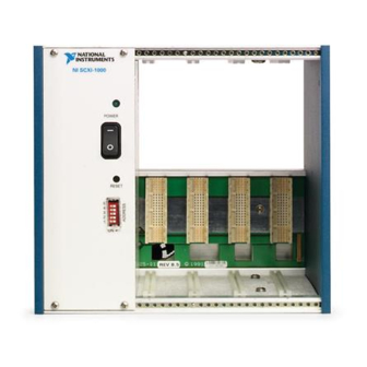
Page 13: Figure 2-1. Scxi-1000 Front View Diagram
(early revisions only) 3 Power Switch 7 Module Guides 4 Indicator Light 8 Front Threaded Strips 5 Front Panel Screws 9 Backplane (flathead on some revisions) 10 Slot 0/Power Supply Figure 2-1. SCXI-1000 Front View Diagram SCXI Chassis User Manual ni.com... -
Page 14: Figure 2-2. Scxi-1000Dc Front View Diagram
7 Module Guides 3 Power Switch 8 Front Threaded Strips 4 Indicator Light 9 Backplane 5 Front Panel Screws 10 Slot 0/Power Supply (flathead on some revisions) Figure 2-2. SCXI-1000DC Front View Diagram © National Instruments Corporation SCXI Chassis User Manual... -
Page 15: Figure 2-3. Scxi-1001 Front View Diagram
10 Slot 0/Power Supply Figure 2-3. SCXI-1001 Front View Diagram Tables 2-2 and 2-3 describe the rear view items shown in Figures 2-4, 2-5, and 2-6. Table 2-2. SCXI-1000/1001 Chassis Rear View Items Item Description Power entry module IEC receptacle for power input, voltage selection board, and fuse... -
Page 16: Figure 2-4. Scxi-1000 Rear View Diagram
Chapter 2 Configuring and Installing the SCXI Chassis Table 2-2. SCXI-1000/1001 Chassis Rear View Items (Continued) Item Description Backplane fuses Protect the power supply from shorts on modules Rear connector space For module space, connector mounting brackets, or adapters Rear threaded strips... -
Page 17: Figure 2-5. Scxi-1001 Rear View Diagram
Chapter 2 Configuring and Installing the SCXI Chassis 120Vac 1 Fans and Filters 6 Voltage Tumbler 2 Fan Screws (each fan) 7 Power Entry Module 3 Rear Threaded Strips 8 Fuse (concealed) 4 Rear Connector Space 9 Backplane Fuses (behind fan) 5 Rear Panel Screws (flathead on some revisions) Figure 2-5. -
Page 18: Chassis Uses
In parallel mode, you need a separate E/M Series DAQ device for each module to send each of its output channels directly to a separate AI channel of the E/M Series DAQ device connected to the module. © National Instruments Corporation SCXI Chassis User Manual... -
Page 19: Configuring The Scxi Chassis
0 and the switch setting for chassis address 19. SCXI-1000 chassis through revision D do not have address jumpers or switches Notes and respond to any address, but you cannot use them in multichassis systems. Revision E chassis use jumpers on Slot 0 for chassis addressing. -
Page 20: Scxi-1000Dc
SCXI-1000DC chassis through revision C do not have address jumpers or switches and respond to any address, but you cannot use them in multichassis systems. Revision D and later chassis use jumpers on Slot 0 for chassis addressing. © National Instruments Corporation SCXI Chassis User Manual... -
Page 21: Figure 2-8. Scxi-1000Dc Chassis Address Jumper Settings
Chapter 2 Configuring and Installing the SCXI Chassis Chassis Address 0 Chassis Address 19 Factory Setting Example Setting Figure 2-8. SCXI-1000DC Chassis Address Jumper Settings Changing the Chassis Address While referring to Figures 2-2 and 2-6, complete the following steps to change the chassis address of the SCXI-1000DC: Power off the chassis and remove the power cord from the power entry module. -
Page 22: Selecting Voltage And Replacing The Fuse For The Scxi-1000 And Scxi-1001
Chapter 2 Configuring and Installing the SCXI Chassis Selecting Voltage and Replacing the Fuse for the SCXI-1000 and SCXI-1001 If you ordered the chassis with the appropriate part number (the -0x extension of the kit part number corresponds to your geographical region), the voltage tumbler and fuse are correct for operation in your geographical region. -
Page 23: Table 2-4. Scxi-1000/1001 Voltage Selection And Fuse Ratings By Region
Chapter 2 Configuring and Installing the SCXI Chassis Table 2-4. SCXI-1000/1001 Voltage Selection and Fuse Ratings by Region SCXI Main Backplane Chassis Power Fuse Main Power Fuse Backplane Type Region/Voltage Quantity Fuse Type Quantity Fuse Type SCXI-1000 100 V Japan T0.75A 250V... -
Page 24: Selecting The Voltage
Chapter 2 Configuring and Installing the SCXI Chassis Table 2-4. SCXI-1000/1001 Voltage Selection and Fuse Ratings by Region (Continued) SCXI Main Backplane Chassis Power Fuse Main Power Fuse Backplane Type Region/Voltage Quantity Fuse Type Quantity Fuse Type SCXI-1001 100 V Japan T3.0A 250 V... -
Page 25: Replacing The Power Entry Module Fuse
SCXI-1000 and SCXI-1001 In addition to the power entry module fuse, the analog supply lines on the backplane are fused at 1.5 A on the SCXI-1000 chassis and at 4 A on the SCXI-1001 chassis. If you are making your own modules, fuse the module at 250 mA to avoid blowing the backplane fuses. -
Page 26: Replacing The Fuses On The Scxi-1000Dc
Remove the fuse. Install the new fuse. Push the fuse holder back into the housing and screw it clockwise until it is secure. Reinsert the power cord. © National Instruments Corporation 2-15 SCXI Chassis User Manual... -
Page 27: Replacing And Checking Backplane Fuses
Chapter 2 Configuring and Installing the SCXI Chassis Replacing and Checking Backplane Fuses In addition to the power entry and the +5 V supply fuses, the analog supply lines on the backplane are fused at 1.5 A on the SCXI-1000DC chassis. If you design a special/prototype module, use the SCXI-1181 module and fuse the module at 250 mA to avoid blowing the analog backplane and +5 V supply fuses. -
Page 28: Installing The Scxi Chassis
Installing the SCXI Chassis These sections provide information about installing the SCXI chassis. Installing the SCXI-1000 and SCXI-1001 Chassis Complete the following steps to install the SCXI-1000 and SCXI-1001 chassis: If necessary, change the chassis address of the box by following the... -
Page 29: Installing Filler Panels
Chapter 2 Configuring and Installing the SCXI Chassis Make sure the voltage of the power source is between 9.5 and 16 VDC. Insert the power plug into the header J1. Revision A SCXI-1000DC chassis have screw terminals on the rear panel to Caution connect the power source. -
Page 30: Installing Rear Panels
Replace the fan filter by aligning the fan and filter with the fan holes, making sure that the label side of the fan is face down. Reinstall the four screws and make sure the assembly is secure. © National Instruments Corporation 2-19 SCXI Chassis User Manual... - Page 31 +5 V Tolerance limits include +4.75 to +5.25 V +4.75 to +5.25 V peaks Ripple (peak-to-peak) 50 mV 50 mV Max load 250 mA 600 mA Power dissipation ........7 W per slot © National Instruments Corporation SCXI Chassis User Manual...
- Page 32 SCXI-1000DC ........3.3 kg (7 lb, 5 oz) SCXI-1001..........6.8 kg (14 lb, 14 oz) Refer to Figures A-1 and A-2 for the physical dimensions of the four-slot chassis (SCXI-1000 and SCXI-1000DC) and the 12-slot chassis (SCXI-1001). SCXI Chassis User Manual ni.com...
- Page 33 Appendix A Specifications © National Instruments Corporation SCXI Chassis User Manual...
- Page 34 Appendix A Specifications SCXI Chassis User Manual ni.com...
- Page 35 FCC Part 15A above 1 GHz Immunity ..........EN 61326:1997 + A2:2001, Table 1 EMC/EMI..........CE, C-Tick, and FCC Part 15 (Class A) Compliant For EMC compliance, operate this device with shielded cabling. Note © National Instruments Corporation SCXI Chassis User Manual...
- Page 36 Appendix A Specifications CE Compliance The chassis meet the essential requirements of applicable European Directives, as amended for CE marking, as follows: Low-Voltage Directive (safety)....73/23/EEC Electromagnetic Compatibility Directive (EMC) ........89/336/EEC Note Refer to the Declaration of Conformity (DoC) for this product for any additional regulatory compliance information.
-
Page 37: Common Questions
What is causing this problem? The SCXI chassis has backplane fuses. One or both of these fuses could be blown. Refer to the Replacing and Checking Backplane Fuses on the SCXI-1000 and SCXI-1001 section of Chapter 2, Configuring and Installing the SCXI Chassis, for fuse replacement information. -
Page 38: Glossary
Numbers/Symbols ° degrees – negative of, or minus Ω ohms ± plus or minus positive of, or plus percent +5 V (signal) +5 VDC source signal amperes analog-to-digital alternating current Celsius © National Instruments Corporation SCXI Chassis User Manual... - Page 39 Glossary digital-to-analog data acquisition—(1) collecting and measuring electrical signals from sensors, transducers, and test probes or fixtures and processing the measurement data using a computer; (2) collecting and measuring the same kinds of electrical signals with A/D and/or DIO boards plugged into a computer, and possibly generating control signals with D/A and/or DIO boards in the same computer fuse...
- Page 40 Glossary pounds ounces seconds SCXI Signal Conditioning eXtensions for Instrumentation volts volts, alternating current volts, direct current watts © National Instruments Corporation SCXI Chassis User Manual...
- Page 41 2-8 +5 VDC fuse replacement, jumper settings SCXI-1000DC, 2-15 SCXI-1000 and SCXI-1001 voltage selection for SCXI-1000 and (figure), 2-9 SCXI-1001 SCXI-1000DC (figure), 2-10 procedure, 2-13 jumperless chassis (note), 2-8 voltage selection and fuse ratings by...
- Page 42 Index fuse replacement overview, 1-1 backplane fuse replacement and check SCXI chassis descriptions procedure front view diagrams SCXI-1000 and SCXI-1001, 2-14 SCXI-1000, 2-2 SCXI-1000DC, 2-16 SCXI-1000DC, 2-3 fuse ratings by region (table) SCXI-1001, 2-4 SCXI-1000 and SCXI-1001, 2-12 front view items (table), 2-1...
- Page 43 Index fuse replacement safety, A-5 +5 VDC fuse replacement, 2-15 source power requirements backplane fuse replacement and SCXI-1000 and 1001, A-2 check procedure, 2-16 SCXI-1000DC, A-2 power entry fuse and +5 VDC, 2-15 weight, A-2 installation, 2-17 physical dimensions (figure), A-4...
Need help?
Do you have a question about the SCXI-1000 and is the answer not in the manual?
Questions and answers