Table of Contents
Advertisement
USER GUIDE
PXIe-1092
This document describes the features of the PXIe-1092 chassis and contains information about
configuring the chassis, installing the modules, and operating the chassis.
Contents
Related Documentation ............................................................................................................2
Getting Started.......................................................................................................................... 2
Unpacking......................................................................................................................... 2
What You Need to Get Started..........................................................................................2
Key Features..................................................................................................................... 3
Chassis Components......................................................................................................... 4
Optional Equipment.......................................................................................................... 5
PXIe-1092 Backplane Overview.............................................................................................. 6
Interoperability with CompactPCI.................................................................................... 6
System Controller Slot...................................................................................................... 6
Hybrid Peripheral Slots..................................................................................................... 7
System Timing Slot...........................................................................................................8
Peripheral Expansion Slot................................................................................................. 9
PXI Local Bus................................................................................................................. 10
PXI Trigger Bus.............................................................................................................. 11
System Reference Clock................................................................................................. 11
Installation and Configuration................................................................................................ 12
Safety Information.......................................................................................................... 13
Chassis Cooling Considerations......................................................................................13
Rack Mounting................................................................................................................16
Connecting the Safety Ground........................................................................................ 17
Connecting to a Power Source........................................................................................ 17
Installing a System Controller.........................................................................................18
Installing Peripheral Modules......................................................................................... 19
Installing Peripheral Modules in the Peripheral Expansion Slot.................................... 20
LED Indicators................................................................................................................ 22
DIP Switches...................................................................................................................22
Inhibit Mode....................................................................................................................23
Fan Mode........................................................................................................................ 24
PXI Express System Configuration with MAX.............................................................. 25
Using System Configuration and Initialization Files...................................................... 28
Maintenance............................................................................................................................ 28
Service Interval............................................................................................................... 29
Preparation...................................................................................................................... 29
Advertisement
Table of Contents

Related Manuals for National Instruments PXIe-1092


Summary of Contents for National Instruments PXIe-1092
-
Page 1: Table Of Contents
USER GUIDE PXIe-1092 This document describes the features of the PXIe-1092 chassis and contains information about configuring the chassis, installing the modules, and operating the chassis. Contents Related Documentation ......................2 Getting Started.......................... 2 Unpacking......................... 2 What You Need to Get Started..................2 Key Features........................ -
Page 2: Related Documentation
Retain the packing material for possible inspection and/or reshipment. What You Need to Get Started The PXIe-1092 chassis kit contains the following items: • PXIe-1092 chassis •... -
Page 3: Key Features
The chassis’ modular design ensures a high level of maintainability, resulting in a very low mean time to repair (MTTR). The PXIe-1092 chassis fully complies with the PXI-5 PXI Express Hardware Specification, offering advanced timing and synchronization features. -
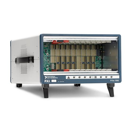
Page 4: Chassis Components
EMC filler panels • Slot blockers for improved cooling performance • Factory installation services • Replacement fan kit Chassis Components The following figures show key features of the PXIe-1092 chassis front and back panels. 4 | ni.com | PXIe-1092 User Guide... -
Page 5: Optional Equipment
1. Rear Panel Power Supply LED 4. Chassis Protective Earth Terminal 2. Power Supply 5. Fan Module 3. Universal AC Input Optional Equipment Contact National Instruments to order the following options for the PXIe-1092 chassis. PXIe-1092 User Guide | © National Instruments | 5... -
Page 6: Pxie-1092 Backplane Overview
Rack mounting kits are available from National Instruments that can accommodate a variety of rack depths. PXIe-1092 Backplane Overview Interoperability with CompactPCI The design of the PXIe-1092 provides you the flexibility to use the following devices in a single PXI Express chassis: • PXI Express compatible products •... -
Page 7: Hybrid Peripheral Slots
The hybrid peripheral slots provide full PXI Express functionality and 32-bit PXI functionality except for PXI Local Bus. The hybrid peripheral slot only connects to PXI Local Bus 6 left and right. PXIe-1092 User Guide | © National Instruments | 7... -
Page 8: System Timing Slot
Figure 3. PXIe-1092 PCI Express Backplane Diagram Primary PCIe Switch Port 12 Port 13 Port 14 Station 1 Gen3 x16 Virtual Switch 1 Virtual Switch 0 32-bit, 33 MHz PCI 32-bit, 33 MHz PCI Gen3 x8 Station 1 Port 4 Port 5... -
Page 9: Peripheral Expansion Slot
A single-slot module installed in the peripheral expansion slot will not be functional. Note For connector pinouts for the chassis backplane, refer to the PXI-5 PXI Express Hardware Specification, Revision 2.0. PXIe-1092 User Guide | © National Instruments | 9... -
Page 10: Pxi Local Bus
The backplane routes PXI Local Bus 6 between all slots. The left local bus 6 from slot 1 is not routed anywhere, and the right local bus 6 from slot 9 is not routed anywhere. 10 | ni.com | PXIe-1092 User Guide... -
Page 11: Pxi Trigger Bus
Bridge #1 Bridge #2 System Reference Clock The PXIe-1092 chassis supplies PXI_CLK10, PXIe_CLK100 and PXIe_SYNC100 to every peripheral slot with an independent driver for each signal. An independent buffer (having a source impedance matched to the backplane and a skew of less than 250 ps between slots) drives PXI_CLK10 to each peripheral slot. -
Page 12: Installation And Configuration
PXIe_SYNC100 signals to this external clock and distributes these signals to the slots. Refer to the PXIe-1092 Specifications section for the specification information for an external clock provided on the PXI_CLK10_IN pin of the System Timing Slot or rear panel SMA. -
Page 13: Safety Information
Unsuitable modifications may result in safety hazards. Chassis Cooling Considerations The PXIe-1092 chassis is designed to operate on a bench or in an instrument rack. You must adhere to the cooling clearances as outlined in the following section. Providing Adequate Clearance The module and power supply exhaust vents for the PXIe-1092 are on the top of the chassis. - Page 14 To aid in thermal health monitoring for either rack or benchtop use you can monitor the chassis intake temperatures in Measurement & Automation Explorer (MAX) to ensure the temperatures do not exceed the ratings in the Operating Environment section of the PXIe-1092 Specifications.
- Page 15 Auto mode. These temperatures may be higher than ambient room temperature depending on surrounding equipment and/or blockages. Ensure ambient intake temperatures do not exceed the ratings in the Operating Environment section of the PXIe-1092 PXIe-1092 User Guide | © National Instruments | 15...
-
Page 16: Rack Mounting
Rack Mounting Rack mount applications require optional rack mount kits available from National Instruments. Refer to the instructions supplied with the rack mount kits to install your PXIe-1092 chassis in an instrument rack. Note You must remove the feet and carry handle from the PXIe-1092 chassis when rack mounting. -
Page 17: Connecting The Safety Ground
Connecting the Safety Ground Caution The PXIe-1092 chassis are designed with a three-position IEC 60320 C14 inlet for the U.S. that connects the ground line to the chassis ground. For proper grounding, a suitable cordset must be used to connect this inlet to an appropriate earth safety ground. -
Page 18: Installing A System Controller
PCB into the front of the card guides (top and bottom). Slide the system controller to the rear of the chassis, making sure the injector/ejector handle is pushed down as shown in the following figure. 18 | ni.com | PXIe-1092 User Guide... -
Page 19: Installing Peripheral Modules
Installing Peripheral Modules Caution The PXIe-1092 chassis has been designed to accept a variety of peripheral module types in different slots. To prevent damage to the chassis, ensure that the peripheral module is being installed into a slot designed to accept it. -
Page 20: Installing Peripheral Modules In The Peripheral Expansion Slot
The peripheral expansion slot does not provide PCI/PXI Express communication and timing signals. The peripheral expansion slot provides power and connector alignment to allow a multiple slot peripheral module to expand to the right and avoid covering up a peripheral slot. 20 | ni.com | PXIe-1092 User Guide... - Page 21 Refer to your module user manual for specific instructions and warnings. The following section contains installation instructions for installing a multiple-slot wide peripheral module that expands to the right in a PXIe-1092 chassis utilizing the peripheral expansion slot. To install a multiple-slot module, complete the following steps: Connect the AC power source to the PXI Express chassis before installing the module.
-
Page 22: Led Indicators
One or more chassis fans have failed. All LEDs Blinking red An internal chassis fault has occurred. DIP Switches The backplane has a DIP switch that may be used to control chassis behavior. 22 | ni.com | PXIe-1092 User Guide... -
Page 23: Inhibit Mode
— Inhibit Mode The PXIe-1092 chassis supports operation in two inhibit modes. Default mode is used when normal power inhibit button functionality is desired. In Default mode, when a system controller is installed in slot 1 of the chassis, the user can press the power inhibit button to power on the chassis. -
Page 24: Fan Mode
AC power is connected. Inhibit Mode Selection The chassis Inhibit Mode on the PXIe-1092 chassis is selected using a DIP switch on the backplane. Refer to the DIP Switches section for more information about the DIP switch. -
Page 25: Pxi Express System Configuration With Max
Asset information, such as serial number or part number • Chassis number • Voltages, temperatures, and fan speed • Fan and cooling settings • Number and type of power supply(s) • Slot details • Chassis self-test • Firmware update PXIe-1092 User Guide | © National Instruments | 25... - Page 26 Static reservation pre-allocates a trigger line to prevent its configuration by a user program. Dynamic reservation/routing/deallocation is on the fly within a user program based on National Instruments APIs such as NI-DAQmx. NI recommends dynamic reservations and routing are used whenever possible. If static reservations are required, static reservation of trigger lines can be implemented by the user in MAX through the Triggers tab.
- Page 27 You can configure fan behavior using software settings in MAX The PXIe-1092 supports both Auto and High fan modes for both the 38 W and 58W/82 W cooling profiles. Refer to the Fan Mode section for more information about these modes.
-
Page 28: Using System Configuration And Initialization Files
For detailed information regarding initialization files, refer to the PXI Express specification at www.pxisa.org Maintenance This section describes basic maintenance procedures you can perform on the PXIe-1092 chassis. Caution Disconnect the power cable prior to servicing your PXIe-1092 chassis. -
Page 29: Service Interval
Replacing the Power Supply This section describes how to remove, configure, and install the AC power supply in the PXIe-1092 chassis. PXIe-1092 User Guide | © National Instruments | 29... - Page 30 Disconnect the power cable from the power supply on the back of the chassis. Identify the two mounting screws for the PXIe-1092 that attach the power supply to the chassis. Refer to the Rear View of the PXIe-1092 Chassis figure, for the screw locations. Using a Phillips screwdriver, remove the screws.
- Page 31 To meet Shock and Vibration specifications listed in the PXIe-1092 Specifications, tighten screws to 1.3 N · m (11.5 in · lb) of torque. PXIe-1092 User Guide | © National Instruments | 31...
- Page 32 1. Fan Harness Plug 4. Rear Chassis Feet (2x) 2. PXI Express Chassis 5. Mounting Screws (6x) 3. PXI Module Fan Assembly Figure 18. Internal Fan Harness 1. Fan Receptacle 2. Fan Harness Plug 32 | ni.com | PXIe-1092 User Guide...
- Page 33 Using a Phillips screwdriver, tighten the four side fan cover mounting screws to the chassis. To meet Shock and Vibration specifications listed in the PXIe-1092 Specifications, tighten the two fan bracket mounting screws to 0.56 N · m (5.0 in · lb) and the four fan cover mounting screws to 0.80 N ·...
- Page 34 NI trademarks. Other product and company names mentioned herein are trademarks or trade names of their respective companies. For patents covering NI products/technology, refer to the appropriate location: Help»Patents in your software, the file on your media, or the National Instruments Patent Notice at . You can find patents.txt ni.com/patents...
Need help?
Do you have a question about the PXIe-1092 and is the answer not in the manual?
Questions and answers