
Related Manuals for ABB TRIO-20.0-TL-OUTD-S-US-480


Summary of Contents for ABB TRIO-20.0-TL-OUTD-S-US-480
- Page 1 ABB Inverter TRIO-20.0/27.6-TL-US EEP125 R-1 Waterworks Division 40 Lancaster, CA 93535...
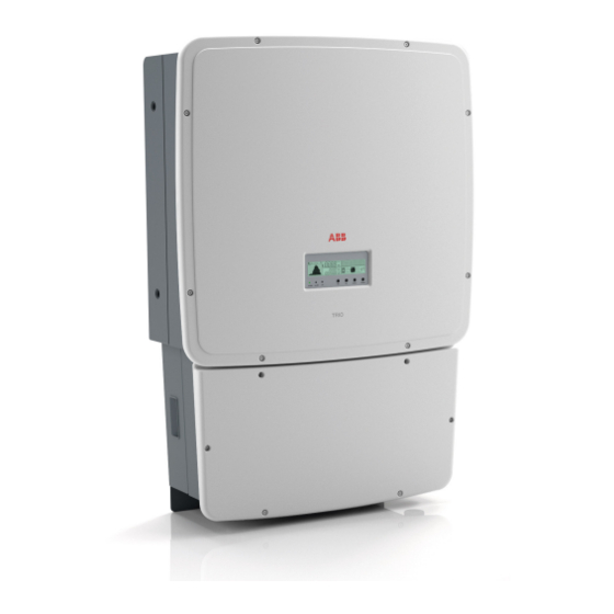
- Page 2 ABB solar inverters Product manual TRIO-20.0/27.6-TL-US (20.0 to 27.6 kW)
- Page 3 ist of related manuals TRIO manuals and guides Code (English) TRIO-20.0_27.6-TL-OUTD-US (-A) BCM.00202.1 Quick Installation Guide - 2 -...
- Page 4 This manual covers only the details concerning the rapid shutdown components and how it is installed in the allowable ABB string inverters. Information concerning the equipment connected to this product is available from the respective manufacturers.
- Page 5 1 - Introduction and safety 2 - Installation location 3 - Mounting and wiring 4 - Operations 5 - Troubleshooting 6 - Maintenance 7 - Appendix TRIO-20.0-276-TL-OUTD-US(-A) Product manual BCG.00627.2_AB NA © Copyright 2015 ABB. All Rights Reserved. - 4 -...
-
Page 6: Table Of Contents
able of Contents Warnings in this document ........................9 Equipment safety warnings ....................9 ntroduction and safety ..........................9 General installation warnings....................10 Assembly warnings ......................10 Electrical connection warnings ..................10 Safety instructions ..........................11 General information ......................11 Thermal and voltage hazard ....................11 Clothing and protective devices ..................12 Location of safety notices and labels ................12 Appropriate usage ..........................12 Conditions of Use .......................12... - Page 7 Independent or parallel configuration of inputs ................36 Dual MPPT configuration – independent mode ..............36 Single MPPT configuration – parallel mode (non-AFD models) ........37 Setting the input mode switch a01 ...................37 Connection to the PV field (DC side) ....................40 Connection of DC inputs -S model ...................40 Connection of DC inputs -S1, –S1A, and -S1B models ..........41 String protection -S1, -S1A, and –S1B models ..............41 Grid output connection (AC side) .......................42...
- Page 8 aintenance ............................87 Routine maintenance ...........................87 Recommended system maintenance ....................88 Preventative maintenance ........................88 Storage and dismantling ........................89 ppendix ..............................91 System description ..........................91 Protective devices within the inverter ....................92 Ground fault detection and interruption scheme ................93 Topographic diagram of the equipment ....................94 Efficiency curves ..........................96 Voltage and temperature derating due to altitude ................97 Automatic power reduction .........................98...
- Page 9 This page is intentionally blank. - 8 -...
-
Page 10: Warnings In This Document
Introduction and safety arnings in this document This is a list of special safety symbols used in this manual that highlight potential safety risks and/or useful information. The symbol usage is described below: CAUTION The reader should stop, use caution and fully understand the operations explained before proceeding. -
Page 11: General Installation Warnings
PV system disconnection and protection for the AC output circuit. Connect only to a circuit provided with the maximum branch OCPD in accordance with the CSA document available at www.abb.com/solarinverters and listed in the technical data sheet of the appendix, section 7. - 10 -... -
Page 12: Safety Instructions
The equipment has been manufactured in accordance with the strictest accident-prevention regulations and supplied with safety devices suitable for the protection of components and operators. Inform ABB about non-standard installation conditions. It is essential to provide operators with correct information. They must read and comply with the technical information given in the manual and any other attached documentation. -
Page 13: Clothing And Protective Devices
1- Introduction and safety Anytime the inverter has been disconnected from the AC utility grid, use extreme caution, as some components can retain charge sufficient to create a shock hazard and may need time to dissipate the charge. To minimize occurrence of such conditions, comply with all corresponding safety symbols and markings present on the unit and in this manual. -
Page 14: Environmental Conditions
MPPT channels associated with all ABB string inverters, and has two current sensors and associated circuitry to identify the presence of a series DC arc fault at the input of either inverter MPPT channel. -
Page 15: Available Versions
A description of the wiring box configurations available can be found below. 20.0 kW MODELS TRIO-20.0-TL-OUTD-S-US-480 Dimensions (HxWxD): TRIO-20.0-TL-OUTD-S-US-480-A 41.7 x 27.6 x 11.5 in TRIO-20.0-TL-OUTD-S1-US-480... -
Page 16: Regulatory Label
Made in Italy to the equipment. The nameplate SOLAR GRID TIED INVERTER UTILITY INTERACTIVE - TRANSFORMERLESS INVERTER shown is affixed to the inverter and MODEL: TRIO-20.0-TL-OUTD-S-US-480-A provides the following information: DC RATING 1. Certification Nominal Input Operating Voltage 700 V 2. - Page 17 1- Introduction and safety This page is intentionally blank. - 16 -...
-
Page 18: Transportation And Handling
ABB packages and protects individual components using suitable means to make their transport and subsequent handling easier. Due to the weight and complexity of this equipment, ABB recommends the process of loading and unloading of this equipment be done by an experienced or specialized staff knowledgeable in material handling. - Page 19 81510000077 COMPONENTS FOR NON-AFD MODELS ONLY QTY/PART NO Jumpers for configuration 2 each of parallel input channels Reliance RAQ2-16, ABB JB12-2 OPTIONAL COMPONENT QTY/PART NO Optional lifting kit includes 1 kit M12 handles and eyebolts for 3M2200HNDK0 lifting the inverter...
-
Page 20: Handling The Trio
2 - Installation andling the TRIO The TRIO inverter and wiring box are shipped as separate components within a common container. They are designed to be installed individually allowing an easier installation process. The inverter unit weighs 143 pounds or less, depending on the version, and should always be lifted by two persons. -
Page 21: Select The Installation Location
• Do not install in direct sunlight. If the preferred mounting location is in direct sunlight, install the ABB Sun Shield on the inverter in order to provide the necessary shade. • Do not install in small closed spaces where air cannot circulate freely. -
Page 22: Installation Position
2 - Installation nstallation position When choosing the installation location and position, comply with the following conditions: • Install on a wall or strong structure capable of bearing the weight. • Install vertically with a maximum incline of +/- 5°. If the mounted inverter is tilted to an angle greater than the maximum noted, heat dissipation can be inhibited, and may result in less than expected output power. - Page 23 2 - Installation For multiple-inverter installations, position the inverters side-by-side, maintaining minimum clearances. If the space available does not allow the side-by-side arrangement, multiple inverters can be placed in the staggered arrangement shown; this minimizes heat dissipation from lower 6” 6”...
-
Page 24: Mounting And Wiring
Mounting and wiring abeled illustration of TRIO 01 mounting bracket 02 wiring box 03 inverter 04 coupling connector cover 05 clamp screw 06 optional handles 07 connector screws 08 wiring box cover 31 bottom locking tab for securing mounting bracket to wiring box and inverter, can also be used as exterior grounding electrode, if... - Page 25 3 - Mounting and wiring Conduit entries for all versions are located on the bottom of the wiring box along with the DC disconnect switch handle 14. Conduit entries are illustrated below. The appropriate conduit connector must be used in order to maintain required spacing between wiring groups and preserve the integrity of the NEMA 4X environmental rating.
-
Page 26: Wall Mounting
3 - Mounting and wiring all mounting When mounting the TRIO, first secure the mounting bracket to the desired location and then install the wiring box followed by the inverter unit. Included in the shipping package is a mounting kit with stainless steel screws and wall anchors for mounting the powder coated, stainless steel bracket to a wall or structure The overall dimensions of the mounting bracket are expressed in millimeters and inches. -
Page 27: Installation Method With Flexible Conduit
3 - Mounting and wiring The process of joining the inverter and wiring box together should be completed before the conduit is secured. When completely tightened the wiring box will move up to meet the inverter. It is recommended to employ flexible conduit methods to allow for easy removal of the inverter, if ever required. - Page 28 3 - Mounting and wiring Remove the front cover 08 from • the wiring box. • Install the wiring box 02 onto the bracket by inserting the heads of the rear screws into the slots in the bracket. Note: it is not necessary to install the inverter 03 at this time.
- Page 29 3 - Mounting and wiring • Join together the wiring box and inverter by tightening the coupling screw 05, working from the underside of the wiring box. • Using a 20mm socket, tighten the clamp screw 05 to lift the inverter wiring box toward the inverter until mating connectors of the wiring box and inverter chassis seat fully.
-
Page 30: Installation Method With Rigid Conduit
3 - Mounting and wiring • Once the wiring box and inverter are connected, screw in the two connector screws 07 located inside the wiring box to fully lock and seal the connection. • Using a 13mm socket wrench, finish tightening each of the two connector screws 07 to at least 13.3-14.75 ft-lbs (18-20Nm) torque. -
Page 31: Wiring Details
The TRIO is designed without an isolation transformer and is intended to be installed per NFPA 70, 690.35 with an ungrounded PV array. C overcurrent protection To protect the AC connection line of the inverter, ABB recommends the following characteristics when installing a device for protection against overcurrent: TRIO-20.0-TL US TRIO-27.6-TL US... -
Page 32: Wiring Box Components
3 - Mounting and wiring iring box components There are four models of the wiring box available for either the 20.0 kW or 27.6 kW versions. Each model is available with or without arc fault detection (AFD). The major differences between the wiring box layouts are illustrated after the descriptions in the table below. -
Page 33: Trio-Xx.x-Tl-Outd-S-Us-480
3 - Mounting and wiring RIO-XX.X-TL-OUTD-S-US-480 • RIO-XX.X-TL-OUTD-S-US-480-A - 32 -... -
Page 34: Trio-Xx.x-Tl-Outd-S1-Us-480
3 - Mounting and wiring RIO-XX.X-TL-OUTD-S1-US-480 RIO-XX.X-TL-OUTD-S1-US-480-A - 33 -... -
Page 35: Trio-Xx.x-Tl-Outd-S1A-Us-480
3 - Mounting and wiring RIO-XX.X-TL-OUTD-S1A-US-480 RIO-XX.X-TL-OUTD-S1A-US-480-A - 34 -... -
Page 36: Trio-Xx.x-Tl-Outd-S1B-Us-480
3 - Mounting and wiring RIO-XX.X-TL-OUTD-S1B-US-480 RIO-XX.X-TL-OUTD-S1B-US-480-A - 35 -... -
Page 37: Independent Or Parallel Configuration Of Inputs
3 - Mounting and wiring ndependent or parallel configuration of inputs The TRIO Inverters have dual inputs with independent maximum power point tracking (MPPT) control. When operated in the dual input mode, the inverter can optimize two independent arrays. Each of the inputs is dedicated to a separate array with independent maximum power point tracking (MPPT) control. -
Page 38: Single Mppt Configuration - Parallel Mode (Non-Afd Models)
3 - Mounting and wiring ingle MPPT configuration – parallel mode (non-AFD models) In the PARallel mode, the two channels are connected in parallel and strings of photovoltaic modules having the same type and number of modules in series can be connected in parallel to the single channel. - Page 39 In order to connect the wires, remove the four screws in place and remove the cover. Depending on the brand of the terminal block (Chengdu Reliance or ABB) mounted inside the string combiner box, two different type of jumpers are provided in the product’s accessory bag.
- Page 40 3 - Mounting and wiring 1) Remove the removable transparent cover screws, lift it off, and put it aside. 2) A screwdriver is required to tighten the screws incorporated in the copper jumper type A.Tighten the screws to at least 53 in.-lbs (6 Nm) of torque to ensure a low resistance connection. Both jumpers need to be mounted for proper operation.
-
Page 41: Connection To The Pv Field (Dc Side)
3 - Mounting and wiring onnection to the PV field (DC side) WARNING! The DC disconnect switch (14) disconnects ONLY the DC current from the photovoltaic modules when the switch is open in the OFF position. It DOES NOT disconnect the AC connection to the grid. -
Page 42: Connection Of Dc Inputs -S1, -S1A, And -S1B Models
3 - Mounting and wiring onnection of DC inputs -S1, –S1A, and -S1B models Remove the threaded plastic plug and nut from the DC cable opening 11 and insert the appropriate conduit fitting. Tighten to the chassis to ensure NEMA 4X compliance. After reading the two CAUTION labels in place on the DC fuse blocks 22, remove them and then open all fuse holders before connecting the PV strings. -
Page 43: Grid Output Connection (Ac Side)
3 - Mounting and wiring rid output connection (AC side) • For suitable wire size (AWG), refer to NFPA National Electrical Code, Table 310.15(B)(16) (formerly Table 310.16) for US. • Use only Copper (Cu) wire rated for 75°C or 90°C (167°F or 194°F), solid or with type B or type C stranding (19 strands maximum). -
Page 44: Connection To The Ac Terminal Block
3 - Mounting and wiring • Lightly press the screwdriver tip toward the wire slot until the clamp opens; hold the clamp open with the screwdriver. • Insert the conductor into the socket until seated. • Release the pressure on the screwdriver and remove it from the slot. •... -
Page 45: Auxiliary Grounding Electrode Conductor (Gec)
3 - Mounting and wiring uxiliary grounding electrode conductor (GEC) Transformerless inverters do not required a grounding electrode conductor (GEC). A GEC is required only when a DC bonding jumper is present. Because transformerless inverters operate from floating arrays, neither side (POS or NEG) of the array is bonded to ground; hence, no internal bonding jumper exists. -
Page 46: Labeled Illustration Of Communication Card 09
3 - Mounting and wiring abeled illustration of communication card 09 A removable plastic cover prevents access to the section of the wiring box where the communication card resides. In order to access this area, remove the four screws in place and remove the cover. Ref. -
Page 47: Connections To The Communication Card
CARD block a07 (+T/R, -T/R and GND). 1) SERVICE/PC - dedicated line using AURORA Protocol for the connection of ABB monitoring and service equipment. PC port works only on AURORA Protocol. Baud rate is fixed at 19200 bit/s. 2) MODBUS/PMU - dedicated line for MODBUS RTU communications. -
Page 48: Daisy Chain Units For Connection To A Monitoring System
3 - Mounting and wiring The PC port is used by ABB service personnel for firmware upgrade, troubleshoot- ing and maintenance. When service interventions are required, user SCADA sys- tems will need to be temporarily disconnected. It is highly recommended that the Service/PC bus be interconnected between the inverters and brought to a terminal strip at the data logger location. -
Page 49: Remote On/Off A07
Adaptors equivalent to the AURORA PVI-USB-RS-485_232 which may also be used for this purpose can be found on the market; however, they have not been specifically tested and ABB cannot guarantee correct operation of the connection. These devices may also require external termination impedance, whereas this is not necessary with the AURORA PVI-USB-RS-485_232. -
Page 50: Auxiliary +5 V Output A07
3 - Mounting and wiring The devices to be connected to the output must comply with the following requirements: Direct current: Maximum Reverse Voltage: 10 V, Maximum Current: 8 mA. uxiliary +5 V output a07 Included on connector a07 is an auxiliary 5 V output. The maximum allowed absorption by this auxiliary supply voltage is 100 mA. -
Page 51: Environmental Sensors A06
3 - Mounting and wiring Alarm (configurable): the relay switches whenever there is an alarm (Error) or a Warning, which has been previously selected by the user through the dedicated menu. If the N/O (or N/C) contact is chosen, the contact will stay open (or closed) until the inverter reports an error or a warning out of those selected from the menu. -
Page 52: Auxiliary +24 V Service Output A06
For each analog sensor, AN1 and AN2, it is also necessary to set the switch, a03 or a04, to select whether the reading is in Volts or mA. Connection diagrams for the main sensors marketed by ABB can be found in the Appendix, section 7. -
Page 53: Saving The Country Standard And Language
3 - Mounting and wiring To change the settings, use a small flat head screwdriver and move the dial of the left-most switch to line up with position 1 on the rotary dial a02, and the second switch (right-most) to line up with position A on the dial. (If a switch position not assigned to a grid standard is selected, “Invalid Selection”... -
Page 54: Operations
One of the first rules for preventing damage to the equipment and injury to the operator is to have a thorough knowledge of the user interface operations. ABB cannot be held responsible for damage to the equipment or the operator if caused by incompetence, insufficient qualifications or lack of training. -
Page 55: Display And Keypad
4 - Operations isplay and keypad There are three indicators on the LED panel and four buttons on the keypad. LEDs indicate the operating state of the inverter. The keypad is used to review data on the cyclical display area b10 and access the data logged internally on the TRIO, using the menus described in this section. -
Page 56: Led Indicators
4 - Operations ED indicators In their various combinations, the LEDs can indicate conditions that are different from the single one. The table below shows the possible combinations of activation of the LEDs in relation to the operating state of the inverter. Warning and Error messages referenced below are described in Troubleshooting, section 5. -
Page 57: Descriptions Of Symbols And Display Fields
4 - Operations escriptions of symbols and display fields The operating parameters of the equipment can be viewed on the display 23 and include warnings, alarms, channels, voltages, etc. During operation, the display cycles through the various operating parameters described below. b1 RS-485 data transmission Power graph b15 DC/AC circuit... -
Page 58: Statistics Menu
4 - Operations During regular operation, the display will cycle through general information shown in the diagram on the right. To lock the display on any of the information screens, press and hold the ENTER button until the padlock symbol appears (see b20 in the table on page 56) In the data cycling mode, the icon at location b20 changes from a padlock to a two-... -
Page 59: Settings Menu
4 - Operations Partial - Displays partial statistics using a counter that can be reset*. • Time: Partial operating time since the counter was activated. • E-par: Partial energy produced since the counter was activated. • PPeak: Peak power value measured since the partial counter was activated. •... - Page 60 4 - Operations New Address Settings Address Display Set Light Password Advanced Contrast Service Password XXXX Buzzer 0000 New PW (four digits) Name Power Graph Cash Val/kwH 00.50 Time Time Date Language English Set Vstart1 Production Vstart Set Vstart 2 Alarm Alarm Enable...
- Page 61 UP and DOWN keys on the inverter display panel, scroll to select the values for modification. WARNING! ABB cannot be held responsible for any negative effects resulting from modifications of inverter set points. The set points in the table below should only be changed with the written permission of the local utility.
- Page 62 4 - Operations Parameter Definition Default Value Adjustable Ranges SET F<< Indicates the value of the absolute under frequency set 57.0 Hz 59.8 Hz to 55.0 Hz point below which the inverter disconnects from the grid SET U> Indicates the value of the intermediate over voltage set 110% of (110% x V ) to...
- Page 63 4 - Operations Parameter Definition Default Value Adjustable Ranges SET TIME Indicates the time the inverter takes to connect to the 30 sec 2 sec to Conn 1 grid for the first time (not after grid fault). 300 sec SET TIME Indicates the time the inverter takes to connect to the 300 sec 2 sec to...
- Page 64 Change the activation voltage only if necessary. A configuration program that can help to correctly size the photovoltaic system is available on at http://www.stringsizer. abb.com Alarm - This section of the menu allows programming of the alarm relay function (available as a normally open contact –...
- Page 65 4 - Operations Alarm: the relay switches when there is an alarm (Error) on the inverter. No switching occurs when there is a Warning. When N/O (or N/C) contact is chosen, it will stay open (or closed) until the inverter reports an error; once an error is reported, the relay switches state and closes (or opens).
- Page 66 4 - Operations a. Enable/Disable: Enables/Disables the scan for identifying the system’s maximum power point. b. Scan Interval: this allows setting the interval of time between scans. The shorter the interval between scans, the greater the loss of production due to the fact that, during the scan, energy is transferred to the grid but not at the maximum power point.
-
Page 67: Information Menu
4 - Operations nformation menu The INFO menu provides information about the inverter and access to modify the country standard for grid connection. INFO Part No. Serial No. Firmware Actual value New Value Country selector Set New Value Residual time Part No. -
Page 68: Commissioning
4 - Operations ommissioning WARNING! Do not place any items on the inverter during operation. Do not touch the heat sink when the inverter is operating, as some parts may be hot and cause burns. The incoming voltage must not exceed the maximum values shown in the technical data in order to prevent damage to the equipment. - Page 69 4 - Operations Once the inverter is powered, icon b11 comes on to indicate that the voltage from the photovoltaic array has reached the Vstart threshold (voltage necessary for connecting the inverter to the grid). For input voltages lower than Vstart, the icon b11 remains off, the Waiting Sun message is shown on the display and the voltage and current values are present (icons b12 and b13).
-
Page 70: Dynamic Behavior Of The Display During Operation
4 - Operations If there is not sufficient sunlight, the unit will repeat the procedure until all the parameters controlling connection to the grid (grid voltage and frequency, confirmation of no ground fault) are within the range. During this procedure, the green LED flashes ON and OFF. ynamic behavior of the display during operation If the MPPT scan function is enabled (on by default), icon b6 will be shown on the display and flash during scanning. - Page 71 4 - Operations This page is intentionally blank. - 70 -...
-
Page 72: Troubleshooting
Troubleshooting rc fault detection self-test errors For -A models only, an autotest circuit is included in the module design of the DC arc fault detection (AFD) solution. The AFD performs a self-test when the system is started, (e.g., every morning when sunlight is sufficient for grid connection). -
Page 73: Obtaining The Service Level Password
An advanced password can be provided to authorized installers to allow access to the service menu, upon completion of required documentation. Contact ABB technical support at 877-261-1374 to request this password. The password obtained is valid for 15 days. -
Page 74: Display Messages And Error Codes
(independent or parallel) inputs is carried out correctly. If the configuration of the PV array and the setting of the input channels are suitable, contact ABB technical support. - 73 -... - Page 75 Error inside the inverter that cannot be checked Internal Error are communication problems externally. If the problem persists (after switching the (Internal between the control devices inverter off and then on again), contact ABB technical Communication inside the inverter. support. Error) E006...
- Page 76 Error inside the inverter that cannot be checked Internal fault externally. If the problem persists (after switching the (Internal error) inverter off and then on again), contact ABB technical support. E010 Voltage at a specific part of If the error warning appears sporadically, it can...
- Page 77 Bulk Cap Fail regarding a problem in the bulk externally. If the problem persists (after switching the (Bulk capacitor capacitors. inverter off and then on again), contact ABB technical failure) support. E016 The alarm is generated when Error inside the inverter that cannot be checked...
- Page 78 If the problem persists (after switching the (Relay self-test relays of the DC-AC circuit part inverter off and then on again), contact ABB technical timeout) (inverter) is too long. This may support. indicate a problem associated with the aforesaid relays.
- Page 79 (DC-Injection out of supplied to the grid exceeds the the problem. If there is an inverter fault, contact ABB range) threshold of 0.5% of the rated technical support.
- Page 80 (imposed grid). If the problem is persistent (even after switching by regulations) to have a the inverter off and then on again), contact ABB measurement redundancy (two technical support. measurements on the same parameter carried out by two different circuits).
- Page 81 Error inside the inverter that cannot be checked IGBT not ready externally. If the problem persists (after switching the (IGBT not ready) inverter off and then on again), contact ABB technical support. E035 The inverter has been switched Switch on the inverter remotely. If the unit does not...
- Page 82 This may be caused by limits with ABB technical support. grid impedance that is too high. Towards the end of the timeout, the inverter limits the power to...
- Page 83 Check that the inverter is not exposed to direct Over Temp. measured inside the inverter’s sunlight. If in direct sunlight, order and install an ABB (Over temperature wiring box (high internal sun shield or create sufficient shade by other means from external box) temperature).
- Page 84 (Low input voltage- configuration “at the limit” relative that the configuration of the system is correct. If cannot connect to to the minimum input voltage of the input voltage exceeds the Vstart, contact ABB grid) the inverter. technical support. W002 Insufficient sunlight, wrong Check the inverter input voltage.
- Page 85 - If it does not exceed Vstart, check for the presence of sufficient irradiation and the correct composition of the system. - If it exceeds Vstart, contact ABB technical support. W012 Internal battery for maintenance Replace the battery (CR2032) with the inverter...
- Page 86 5 - Troubleshooting Display Message Causes Solution W023 Variation of the inverter’s date Notification of change that is saved in the historical Date/time mod. and time. This change is made log of inverter events. (Inner date/time through the display or advanced changed) configuration software.
-
Page 87: Making A Service Call
5 - Troubleshooting aking a service call When calling ABB technical support at 1-877-261-1374 to make a service call, the following information is required: Model number* Serial number* Week of production* State of the LCD: Status of warning lights (LEDs): what are the colors of the lights and are they steady or flashing? -
Page 88: Maintenance
Always use the personal protective equipment (PPE) provided by the employer and comply with the safety conditions in the Introduction and safety, section 1, of this manual. ABB accepts no liability if the periodic checks and maintenance cycles indicated in this manual and in the attached documentation are not complied with correctly, or if maintenance is entrusted to unqualified staff. -
Page 89: Recommended System Maintenance
6 - Maintenance ecommended system maintenance If not performed more often, ABB recommends having the systems checked after about five years of activity to maintain the correct working performance. Clean the photovoltaic modules every six months, at the change of season or as necessary. -
Page 90: Storage And Dismantling
If the equipment is not used immediately or is stored for long periods, check that it is packaged correctly and contact ABB technical support at 1-877-261-1374 for storage instructions. The equipment must be stored in well- ventilated indoor areas in a noncorrosive environment. Restarting after a long storage period requires the removal of oxidation and dust that may have settled inside the equipment if not suitably protected. - Page 91 6 - Maintenance This page is intentionally blank. - 90 -...
-
Page 92: Ppendix
Appendix ystem description TRIO grid-tied inverters provide the capability to supply the utility grid with energy obtained from photovoltaic modules. To efficiently use the DC generated by a photovoltaic field, it must be transformed into alternating current (AC) via a conversion process known as DC-AC inversion. This process is the basis of all grid-tied inverters and is achieved very efficiently by the inverter without the use of rotating elements. -
Page 93: Protective Devices Within The Inverter
Decisions about how to structure a photovoltaic system depend on a number of factors and considerations such as the type of modules, the availability of space, long-term energy production goals, etc. A configuration program to correctly size the photovoltaic system is on the the ABB website at www.stringsizer.abb.com. rotective devices within the inverter... -
Page 94: Ground Fault Detection And Interruption Scheme
7 - Appendix round fault detection and interruption scheme As required by UL1741 CRD 2010, the TRIO inverter incorporates two separate methods for detecting a ground fault in the ungrounded PV array, as described below: Method 1: Pre-Start (Static RISO) Any time conditions are suitable for the inverter to be connected to the grid, prior to connection internal circuitry measures the insulation resistance (RISO) of the PV array conductors relative to ground. -
Page 95: Topographic Diagram Of The Equipment
7 - Appendix opographic diagram of the equipment The block diagram on the next page displays the inverter’s operational parts. The main blocks are the input boost converters and the output inverter. Both the boost converters and the output inverter operate at high-switching frequencies, resulting in a compact size and relatively light weight. - Page 96 7 - Appendix - 95 -...
-
Page 97: Efficiency Curves
7 - Appendix fficiency curves The equipment was designed in compliance with energy conservation standards to avoid waste and unnecessary leakage. Graphs of the efficiency curves of the inverters are shown below. The efficiency curves are affected by technical parameters that are continually being developed and improved and should be considered approximate. TRIO 20.0kW efficiency curve 450 Vdc 700 Vdc... -
Page 98: Voltage And Temperature Derating Due To Altitude
7 - Appendix oltage and temperature derating due to altitude Certain conditions should be considered when choosing an installation location at high altitudes. Air pressure decreases as altitude above sea level increases. The reduced air density results in less effective heat dispersal, hence the need to reduce rated operating temperatures. -
Page 99: Automatic Power Reduction
7 - Appendix Example – temperature derating calculation for a TRIO-20.0/27.6-TL-US installed at 7500 feet: • The maximum rated temperature, for full power operation at sea level, from the TRIO-20.0/27.6-TL-US series datasheet, is 113°F (45°C). • The normalized temperature derating factor from the graph on page 97, at an altitude of 7500 feet is .945. •... - Page 100 7 - Appendix Power reduction due to temperature Power reduction due to ambient or inverter temperature depends on many operating parameters, such as input voltage, grid voltage and power available from the photovoltaic arrays. The inverter may reduce its output power during the day according to the value of these parameters.
- Page 101 7 - Appendix Power reduction due to input voltage The following graphs show the automatic reduction in output power when the input voltage is too high or too low. TRIO 20.0kW- Pout vs Vin parallel input configuration 25000 20000 15000 10000 5000 1000...
- Page 102 7 - Appendix TRIO 27.6kW- Pout vs. Vin parallel input configuration 30000 25000 20000 15000 10000 5000 1000 Vin [V] TRIO 27.6kW- Pin and Pout vs. Vin1/Vin2 Independent input configuration (max channel unbalance) 30000 Pout Vs Vin 25000 Pin1 (12800max) Vs Vin1 Pin2 (16000Wmax) Vs Vin2 20000 15000...
-
Page 103: Mppt Configuration Examples
7 - Appendix PPT configuration examples PV field characteristics MPPT configuration Notes • The photovoltaic array consists of For two active MPPTs in the independent strings having a different number of mode, each photovoltaic array is to be modules in series. connected to each of the inputs with a •... -
Page 104: Environmental Sensors
7 - Appendix nvironmental sensors Tables containing the technical data of the main sensors available from ABB are shown below. External power TRIO Model Output signal supply compatible PVI-AEC-IRR 0...10Vdc PVI-AEC-IRR-T 0...10Vdc PVI-AEC-RAD-13TC 0...10Vdc PVI-AEC-RAD-13-TC-T 0...10Vdc PVI-AEC-CONV-T100 0...10Vdc PVI-AEC-T1000-INTEGR 0...10Vdc PVI-AEC-WIND-COMPACT 0...10Vdc... -
Page 105: Connection Diagrams For Environmental Sensors
7 - Appendix onnection diagrams for environmental sensors Connection diagrams for the main sensors sold by ABB are shown below: Each of the environmental sensors listed above, with the exception of the PVI-AEC-PYR-1300 Pyranometer should be connected directly to the analog input of the Trio inverter. This data is then transmitted along with the inverter’s data to the system’s data logger (VSN700 sold separately). -
Page 106: Technical Data And Types
7 - Appendix echnical data and types Type code TRIO-20.0-TL-OUTD TRIO-27.6-TL-OUTD Nominal output power 20000W 27600W Maximum output power 22000W 30000W Rated grid AC voltage 480V Input side (DC) Number of independent MPPT channels 2; Programmable for 1 MPPT Maximum usable power for each MPPT channel 12000W 16000W Absolute maximum voltage (V... -
Page 107: Technical Data And Types (Continued)
Safety approval Warranty Standard warranty 10 years Extended warranty 15 & 20 years Available models Standard with DC disconnect TRIO-20.0-TL-OUTD-S-US-480 TRIO-27.6-TL-OUTD-S-US-480 With DC disconnect, DC fuses and DC surge TRIO-20.0-TL-OUTD-S1-US-480 TRIO-27.6-TL-OUTD-S1-US-480 protection With DC disconnect, DC fuses, DC surge TRIO-20.0-TL-OUTD-S1A-US-480 TRIO-27.6-TL-OUTD-S1A-US-480... - Page 108 For more information on ABB products and services for solar applications, navigate to www.abb.com/solarinverters...
- Page 109 www.abb.com/solarinverters...