
Related Manuals for ABB PVI-3.0-TL-OUTD-S-US


Summary of Contents for ABB PVI-3.0-TL-OUTD-S-US
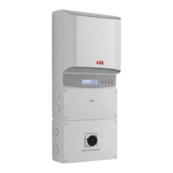
- Page 1 ABB solar inverters Product manual PVI-3.0-3.6-3.8-4.2-TL-OUTD-S-US (-A) (3.0 to 4.2 kW)
- Page 2 ist of related manuals UNO manuals and guides Code (English) PVI-3.0-3.6-3.8-4.2-TL-OUTD-US BCM.00161.1 (-A) Quick Installation Guide - 2 -...
- Page 3 IMPORTANT SAFETY INSTRUCTIONS This manual contains important safety instructions that must be followed during installation and maintenance of the inverter. SAVE THESE INSTRUCTIONS! Keep this document in a safe place near the inverter for easy access during installation and maintenance. THE INSTALLER MUST READ THIS DOCUMENT IN ITS ENTIRETY BEFORE INSTALLING OR COMMISSIONING THIS EQUIPMENT.
- Page 4 1 - Introduction and safety 2 - Installation location 3 - Mounting and wiring 4 - Operations 5 - Troubleshooting 6 - Maintenance 7 - Appendix PVI-3.0-3.6-3.8-4.2-TL-OUTD-S-US (-A) Product manual BCG.00681.1_AA NA Rev 1.0 © Copyright 2014 ABB. All Rights Reserved. - 4 -...
-
Page 5: Table Of Contents
ontents ntroduction and safety ........................7 Warnings in this document ........................7 Equipment safety warnings ....................7 General installation warnings....................8 Assembly warnings ......................8 Electrical connection warnings ...................8 Safety instructions ..........................9 General information ......................9 Thermal and voltage hazard ....................9 Clothing and protective devices ..................10 Location of safety notices and labels ................10 Appropriate usage ..........................10 Environmental conditions ....................10... - Page 6 perations ............................33 Monitoring and data transmission .....................33 Types of data available ......................33 User interface ............................33 Display and keypad ......................34 LED indicators ........................35 Cyclical display of general information................36 Statistics menu ........................37 Settings menu ........................38 Information menu ........................45 Commissioning .............................46 Connection of system to the grid ..................46 First phase - electric parameter monitoring ..............48 roubleshooting ..........................
-
Page 7: Introduction And Safety
Introduction and safety arnings in this document This is a list of special safety symbols used in this manual that highlight potential safety risks and/or useful information. The symbol usage is described below: CAUTION The reader should stop, use caution and fully understand the operations explained before proceeding. -
Page 8: General Installation Warnings
National Electric Code (ANSI/NFPA 70). See Maximum AC OCPD requirement in Appendix, section 7. The inverter should be connected only to a dedicated branch circuit. ABB DOES NOT provide AC output overcurrent protection; it is the responsibility of the end user to provide protection for the AC output circuit. -
Page 9: Safety Instructions
The equipment has been manufactured in accordance with the strictest accident-prevention regulations and supplied with safety devices suitable for the protection of components and operators. Inform ABB about non-standard installation conditions. It is essential to provide operators with correct information. They must read and comply with the technical information given in the manual and any other attached documentation. -
Page 10: Clothing And Protective Devices
1- Introduction and safety lothing and protective devices Appropriate Personal Protective Equipment (PPE) must be worn at all times when servicing this equipment under any conditions which may subject personnel to hazardous voltages or temperatures that are not touch-safe. All operations on the equipment should be performed with properly electrically insulated instruments. -
Page 11: Arc Fault Detection (Afd)
Processor (DSP) technology. The AFDI module has two independent channels, designed to accommodate the two independent MPPT channels associated with all ABB String inverters, and has two current sensors and associated circuitry to identify the presence of a series DC arc fault at the input of either inverter MPPT channel. -
Page 12: Regulatory Label
® Technical data in this manual does UL 1741 not supersede the data on the CSA-C22.2 No. 107.1-01 www.abb.com/solar Country of Origin Italy labels affixed to the equipment. SOLAR UTILITY INTERACTIVE TRANSFORMERLESS INVERTER The nameplate shown is affixed MODEL: PVI-3.0-OUTD-S-US... -
Page 13: I Nstallation Location
Due to the weight and complexity of this equipment, ABB recommends the process of loading and unloading of this equipment be done by an experienced or specialized staff knowledgeable in material handling. Where indicated or where there is a provision, eyebolts or handles can be inserted and used as lifting points. -
Page 14: Select The Installation Location
• Exposure to direct sunlight will increase the operational temperature of the inverter and may cause output power limiting. ABB recommends using a sun shade minimizing direct sunlight when the ambient air temperature around the unit exceeds 104°F/40°C. •... -
Page 15: Installation Position
2 - Installation location nstallation position When choosing the installation location and position, comply with the following conditions: • Install on a wall or strong structure capable of bearing the weight. • Install vertically with a maximum incline of +/- 5°. If the mounted inverter is tilted to an angle greater than the maximum noted, heat dissipation can be inhibited, and may result in less than expected output power. - Page 16 2 - Installation location - 16 -...
-
Page 17: Ounting And Wiring
10mm diameter and 75mm depth. When the wall is made of a different material (other than concrete) the installation should be done using adequate mounting material. ABB recommends always using stainless steel screws. Components included in mounting kit XAK.00060.0... - Page 18 3 - Mounting and wiring • Using the mounting bracket as a template, locate and mark the desired mounting location. • Using the four screws provided, level and mount the bracket to the surface using mounting holes B illustrated on previous page. •...
-
Page 19: Wiring Details
3 - Mounting and wiring iring details WARNING: Always respect the nominal ratings of voltage and current defined in the Appendix, section 7, when designing the system. Observe the following considerations in designing the photovoltaic system: • Maximum array DC voltage input to each MPPT circuit: 600 Vdc under any condition. •... - Page 20 3 - Mounting and wiring DC electrical schematics for front switchbox, AFD available on –A models only DC SWITCH INVERTER +IN1 +IN1 -IN1 -IN1 DC IN +IN2 +IN2 -IN2 -IN2 GRID GRID WARNING! The DC disconnect switch disconnects the DC PV panel current from the photovoltaic panels when the switch is in “OFF”...
- Page 21 3 - Mounting and wiring Table 3 2: switchbox internal components Label Details Label Details DC Disconnect Switch AC grid output terminals, Note 1 Signal conduit entry with plastic threaded AC main ground, Note 2 plug, ½: trade size AC conduit entry with plastic threaded plug; Array PE ground, Note 1 trade size 1”...
-
Page 22: Wiring Connections
3 - Mounting and wiring Models with a bottom switch use standard terminal MPPT MPPT blocks for array wiring and AC output terminals. AC, DC and GND (L) field wiring terminals should be tightened with 2.26Nm/20 in-lbs torque. Grounding electrode (K) should be tightened with 5.08Nm/45in-lbs torque. -
Page 23: Dc Array Connections
3 - Mounting and wiring C array connections WARNING! The DC disconnect switch disconnects ONLY the DC current from the photovoltaic panels when the switch is open in the OFF position. It DOES NOT disconnect the AC connection to the grid. To disconnect the inverter from the AC grid, an external, customer supplied AC switch must be used. -
Page 24: Independent Or Parallel Configuration Of Inputs
3 - Mounting and wiring ndependent or parallel configuration of inputs The inverters have dual inputs with independent maximum power point tracking (MPPT) control. When operated in the dual input mode, the inverter can optimize two independent arrays. Each of the inputs is dedicated to a separate array with independent maximum power point tracking (MPPT) control. -
Page 25: Setting The Input Mode Switch S1
3 - Mounting and wiring In order to operate in the parallel mode from a common array, it is necessary to electrically connect the input channels in parallel using the jumper cables provided with this inverter. In addition, the input mode switch S1 located on the inverter connection board must also be set to the parallel mode as described below. -
Page 26: Parallel Mode Bottom Switch Wiring Box And -S Version With Afd
3 - Mounting and wiring arallel mode bottom switch wiring box and -S version with In the inverter box, parallel the two MPPT inputs of terminal [–IN1 and –IN2] and [+IN1 and +IN2] as shown below, using the two #10 AWG jumper wires provided (one black and one red cable) to connect the input. - Page 27 3 - Mounting and wiring • AC grid wiring is connected through the inverter switchbox. • Run an approved raceway between inverter and external AC disconnect switch. • Make conduit entry through openings (B or E) shown in table 3-1. •...
- Page 28 3 - Mounting and wiring Communication and signal wiring connections Wiring for the RS-485 communication system and hardwired control options must be routed through the switchbox and into the main inverter chassis for termination. It is necessary to open the inverter cover to access the communication and signal wiring which is located on the inverter board.
-
Page 29: Serial Communication (Rs-485)
3 - Mounting and wiring erial communication (RS-485) The inverter the communication line cabling can be connected using the RJ45 connectors or using the terminal block. If the terminal blocks are used, the signal RTN, +T/R and –T/R have to be cabled. If the RJ45 plugs are used, the pin-out is reported below. Pin # Signal Description... -
Page 30: Addressing Each Inverter
3 - Mounting and wiring The recommended length of total communication cable line for all inverters in the system is 1,000 meters [1094 yards] or less, and this distance capability depends strongly on the cable type used and installation workmanship. Depending on the type of computer used, the cable line adaptor can be RS-485 to RS232 or RS-485 to USB. -
Page 31: Configurable Relay Connection (Alarm)
3 - Mounting and wiring onfigurable relay connection (Alarm) The inverter has a multi-function relay accessible at the terminal block labeled item R in table 3-3. Use the mating connector supplied with the inverter to simplify connections to the terminal block. The relay output can be configured to activate a visual and/or audible alarm or be utilized by another control such as a building control system. - Page 32 3 - Mounting and wiring - 32 -...
-
Page 33: Perations
One of the first rules for preventing damage to the equipment and injury to the operator is to have a thorough knowledge of the user interface operations. ABB cannot be held responsible for damage to the equipment or the operator if caused by incompetence, insufficient qualifications or lack of training. -
Page 34: Display And Keypad
4 - Operations isplay and keypad There are three indicators on the LED panel and four buttons on the keypad. LEDs indicate the operating state of the inverter. The keypad is used to review data in the two line display area and access the data logged internally on the inverter, using the menus described in this section. -
Page 35: Led Indicators
4 - Operations ED indicators In their various combinations, the LEDs can indicate conditions that are different from the single one. The table below shows the possible combinations of activation of the LEDs in relation to the operating state of the inverter. Warning and Error messages referenced below are described in Troubleshooting, section 5. -
Page 36: Cyclical Display Of General Information
4 - Operations yclical display of general information The two line display area consists of 2 lines with 16 characters per line. When moving through the menu using the buttons of the keypad, the display is used to: • display the operating state of the inverter and the statistical data •... -
Page 37: Statistics Menu
4 - Operations tatistics menu The Statistics menu is a view only display of internally logged inverter data. Last 7 days Statistics Lifetime Last month Partial Last 30 days Today Last xxx Last 365 days User period Start xxxxxxxx End xxxxxxxxx Lifetime - Displays the total statistics for lifetime operation: •... -
Page 38: Settings Menu
4 - Operations ettings menu The Settings menu requires a password which allows access to configuration and modification of the basic inverter settings. • Press ESC to open the main menus. • Scroll DOWN to Settings and press ENTER. • The password screen is populated in the display. - Page 39 Using the UP and DOWN keys on the inverter display panel, scroll to select the values for modification. WARNING! ABB cannot be held responsible for any negative effects resulting from modifications of inverter set points. The set points in the table below should only be changed with the written permission of the local utility.
- Page 40 4 - Operations Parameter Definition Default Adjustable Value Ranges SET U>> Indicates the value of the absolute over 120% of Fixed voltage set point beyond which the in- Nominal line verter disconnects from the grid. [120% to neutral of Nominal line to neutral Voltage] Voltage SET U<<...
- Page 41 4 - Operations Parameter Definition Default Adjustable Value Ranges SET F conn< Indicates the value of the intermediate 59.3 Hz 59.8 Hz to under frequency set point to allow the 57 Hz inverter to connect to the grid for the first time.
- Page 42 4 - Operations Parameter Definition Default Adjustable Value Ranges DISABLE U> Provides ability to enable/disable the Disable Disable or En- (10 min) parameter able “SET U>(10 min)” Disable U< Provides ability to enable/disable the In- Enable Disable or En- termediate Under Voltage Set point U< able Disable F>...
- Page 43 4 - Operations Alarm - This section of the menu allows programming of the alarm relay function (available as a normally open contact – N/O, and also as a normally closed contact – N/C). This contact can be used, for example, to activate a siren or a visual alarm, control the disconnect device of an external transformer, or control an external device.
- Page 44 4 - Operations Hardware access to the ON/OFF function is via terminals +R and -R, describe in section 3. When the function is active, • Turn OFF the inverter terminals by shorting terminals +R and –R. • Turn ON the inverter by removing the short between terminals +R and –R. •...
-
Page 45: Information Menu
4 - Operations nformation menu The INFO menu provides information about the inverter and access to modify the country standard for grid connection. Part No. - Displays the inverter part number. Serial No. - Displays the inverter serial number and the week (from 1 to 52) and year of manufacture. -
Page 46: Commissioning
4 - Operations ommissioning WARNING! Do not place any items on the inverter during operation. Do not touch the heat sink when the inverter is operating, as some parts may be hot and cause burns. The incoming voltage must not exceed the maximum values shown in the technical data in order to prevent damage to the equipment. - Page 47 4 - Operations • While the system checks for grid connection to be established (“Missing Grid”), the yellow LED next to the display turns on continuously, while the green LED is flashing. • When waiting for the input voltage to exceed 50Vdc (“Waiting Wind”), the green LED turns on steady.
-
Page 48: First Phase - Electric Parameter Monitoring
4 - Operations irst phase - electric parameter monitoring If the parameters measured in start up are correct, the system will proceed to the next checks. Type OUTD 1A) inverter part number. PN -------- 2A) inverter serial number and firmware revision level. 3A) E-tod : Daily energy output. -
Page 49: Troubleshooting
Troubleshooting rc fault detection self-test errors For -A models only, an autotest circuit is included in the module design of the DC ARC FAULT DETECTOR and INTERRUPTOR (AFDI) solution. The AFDI performs a self-test when the system is started, (i.e. every morning when sunlight is sufficient for grid connection). -
Page 50: Obtaining The Service Level Password
5 - Troubleshooting btaining the service level password An advanced password can be provided to authorized installers to allow access to the service menu upon completion of required documentation. Contact customer service at 877-261-1374 to request this password. The password obtained is valid for a period of 15 days. NOTE! Because the service level password is date sensitive, it is necessary to have the correct date and time set on the inverter display to successfully use the password. - Page 51 5 - Troubleshooting Display Message Causes Solution Ground Fault The alarm is generated when If possible, measure the insulation resistance us- Red LED ground leakage current is de- ing a megohmmeter positioned between the photo- tected in the DC section of the voltaic field (positive terminal short-circuited to the system.
- Page 52 5 - Troubleshooting Display Message Causes Solution E005 The alarm occurs when there Error inside the inverter that cannot be checked ex- Comm.Error are communication problems be- ternally. If the problem persists (after switching the Internal Communi- tween the control devices inside inverter off and then on again), contact customer cation Error the inverter.
- Page 53 5 - Troubleshooting Display Message Causes Solution E013 The alarm is generated only when Make sure the setting of the “IN MODE” switch has Wrong Mode the inverter is configured with been intentionally positioned on “PAR” and that the Wrong Input Mode parallel inputs.
- Page 54 5 - Troubleshooting Display Message Causes Solution E018 The alarm is generated when, If possible, measure the insulation resistance us- Ground Fault during normal operation of the ing a megohmmeter positioned between the photo- Leakage current fail inverter, a ground leakage cur- voltaic field (positive terminal short-circuited to the rent is detected in the DC sec- negative pole) and ground.
- Page 55 5 - Troubleshooting Display Message Causes Solution E022 Time taken to execute the au- Error inside the inverter that cannot be checked ex- Self-Test Error 4 totest carried out on the relays of ternally. If the problem persists (after switching the Relay self- test...
- Page 56 5 - Troubleshooting Display Message Causes Solution E025 Before connecting to the grid, the If possible, measure the insulation resistance us- Riso Low inverter measures the insulation ing a megohmmeter positioned between the pho- insulation resistance of the PV array com- tovoltaic field (positive terminal short-circuited to resistance pared to ground.
- Page 57 5 - Troubleshooting Display Message Causes Solution E029 Error in the internal measurement Error inside the inverter that cannot be checked Error Meas Z of the insulation resistance of the externally. The error occurs if the internal measure- ZGrid Measures PV array compared to ground ment is carried out before connection to the grid) If Fault...
- Page 58 5 - Troubleshooting Display Message Causes Solution E035 The inverter has been switched Switch on the inverter remotely. If the unit does Remote Off off remotely (remote OFF) and not switch on, disable the remote on/off function Waiting remote ON remains in waiting state for the and switch the equipment off completely and then signal that will switch it on again...
- Page 59 5 - Troubleshooting Display Message Causes Solution E056 Excessive temperature mea- Check that the inverter is not exposed to direct Over Temp. (from sured inside the inverter’s wiring sunlight. Wait for the temperatures to which the in- external box) box: verter is exposed to return to the operating range High internal temperature.
- Page 60 5 - Troubleshooting Display Message Causes Solution W009 Table fail W010 This error appears when there is Error inside the inverter that cannot be resolved Fan Fail malfunctioning of the fan(s) in- with external operations. If the alarm is persistently (Alarm not shown side the inverter.
-
Page 61: Making A Service Call
5 - Troubleshooting Display Message Causes Solution W019 Overvoltage surge arresters situ- Look at the inspection window present on each SPD AC protection ated on the AC side are dam- surge arrester (AC side). If it is red, the surge ar- open aged. - Page 62 5 - Troubleshooting - 62 -...
-
Page 63: Aintenance
Always use the personal protective equipment provided by the employer and comply with the safety conditions in section 1 of this manual. ABB accepts no liability if the periodic checks and maintenance cycles indicated in this manual and in the attached documentation are not complied with correctly, or if maintenance is entrusted to unqualified staff. -
Page 64: Recommended System Maintenance
6 - Maintenance ecommended system maintenance If not performed more often, ABB recommends having the systems checked after about 5 years of activity to maintain the correct working performance. Clean the photovoltaic panels every six months, at the change of season or as necessary. The performance of the system depends on the condition of the PV panels. -
Page 65: Storage And Dismantling
ABB CANNOT be held responsible for disposal of the equipment, displays, cables, batteries, etc. The customer must dispose of these substances, which are potentially harmful to the environment, in accordance with the regulations in force in the country of installation. - Page 66 6 - Maintenance - 66 -...
-
Page 67: Ppendix
Appendix ystem description ABB grid-tied inverters provide the capability to supply the utility grid with energy obtained from photovoltaic panels. To use the DC generated by a photovoltaic field efficiently, it must be transformed into alternating current (AC) via a conversion process known as DC-AC inversion. -
Page 68: Protective Devices Within The Inverter
These versions of ABB inverters utilize “high-frequency switching” transformers, to provide a high-level of gal- vanic isolation between inverter input (array) and output (grid). This circuitry provides galvanic isolation from the secondary (AC side), while maintaining very high performance in terms of energy yield and export. - Page 69 7 - Appendix arrays can be installed with different positions, facing different directions and with different string lengths; each array is controlled by an MPPT control circuit. The high efficiency and extra large heat dissipation system enables operation at maximum power over a broad range of ambient temperatures.
-
Page 70: Efficiency Curves
7 - Appendix fficiency curves The equipment was designed in compliance with energy conservation standards to avoid waste and unnecessary leakage. Graphs of the efficiency curves of the inverters are shown below. The efficiency curves are affected by technical parameters that are continually being developed and improved and should be considered approximate. -
Page 71: Automatic Power Reduction
7 - Appendix utomatic power reduction In order to maintain safe inverter operation under adverse environmental conditions or due to improper input voltages, the unit automatically reduces the amount of power it feeds to the grid. The conditions for power reduction due to environmental conditions and input voltage can occur at the same time, but the power reduction will always be determined by the more severe factor. - Page 72 7 - Appendix Output power with one DC section operating - 72 -...
-
Page 73: Technical Data And Types
7 - Appendix echnical data and types Type code PVI-3.0-OUTD-US PVI-3.6-OUTD-US PVI-3.8-OUTD-US PVI-4.2-OUTD-US Mechanical specifications 3300 Nominal output power 3000W 3600W 3800W 4200W 3000 3300 3300 3600 4000 4000 3300 4200 4200 4200 4600 4600 Maximum output power wattage Rated grid AC voltage 208V 240V 277V... - Page 74 For more information on ABB products and services for solar applications, navigate to www.abb.com/solarinverters...
- Page 75 www.abb.com/solarinverters...