Table of Contents
Advertisement
Quick Links
ELECYLINDER
Instruction Manual
EC-S6/S7/S6□H/S7□H
S6□AH/S7□AH
R6/R7/RR6/RR7/
RR6□H/RR7□H
RR6□AH/RR7□AH
Sixth Edition
ME3766-6A
Specifications
Installation
ch.
Wiring
ch.
Operation
ch.
Preventive/
ch.
Predictive Maintenance
Parameters
ch.
Troubleshooting
ch.
Maintenance and
ch.
Inspection
External Dimensions
ch.
Life
ch.
Warranty
ch.
Appendix
ch.
1
ch.
2
3
4
5
6
7
8
9
1 0
1 1
1 2
Advertisement
Table of Contents
Troubleshooting

Related Manuals for IAI EC-RR6*AH series


Summary of Contents for IAI EC-RR6*AH series
- Page 1 EC-S6/S7/S6□H/S7□H S6□AH/S7□AH ELECYLINDER R6/R7/RR6/RR7/ RR6□H/RR7□H RR6□AH/RR7□AH Instruction Manual Sixth Edition ME3766-6A Specifications Installation Wiring Operation Preventive/ Predictive Maintenance Parameters Troubleshooting Maintenance and Inspection External Dimensions Life Warranty Appendix...
- Page 2 • This instruction manual is an original document dedicated for this product. • This product cannot be used in ways not shown in this instruction manual. IAI shall not be liable for any result whatsoever arising from the use of the product in any other way than what is noted in the manual.
- Page 3 ELECYLINDER Instruction Manual Configuration Control Product name Instruction manual name number ELECYLINDER Quick Start Guide ME3765 Instruction Manual ELECYLINDER ME3766 (this document) RCM-101-MW/RCM-101-USB PC Compatible Software for RC/EC ME0155 Instruction Manual Touch Panel Teaching Pendant TB-02/02D Instruction Manual ME0355 TB-03 Instruction Manual Data Setter ME0375 Wireless communication...
-
Page 4: Table Of Contents
Contents Safety Guide ······························································································· Intro-1 Precautions for Handling ··············································································· Intro-9 International Standard Compliance ································································ Intro-11 Precautions for Handling Wireless Operation ··················································· Intro-12 Precaution for Axis Operation with Wireless Connection ···································· Intro-14 Part Names ······························································································ Intro-15 Chapter 1 Specifications Checking the product ······························································ 1-1 Components ································································································... - Page 5 Installation of slider type ·························································· 2-6 Installation surface ························································································ 2-6 Mounting orientation ······················································································ 2-7 Precautions regarding stainless steel sheet ························································ 2-8 Square nuts ································································································· 2-8 Body mounting ····························································································· 2-9 Mounting transported objects ········································································ 2-13 Installation of high rigidity slider type ········································· 2-14 Installation surface ······················································································...
- Page 6 Wiring connections (for cables)················································ 3-10 Power I/O cable ·························································································· 3-10 Power I/O cable connection ·········································································· 3-11 24VDC power supply wiring ·········································································· 3-12 PLC wiring ································································································· 3-13 Brake release wiring ···················································································· 3-14 Chapter 4 Operation Basic operation ······································································ 4-1 Teaching tool connections and testing operation ··························· 4-2 Teaching pendant connection ··········································································...
- Page 7 Home position adjustment ·············································································· 6-9 Smooth accel/decel setting ··········································································· 6-10 Current control setting at stop ········································································ 6-11 Wireless function setting ·············································································· 6-12 Power-saving setting ··················································································· 6-13 Chapter 7 Troubleshooting Troubleshooting confirmations ··················································· 7-1 Troubleshooting diagnosis ························································ 7-4 Troubleshooting with no alarm generated ···································· 7-6 Operation failure ···························································································...
- Page 8 Chapter 9 External Dimensions Slider type external dimensions ················································· 9-1 EC-S6 ········································································································ 9-1 EC-S7 ········································································································ 9-2 High rigidity slider type external dimensions (EC-S□□AH) ··············· 9-3 EC-S6□AH ·································································································· 9-3 EC-S7□AH ·································································································· 9-4 High rigidity slider type external dimensions (EC-S□□H) ················· 9-5 EC-S6□H ····································································································...
-
Page 10: Safety Guide
Safety Guide Safety Guide The Safety Guide is intended to permit safe use of the product and thus to prevent risks and property damage. Be sure to read it before handling the product. Intro-1... - Page 11 Safety Guide Safety Precautions for Our Products Common safety precautions for the use of robots in various operations are indicated here. Operation Precautions Model ● This product is not intended or designed for applications where high levels of Selection safety are required, and so cannot guarantee that human lives will be protected.
- Page 12 Safety Guide Operation Precautions Transportation ● When transporting heavy objects, do the work with two or more persons or utilize equipment such as a crane. ● When working with two or more persons, make it clear who is to be in charge and communicate well with each other to ensure safety.
- Page 13 (4) Locations where the product may come in contact with water, oil or chemical spray (2) Cable wiring ● Use IAI genuine cables for connecting the actuator and controller, and for the teaching tools. ● Do not scratch cables, bend them forcibly, pull them, coil them, snag them, or place heavy objects on them.
- Page 14 Safety Guide Operation Precautions Installation (4) Safety measures ● When working with two or more persons, make it clear who is to be in charge Startup and communicate well with each other to ensure safety. ● When the product is operating or in the ready mode, take safety measures (such as the installation of safety/protection fences) so that nobody can enter the area within the robot's movable range.
- Page 15 Safety Guide Operation Precautions Trial Operation ● When working with two or more persons, make it clear who is to be in charge and communicate well with each other to ensure safety. ● After teaching or programming, carry out trial operation step by step before switching to automatic operation.
- Page 16 Safety Guide Operation Precautions Maintenance ● When releasing the brake on a vertically oriented actuator, be careful that it does not fall under its own weight, catching the operator's hand or damaging Inspection workpieces. ● The slider or rod may be misaligned from the stop position if the servo is turned OFF.
- Page 17 Safety Guide Precaution Indications The safety precautions are divided into "Danger", "Warning", "Caution" and "Notice" according to the warning level, as follows, and described in the Instruction Manual for each model. Level Degree of risk to persons and property Symbol This indicates an imminently hazardous situation which, if the product Danger Danger...
-
Page 18: Precautions For Handling
Precautions for Handling Precautions for Handling 1. The Safety Guide attached with the product is intended to permit safe use of the product and thus to prevent risks and property damage. Be sure to read it before handling the product. 2. - Page 19 Precautions for Handling 5. Do not apply radial load and load moment to the rod. (For rod type) Loads can only be applied in the axial direction matching the rod axis. 6. If return operations are continued over a short distance, they may rapidly degrade the film of grease.
-
Page 20: International Standard Compliance
To be checked in EC Declaration of Conformity. EC Declaration of Conformity proving conformity to RE Directive may be modified without notice according to addition of conformed models, specification change and so on. Visit our homepage (http:/www.iai-robot/) or contact our sales site if necessary. -
Page 21: Precautions For Handling Wireless Operation
Precautions for Handling Wireless Operation Precautions for Handling Wireless Operation When the option for wireless communication support (model: WL, WL2) is selected, a wireless communication circuit board is built into the ELECYLINDER. Certificates and self-declarations regarding the wireless function are handled under the model name below for the wireless circuit board. - Page 22 - ผู ้ผลิ ต : IAI CORPORATION. - ช ื ่ อ โมเดล : IABL3826 - ประเทศผู ้ผลิ ต : ญี ่ ป ุ่ น (Made in Japan) - ผู ้นํ า เข ้า : IAI Robot (Thailand) Co., Ltd. Intro-13...
-
Page 23: Precaution For Axis Operation With Wireless Connection
Precautions for Axis Operation with Wireless Connection Precautions for Axis Operation with Wireless Connection Data Setter TB-03 (V2.30 or later) can operate the option model code -WL2 ELECYLINDER with wireless connection. For operation with wireless connection, secure safety by following the precautions below before use. -
Page 24: Part Names
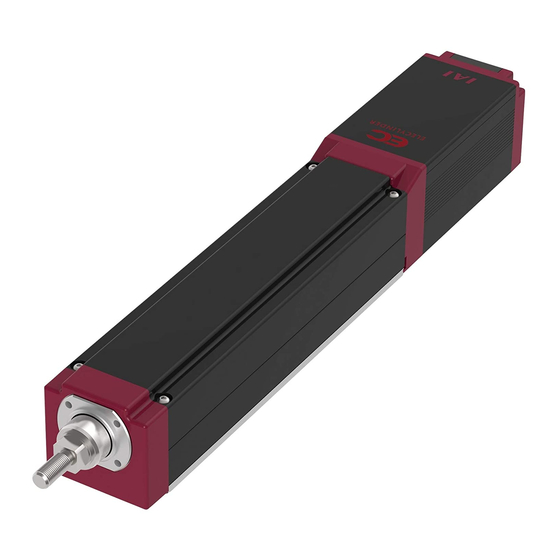
Part Names Part Names In this manual, the ELECYLINDER's left/right sides and motor/opposite sides are shown as in the figure below. Slider type Right side Slider Sheet Slider cover End cover Stainless steel sheet retainer Motor side Opposite side Sheet clamp Left side Status indicator LED... - Page 25 Part Names High rigidity slider type (EC-S□□H) Right side Slider cover Stainless steel sheet Slider Opposite side Motor side Sheet clamp Left side Track housing cover Power I/O connector Status LED Motor cover base Side cover End cover Base Motor cover Front cover Teaching port Rod type...
- Page 26 Part Names Radial cylinder type Right side Frame cover End cover Rod tip adaptor Opposite side Motor side Left side Teaching port Status LED Track housing cover Motor cover Base Front bracket Front cover Power I/O connector Motor cover base High rigidity radial cylinder type (EC-RR□□AH), High rigidity radial cylinder type (EC-RR□□H) Right side Frame cover...
- Page 27 Part Names Motor (built in controller) Status indicator LED Teaching port Power I/O connector [Teaching port] This connector is for the connection of a teaching pendant or PC software. When connecting, remove the cap. [Status indicator LED] The LED on the right side as seen from the motor side shows the servo ON/OFF status and alarm status, and the LED on the left side as seen from the motor side displays the wireless status.
- Page 28 Intro-19...
- Page 29 ELECYLINDER Chapter Specifications Checking the product ··············································· 1-1 Components ··········································································· 1-1 How to read the model nameplate ··············································· 1-2 How to read the model number ··················································· 1-3 Product list ············································································· 1-5 Mechanical specifications ·········································· 1-7 Slider type ·············································································· 1-7 High rigidity slider type (EC-S□□AH) ·········································· 1-19 High rigidity slider type (EC-S□□H) ············································...
- Page 30 Home reverse specification (model: NM) ···································· 1-96 PNP specification (model: PN) ················································· 1-96 Clevis bracket (model: QR) ······················································ 1-96 Oscillation receiving bracket (clevis) (model: QRPB) ····················· 1-96 Battery-less absolute encoder specification (model: WA) ··············· 1-96 Wireless communication specification (model: WL) ······················· 1-96 Wireless axis operation specification (model: WL2) ······················...
-
Page 31: Checking The Product
The following table shows the product configuration for the standard specification. See the packing list for the details of the enclosed components. In the unlikely case that any model number errors or missing parts come to light, contact your local IAI distributor. Body... -
Page 32: How To Read The Model Nameplate
1.1 Checking the product How to read the model nameplate Model number → Serial number → [Slider type, high rigidity slider type [Rod type nameplate position] nameplate position] [Radial cylinder type, high rigidity radial cylinder type nameplate position]... -
Page 33: How To Read The Model Number
1.1 Checking the product How to read the model number [Slider type, rod type, radial cylinder type] Wireless axis operation specification Wireless axis operation specification [High rigidity slider type (EC-S□□AH), high rigidity radial cylinder type (EC-RR□□AH)]... - Page 34 1.1 Checking the product [High rigidity slider type (EC-S□□H), high rigidity radial cylinder type (EC-RR□□H)]...
-
Page 35: Product List
1.1 Checking the product Product list [Slider type] 〈 〉represents vertical operation. [High rigidity slider type (EC-S□□AH)] 〈 〉represents vertical operation. [High rigidity slider type (EC-S□□H)] 〈 〉represents vertical operation. [Rod type] 〈 〉represents vertical operation. - Page 36 1.1 Checking the product [Radial cylinder type] 〈 〉represents vertical operation. [High rigidity radial cylinder type (EC-RR□□AH)] 〈 〉represents vertical operation. [High rigidity radial cylinder type (EC-RR□□H)] 〈 〉represents vertical operation.
-
Page 37: Mechanical Specifications
1.2 Mechanical specifications 1.2 Mechanical specifications Slider type [1] EC-S6 [Lead and Payload (Energy-Saving: Disabled)] Maximum payload Maximum Lead Model number pressing force Horizontal Vertical (mm) (kg) (kg) EC-S6S -① -② (-③) EC-S6H -① -② (-③) EC-S6M -① -② (-③) EC-S6L -①... - Page 38 1.2 Mechanical specifications [Payload by Speed/Acceleration (Energy-Saving: Disabled)] At low load capacity, the acceleration/deceleration can be increased. The maximum acceleration/deceleration is 1.0G in the horizontal direction and 0.5G in the vertical direction. For % input, 1.0G is set as 100%. Lead20 Lead 12 Orientation...
- Page 39 1.2 Mechanical specifications [Lead and Payload (Energy-Saving: Enabled)] Maximum payload Maximum Lead Model number pressing force Horizontal Vertical (mm) (kg) (kg) EC-S6S -① -② (-③) 0.75 EC-S6H -① -② (-③) EC-S6M -① -② (-③) EC-S6L -① -② (-③) Legend ①Stroke ②Cable length ③Option [Stroke and Max Speed (Energy-Saving: Enabled)]...
- Page 40 1.2 Mechanical specifications [Payload by Speed/Acceleration (Energy-Saving: Enabled)] At low load capacity, the acceleration/deceleration can be increased. The maximum acceleration/deceleration is 0.7G in the horizontal direction and 0.3G in the vertical direction. For % input, 1.0G is set as 100%. Lead20 Lead 12 Orientation...
- Page 41 1.2 Mechanical specifications [Actuator Specifications] Slider type moment direction (Pitching) (Yawing) (Rolling) Slider type overhang load length (L = 220mm or less) Ma direction Mb/Mc direction Caution If the actuator is used with excessive allowable moment and overhang load, it may not only lead to abnormal noise and vibration but also significantly reduce the life of the ELECYLINDER.
- Page 42 1.2 Mechanical specifications Calculate the recoil moment generated by the pressing force when performing pressing operation with the slider type. The allowable moment offset reference position is shown for the calculation. Configure the current limit value to ensure that the recoil moment does not exceed 80% of the (Ma/Mb) dynamic allowable moment given in the catalog specifications.
- Page 43 1.2 Mechanical specifications [2] EC-S7 [Lead and Payload(Energy-Saving: Disabled)] Maximum payload Maximum Lead Model number Horizontal Vertical pressing force (mm) (kg) (kg) EC-S7S -① -② (-③) EC-S7H -① -② (-③) EC-S7M -① -② (-③) EC-S7L -① -② (-③) Legend ①Stroke ②Cable length ③Option [Stroke and Max Speed(Energy-Saving: Disabled)]...
- Page 44 1.2 Mechanical specifications [Payload by Speed/Acceleration(Energy-Saving: Disabled)] At low load capacity, the acceleration/deceleration can be increased. The maximum acceleration/deceleration is 1.0G in the horizontal direction and 0.5G in the vertical direction. For % input, 1.0G is set as 100%. Lead24 Lead 16 Orientation Horizontal...
- Page 45 1.2 Mechanical specifications [Lead and Payload (Energy-Saving: Enabled)] Maximum payload Maximum Lead Model number pressing force Horizontal Vertical (mm) (kg) (kg) EC-S7S -① -② (-③) EC-S7H -① -② (-③) EC-S7M -① -② (-③) EC-S7L -① -② (-③) Legend ①Stroke ②Cable length ③Option [Stroke and Max Speed (Energy-Saving: Enabled)]...
- Page 46 1.2 Mechanical specifications [Payload by Speed/Acceleration (Energy-Saving: Enabled)] At low load capacity, the acceleration/deceleration can be increased. The maximum acceleration/deceleration is 0.7G in the horizontal direction and 0.3G in the vertical direction. For % input, 1.0G is set as 100%. Lead24 Lead 16 Orientation...
- Page 47 1.2 Mechanical specifications [Actuator Specifications] Slider type moment direction (Pitching) (Yawing) (Rolling) Slider type overhang load length (L = 280mm or less) Ma direction Mb/Mc direction Caution If the actuator is used with excessive allowable moment and overhang load, it may not only lead to abnormal noise and vibration but also significantly reduce the life of the ELECYLINDER.
- Page 48 1.2 Mechanical specifications Calculate the recoil moment generated by the pressing force when performing pressing operation with the slider type. The allowable moment offset reference position is shown for the calculation. Configure the current limit value to ensure that the recoil moment does not exceed 80% of the (Ma/Mb) dynamic allowable moment given in the catalog specifications.
-
Page 49: High Rigidity Slider Type (Ec-S□□Ah)
1.2 Mechanical specifications High rigidity slider type (EC-S□□AH) [1] EC-S6□AH [Lead and Payload (Energy-Saving: Disabled)] Maximum payload Maximum Lead Model number Horizontal Vertical pressing force (mm) (kg) (kg) EC-S6SAH -① -② (-③) EC-S6HAH -① -② (-③) EC-S6MAH -① -② (-③) EC-S6LAH -①... - Page 50 1.2 Mechanical specifications [Payload by Speed/Acceleration (Energy-Saving: Disabled)] At low load capacity, the acceleration/deceleration can be increased. The maximum acceleration/deceleration is 1.0G in the horizontal direction and 0.5G in the vertical direction. For % input, 1.0G is set as 100%. Lead 20 Lead 12 Orientation...
- Page 51 1.2 Mechanical specifications Caution Do not attempt to configure settings for acceleration/deceleration above the allowable values. This may lead to vibration, breakdown, or shortened product life. 1-21...
- Page 52 1.2 Mechanical specifications [Lead and Payload (Energy-Saving: Enabled)] Maximum payload Maximum Lead Model number pressing force Horizontal Vertical (mm) (kg) (kg) EC-S6SAH -① -② (-③) 0.75 EC-S6HAH -① -② (-③) EC-S6MAH -① -② (-③) EC-S6LAH -① -② (-③) Legend ①Stroke ②Cable length ③Option [Stroke and Max.
- Page 53 1.2 Mechanical specifications [Payload by Speed/Acceleration (Energy-Saving: Enabled)] At low load capacity, the acceleration/deceleration can be increased. The maximum acceleration/deceleration is 0.7G in the horizontal direction and 0.3G in the vertical direction. For % input, 1.0G is set as 100%. Lead 20 Lead 12 Orientation...
- Page 54 1.2 Mechanical specifications [Actuator Specifications] Keep the mounted object center of gravity at or below 1/2 the overhang length. Slider type moment direction (Yawing) (Pitching) (Rolling) Slider type overhang load length (L = 300mm or less) Ma direction Mb/Mc direction Caution If the actuator is used with excessive allowable moment and overhang load, it may not only lead to abnormal noise and vibration but also significantly reduce the life of the...
- Page 55 1.2 Mechanical specifications Calculate the recoil moment generated by the pressing force when performing pressing operation with the slider type. The allowable moment offset reference position is shown for the calculation. Configure the current limit value to ensure that the recoil moment does not exceed the (Ma/Mb) dynamic allowable moment given in the catalog specifications.
- Page 56 1.2 Mechanical specifications [2] EC-S7□AH [Lead and Payload (Energy-Saving: Disabled)] Maximum payload Maximum Lead Model number pressing force Horizontal Vertical (mm) (kg) (kg) EC-S7SAH -① -② (-③) EC-S7HAH -① -② (-③) EC-S7MAH -① -② (-③) EC-S7LAH -① -② (-③) Legend ①Stroke ②Cable length ③Option [Stroke and Max.
- Page 57 1.2 Mechanical specifications [Payload by Speed/Acceleration (Energy-Saving: Disabled)] At low load capacity, the acceleration/deceleration can be increased. The maximum acceleration/deceleration is 1.0G in the horizontal direction and 0.5G in the vertical direction. For % input, 1.0G is set as 100%. Lead 24 Lead 16 Orientation...
- Page 58 1.2 Mechanical specifications [Lead and Payload (Energy-Saving: Enabled)] Maximum payload Maximum Lead Model number Horizontal Vertical pressing force (mm) (kg) (kg) EC-S7SAH -① -② (-③) EC-S7HAH -① -② (-③) EC-S7MAH -① -② (-③) EC-S7LAH -① -② (-③) Legend ①Stroke ②Cable length ③Option [Stroke and Max.
- Page 59 1.2 Mechanical specifications [Payload by Speed/Acceleration (Energy-Saving: Enabled)] At low load capacity, the acceleration/deceleration can be increased. The maximum acceleration/deceleration is 0.7G in the horizontal direction and 0.3G in the vertical direction. For % input, 1.0G is set as 100%. Lead 24 Lead 16 Orientation...
- Page 60 1.2 Mechanical specifications [Actuator Specifications] 300mm Keep the mounted object center of gravity at or below 1/2 the overhang length. Slider type moment direction (Pitching) (Yawing) (Rolling) Slider type overhang load length (L = 300mm or less) Ma direction Mb/Mc direction Caution If the actuator is used with excessive allowable moment and overhang load, it may not only lead to abnormal noise and vibration but also significantly reduce the life of the...
- Page 61 1.2 Mechanical specifications Calculate the recoil moment generated by the pressing force when performing pressing operation with the slider type. The allowable moment offset reference position is shown for the calculation. Configure the current limit value to ensure that the recoil moment does not exceed the (Ma/Mb) dynamic allowable moment given in the catalog specifications.
-
Page 62: High Rigidity Slider Type (Ec-S□□H)
1.2 Mechanical specifications High rigidity slider type (EC-S□□H) [1] EC-S6□H [Lead and Payload (Energy-Saving: Disabled)] Maximum payload Maximum Lead Model number pressing force Horizontal Vertical (mm) (kg) (kg) EC-S6SH -① -② (-③) EC-S6HH -① -② (-③) EC-S6MH -① -② (-③) EC-S6LH -①... - Page 63 1.2 Mechanical specifications [Payload by Speed/Acceleration(Energy-Saving: Disabled)] At low load capacity, the acceleration/deceleration can be increased. The maximum acceleration/deceleration is 1.0G in the horizontal direction and 0.5G in the vertical direction. For % input, 1.0G is set as 100%. Lead20 Lead 12 Orientation Horizontal...
- Page 64 1.2 Mechanical specifications [Lead and Payload (Energy-Saving: Enabled)] Maximum payload Maximum Lead Horizontal Vertical Model number pressing force (mm) (kg) (kg) EC-S6SH -① -② (-③) 0.75 EC-S6HH -① -② (-③) EC-S6MH -① -② (-③) EC-S6LH -① -② (-③) Legend ①Stroke ②Cable length ③Option [Stroke and Max Speed (Energy-Saving: Enabled)]...
- Page 65 1.2 Mechanical specifications [Payload by Speed/Acceleration (Energy-Saving: Enabled)] At low load capacity, the acceleration/deceleration can be increased. The maximum acceleration/deceleration is 0.7G in the horizontal direction and 0.3G in the vertical direction. For % input, 1.0G is set as 100%. Lead20 Lead 12 Orientation...
- Page 66 1.2 Mechanical specifications [Actuator Specifications] Keep the mounted object center of gravity at or below 1/2 the overhang length. Slider type moment direction (Pitching) (Yawing) (Rolling) Slider type overhang load length (L = 300mm or less) Ma direction Mb/Mc direction Caution If the actuator is used with excessive allowable moment and overhang load, it may not only lead to abnormal noise and vibration but also significantly reduce the life of the...
- Page 67 1.2 Mechanical specifications Calculate the recoil moment generated by the pressing force when performing pressing operation with the slider type. The allowable moment offset reference position is shown for the calculation. Configure the current limit value to ensure that the recoil moment does not exceed the (Ma/Mb) dynamic allowable moment given in the catalog specifications.
- Page 68 1.2 Mechanical specifications [2] EC-S7□H [Lead and Payload (Energy-Saving: Disabled)] Maximum payload Maximum Lead Model number Horizontal Vertical pressing force (mm) (kg) (kg) EC-S7SH -① -② (-③) EC-S7HH -① -② (-③) EC-S7MH -① -② (-③) EC-S7LH -① -② (-③) Legend ①Stroke ②Cable length ③Option [Stroke and Max Speed (Energy-Saving: Disabled)]...
- Page 69 1.2 Mechanical specifications [Payload by Speed/Acceleration(Energy-Saving: Disabled)] At low load capacity, the acceleration/deceleration can be increased. The maximum acceleration/deceleration is 1.0G in the horizontal direction and 0.5G in the vertical direction. For % input, 1.0G is set as 100%. Lead24 Lead 16 Orientation Horizontal...
- Page 70 1.2 Mechanical specifications [Lead and Payload (Energy-Saving: Enabled)] Maximum payload Maximum Lead Model number Horizontal Vertical pressing force (mm) (kg) (kg) EC-S7SH -① -② (-③) EC-S7HH -① -② (-③) EC-S7MH -① -② (-③) EC-S7LH -① -② (-③) Legend ①Stroke ②Cable length ③Option [Stroke and Max Speed (Energy-Saving: Enabled)]...
- Page 71 1.2 Mechanical specifications [Payload by Speed/Acceleration (Energy-Saving: Enabled)] At low load capacity, the acceleration/deceleration can be increased. The maximum acceleration/deceleration is 0.7G in the horizontal direction and 0.3G in the vertical direction. For % input, 1.0G is set as 100%. Lead24 Lead 16 Orientation...
- Page 72 1.2 Mechanical specifications [Actuator Specifications] 300mm Keep the mounted object center of gravity at or below 1/2 the overhang length. Slider type moment direction (Pitching) (Yawing) (Rolling) Slider type overhang load length (L = 300mm or less) Ma direction Mb/Mc direction Caution If the actuator is used with excessive allowable moment and overhang load, it may not only lead to abnormal noise and vibration but also significantly reduce the life of the...
- Page 73 1.2 Mechanical specifications Calculate the recoil moment generated by the pressing force when performing pressing operation with the slider type. The allowable moment offset reference position is shown for the calculation. Configure the current limit value to ensure that the recoil moment does not exceed the (Ma/Mb) dynamic allowable moment given in the catalog specifications.
-
Page 74: Rod Type
1.2 Mechanical specifications Rod type [1] EC-R6 [Lead and Payload (Energy-Saving: Disabled)] Maximum payload Maximum Lead Model number Horizontal Vertical pressing force (mm) (kg) (kg) EC-R6S -① -② (-③) EC-R6H -① -② (-③) EC-R6M -① -② (-③) EC-R6L -① -② (-③) 12.5 Legend ①Stroke ②Cable length ③Option [Stroke and Max Speed... - Page 75 1.2 Mechanical specifications [Payload by Speed/Acceleration(Energy-Saving: Disabled)] At low load capacity, the acceleration/deceleration can be increased. The maximum acceleration/deceleration is 1.0G in the horizontal direction and 0.5G in the vertical direction. For % input, 1.0G is set as 100%. Lead20 Lead 12 Orientation Horizontal...
- Page 76 1.2 Mechanical specifications [Lead and Payload (Energy-Saving: Enabled)] Maximum payload Maximum Lead Model number Horizontal Vertical pressing force (mm) (kg) (kg) EC-R6S -① -② (-③) EC-R6H -① -② (-③) EC-R6M -① -② (-③) EC-R6L -① -② (-③) 12.5 Legend ①Stroke ②Cable length ③Option [Stroke and Max Speed (Energy-Saving: Enabled)]...
- Page 77 1.2 Mechanical specifications [Payload by Speed/Acceleration (Energy-Saving: Enabled)] At low load capacity, the acceleration/deceleration can be increased. The maximum acceleration/deceleration is 0.7G in the horizontal direction and 0.3G in the vertical direction. For % input, 1.0G is set as 100%. Lead20 Lead 12 Orientation...
- Page 78 1.2 Mechanical specifications [Actuator Specifications] [Pressing Force and Current Limit Value] Caution The relation of the current limit and the pressing force is a guideline at speed of 20mm/s. There is some variance in the actual pressing force. The variance increases when the current value is low.
- Page 79 1.2 Mechanical specifications [2] EC-R7 [Lead and Payload(Energy-Saving: Disabled)] Maximum payload Maximum Lead Model number Horizontal Vertical pressing force (mm) (kg) (kg) EC-R7S -① -② (-③) EC-R7H -① -② (-③) EC-R7M -① -② (-③) EC-R7L -① -② (-③) 1094 Legend ①Stroke ②Cable length ③Option [Stroke and Max Speed(Energy-Saving: Disabled)]...
- Page 80 1.2 Mechanical specifications [Payload by Speed/Acceleration(Energy-Saving: Disabled)] At low load capacity, the acceleration/deceleration can be increased. The maximum acceleration/deceleration is 1.0G in the horizontal direction and 0.5G in the vertical direction. For % input, 1.0G is set as 100%. Lead24 Lead 16 Orientation Horizontal...
- Page 81 1.2 Mechanical specifications [Lead and Payload (Energy-Saving: Enabled)] Maximum payload Maximum Lead Model number pressing force Horizontal Vertical (mm) (kg) (kg) EC-R7S -① -② (-③) EC-R7H -① -② (-③) EC-R7M -① -② (-③) 17.5 EC-R7L -① -② (-③) 1094 Legend ①Stroke ②Cable length ③Option [Stroke and Max Speed (Energy-Saving: Enabled)]...
- Page 82 1.2 Mechanical specifications [Payload by Speed/Acceleration (Energy-Saving: Enabled)] At low load capacity, the acceleration/deceleration can be increased. The maximum acceleration/deceleration is 0.7G in the horizontal direction and 0.3G in the vertical direction. For % input, 1.0G is set as 100%. Lead24 Lead 16 Orientation...
- Page 83 1.2 Mechanical specifications [Actuator Specifications] [Pressing Force and Current Limit Value] Caution The relation of the current limit and the pressing force is a guideline at speed of 20mm/s. There is some variance in the actual pressing force. The variance increases when the current value is low.
-
Page 84: Radial Cylinder Type
1.2 Mechanical specifications Radial cylinder type [1] EC-RR6 [Lead and Payload (Energy-Saving: Disabled)] Maximum payload Maximum Lead Model number Horizontal Vertical pressing force (mm) (kg) (kg) EC-RR6S -① -② (-③) EC-RR6H -① -② (-③) EC-RR6M -① -② (-③) EC-RR6L -① -② (-③) 12.5 Legend ①Stroke ②Cable length ③Option [Stroke and Max Speed... - Page 85 1.2 Mechanical specifications [Payload by Speed/Acceleration(Energy-Saving: Disabled)] At low load capacity, the acceleration/deceleration can be increased. The maximum acceleration/deceleration is 1.0G in the horizontal direction and 0.5G in the vertical direction. For % input, 1.0G is set as 100%. Lead20 Lead 12 Orientation Horizontal...
- Page 86 1.2 Mechanical specifications [Lead and Payload (Energy-Saving: Enabled)] Maximum payload Maximum Lead Model number pressing force Horizontal Vertical (mm) (kg) (kg) EC-RR6S -① -② (-③) EC-RR6H -① -② (-③) EC-RR6M -① -② (-③) EC-RR6L -① -② (-③) 12.5 Legend ①Stroke ②Cable length ③Option [Stroke and Max Speed (Energy-Saving: Enabled)]...
- Page 87 1.2 Mechanical specifications [Payload by Speed/Acceleration (Energy-Saving: Enabled)] At low load capacity, the acceleration/deceleration can be increased. The maximum acceleration/deceleration is 0.7G in the horizontal direction and 0.3G in the vertical direction. For % input, 1.0G is set as 100%. Lead20 Lead 12 Orientation...
- Page 88 1.2 Mechanical specifications [Actuator Specifications] [Pressing Force and Current Limit Value] Caution The relation of the current limit and the pressing force is a guideline at speed of 20mm/s. There is some variance in the actual pressing force. The variance increases when the current value is low.
- Page 89 1.2 Mechanical specifications [2] EC-RR7 [Lead and Payload(Energy-Saving: Disabled)] Maximum payload Maximum Lead Model number pressing force Horizontal Vertical (mm) (kg) (kg) EC-RR7S -① -② (-③) EC-RR7H -① -② (-③) EC-RR7M -① -② (-③) EC-RR7L -① -② (-③) 1094 Legend ①Stroke ②Cable length ③Option [Stroke and Max Speed(Energy-Saving: Disabled)]...
- Page 90 1.2 Mechanical specifications [Payload by Speed/Acceleration(Energy-Saving: Disabled)] At low load capacity, the acceleration/deceleration can be increased. The maximum acceleration/deceleration is 1.0G in the horizontal direction and 0.5G in the vertical direction. For % input, 1.0G is set as 100%. Lead24 Lead 16 Orientation Horizontal...
- Page 91 1.2 Mechanical specifications [Lead and Payload (Energy-Saving: Enabled)] Maximum payload Maximum Lead Model number pressing force Horizontal Vertical (mm) (kg) (kg) EC-RR7S -① -② (-③) EC-RR7H -① -② (-③) EC-RR7M -① -② (-③) 17.5 EC-RR7L -① -② (-③) 1094 Legend ①Stroke ②Cable length ③Option [Stroke and Max Speed (Energy-Saving: Enabled)]...
- Page 92 1.2 Mechanical specifications [Payload by Speed/Acceleration (Energy-Saving: Enabled)] At low load capacity, the acceleration/deceleration can be increased. The maximum acceleration/deceleration is 0.7G in the horizontal direction and 0.3G in the vertical direction. For % input, 1.0G is set as 100%. Lead24 Lead 16 Orientation...
- Page 93 1.2 Mechanical specifications [Actuator Specifications] [Pressing Force and Current Limit Value] Caution The relation of the current limit and the pressing force is a guideline at speed of 20mm/s. There is some variance in the actual pressing force. The variance increases when the current value is low.
- Page 94 1.2 Mechanical specifications Because the radial cylinder type has a linear guide built into the body, radial and moment loads can be applied to the rod. The applicable radial and moment loads must meet the following three conditions. 1. The radial load acting on the rod must not exceed the allowable value.
- Page 95 1.2 Mechanical specifications 3. The uniform load (*) acting on the rod must not exceed the allowable value. (*) Uniform load = Ma・Ka + Mb・Kb + Mc・Kc Dynamic Load Load Load Static allowable uniform uniform uniform Type allowable uniform coefficient coefficient coefficient uniform load...
- Page 96 1.2 Mechanical specifications Allowable offset amount, allowable overhang distance Offset amount Overhang distance (Rod perpendicular direction) (Rod length direction) Allowable overhang Type Allowable offset amount distance EC-RR6 100mm 100mm EC-RR7 100mm 100mm Caution Keep the radial load acting on the rod within the allowable offset amount and overhang distance for use.
-
Page 97: High Rigidity Radial Cylinder Type (Ec-Rr□□Ah)
1.2 Mechanical specifications High rigidity radial cylinder type (EC-RR□□AH) [1] EC-RR6□AH [Lead and Payload (Energy-Saving: Disabled)] Max. payload Max. push Lead Model force Horizontal Vertical (mm) (kg) (kg) EC-RR6SAH -① -② (-③) EC-RR6HAH -① -② (-③) EC-RR6MAH -① -② (-③) EC-RR6LAH -①... - Page 98 1.2 Mechanical specifications [Payload by Speed/Acceleration (Energy-Saving: Disabled)] At low load capacity, the acceleration/deceleration can be increased. The maximum acceleration/deceleration is 1.0G in the horizontal direction and 0.5G in the vertical direction. For % input, 1.0G is set as 100%. Lead 20 Lead 12 Orientation...
- Page 99 1.2 Mechanical specifications [Lead and Payload (Energy-Saving: Enabled)] Maximum payload Max. push Lead Model Horizontal Vertical force (mm) (kg) (kg) EC-RR6SAH -① -② (-③) EC-RR6HAH -① -② (-③) EC-RR6MAH -① -② (-③) EC-RR6LAH -① -② (-③) Legend ①Stroke ②Cable length ③Option [Stroke and Max.
- Page 100 1.2 Mechanical specifications [Payload by Speed/Acceleration (Energy-Saving: Enabled)] At low load capacity, the acceleration/deceleration can be increased. The maximum acceleration/deceleration is 0.7G in the horizontal direction and 0.3G in the vertical direction. For % input, 1.0G is set as 100%. Lead 20 Lead 12 Orientation...
- Page 101 1.2 Mechanical specifications [Actuator Specifications] 9N・m Overhang distance Offset amount (Rod length direction) (Rod perpendicular direction) [Pressing Force and Current Limit Value] Caution The relation of the current limit and the pressing force is a guideline at speed of 20mm/s. There is some variance in the actual pressing force.
- Page 102 1.2 Mechanical specifications [2] EC-RR7□AH [Lead and Payload (Energy-Saving: Disabled)] Maximum payload Max. push Lead Model Horizontal Vertical force (mm) (kg) (kg) EC-RR7SAH -① -② (-③) EC-RR7HAH -① -② (-③) EC-RR7MAH -① -② (-③) EC-RR7LAH -① -② (-③) 1094 Legend ①Stroke ②Cable length ③Option [Stroke and Max.
- Page 103 1.2 Mechanical specifications [Payload by Speed/Acceleration (Energy-Saving: Disabled)] At low load capacity, the acceleration/deceleration can be increased. The maximum acceleration/deceleration is 1.0G in the horizontal direction and 0.5G in the vertical direction. For % input, 1.0G is set as 100%. Lead 24 Lead 16 Orientation...
- Page 104 1.2 Mechanical specifications [Lead and Payload (Energy-Saving: Enabled)] Maximum payload Max. push Lead Model Horizontal Vertical force (mm) (kg) (kg) EC-RR7SAH -① -② (-③) EC-RR7HAH -① -② (-③) EC-RR7MAH -① -② (-③) 17.5 EC-RR7LAH -① -② (-③) 1094 Legend ①Stroke ②Cable length ③Option [Stroke and Max.
- Page 105 1.2 Mechanical specifications [Payload by Speed/Acceleration (Energy-Saving: Enabled)] At low load capacity, the acceleration/deceleration can be increased. The maximum acceleration/deceleration is 0.7G in the horizontal direction and 0.3G in the vertical direction. For % input, 1.0G is set as 100%. Lead 24 Lead 16 Orientation...
- Page 106 1.2 Mechanical specifications [Actuator Specifications] Overhang distance Offset amount (Rod length direction) (Rod perpendicular direction) [Pressing Force and Current Limit Value] Caution The relation of the current limit and the pressing force is a guideline at speed of 20mm/s. There is some variance in the actual pressing force. The variance increases when the current value is low.
- Page 107 1.2 Mechanical specifications Because the radial cylinder type has a linear guide built into the body, radial and moment loads can be applied to the rod. The applicable radial and moment loads must meet the following three conditions. 1. The radial load acting on the rod must not exceed the allowable value.
- Page 108 1.2 Mechanical specifications 2. The torque (Mc) acting on the rod must not exceed the allowable value. Torque (Mc) Rod tip static Rod tip dynamic Type (Note 1) allowable torque allowable torque EC-RR6□AH 9N·m 5.5N·m EC-RR7□AH 17.6N·m 10.5N·m (Note 1) The value assumes a basic rated life of 5,000km. 1-78...
- Page 109 1.2 Mechanical specifications 3. The uniform load (*) acting on the rod must not exceed the allowable value. (*) Uniform load = Ma・Ka + Mb・Kb + Mc・Kc Dynamic Load Load Load Static allowable uniform uniform uniform Type allowable uniform coefficient coefficient coefficient uniform load...
- Page 110 1.2 Mechanical specifications Allowable offset amount, allowable overhang distance Overhang distance Offset amount (Rod length direction) (Rod perpendicular direction) Allowable overhang Type Allowable offset amount distance EC-RR6□AH 100mm 100mm EC-RR7□AH 150mm 150mm Caution Keep the radial load acting on the rod within the allowable offset amount and overhang distance for use.
-
Page 111: High Rigidity Radial Cylinder Type (Ec-Rr□□H)
1.2 Mechanical specifications High rigidity radial cylinder type (EC-RR□□H) [1] EC-RR6□H [Lead and Payload (Energy-Saving: Disabled)] Max. payload Max. push Lead Model force Horizontal Vertical (mm) (kg) (kg) EC-RR6SH-①-② (-③) EC-RR6HH-①-② (-③) EC-RR6MH-①-② (-③) EC-RR6LH-①-② (-③) Legend ①Stroke ②Cable length ③Option Stroke and Max Speed (Energy-Saving: Disabled)]... - Page 112 1.2 Mechanical specifications [Payload by Speed/Acceleration (Energy-Saving: Disabled)] At low load capacity, the acceleration/deceleration can be increased. The maximum acceleration/deceleration is 1.0G in the horizontal direction and 0.5G in the vertical direction. For % input, 1.0G is set as 100%. Lead 20 Lead 12 Orientation...
- Page 113 1.2 Mechanical specifications [Lead and Payload (Energy-Saving: Enabled)] Maximum payload Max. push Lead Model Horizontal Vertical force (mm) (kg) (kg) EC-RR6SH-①-② (-③) EC-RR6HH-①-② (-③) EC-RR6MH-①-② (-③) EC-RR6LH-①-② (-③) Legend ①Stroke ②Cable length ③Option Stroke and Max Speed (Energy-Saving: Enabled)] Lead (mm) (mm) (mm)
- Page 114 1.2 Mechanical specifications [Payload by Speed/Acceleration (Energy-Saving: Enabled)] At low load capacity, the acceleration/deceleration can be increased. The maximum acceleration/deceleration is 0.7G in the horizontal direction and 0.3G in the vertical direction. For % input, 1.0G is set as 100%. Lead 20 Lead 12 Orientation...
- Page 115 1.2 Mechanical specifications [Actuator Specifications] Offset amount Overhang distance (Rod perpendicular direction) (Rod length direction) [Pressing Force and Current Limit Value] Caution The relation of the current limit and the pressing force is a guideline at speed of 20mm/s. There is some variance in the actual pressing force. The variance increases when the current value is low.
- Page 116 1.2 Mechanical specifications [2] EC-RR7□H [Lead and Payload (Energy-Saving: Disabled)] Maximum payload Max. push Lead Model Horizontal Vertical force (mm) (kg) (kg) EC-RR7SH-①-② (-③) EC-RR7HH-①-② (-③) EC-RR7MH-①-② (-③) EC-RR7LH-①-② (-③) 1094 Legend ①Stroke ②Cable length ③Option Stroke and Max Speed (Energy-Saving: Disabled)] Lead...
- Page 117 1.2 Mechanical specifications [Payload by Speed/Acceleration (Energy-Saving: Disabled)] At low load capacity, the acceleration/deceleration can be increased. The maximum acceleration/deceleration is 1.0G in the horizontal direction and 0.5G in the vertical direction. For % input, 1.0G is set as 100%. Lead 24 Lead 16 Orientation...
- Page 118 1.2 Mechanical specifications [Lead and Payload (Energy-Saving: Enabled)] Maximum payload Max. push Lead Model force Horizontal Vertical (mm) (kg) (kg) EC-RR7SH-①-② (-③) EC-RR7HH-①-② (-③) EC-RR7MH-①-② (-③) 17.5 EC-RR7LH-①-② (-③) 1094 Legend ①Stroke ②Cable length ③Option Stroke and Max Speed (Energy-Saving: Enabled)] Lead 100 to 300...
- Page 119 1.2 Mechanical specifications [Payload by Speed/Acceleration (Energy-Saving: Enabled)] At low load capacity, the acceleration/deceleration can be increased. The maximum acceleration/deceleration is 0.7G in the horizontal direction and 0.3G in the vertical direction. For % input, 1.0G is set as 100%. Lead 24 Lead 16 Orientation...
- Page 120 1.2 Mechanical specifications [Actuator Specifications] Overhang distance Offset amount (Rod length direction) (Rod perpendicular direction) [Pressing Force and Current Limit Value] Caution The relation of the current limit and the pressing force is a guideline at speed of 20mm/s. There is some variance in the actual pressing force. The variance increases when the current value is low.
- Page 121 1.2 Mechanical specifications Because the radial cylinder type has a linear guide built into the body, radial and moment loads can be applied to the rod. The applicable radial and moment loads must meet the following three conditions. 1. The radial load acting on the rod must not exceed the allowable value.
- Page 122 1.2 Mechanical specifications 3. The uniform load (*) acting on the rod must not exceed the allowable value. (*) Uniform load = Ma・Ka + Mb・Kb + Mc・Kc Dynamic Load Load Load Static allowable uniform uniform uniform Type allowable uniform coefficient coefficient coefficient uniform load...
- Page 123 1.2 Mechanical specifications Allowable offset amount, allowable overhang distance Overhang distance Offset amount (Rod length direction) (Rod perpendicular direction) Allowable overhang Type Allowable offset amount distance □ 100mm 100mm EC-RR6 □ 150mm 150mm EC-RR7 Caution Keep the radial load acting on the rod within the allowable offset amount and overhang distance for use.
-
Page 124: Duty Ratio
1.2 Mechanical specifications Duty ratio The duty ratio is the operating rate, shown in %, of the actuator operating time within one cycle. The duty ratio for the ELECYLINDER is limited to the values below. Use so that the duty ratio falls within the specified conditions based on ambient temperature. (all models) 1-94... -
Page 125: Options
1.3 Options 1.3 Options With brake (model: B) This is used to prevent the slider or rod from moving during power outages or when the servo is OFF. It can also be used to prevent the slider or rod from falling when mounted vertically. Tip adapter (flange) (model: FFA) This adapter is used to mount jigs, etc., on the rod tip with four bolts. -
Page 126: Home Reverse Specification (Model: Nm)
1.3 Options Home reverse specification (model: NM) The standard home position is on the motor side. However, the opposite side specification is selected if the home position direction is reversed in accordance with equipment layout or assembly direction. PNP specification (model: PN) I/O input/output specifications are NPN specification as standard. -
Page 127: Wireless Axis Operation Specification (Model: Wl2)
1.3 Options Wireless axis operation specification (model: WL2) The wireless axis operation specification includes a built-in wireless circuit board enabling wireless communication between the ELECYLINDER and the Data Setter. Specifying WL2 enables operation testing of axis operation (movement to forward and backward ends, jog operation, inching operation) as well as the operation via wireless communication enabled with WL. -
Page 128: Accessories
1.4 Accessories 1.4 Accessories Power I/O cable Supplied when length (value other than 0) is specified in the model number cable length. LS0/PE0 LS1/PS1 *ALM ● The wiring on the opposite side of the connector has not been processed. ● The cable length is available from 1m to 10m. Specify the length in increments of 1m. -
Page 129: Power I/O Connector
1.4 Accessories Power I/O connector Supplied when cable length is specified as "0" in the model number. Name Model number Quantity 1-1871940-6 Power I/O connector 1 pc (Tyco Electronics) 1-99... - Page 130 1-100...
-
Page 131: Installation
ELECYLINDER Chapter Installation Precautions for transportation ···································· 2-1 Installation and storage/preservation environment ·········· 2-4 Installation environment ···························································· 2-4 Storage/preservation environment··············································· 2-5 Installation of slider type ··········································· 2-6 Installation surface ··································································· 2-6 Mounting orientation ································································· 2-7 Precautions regarding stainless steel sheet ·································· 2-8 Square nuts ············································································... - Page 132 Body mounting ······································································ 2-23 Precautions regarding the rod ·················································· 2-29 External guide mounting ························································· 2-30 Mounting transported objects ··················································· 2-31 Installation of radial cylinder type ······························ 2-33 Installation surface ································································· 2-33 Mounting orientation ······························································· 2-34 Square nuts ·········································································· 2-35 Body mounting ······································································ 2-36 Mounting transported objects ···················································...
-
Page 133: Precautions For Transportation
2.1 Precautions for transportation 2.1 Precautions for transportation [Handling the package] ● Do not damage or drop the package. The package is not specially designed to withstand dropping or shock due to collision. ● Keep the unit in horizontal position for storage or transportation. ●... - Page 134 2.1 Precautions for transportation [Handling after unpacking] ● Carry the slider type by its base part and the rod type by its body frame. ● Do not carry the unit by its motor cover, side cover, or stainless steel sheet ●...
- Page 135 2.1 Precautions for transportation [Handling when assembled into machinery (system)] ● Secure sliders and rods to prevent sudden movement during transport. ● If the ELECYLINDER body or any moving part is overhanging,fix it appropriately to avoid large wobbles due to external vibration. When transporting without fixing the tip, do not apply impact of 0.3G or more.
-
Page 136: Installation And Storage/Preservation Environment
2.2 Installation and storage/preservation environment 2.2 Installation and storage/preservation environment Usage is possible in environments of pollution degree 2 or equivalent. Pollution degree 2: Environment in which generally only nonconductive pollution occurs, but temporary conductive pollution may occur due to condensation (IEC 60664-1) Installation environment Avoid the following locations for installation. -
Page 137: Storage/Preservation Environment
2.2 Installation and storage/preservation environment Storage/preservation environment ● For the storage and preservation environment, see the installation environment. However, give especial consideration to the prevention of condensation during long-term storage/preservation. ● Unless especially specified, desiccant is not included in the package at shipping. If the product is to be stored/preserved in an environment where condensation is anticipated, take condensation preventive measures. -
Page 138: Installation Of Slider Type
2.3 Installation of slider type 2.3 Installation of slider type Installation surface ● The body mounting surface should be a machined surface or a plane with similar accuracy, with flatness within 0.05mm/m. ● The mounting frame should have a structure rigid enough to prevent the generation of vibration. -
Page 139: Mounting Orientation
2.3 Installation of slider type Mounting orientation Type: EC-S6/S7 Horizontal installation Vertical installation Horizontal lateral installation Horizontal ceiling mount installation Caution When installing the unit vertically, keep the motor on top to the greatest extent possible. If the motor is installed on the bottom, the grease may separate due to long-term disuse, causing the base oil to flow into the motor part and leading to controller or motor/encoder breakdown. -
Page 140: Precautions Regarding Stainless Steel Sheet
2.3 Installation of slider type Precautions regarding stainless steel sheet ● During installation and transport, do not grasp or press on the stainless steel sheet. Otherwise, this may lead to stainless steel sheet damage. ● Although lateral or ceiling installation is possible, it may cause slackness or misalignment of the stainless steel sheet. -
Page 141: Body Mounting
2.3 Installation of slider type Body mounting [When using the T-slot on the base bottom] The unit has a T-slot at the bottom of the base for mounting. Insert a square nut into the T-slot and fix it from the back. →... - Page 142 2.3 Installation of slider type [When using foot brackets] Mounting from the top is possible using foot brackets. The groove on the side of the main body can be fixed from the top. Foot bracket (Part model number EC-FTSB, 4 pcs/set) Foot bracket mounting dimensions Minimum Screw...
- Page 143 2.3 Installation of slider type There are a reamed hole and an oblong hole for the positioning pins. Use the reamed hole and oblong hole if mounting reproducibility after detachment is required. When fine adjustment of angles, etc. is required, consider using only the reamed hole. Reamed hole/oblong hole position dimensions Oblong hole Reamed hole...
- Page 144 2.3 Installation of slider type Foot bracket mounting procedure Before fixing, use a positioning pin or the like to position the bracket in the width direction. The mounting procedure is as follows. (1) Press against the base reference surface with a positioning pin, etc. (2) Maintaining the pressure, fix foot bracket A on the opposite side.
-
Page 145: Mounting Transported Objects
2.3 Installation of slider type Mounting transported objects ● Use the tapped mounting holes on the top surface of the slider to fix transported objects. ● There are 2 reamed holes on the top surface of the slider. Use these reamed holes if repeated attaching and detaching is required. ●... -
Page 146: Installation Of High Rigidity Slider Type
2.4 Installation of high rigidity slider type 2.4 Installation of high rigidity slider type Installation surface ● The body mounting surface should be a machined surface or a plane with similar accuracy, with flatness within 0.05mm/m. ● The mounting frame should have a structure rigid enough to prevent the generation of vibration. -
Page 147: Mounting Orientation
2.4 Installation of high rigidity slider type Mounting orientation Type: EC-S6□AH/S7□AH, EC-S6□H/S7□H Horizontal installation Vertical installation Horizontal lateral installation Horizontal ceiling mount installation Caution When installing the unit vertically, keep the motor on top to the greatest extent possible. If the motor is installed on the bottom, the grease may separate due to long-term disuse, causing the base oil to flow into the motor part and leading to controller or motor/encoder breakdown. -
Page 148: Precautions Regarding Stainless Steel Sheet
2.4 Installation of high rigidity slider type Precautions regarding stainless steel sheet ● During installation and transport, do not grasp or press on the stainless steel sheet. Otherwise, this may lead to stainless steel sheet damage. ● Although lateral or ceiling installation is possible, it may cause slackness or misalignment of the stainless steel sheet. -
Page 149: Body Mounting
2.4 Installation of high rigidity slider type Body mounting [When using base through holes] When fixing the actuator with the base through holes, remove the side cover and stainless steel sheet before work. → For details regarding the position and dimensions, refer to "Chapter 9 External Dimensions". - Page 150 2.4 Installation of high rigidity slider type Through hole dimensions Reamed hole Through hole Through Type hole Reamed hole Oblong hole diameter EC-S6□AH +0.012 φ4.5 51mm 30mm φ4H7 depth 5 C: 4 D: 5 depth 5mm or more EC-S6□H EC-S7□AH φ5.5 61mm 35mm...
- Page 151 2.4 Installation of high rigidity slider type [When using the tapped mounting hole on the base bottom] The unit has a tapped mounting hole at the bottom of the base for mounting. → For details regarding the position and dimensions, refer to "Chapter 9 External Dimensions".
-
Page 152: Mounting Transported Objects
2.4 Installation of high rigidity slider type Mounting transported objects ● Use the tapped mounting holes on the top surface of the slider to fix transported objects. ● There are 2 reamed holes on the top surface of the slider. Use these reamed holes if repeated attaching and detaching is required. -
Page 153: Installation Of Rod Type
2.5 Installation of rod type 2.5 Installation of rod type Installation surface ● The mounting frame should have a structure rigid enough to prevent the generation of vibrationc. ● Also consider the necessary space for maintenance work such as ELECYLINDER replacement and inspection. -
Page 154: Mounting Orientation
2.5 Installation of rod type Mounting orientation Type: EC-R6/R7 Horizontal installation Vertical installation Horizontal lateral installation Horizontal ceiling mount installation Caution Excessive greasing may cause the grease to drip from the rod. When installing the unit vertically, keep the motor on top to the greatest extent possible. If the motor is installed on the bottom, the grease may separate due to long-term disuse, causing the base oil to flow into the motor part and leading to controller or motor/encoder breakdown. -
Page 155: Body Mounting
2.5 Installation of rod type Body mounting [When using foot brackets] ELECYLINDERs can be mounted with foot brackets (option: model FT). For EC-R6 (Part model number EC-FT-R6) Stroke + 27 For EC-R7 (Part model number EC-FT-R7) Stroke + 29 2-23... - Page 156 2.5 Installation of rod type The accessories for the foot bracket option are as follows. Type Foot Hex socket Square nut Fixing bracket bracket head bolt (unichrome) EC-R6 2 pcs 2 pcs 4 pcs (M4 x 10) 4 pcs (M4) EC-R7 2 pcs 2 pcs...
- Page 157 2.5 Installation of rod type [When using front brackets] Either the enclosed fixing nuts or the bracket screws can be used. → For precautions for mounting, refer to pages 2-27 to 28. A: Screw effective length Front fixing nut Screw Fixing Mounting Spigot...
- Page 158 2.5 Installation of rod type [When using flanges] ELECYLINDERs can be mounted with flanges (option: model FL). → For precautions for mounting, refer to pages 2-27 to 28. For EC-R6 (Part model number EC-FL-R6) 52.8 (home position) For EC-R7 (Part model number EC-FL-R7) 64.4 (home position) Tightening torque Type...
- Page 159 2.5 Installation of rod type [Precautions when using front brackets/flanges] ● Do not apply external force to the ELECYLINDER body. External force External force Caution Do not apply external force to the ELECYLINDER body after installation. External force may cause malfunctions or damage to parts. 2-27...
- Page 160 2.5 Installation of rod type [Precautions for horizontal mounting using front brackets/flanges] ● Prepare a support block for the body, as shown in the figure below, for a stroke of 150mm or more. ● The support block should be installed on the frame motor side. ●...
-
Page 161: Precautions Regarding The Rod
2.5 Installation of rod type Precautions regarding the rod ● Do not apply radial load or load moment to the rod. Loads can only be applied in the axial direction matching the rod axis. ● In this case, be sure to use an external guide (such as a linear guide). ●... -
Page 162: External Guide Mounting
2.5 Installation of rod type External guide mounting ● If the parallelism between the ELECYLINDER and external guide (horizontal/vertical surfaces) is not adjusted with sufficient precision, malfunctions and premature ELECYLINDER damage may occur. ● When mounting the guide, perform centering for the ELECYLINDER and guide. Make sure that the sliding resistance is constant over the entire stroke. -
Page 163: Mounting Transported Objects
2.5 Installation of rod type Mounting transported objects [When using the rod tip adapter male thread] ● Remove the male thread cap. ● Transported objects can be secured using the male thread of the rod tip adapter. → For precautions for mounting, refer to page 2-29. Male thread Tightening Type... - Page 164 2.5 Installation of rod type [When using tip adapter] Transported objects can be secured using the internal thread of the tip adapter. → For precautions for mounting, refer to page 2-29. For EC-R6 (Part model number EC-NFA-R6) For EC-R7 (Part model number EC-NFA-R7) Tightening torque Type when mounting ELECYLINDER...
-
Page 165: Installation Of Radial Cylinder Type
2.6 Installation of radial cylinder type 2.6 Installation of radial cylinder type Installation surface ● The body mounting surface should be a machined surface or a plane with similar accuracy, with flatness within 0.05mm/m. ● The mounting frame should have a structure rigid enough to prevent the generation of vibration. -
Page 166: Mounting Orientation
2.6 Installation of radial cylinder type Mounting orientation Type: EC-RR6/RR7 Horizontal installation Vertical installation Horizontal lateral installation Horizontal ceiling mount installation Caution When installing the unit vertically, keep the motor on top to the greatest extent possible. If the motor is installed on the bottom, the grease may separate due to long-term disuse, causing the base oil to flow into the motor part and leading to controller or motor/encoder breakdown. -
Page 167: Square Nuts
2.6 Installation of radial cylinder type Square nuts The square nuts regulated in JIS B1163 can be used for the T-slots. The square nut quantities enclosed at shipping and related information are as follows. Square Required bolt Minimum Screw length number of Tightening Type... -
Page 168: Body Mounting
2.6 Installation of radial cylinder type Body mounting [When using the T-slot on the base bottom] The unit has a T-slot at the bottom of the base for mounting. Insert a square nut into the T-slot and fix it from the back. →... - Page 169 2.6 Installation of radial cylinder type There are a reamed hole and an oblong hole for the positioning pins. Use the reamed hole and oblong hole if mounting reproducibility after detachment is required. When fine adjustment of angles, etc. is required, consider using only the reamed hole. Reamed hole/oblong hole position dimensions Reamed hole Oblong hole...
- Page 170 2.6 Installation of radial cylinder type [When using foot brackets] Mounting from the top is possible using foot brackets. The groove on the side of the main body can be fixed from the top. Foot bracket For EC-RR6 (Part model number EC-FTSB、4pcs/set) For EC-RR7 (Part model number EC-FTSB-02、6pcs/set) Foot bracket mounting dimensions...
- Page 171 2.6 Installation of radial cylinder type Foot bracket mounting procedure Before fixing, use a positioning pin or the like to position the bracket in the width direction. The mounting procedure is as follows. (1) Press against the base reference surface with a positioning pin, etc. (2) Maintaining the pressure, fix foot bracket A on the opposite side.
- Page 172 2.6 Installation of radial cylinder type [When using flanges] ELECYLINDERs can be mounted with flanges (option: model FL). → For precautions for mounting, refer to pages 2-41 to 42. For EC-RR6 (Part model number EC-FL-RR6) 4-φ6 through 34 (home position) Oblong hole through φ6 H7 reamed through...
- Page 173 2.6 Installation of radial cylinder type [Precautions when using flanges] ● Do not apply external force to the ELECYLINDER body. External force External force Caution Do not apply external force to the ELECYLINDER body after installation. External force may cause malfunctions or damage to parts. 2-41...
- Page 174 2.6 Installation of radial cylinder type [Precautions for horizontal mounting using flanges] ● Prepare a support block for the body, as shown in the figure below, for a stroke of 150mm or more. ● The support block should be installed on the frame motor side. ●...
-
Page 175: Mounting Transported Objects
2.6 Installation of radial cylinder type Mounting transported objects [When using the rod tip adapter male thread] ● Remove the male thread cap. ● Transported objects can be secured using the male thread of the rod tip adapter. * Fix the rod tip bracket width across flats with a wrench, etc., to prevent loads from being applied to the rod. - Page 176 2.6 Installation of radial cylinder type [When using tip adapter] Transported objects can be secured using the internal thread of the tip adapter. * Fix the rod tip bracket width across flats with a wrench, etc., to prevent loads from being applied to the rod.
- Page 177 2.6 Installation of radial cylinder type [When using tip flange] flange Transported objects can be secured using the of the tip adapter. For EC-RR6 (Part model number EC-FFA-RR6) 54 (home position) Base reference surface 4-M6 depth 13 Φ5 H7 reamed depth 8 Oblong hole depth 8 Line through centers of φ5...
-
Page 178: Mounting With Oscillation
2.6 Installation of radial cylinder type Mounting with oscillation [Installation orientation for oscillation] ● We recommend vertical mounting for oscillation. When oscillation is performed with horizontal mounting, the product's self-weight causes moment loads to be applied to the joint, increasing the sliding friction on the joint and leading to thrust loss. - Page 179 2.6 Installation of radial cylinder type [Cable processing for oscillation] ● For oscillation, use a robot cable with bending resistance. Fix the cable using the product body T-slots, etc., so that oscillation of the body does not cause load to be applied to the connector. Be careful to arrange the cable so as not to exceed its flex radius allowable value.
- Page 180 2.6 Installation of radial cylinder type ● Knuckle joint (-NJ) mounting method and component dimensions 1. Pass the nut and knuckle joint through the rod tip male thread. 2. Adjust the knuckle joint position to the specified dimensions. * Adjust the knuckle joint angle so as to operate smoothly, with no load applied to the bracket or rod, when operating embedded in the equipment.
- Page 181 2.6 Installation of radial cylinder type ●Body clevis (-QR) mounting method and component dimensions 1. Insert 4 square nuts into the base bottom surface T-slot. Strikes the base bottom reference surface 2. Using the inserted square nuts, fix the body clevis bracket with the bolt.
- Page 182 2.6 Installation of radial cylinder type ●Oscillation receiving bracket mounting method and component dimensions 1. Insert the oscillation receiving bracket ridge between the knuckle joint and body clevis ridges. 2. Match the positions of the ridges and pass the clevis pin through. 3.
- Page 183 2.6 Installation of radial cylinder type ●Oscillation receiving bracket movable range -NJPB -QRPB 2-51...
-
Page 184: Installation Of High Rigidity Radial Cylinder Type
2.7 Installation of high rigidity radial cylinder type 2.7 Installation of high rigidity radial cylinder type Installation surface ● The body installation surface should be a machined surface or a plane with similar accuracy, with flatness within 0.05mm/m. ● The mounting frame should have a structure rigid enough to prevent the generation of vibration. -
Page 185: Mounting Orientation
2.7 Installation of high rigidity radial cylinder type Mounting orientation Type: EC-RR6□AH/RR7□AH, EC-RR6□H/RR7□H Horizontal installation Vertical installation Horizontal lateral installation Horizontal ceiling mount installation Caution When installing the unit vertically, keep the motor on top to the greatest extent possible. If the motor is installed on the bottom, the grease may separate due to long-term disuse, causing the base oil to flow into the motor part and leading to controller or motor/encoder breakdown. -
Page 186: Body Mounting
2.7 Installation of high rigidity radial cylinder type Body mounting [When using base through holes] When fixing the actuator with the base through holes, remove the frame cover before work. → For details regarding the position and dimensions, refer to "Chapter 9 External Dimensions". - Page 187 2.7 Installation of high rigidity radial cylinder type Through hole dimensions Reamed hole Through hole Through Type hole Reamed hole Oblong hole diameter EC-RR6□AH +0.012 φ4.5 51mm 30mm φ4H7 depth 5 C: 4 D: 5 depth 5mm or more EC-RR6□H EC-RR7□AH +0.012 φ5.5...
- Page 188 2.7 Installation of high rigidity radial cylinder type [When using the tapped mounting hole on the base bottom] The unit has a tapped mounting hole at the bottom of the base for mounting. → For details regarding the position and dimensions, refer to "Chapter 9 External Dimensions".
- Page 189 2.7 Installation of high rigidity radial cylinder type [When using flanges] ELECYLINDERs can be mounted with flanges (option: model FL). → For precautions for mounting, refer to pages 2-58 to 59. For EC-RR6□AH and EC-RR6□H (Part model number EC-FL-RR6) 4-φ6.6 through 34(home position) Oblong hole through φ6 H7 reamed through...
- Page 190 2.7 Installation of high rigidity radial cylinder type [Precautions when using flanges] ● Do not apply external force to the ELECYLINDER body. External force External force Caution Do not apply external force to the ELECYLINDER body after installation. External force may cause malfunctions or damage to parts. 2-58...
- Page 191 2.7 Installation of high rigidity radial cylinder type [Precautions for horizontal mounting using flanges] ● Prepare a support block for the body, as shown in the figure below, for a stroke of 150mm or more. ● The support block should be installed on the frame motor side. ●...
-
Page 192: Mounting Transported Objects
2.7 Installation of high rigidity radial cylinder type Mounting transported objects [When using the rod tip adapter male thread] ● Remove the male thread cap. ● Transported objects can be secured using the male thread of the rod tip adapter. * Fix the rod tip bracket width across flats with a wrench, etc., to prevent loads from being applied to the rod. - Page 193 2.7 Installation of high rigidity radial cylinder type [When using tip adapter] Transported objects can be secured using the internal thread of the tip adapter. * Fix the rod tip bracket width across flats with a wrench, etc., to prevent loads from being applied to the rod. For EC-RR6□AH and EC-RR6□H (Part model number EC-NFA-R6) 67(home position) The angle of the width...
- Page 194 2.7 Installation of high rigidity radial cylinder type [When using tip flange] Transported objects can be secured using the tip adapter flange. For EC-RR6□AH and EC-RR6□H (Part model number EC-FFA-RR6) 54(home position) Reference φ5 H7 reamed depth 8 surface 4-M6 depth 13 Oblong hole depth 8 Line through centers of φ5 hole...
-
Page 195: Mounting With Oscillation
2.7 Installation of high rigidity radial cylinder type Mounting with oscillation [Installation orientation for oscillation] ● We recommend vertical mounting for oscillation. When oscillation is performed with horizontal mounting, the product's self-weight causes moment loads to be applied to the joint, increasing the sliding friction on the joint and leading to thrust loss. - Page 196 2.7 Installation of high rigidity radial cylinder type [Cable processing for oscillation] ● For oscillation, use a robot cable with bending resistance. Fix the cable using the product body T-slots, etc., so that oscillation of the body does not cause load to be applied to the connector.
- Page 197 2.7 Installation of high rigidity radial cylinder type ● Knuckle joint (-NJ) mounting method 1. Pass the nut and knuckle joint through the rod tip male thread. 2. Adjust the knuckle joint position to the specified dimensions. * Adjust the knuckle joint angle so as to operate smoothly, with no load applied to the bracket or rod, when operating embedded in the equipment.
- Page 198 2.7 Installation of high rigidity radial cylinder type ● Body clevis (-QR) mounting method and mounting dimensions 1. Press the 2 parallel pins on the clevis Clevis mounting plate mounting plate against the base side reference surface. Parallel pins pressed to 2.
- Page 199 2.7 Installation of high rigidity radial cylinder type For EC-RR7□AH and EC-RR7□H 2-67...
- Page 200 2.7 Installation of high rigidity radial cylinder type ● Oscillation receiving bracket mounting method and component dimensions 1. Insert the oscillation receiving bracket ridge between the knuckle joint and body clevis ridges. 2. Match the positions of the ridges and pass the clevis pin through. 3.
- Page 201 2.7 Installation of high rigidity radial cylinder type ● Oscillation receiving bracket movable range -NJPB -QRPB 2-69...
- Page 202 2-70...
-
Page 203: Wiring
ELECYLINDER Chapter Wiring System configuration ················································ 3-1 Electrical specifications ············································· 3-2 Specifications table ·································································· 3-2 I/O specifications ····································································· 3-3 Brake release method ······························································ 3-3 Frame grounding ····································································· 3-4 Connection arrangement diagram ······························· 3-5 Wiring connections (for connectors) ····························· 3-6 24VDC power supply wiring ······················································· 3-6 PLC wiring ·············································································... -
Page 204: System Configuration
3.1 System configuration 3.1 System configuration The following shows the system configuration. Supply 24VDC to the ELECYLINDER and input a signal from a master device to the ELECYLINDER. This enables the ELECYLINDER to operate. This manual introduces an example using a PLC connected as the master device. -
Page 205: Electrical Specifications
3.2 Electrical specifications 3.2 Electrical specifications Specifications table Item Content Number of controlled axes 1 axis Power supply voltage 24VDC ±10% Power capacity Rated 3.5A, max. 4.2A Brake release power supply 24VDC ±10%, 200mA (only for external brake release) Generated heat Inrush current 8.3A (with inrush current limit circuit) Momentary power failure... -
Page 206: I/O Specifications
3.2 Electrical specifications I/O specifications Input part Output part Input voltage 24VDC ±10% Load voltage 24VDC ±10% Max. load Input current 5mA per circuit 50mA per point current Specs ON/OFF ON voltage MIN 18VDC Residual voltage 2V or less voltage OFF voltage MAX 6VDC Leakage Leakage current MAX 0.1mA per point... -
Page 207: Frame Grounding
3.2 Electrical specifications Frame grounding The ELECYLINDER has a built-in controller circuit board. The controller frame grounding line is connected to the ELECYLINDER body and through to ground via the ELECYLINDER mounting surface. If not grounding through the mounting surface, there are fixing screws (2 locations) under the end cover, of which either one can be used for the ground wire connection. -
Page 208: Connection Arrangement Diagram
3.3 Connection arrangement diagram 3.3 Connection arrangement diagram Here the wiring connection method with a power I/O connector is introduced. [For NPN specification] 24VDC ELECYLINDER (NPN specification) Power I/O connector Ground 24V power supply Note 1 Brake release BKRLS Backward complete Backward Forward complete Forward... -
Page 209: Wiring Connections (For Connectors)
3.4 Wiring connections (for connectors) 3.4 Wiring connections (for connectors) Here the wiring connection method with a power I/O connector is introduced. 24VDC power supply wiring Connect the power wiring to the power I/O connector. Connect the wiring to the connector terminal block while referring to the connection diagram. -
Page 210: Plc Wiring
3.4 Wiring connections (for connectors) PLC wiring For I/O between the PLC and signals, the signal wiring must be connected to the connector terminal block. Connect the wiring to the connector terminal block while referring to the connection diagram. Connect the [B3] connector terminal and the [Backward] output terminal. Connect the [B4] connector terminal and the [Forward] output terminal. -
Page 211: Connector Wiring Method
3.4 Wiring connections (for connectors) Connector wiring method The name of each terminal is affixed to the power I/O connector. The connector nameplate name and pin number relationship is as below. Wiring inlet Wiring inlet Tool insertion slot Reference Precision screwdriver Power I/O connector internal structure looks like this. - Page 212 3.4 Wiring connections (for connectors) Wiring mounting method Recommended precision screwdriver 7mm of insulation should be stripped from the wire end. Item Specifications Slightly twist the core wire. (1) Shaft 1.6 ±0.03mm diameter (2) Blade Insert the recommended 0.2 ±0.1mm thickness precision screwdriver (3) Tip angle...
-
Page 213: Brake Release Wiring
3.4 Wiring connections (for connectors) 3.5 Wiring connections (for cables) Brake release wiring For the specification with brake, when installing a forcible brake release switch, connect wiring to the [B2] connector terminal. Power capacity of 24VDC ±10%/200mA or higher is required. Connector Signal Compatible... -
Page 214: Power I/O Cable Connection
3.5 Wiring connections (for cables) ● The wiring on the opposite side of the connector has not been processed. ● The cable length is available from 1m to 10m. Specify the length in increments of 1m. ● The following shows a sample model number. Cable length 1m →... -
Page 215: 24Vdc Power Supply Wiring
3.5 Wiring connections (for cables) 24VDC power supply wiring Connect the power wiring to the power I/O cable. Connect the 24VDC power supply to the terminal block after terminal-processing the 24V and 0V wires of the power I/O cable. Connect the 24V wire (insulation color: red) to the +24V terminal of the 24VDC power supply. -
Page 216: Plc Wiring
3.5 Wiring connections (for cables) PLC wiring For I/O between the PLC and signals, the wiring of the power I/O cable must be connected to the PLC. Connect the wiring to the PLC terminal block while referring to the connection diagram. Connect the [orange] cable wire and the [Backward] output terminal. -
Page 217: Brake Release Wiring
3.5 Wiring connections (for cables) Brake release wiring For the specification with brake, when installing a forcible brake release switch, connect the [brown] cable wire. Power capacity of 24VDC ±10%/200mA or higher is required. Wiring Signal Function overview Required specifications color abbreviation Brown... - Page 218 3-15...
-
Page 219: Operation
ELECYLINDER Chapter Operation Basic operation ······················································· 4-1 Teaching tool connections and testing operation ············ 4-2 Teaching pendant connection ····················································· 4-2 ELECYLINDER test operation ···················································· 4-3 Stop position/operating conditions (AVD) setting/adjustment ····· 4-4 Stop position setting/adjustment ················································· 4-5 Operating conditions (AVD) setting/adjustment ······························ 4-6 Pressing operation setting ·························································... -
Page 220: Basic Operation
4.1 Basic operation 4.1 Basic operation An input signal from a master device to the ELECYLINDER triggers operation of the ELECYLINDER. The ELECYLINDER status can also be determined when the master device receives signal output from the ELECYLINDER. Control is just as simple as when using a solenoid valve (SOL valve) and air cylinder drive. This manual introduces an example using a PLC connected as the master device. -
Page 221: Teaching Tool Connections And Testing Operation
4.2 Teaching tool connections and testing operation 4.2 Teaching tool connections and testing operation A teaching pendant or PC software can be used to test operation or configure data settings. This manual introduces operating methods using a teaching pendant TB-02. Reference PC software operating method PC software manual (ME0155) -
Page 222: Elecylinder Test Operation
4.2 Teaching tool connections and testing operation ELECYLINDER test operation Touch [Simple Data Setting]. Action The screen will switch to the Simple Data Setting window. If the position edit password is set to a value other than "0000", the password input screen will be displayed. -
Page 223: Stop Position/Operating Conditions (Avd) Setting/Adjustment
4.2 Teaching tool connections and testing operation 4.3 Setting/adjustment of operating conditions (AVD) Touch the [FEnd] (forward) button or [BEnd] (backward) button. Action The ELECYLINDER will move toward the forward or backward end. Releasing the controls during operation will cause the unit to slow to a stop. 4.3 Stop position/operating conditions (AVD) setting/adjustment A: Acceleration A:Acceleration... -
Page 224: Stop Position Setting/Adjustment
4.3 Setting/adjustment of operating conditions (AVD) Stop position setting/adjustment (forward end/backward end) Setting item Unit Explanation Backward end, Enter as the distance from the home position. forward end Entries can be made in increments of 0.01mm. Touch the position you want to configure/adjust. Action Ten Key window will open. -
Page 225: Operating Conditions (Avd) Setting/Adjustment
4.3 Setting/adjustment of operating conditions (AVD) A:Acceleration 加速度 A: Acceleration V:Velocity 速度 V: Velocity D:Deceleration 減速度 Operating conditions (AVD) setting/adjustment D: Deceleration Setting item Unit Explanation Set the acceleration between 1 and 100%. A: Acceleration Touch the [Switch units] button to switch the units to G, allowing entries to be made in increments of 0.01G. - Page 226 4.3 Setting/adjustment of operating conditions (AVD) Touch Acceleration, Velocity or Deceleration. Action Ten Key window will open. The current transport load set value will be displayed below the ten key pad. To configure a new setting, touch the [Change] key. Action The [Transport load setting] window will open.
- Page 227 4.3 Setting/adjustment of operating conditions (AVD) Touch the operating condition to configure/adjust. Action Ten Key window will open. After setting the numerical value, touch the [ENT] key. Then touch the [Transfer] key. Action A value will be written to the controller and the [BEnd] button and [FEnd] button will turn green.
-
Page 228: Pressing Operation Setting
4.3 Setting/adjustment of operating conditions (AVD) Pressing operation setting Setting item Unit Explanation The position where pressing operation starts. Pressing Enter as the distance from the home position. starting point Entries can be made in increments of 0.01mm. The current limit value during the pressing operation. Set between 20 and 70%. - Page 229 4.3 Setting/adjustment of operating conditions (AVD) Touch the [Pressing force] and [Press starting point] buttons. Action Ten Key window will open. After setting the numerical value, touch the [ENT] key. Action The screen will switch to the Simple Data Setting window. Touch the [Transfer] key.
-
Page 230: I/O Signals
4.4 I/O signals 4.4 I/O signals I/O signal list ELECYLINDER I/O signals are as follows. Signal Category Signal name Function overview abbreviation Turning ON sends it backward. Turning OFF midway through operation will cause a gradual stop. Turning ON when home return is not complete Backward triggers home return operation. -
Page 231: [St0] [St1] Signals: Movement Command Input
4.4 I/O signals [ST0] [ST1] signals: Movement command input (backward/forward) The ST signal function automatically switches depending on whether the unit has completed home return or not. Function overview by status Signal Signal name abbreviation Home return: Home return: Complete Not complete Backward Backward... -
Page 232: [Res] Signal: Alarm Clear Input
4.4 I/O signals [RES] signal: Alarm clear input ● When the [RES] signal is turned ON, the currently triggered alarm will be cleared. ● Alarm clear may not be possible depending on the alarm itself. → For details, refer to "7.4 Troubleshooting by alarm groups". [BKRLS] input: Brake release input ●... -
Page 233: [Ls0] [Ls1] Signals: Position Detection Output
4.4 I/O signals [LS0] [LS1] signals: Position detection output (backward end/forward end) ● The LS signals perform the same operation as an air cylinder automatic switch. They are not positioning complete signals. ● The LS signals turn ON when the current ELECYLINDER position is within the detection range configured at the backward and forward ends. -
Page 234: [Pe0] [Pe1] Signals: Pressing Complete Output
4.4 I/O signals [PE0] [PE1] signals: Pressing complete output (backward end/forward end) ● Turns ON when "pressing complete" is determined during pressing operation. ● Turns OFF if no contact can be made. Pressing Operation → Refer to (page 4-19) for details about pressing operation. [*ALM] signal: Alarm output ●... -
Page 235: Operating Method From Master Device
4.5 Operating method from master device 4.5 Operating method from master device Home return operation/positioning operation [ST0] [LS0] [ST1] [LS1] signals Turning the [ST0] signal ON when home return is not complete will first trigger home return operation. After a momentary stop at the home position, it will then move to the backward end. - Page 236 4.5 Operating method from master device This shows the PLC timing chart for operating the ELECYLINDER. The basic process is as follows. Power ON Home return Move to forward end Move to backward end [Basic timing chart] ELECYLINDER → PLC → input signals to Output Input output signals to PLC...
- Page 237 4.5 Operating method from master device Turning the ST signal OFF midway through operation will cause a gradual stop. For example, be careful of the following point with a large LS signal detection range. If the sequence is set to turn the ST signal OFF immediately after the LS signal turns ON, the ELECYLINDER may not have reached the forward/backward end.
-
Page 238: Pressing Operation
4.5 Operating method from master device Pressing operation : [ST0] [ST1] [PE0] [PE1] signals Pressing operation setting Before conducting pressing operation, refer to (page 4-9) and configure the operating conditions and position settings using the Simple Data Setting screen. The basic time chart is as follows. ST signal PE signal ON →... - Page 239 4.5 Operating method from master device The torque (current limit value) configured for [Pressing force] in the Simple Data Setting screen judges completion of pressing operation. When the ELECYLINDER is performing pressing operation, satisfying the following conditions will produce a judgment of pressing complete, turning ON the PE signal. (Accumulated time in which current has reached pressing value [%]) - (Accumulated time in which current is less than pressing value [%]) ≥...
- Page 240 4-21...
- Page 241 ELECYLINDER Chapter Preventive/Predictive Maintenance Preventive/predictive maintenance ······························ 5-1 Maintenance information ··········································· 5-2 Total travel count ····································································· 5-2 Total travel distance ································································· 5-2 Overload warning level ····························································· 5-3 Setting maintenance information ································· 5-4 Switching to maintenance information window ······························· 5-4 Basic operation ······································································· 5-5...
-
Page 242: Preventive/Predictive Maintenance
5.1 Preventive/predictive maintenance 5.1 Preventive/predictive maintenance predictive maintenance function The ELECYLINDER has a that notifies the user with an "overload warning" when the load exceeds normal status. preventive maintenance function It also has a that prompts the user to perform maintenance if the travel count or the travel distance exceeds the set values. -
Page 243: Maintenance Information
5.2 Maintenance information 5.2 Maintenance information This section introduces three items that can be configured and managed as maintenance information. When the set values are exceeded, a "maintenance warning" is issued and the status display LEDs flash alternately in red and green. Even if a "maintenance warning"... -
Page 244: Overload Warning Level
5.2 Maintenance information Overload warning level Default setting Name Symbol Unit Input range at shipping Overload warning OLWL 50 to 100 level (disabled setting) ● With the motor temperature rise value which triggers an overload alarm as 100%, set the level to output an overload warning between 50 and 99%. ●... -
Page 245: Setting Maintenance Information
5.3 Setting maintenance information 5.3 Setting maintenance information The maintenance information can be configured and changed using the teaching pendant or PC software. This manual introduces operating methods using a teaching pendant TB-02. Reference PC software operating method PC software manual (ME0155) Teaching pendant operating method Teaching pendant manual (ME0355) Data setter operation method... -
Page 246: Basic Operation
5.3 Setting maintenance information Basic operation To set the target value, touch the field of the relevant item. Action The set value will blink and Ten Key window will open. Enter the value with the Ten Key pad and touch the [ENT] key. Action The target value will change. - Page 247 ELECYLINDER Chapter Parameters Precautions regarding parameters ······························ 6-1 How to change parameters ········································ 6-2 Edit parameters window ···························································· 6-2 Basic operation ······································································· 6-3 Parameter list ························································· 6-5 Parameter function descriptions ·································· 6-6 Operation range adjustment ······················································· 6-6 Auto switch "LS" signal detection range adjustment ························ 6-7 Change home return direction ····················································...
-
Page 248: Precautions Regarding Parameters
This will be required for investigating causes of failure or when the ELECYLINDER is replaced. Caution Understand the control methods in advance if making a change or performing a setting in accordance with the system and application. Contact IAI if anything is unclear. -
Page 249: How To Change Parameters
6.2 How to change parameters 6.2 How to change parameters A teaching pendant or PC software can be used to change parameters. This manual introduces operating methods using a teaching pendant TB-02. Reference PC software operating method PC software manual (ME0155) Teaching pendant operating method Teaching pendant manual (ME0355) Data setter operation method... -
Page 250: Basic Operation
6.2 How to change parameters Basic operation If setting parameters numerically, touch the set value button. Action The set value will blink and Ten Key window will open. Enter the value with the Ten Key pad and touch the [ENT] key. Action The parameter will be changed. - Page 251 6.2 How to change parameters Touch the [Yes] button. Action The controller will restart, enabling parameter changes. However, if you touch [No], the reboot will be canceled and the Edit parameters window will return. Reference Touching the explanation button displays a description of each parameter at the bottom of the screen.
-
Page 252: Parameter List
6.3 Parameter list 6.3 Parameter list Default Reference Name Symbol Unit Input range setting Category Page at shipping Operation Maximum range LIMM 0.01 to 9999.69 stroke adjustment Auto switch "LS" signal 0.01 to 9999.99 0.10 detection range adjustment Home return According to Reverse, -... -
Page 253: Parameter Function Descriptions
6.4 Parameter function descriptions 6.4 Parameter function descriptions Parameter No.1: Operation range adjustment Default setting Category Name Symbol Unit Input range at shipping Operation range LIMM 0.01 to 9999.69 Maximum stroke adjustment ● The ELECYLINDER operation range can be adjusted to suit your system. ●... -
Page 254: Auto Switch "Ls" Signal Detection Range Adjustment
6.4 Parameter function descriptions Parameter No.2: Auto switch "LS" signal detection range adjustment Default setting Symbol Unit Input range No. Category Name at shipping Auto switch 0.01 to 9999.99 0.10 "LS" signal detection ● Sets the backward complete/forward complete ON trigger range relative to the backward end/forward end. -
Page 255: Change Home Return Direction
6.4 Parameter function descriptions Parameter No.3: Change home return direction Default setting Symbol Unit Input range No. Category Name at shipping Home return According to Reverse, - direction ELECYLINDER forward change specifications ● The home return operation direction can be selected. ●... -
Page 256: Home Position Adjustment
Do not set Parameter No.4 to a value smaller than the default setting at shipping. This may result in abnormal home return operation, alarm triggering or abnormal operation. If the value must be set small, please contact IAI. After changing this parameter, always perform home return reset (absolute reset). -
Page 257: Smooth Accel/Decel Setting
6.4 Parameter function descriptions Parameter No.5: Smooth accel/decel setting Default setting Symbol Unit Input range No. Category Name at shipping Smooth Disabled, - MOD0 Disabled accel/decel setting enabled ● The movement waveform for ELECYLINDER operation can be selected. ● When [Enabled], accel/decel operation becomes smoother (less abrupt). This softens the shocks of acceleration/deceleration without delaying the operation time. -
Page 258: Current Control Setting At Stop
6.4 Parameter function descriptions Parameter No.6: Current control setting at stop Default setting Symbol Unit Input range No. Category Name at shipping Disabled: Powerful stop Current control - SMOD Enabled: Disabled setting at stop Energy-saving stop ● The control method for ELECYLINDER stop can be selected. ●... -
Page 259: Wireless Function Setting
6.4 Parameter function descriptions Parameter No.7: Wireless function setting Default setting Symbol Unit Input range No. Category Name at shipping Wireless Disabled, - RWOF Enabled function setting Enabled ● Either Enabled or Disabled can be selected for the ELECYLINDER wireless function. ●... -
Page 260: Power-Saving Setting
6.4 Parameter function descriptions Parameter No.8: Power-saving setting Default setting Category Name Symbol Unit Input range at shipping Power-saving Disabled, - BUEN Disabled setting enabled ● Either Enabled or Disabled can be selected for the ELECYLINDER power-saving setting. ● When "Enabled," the power capacity can be reduced up to 40% compared to "Disabled" mode, but the maximum speed, maximum acceleration/deceleration, and payload decrease in comparison. - Page 261 ELECYLINDER Chapter Troubleshooting Troubleshooting confirmations ···································· 7-1 Troubleshooting diagnosis ········································· 7-4 Troubleshooting with no alarm generated ····················· 7-6 Operation failure ······································································ 7-6 Abnormal or unstable operation ·················································· 7-8 Troubleshooting by alarm groups ······························ 7-10 Alarm group A: Overload alarm ················································· 7-11 Alarm group B: Motor abnormality alarm ····································...
-
Page 262: Troubleshooting Confirmations
7.1 Troubleshooting confirmations 7.1 Troubleshooting confirmations If a problem occurs, check the following points first in order to ensure quick recovery and prevent recurrence of the problem. (1) Check status indicator LED (SV/ALM LED) ○ : Light ON × : Light OFF ★... - Page 263 7.1 Troubleshooting confirmations Check status indicator LED (wireless status LED) ○ : Light ON × : Light OFF ★ : Blinking Wireless status LED (Left side as seen from the motor side) Wireless status Green Wireless hardware initializing × × Wireless not connected (transmitting monitor data) Connecting from wired teaching pendant ★...
- Page 264 7.1 Troubleshooting confirmations (3) Check for abnormality in the master device (PLC, etc.) (4) Check the voltage of the main power supply (24VDC) Check for momentary power failure, voltage drop, power failure, etc. (5) Confirm the generated alarm Check the alarm information with the teaching tool. (6) Check the connectors for disconnection or incomplete connection (7) Check the cables for connection error, disconnection or snagging Cut off the main power supply of the equipment (to avoid electric shock) and remove the...
-
Page 265: Troubleshooting Diagnosis
Abnormal conditions can be roughly divided into the following two types. For details and countermeasures, see "7.3 Troubleshooting with no alarm generated". Operation failure Abnormal or unstable operation If the issue is not resolved after checking and taking countermeasures, contact IAI. - Page 266 7.2 Troubleshooting diagnosis [When an alarm is generated] The alarm groups and warnings are as follows. For details and countermeasures, see "7.4 Troubleshooting by alarm groups". Alarm Content Main content and typical countermeasures group [Content] Moving parts stopped abnormally. [Countermeasure] Make sure that there are no Overload alarm obstructions or obstacles.
-
Page 267: Troubleshooting With No Alarm Generated
●Replace the controller cover assembly. → For details, refer to " Controller replacement (page 8-20)". ●If the unit still does not recover, contact IAI. [Condition 2] SV/ALM LEDs light up red Possible cause Confirmation/countermeasure Alarm generated. ●Connect the teaching tool. - Page 268 7.3 Troubleshooting with no alarm generated [Condition 3] The unit does not operate even when a command is sent from a master device such as a PLC Possible cause Confirmation/countermeasure I/O signal communication is not established ● Check the input/output status of the I/O signal with the monitoring function of the teaching tool.
-
Page 269: Abnormal Or Unstable Operation
→ For details, refer to "2.3/2.4 Installation method". The sliding resistance of the Contact IAI. ELECYLINDER is excessive. [Situation 2] The movement is complete, but the LS signal is not output Possible cause Confirmation/countermeasure The detection range of the LS signal is set Adjust Parameter No. - Page 270 7.3 Troubleshooting with no alarm generated [Situation 3] Shock or vibration is observed in acceleration/deceleration Possible cause Confirmation/countermeasure ● Acceleration/deceleration setting is ● Lower the acceleration/deceleration too high. setting. ● A load susceptible to acceleration ● Enable Parameter No. 5 "Smooth and deceleration is mounted.
-
Page 271: Troubleshooting By Alarm Groups
If the same alarm recurs after clearance, it is highly probable that the cause of the alarm has not been resolved. If the cause of the alarm cannot be resolved or the alarm cannot be cleared after resolving the cause, contact IAI. 7-10... -
Page 272: Alarm Group A: Overload Alarm
7.4 Troubleshooting by alarm groups Alarm group A: Overload alarm Moving parts of ELECYLINDER stopped abnormally while moving to the target position. Cause Countermeasure Operation may not be possible due to contact with Remove any external obstacles or other external loads. or snagging on external obstacles. -
Page 273: Alarm Group B: Motor Abnormality Alarm
If this alarm recurs after performing the inspection above Replacement of the motor is required. Customers may not and improving the power supply environment, it is highly replace the motor by themselves. Contact IAI. likely that the motor has failed. 7-12... -
Page 274: Alarm Group C: Controller Abnormality Alarm
7.4 Troubleshooting by alarm groups Alarm group C: Controller abnormality alarm Controller abnormality occurred. Cause Countermeasure The controller is affected by the noise of a peripheral device Shut down the power supply of the peripheral device and and cannot operate normally. operate only with the ELECYLINDER, then check to see whether this alarm persists. -
Page 275: Alarm Group D: Controller-Encoder Abnormality Alarm
Replace the motor or controller cover assembly. and improving the power supply environment, it is highly Customers may not replace the motor by themselves. likely that the motor or controller has failed. Contact IAI. → For details, refer to " Controller replacement (page 8-20)". -
Page 276: Alarm Group E: Supply Voltage/Power Capacity Abnormality Alarm
7.4 Troubleshooting by alarm groups Alarm group E: Supply voltage/power capacity abnormality alarm An abnormality occurred in the power supply voltage and capacity supplied to the rear of the ELECYLINDER. Cause Countermeasure The ELECYLINDER may be being used under conditions Check the specification values such as payload, exceeding the specifications described in the catalog. - Page 277 7.4 Troubleshooting by alarm groups Warning: Maintenance warning 1 This is an alert that the target value of the "total travel count" set by the customer has been reached. Content Countermeasure For safe use and long service life of the ELECYLINDER, [Countermeasure 1] periodic lubrication is recommended.
- Page 278 If there is no abnormality in the sliding motion, there is a possibility of motor or brake failure. Replacement of the motor is recommended. Customers may not replace the motor by themselves. Contact IAI. * For setting, refer to "5.2 Maintenance information" and "5.3 Setting maintenance information". 7-17...
-
Page 279: High Rigidity Slider Type (Ec-S□□Ah), High Rigidity Slider Type (Ec-S□□H) ·················
ELECYLINDER Chapter Maintenance and Inspection Precautions for maintenance and inspection work ·········· 8-1 Inspection items and schedule ··································· 8-3 Slider type ·············································································· 8-3 High rigidity slider type (EC-S□□AH), High rigidity slider type (EC-S□□H) ·············································· 8-3 Rod type ················································································ 8-3 Radial cylinder type ·································································· 8-4 High rigidity radial cylinder type (EC-RR□□AH), High rigidity radial cylinder type (EC-RR□□H) ································... -
Page 280: High Rigidity Radial Cylinder Type (Ec-Rr□□Ah), High Rigidity Radial Cylinder Type (Ec-Rr□□H) ·····
High rigidity radial cylinder type (EC-RR□□AH), High rigidity radial cylinder type (EC-RR□□H) ······························ 8-15 How to replace components ····································· 8-17 Stainless steel sheet replacement/adjustment ····························· 8-17 Controller replacement ··························································· 8-20 Wireless communication circuit board replacement ······················· 8-24 Motor replacement ································································· 8-29... -
Page 281: Precautions For Maintenance And Inspection Work
8.1 Precautions for maintenance and inspection work 8.1 Precautions for maintenance and inspection work Make sure to read the following precautions before conducting any maintenance or inspection work. Warning Do not climb on or put anything on the ELECYLINDER. Otherwise, this may lead to accidental falling, injury or damage to the product due to falling objects, product loss of function or performance degradation, or shortening of product life. - Page 282 8.1 Precautions for maintenance and inspection work Caution Never use fluorine-based grease. Mixing with lithium-based grease not only reduces the performance of the grease, it may even cause damage to the actuator. The grease film may run out if the actuator performs return operation continuously over a distance of 30mm or less.
-
Page 283: Inspection Items And Schedule
8.2 Inspection items and schedule 8.2 Inspection items and schedule Follow the maintenance inspection schedule below. It is assumed that the equipment is operating 8 hours per day. If the equipment is running continuously night and day or otherwise running at a high operating rate, inspect more often. -
Page 284: Radial Cylinder Type
8.2 Inspection items and schedule Radial cylinder type High rigidity radial cylinder type (EC-RR□□AH), High rigidity radial cylinder type (EC-RR□□H) Greasing External Internal Inspection period inspection inspection Ball screw Guide sliding surface ○ - - - ○ Start of work inspection ○... -
Page 285: Visual Inspection Items
8.3 Visual inspection items 8.3 Visual inspection items Refer to "8.5 Greasing method" for detailed information about the greasing method. Refer to "8.6 How to replace components" for detailed information about specific component replacement and adjustment methods. External visual inspection : Slider type, High rigidity slider type (EC-S□□AH), High rigidity slider type (EC-S□□H) : Rod type... -
Page 286: Internal Visual Inspection
Inspection items Maintenance work Is play or dust generated? The ball screw guide may be damaged. ○ - ○ Contact IAI. Has foreign matter penetrated inside? Remove the foreign matter, clean, and ○ - ○ inspect the interior for any damage. - Page 287 8.3 Visual inspection items (1) Remove the sheet clamp. (2) Fold back the stainless steel sheet and inspect the interior. (3) Return the stainless steel sheet to normal and secure with sheet clamps. Sheet clamp Slider type internal inspection method [How to remove the sheet clamps] Grab a "sheet clamp"...
-
Page 288: Cleaning
8.4 Cleaning 8.4 Cleaning External cleaning ● Clean exterior surfaces as necessary. ● For the rod type, if grease base oil etc. drips on the rod sliding surface and its periphery, wipe it off with a soft cloth, etc. ● Use a soft cloth to wipe away dirt and buildup. ●... -
Page 289: Greasing Method
8.5 Greasing method 8.5 Greasing method Slider type High rigidity slider type (EC-S□□AH), High rigidity slider type (EC-S□□H) [1] Grease used: Use an equivalent product Application During maintenance Default (reference) location (recommended product) Ball screw Kyodo Yushi Kyodo Yushi Multemp LRL No.3 Multemp LRL No.3 Guide Caution... - Page 290 8.5 Greasing method (2) Greasing method: Ball screw/guide (supply to both through grease fitting) (1) Remove the sheet clamp. (Refer to page 8-7 for the removal method) (2) Move the slider to the non-motor side. (3) Lubricate using a grease gun through the grease fitting (φ3.5). (4) Move the slider full-stroke to apply the grease thoroughly.
-
Page 291: Rod Type
8.5 Greasing method Rod type [1] Grease used: Use an equivalent product Application During maintenance Default (reference) location (recommended product) Kyodo Yushi Rod sliding surface Multemp LRL No.3 Kyodo Yushi Ball screw Multemp LRL No.3 Wako Chemical Spray Grease No.A161 Rotation stopper Caution Never use fluorine-based grease. - Page 292 8.5 Greasing method [3] Greasing method: Frame interior (ball screw, rotation stop) (1) Pull the rod approximately 40mm towards the non-motor side. (2) Remove the rubber cap of the grease port. (3) Insert the tip of the spray grease into the grease port and inject it for one second.
-
Page 293: Radial Cylinder Type
8.5 Greasing method Radial cylinder type [1] Grease used: Use an equivalent product Application During maintenance Default (reference) location (recommended product) Rod sliding surface Kyodo Yushi Kyodo Yushi Ball screw Multemp LRL No.3 Multemp LRL No.3 Guide Caution Never use fluorine-based grease. Mixing with lithium-based grease not only reduces the performance of the grease, it may even cause damage to the ELECYLINDER. - Page 294 8.5 Greasing method [3] Greasing method: Ball screw/guide (supply to both through grease fitting) (1) Remove the hex socket button bolts (4 pcs) fixing the frame cover, and then remove the frame cover itself. (2) Using a grease gun, supply grease through the grease fitting (φ3.5) on top of the nut holder.
-
Page 295: High Rigidity Radial Cylinder Type (Ec-Rr□□Ah), High Rigidity Radial Cylinder Type (Ec-Rr□□H)
8.5 Greasing method High rigidity radial cylinder type (EC-RR□□AH), High rigidity radial cylinder type (EC-RR□□H) [1] Grease used: Use an equivalent product Application During maintenance Default (reference) location (recommended product) Rod sliding surface Kyodo Yushi/Multemp LRL No.3 Kyodo Yushi/Multemp LRL No.3 Ball screw Guide Caution... - Page 296 8.5 Greasing method (3) Greasing method: Ball screw/guide (supply to both through grease fitting) (1) Remove the hex socket button bolts (4 pcs) fixing the frame cover, and then remove the frame cover itself. (2) Using a grease gun, supply grease through the grease fitting (φ3.5) on top of the nut holder.
-
Page 297: How To Replace Components
8.6 How to replace components 8.6 How to replace components Stainless steel sheet replacement/adjustment [EC-S6/S7] (1) Remove the sheet clamp. (Refer to page 8-7 for the removal method) (2) Loosen the screws and remove the sheet retainer. (3) Pull out the old stainless steel sheet. (4) Insert a new stainless steel sheet using the reverse procedure. - Page 298 8.6 How to replace components [EC-S6□AH/S7□AH, EC-S6 H/S7 □ □ (1) Remove the sheet clamp and the track housing cover. (2) Loosen the screws and remove the sheet retainer. (3) Pull out the old stainless steel sheet. (4) Insert a new stainless steel sheet using the reverse procedure. It should be inserted along the slider internal guide.
- Page 299 ● Stainless steel sheet replacement can be performed by the customer. However, if you have any concerns regarding the work, we recommend that you bring the unit to IAI or have one of our technicians come to your site to perform the replacement.
-
Page 300: Controller Replacement
8.6 How to replace components Controller replacement (motor cover assembly replacement) [EC-S6/S7/R6/R7/RR6/RR7] (1) Loosen the screws and remove the end cover. (2) Loosen the screws to remove the wiring/connectors, then remove the used motor cover assembly. → Refer to "Precautions for connectors/wiring" on page 8-23. (3) Mount the wiring/connectors to the new motor cover assembly and return it to the original state. - Page 301 8.6 How to replace components [EC-S6□AH/S7□AH, EC-S6 H/S7 □ □ (1) Loosen the screws and remove the end cover. (2) Remove the track housing cover, loosen the screws to remove the wiring/connectors, then remove the used motor cover assembly. → Refer to "Precautions for connectors/wiring" on page 8-23. (3) Mount the wiring/connectors to the new motor cover assembly and return it to the original state.
- Page 302 8.6 How to replace components [EC-RR6□AH/RR7□AH, EC-RR6□H/RR7□H] (1) Loosen the screws and remove the end cover. (2) Remove the track housing cover, loosen the screws to remove the wiring/connectors, then remove the used motor cover assembly. → Refer to "Precautions for connectors/wiring" on page 8-23. (3) Mount the wiring/connectors to the new motor cover assembly and return it to the original state.
- Page 303 8.6 How to replace components Precautions for connectors/wiring Motor cover assembly Frame grounding wires should be jointly fastened To replace, remove the connector Frame grounding wires should be jointly fastened Motor * Before pulling off the motor cover assembly, make sure to remove the connector * Be careful not to snag the Motor cover assembly interior...
-
Page 304: Wireless Communication Circuit Board Replacement
8.6 How to replace components Wireless communication circuit board replacement (End cover assembly replacement) [EC-S6/S7/R6/R7/RR6/RR7] (1) Loosen the screws, then remove the old end cover assembly. (2) Loosen the screws, then dislodge the motor cover assembly. Keep the cable connected to the motor cover assembly connected. (3) Remove the cable connector for the old end cover assembly from the controller circuit board inside the motor cover assembly. - Page 305 8.6 How to replace components (4) Attach the cable connector for the new end cover assembly to the controller circuit board inside the motor cover assembly. → For the connector location, refer to "Notes on connectors/wiring" (page 8-28). (5) Mount the motor cover assembly. (6) Mount the new end cover assembly.
- Page 306 8.6 How to replace components [EC-S6□AH/S7□AH, EC-S6□H/S7□H] (1) Loosen the screws, then remove the old end cover assembly. (2) Loosen the screws, then dislodge the motor cover assembly. Keep the cable connected to the motor cover assembly connected. (3) Remove the cable connector for the old end cover assembly from the controller circuit board inside the motor cover assembly.
- Page 307 8.6 How to replace components [EC-RR6□AH/RR7□AH, EC-RR6□H/RR7□H] (1) Loosen the screws, then remove the old end cover assembly. (2) Loosen the screws, then dislodge the motor cover assembly. Keep the cable connected to the motor cover assembly connected. (3) Remove the cable connector for the old end cover assembly from the controller circuit board inside the motor cover assembly.
- Page 308 8.6 How to replace components Notes on connectors/wiring Motor cover assembly Frame grounding wires should be jointly fastened For replacement, remove the old end cover assembly connector and mount the new end cover assembly connector Motor cover assembly interior End cover assembly interior (A arrow view) Wireless communication circuit board [Model:IABL3826] End cover assembly...
-
Page 309: Motor Replacement
8.6 How to replace components Motor replacement (including coupling spacer replacement) (1) Loosen the screws and remove the end cover. (2) Loosen the screws to remove the wiring/connectors, then remove the motor cover assembly. → Refer to "Precautions for connectors/wiring" on page 8-23. (3) Remove the motor and coupling spacer. - Page 310 8.6 How to replace components Cross-recessed tapping screws x 2 pcs (M3 x 10, tightening torque 0.60N・m) End cover Cross-recessed pan screws x 2 pcs S6/S7: M3 x 110/150, tightening torque 0.60N・m (M3 x 150/200 for models with brake) Motor cover assembly (controller substrate) Hex socket head bolt S6: 2 pcs, M3 x 50, 0.83N・m...
- Page 311 8.6 How to replace components End cover Cross-recessed pan screws x 2 pcs S6□AH/S7□AH, S6□H/S7□H: M3 x 110/150, tightening torque 0.60N・m (M3 x 150/200 for models with brake) Motor cover assembly (controller substrate) Cross-recessed tapping screws x 2 pcs (M3 x 10, tightening torque 0.60N・m) Track housing cover Cross-recessed tapping screws (S-Tite) x 2pcs Hex socket head bolt...
- Page 312 8.6 How to replace components End cover Cross-recessed pan screws x 2 pcs RR6□AH/RR7□AH, RR6□H/RR7□H: M3 x 110/150, tightening torque 0.60N・m (M3 x 150/200 for models with brake) Motor cover assembly (controller substrate) Cross-recessed tapping screws x 2 pcs (M3 x 10, tightening torque 0.60N・m) Track housing cover Cross-recessed tapping screws (S-Tite) x 2 pcs Hex socket head bolt...
- Page 313 ELECYLINDER Chapter External Dimensions 9.1 Slider type external dimensions ········································· 9-1 EC-S6 ···························································································· 9-1 EC-S7 ···························································································· 9-2 9.2 High rigidity slider type external dimensions (EC-S□□AH) ········ 9-3 EC-S6□AH ······················································································ 9-3 EC-S7□AH ······················································································ 9-4 9.3 High rigidity slider type external dimensions (EC-S□□H) ·········· 9-5 EC-S6□H ························································································...
-
Page 314: Slider Type External Dimensions
9.1 Slider type 9.1 Slider type external dimensions EC-S6 M.E.: Mechanical end, S.E.: Stroke end ST: Stroke (Unit: mm) -
Page 315: Ec-S7
9.1 Slider type EC-S7 M.E.: Mechanical end, S.E.: Stroke end ST: Stroke (Unit: mm) -
Page 316: High Rigidity Slider Type External Dimensions (Ec-S□□Ah)
9.2 High rigidity slider type (EC-S□□AH) 9.2 High rigidity slider type external dimensions (EC-S□□AH) EC-S6□AH M.E.: Mechanical end, S.E.: Stroke end ST: Stroke ■ Dimensions and Mass by Stroke Stroke W/o Brake 342.5 392.5 442.5 492.5 542.5 592.5 642.5 692.5 742.5 792.5 842.5... -
Page 317: Ec-S7□Ah
9.2 High rigidity slider type (EC-S□□AH) EC-S7□AH M.E.: Mechanical end, S.E.: Stroke end ST: Stroke ■ Dimensions and Mass by Stroke Stroke W/o Brake 407.5 457.5 507.5 557.5 607.5 657.5 707.5 757.5 807.5 857.5 907.5 957.5 1007.5 1057.5 1107.5 1157.5 With Brake 457.5 507.5... -
Page 318: High Rigidity Slider Type External Dimensions (Ec-S□□H)
9.3 High rigidity slider type (EC-S□□H) 9.3 High rigidity slider type external dimensions (EC-S□□H) EC-S6□H M.E.: Mechanical end, S.E.: Stroke end ST: Stroke (Unit: mm) -
Page 319: Ec-S7□H
9.3 High rigidity slider type (EC-S□□H) EC-S7□H M.E.: Mechanical end, S.E.: Stroke end ST: Stroke (Unit: mm) -
Page 320: Rod Type External Dimensions
9.4 Rod type 9.4 Rod type external dimensions EC-R6 M.E.: Mechanical end, S.E.: Stroke end ST: Stroke (Unit: mm) -
Page 321: Ec-R7
9.4 Rod type EC-R7 M.E.: Mechanical end, S.E.: Stroke end ST: Stroke (Unit: mm) -
Page 322: Radial Cylinder R Type External Dimensions
9.5 Radial cylinder type 9.5 Radial cylinder r type external dimensions EC-RR6 M.E.: Mechanical end, S.E.: Stroke end ST: Stroke (Unit: mm) -
Page 323: Ec-Rr7
9.5 Radial cylinder type EC-RR7 M.E.: Mechanical end, S.E.: Stroke end ST: Stroke (Unit: mm) 9-10... -
Page 324: High Rigidity Radial Cylinder Type External Dimensions (Ec-Rr□□Ah)
9.6 High rigidity radial cylinder type (EC-RR□□AH) 9.6 High rigidity radial cylinder type external dimensions (EC-RR□□AH) EC-RR6□AH M.E.: Mechanical end, S.E.: Stroke end ST: Stroke ■ Dimensions and Mass by Stroke Stroke W/o Brake With Brake 186.5 236.5 286.5 336.5 386.5 436.5 486.5... -
Page 325: Ec-Rr7□Ah
9.6 High rigidity radial cylinder type (EC-RR□□AH) EC-RR7□AH M.E.: Mechanical end, S.E.: Stroke end ST: Stroke ■ Dimensions and Mass by Stroke Stroke W/o Brake 417.5 467.5 517.5 567.5 617.5 667.5 717.5 767.5 817.5 867.5 With Brake 467.5 517.5 567.5 617.5 667.5 717.5... -
Page 326: High Rigidity Radial Cylinder Type External Dimensions (Ec-Rr□□H)
9.7 High rigidity radial cylinder type (EC-RR□□H) 9.7 High rigidity radial cylinder type external dimensions (EC-RR□□H) EC-RR6□H M.E.: Mechanical end, S.E.: Stroke end ST: Stroke (Unit: mm) 9-13... -
Page 327: Ec-Rr7□H
9.7 High rigidity radial cylinder type (EC-RR□□H) EC-RR7□H M.E.: Mechanical end, S.E.: Stroke end ST: Stroke (Unit: mm) 9-14... - Page 328 9-15...
- Page 329 ELECYLINDER Chapter Life 10.1 Concept of life for slider type ···································· 10-1 How to calculate operation life ·················································· 10-1 Relation between operation life and moment ······························· 10-3 10.2 Concept of life for rod type ······································· 10-3 10.3 Concept of life for controller ····································· 10-3...
-
Page 330: Concept Of Life For Slider Type
10.1 Concept of life for slider type 10.1 Concept of life for slider type The mechanical life of the slider type, high rigidity slider type (EC-S□□AH) and high rigidity slider type (EC-S□□H) is represented by that of the linear guide receiving the greatest moment load. The operation life of the linear guide is to be determined by the total driving distance reachable without flaking (peeling on rail surface) in 90% of a group of products operated under the same conditions. - Page 331 10.1 Concept of life for slider type For "Standard load coefficient fws", "Load coefficient fw" and "Mounting coefficient fα", refer to the contents below for configuration and selection. [Standard load coefficient fws] For ELECYLINDERs described in this manual, calculate with fws = 1.2. [Load coefficient fw] This coefficient allows consideration of the effects on life due to operating conditions.
-
Page 332: Relation Between Operation Life And Moment
10.1 Concept of life for slider type 10.2 Concept of life for rod type 10.3 Concept of life for controller Relation between operation life and moment The operation life depends on the moment acting on the slider. With a light load, it may be longer than 5,000km, the standard rated life. With no consideration of vibration and mounting conditions, the operation life is 40,000km according to the calculation with the formula on the previous page, assuming that 0.5 C (half of... - Page 333 ELECYLINDER Chapter Warranty 11.1 Warranty period ···················································· 11-1 11.2 Scope of the warranty ············································ 11-1 11.3 Honoring the warranty ············································ 11-1 11.4 Limited liability ······················································ 11-2 11.5 Conformance with applicable standards/regulations, etc., and application conditions ································· 11-2 11.6 Other items excluded from warranty ·························· 11-2...
-
Page 334: Warranty Period
Our products are covered by warranty when all of the following conditions are met. Faulty products covered by warranty will be replaced or repaired free of charge: (1) The breakdown or malfunction in question pertains to our product as delivered by IAI or our authorized dealer. -
Page 335: Limited Liability
(d) Equipment used to handle cultural assets, art or other irreplaceable items (3) Contact IAI in advance if our product is to be used in any condition or environment that differs from that specified in the catalog or instruction manual. - Page 336 11-3...
-
Page 337: Chapter 12 Appendix
ELECYLINDER Chapter Appendix 12.1 Index ·································································· 12-1 12.2 Revision history ···················································· 12-7... -
Page 338: Index
12.1 Index 12.1 Index Radial cylinder type ··················· 2-36 to 42 High rigidity radial cylinder type (EC-RR□□AH), High rigidity radial cylinder type (EC-RR□□H) Alarm group A ···································· 7-11 ·········································· 2-54 to 59 Alarm group B ···································· 7-12 Brake release signal (BKRLS) ··· 3-3, 3-5, 4-13 Alarm group C ····································... -
Page 339: High Rigidity Radial Cylinder Type (Ec-Rr□□H) ···················································
12.1 Index How to read the model nameplate ············ 1-2 Flange bracket (option model: FL) How to read the model number ··············· 1-2 For rod type ····················· 1-95, 2-26 to 27 For radial cylinder type ······· 1-95, 2-40 to 42 I/O signal list ······································... - Page 340 12.1 Index EC-RR7□AH (energy-saving: disabled) Maintenance information ·················· 5-2 to 3 ··········································· 1-6, 1-72 Maintenance warning 1 ·················· 5-2, 7-16 EC-RR7□AH (energy-saving: enabled) Maintenance warning 2 ·················· 5-2, 7-16 ··········································· 1-6, 1-74 Maintenance warning 3 ·················· 5-3, 7-17 EC-RR6□H (energy-saving: disabled) Maximum speed, maximum pressing force, ···········································...
- Page 341 12.1 Index Oscillation receiving bracket (clevis) EC-R7 (energy-saving: enabled) (model: QRPB) ··································· 1-96 ·········································· 1-51 to 52 Overload warning level ············ 5-3, 7-1, 7-17 EC-RR6 (energy-saving: disabled) ·········································· 1-54 to 55 Part Names EC-RR6 (energy-saving: enabled) Slider type, ·········································· 1-56 to 57 High rigidity slider type (EC-S□□AH) EC-RR7 (energy-saving: disabled) ·············································...
- Page 342 12.1 Index Power I/O cable ··················· 1-98, 3-10 to 14 EC-S7 (energy-saving: enabled) ··· 1-5, 1-15 Power I/O connector ·············· 1-99, 3-5 to 10 EC-S6□AH (energy-saving: disabled) Power supply for solenoid brake release ··········································· 1-5, 1-19 ····························· 3-2, 3-5, 3-10, 3-14 EC-S6□AH (energy-saving: enabled) Power supply voltage ········...
- Page 343 12.1 Index EC-RR7□H (energy-saving: enabled) EC-RR6□H ····································· 9-13 ··········································· 1-6, 1-88 EC-RR7□H ····································· 9-14 Square nut ·································· 2-8, 2-35 Wireless axis operation specification ST0 signal (backward) ·· 3-5, 4-12, 4-15 to 20 (model: WL2) ····································· 1-97 ST1 signal (forward) ····· 3-5, 4-12, 4-15 to 20 Wireless communication circuit board Stainless steel sheet replacement ·······························...
-
Page 344: Revision History
12.2 Revision history 12.2 Revision history Revision date Revised content 2017.04 First Edition 2017.04 Second Edition 2017.08 Edition 2B Changed the photograph Pg.2-7 2017.09 Third Edition Added information about wireless communication Pg. Intro-12 Added Precautions for Handling Wireless Operation Pg. 7-2 Added information about wireless status LED Pg. - Page 345 12.2 Revision history Revision date Revised content 2018.10 Edition 6A • High rigidity slider type EC-S6□AH and EC-S7□AH added • High rigidity radial cylinder type EC-RR6□AH and EC-RR7□AH added • Wireless axis operation specification (model: WL2) added 12-8...
- Page 348 825, PhairojKijja Tower 7th Floor, Bangna-Trad RD., Bangna, Bangna, Bangkok 10260, Thailand TEL +66-2-361-4458 FAX +66-2-361-4456 website:www.iai-robot.co.th The information contained in this document is subject to change without notice for purposes of product improvement. Copyright © 2018. Oct. IAI Corporation. All rights reserved. 18.10.000...
Need help?
Do you have a question about the EC-RR6*AH series and is the answer not in the manual?
Questions and answers