Table of Contents
Advertisement
Quick Links
System
Instruction Manual
Third Edition
ME0384-4A
Chapter 1 RCON Overview
Chapter 2 System Configuration and Specifications
Chapter 3 Gateway Unit
Chapter 4 24V Driver Unit, EC Conne ction Unit
Chapter 5 200V Driver Unit, 200V Power Supply Unit
Chapter 6 SCON Extension Unit
Chapter 7 Simple Absolute Unit
Chapter 1 Overview
Chapter 2 Mounting and Wiring
Chapter 3 Absolute Reset
Chapter 4 Network Configuration
Chapter 5 Basic Operation Confirmation and Adjustment
Chapter 6 Parameter
Chapter 1 Maintenance and Inspection
Chapter 2 Troubleshooting
Chapter 1 Conforming to Safety Category
Chapter 2 Connectable Actuators
Advertisement
Chapters
Table of Contents

Related Manuals for IAI Rcon


Summary of Contents for IAI Rcon
- Page 1 System Instruction Manual Third Edition ME0384-4A Chapter 1 RCON Overview Chapter 2 System Configuration and Specifications Chapter 3 Gateway Unit Chapter 4 24V Driver Unit, EC Conne ction Unit Chapter 5 200V Driver Unit, 200V Power Supply Unit Chapter 6 SCON Extension Unit...
- Page 2 ● This instruction manual is an original document dedicated for this product. ● This product cannot be used in ways not shown in this instruction manual. IAI shall not be liable for any result whatsoever arising from the use of the product in any other way than what is noted in the manual.
- Page 3 RCON System Instruction Manual Configuration Control Product name Instruction manual name number RCON Gateway Unit First Step Guide ME0382 RCON 24V Driver Unit First Step Guide ME0383 RCON 200V First Step Guide ME0397 Power Supply / Driver Unit System First Step Guide...
- Page 4 Contents Safety Guide ·················································································· Intro-1 Precautions for Handling ··································································· Intro-8 Precautions for PC connection to RCON gateway unit grounded at positive terminal of 24 VDC power supply ···························· Intro-13 International Standard Compliance ······················································ Intro-15 Warranty ························································································ Intro-16 Actuator Coordinate System ······························································ Intro-18...
- Page 5 Part Names/Functions and External Dimensions ····························· A3-6 Part names ···································································································· A3-6 LED display ··································································································· A3-8 Ethernet connector ·························································································· A3-9 AUTO/MANU switch ························································································ A3-9 SIO connector ································································································ A3-10 USB connector ······························································································· A3-11 System I/O connector ······················································································ A3-12 Motor power connector ···················································································· A3-13 Control power connector ··················································································...
- Page 6 3.10 Actuator Information Management Function ··································· A3-180 Overview ······································································································ A3-180 Actuators with information management function supported ···································· A3-181 Actuator information management function ·························································· A3-182 Parameters for actuator information management function setting ···························· A3-185 Chapter 4 24V Driver Unit, EC Conne ction Unit Overview ················································································...
- Page 7 Fan connector ······························································································ A5-22 Connectors ·································································································· A5-23 Fan unit ······································································································ A5-23 External dimensions (200V Power Supply Unit, Terminal Unit) ······························· A5-25 Chapter 6 SCON Exte nsion Unit Overview ················································································ A6-1 How to Read the Model Number ················································· A6-3 How to read the model nameplate ······································································ A6-3 SCON Extension Unit and Components ········································...
- Page 8 Chapter 4 Network Configu ration How to Use the Gateway Parameter Configuration Tool ······················ B4-1 Installing ······································································································· B4-1 RCON setting: CC-Link (for PiC of PLC wiring / programming) ································· B4-17 How to Connect Ethernet ················································································· B4-26 Master Side Setting ·································································· B4-29 PLC setting: CC-Link (for PiC of PLC wiring / programming) ····································...
- Page 9 [Maintenance Section] Chapter 1 Maintenance and Inspection Periodic Inspection ··································································· C1-1 Periodic inspection items ·················································································· C1-2 Requests When Replacing Units ················································· C1-4 Consumable Parts···································································· C1-5 Preventive Maintenance Function ················································ C1-6 Driver unit ····································································································· C1-6 Gateway unit ································································································· C1-6 Maintenance Information ·················································································· C1-7 PSA-24 Status Data Monitor ·············································································...
- Page 10 Correlation Diagrams of Speed and Payload ·································· D2-97 RCP6 slider type (High output effective) ····························································· D2-97 RCP6 slider type (High output effective / Motor-reversing type) ······························· D2-98 RCP6 wide slider type (High output effective) ······················································ D2-99 RCP6 wide slider type (High output effective / Motor-reversing type) ························ D2-100 RCP6 rod type (High output effective) ································································...
- Page 11 Push Force / Gripping Force and Current Limit Value ······················· D2-151 RCP6 Series (Slider type / Rod type / Table type) ················································· D2-151 RCP6 Series (Gripper type) ············································································· D2-152 RCP5 Series (Slider type / Rod type) ································································· D2-154 RCP4 Series (Slider type / Rod type) ································································· D2-155 RCP4 Series (Gripper type) ·············································································...
- Page 12 ME0384-4A...
- Page 13 Safety Guide Safety Guide The Safety Guide is intended to permit safe use of the product and thus to prevent risks and property damage. Be sure to read it before handling the product. Safety Precautions for Our Products Common safety precautions for the use of robots in various operations are indicated here. Operation Precautions Model...
- Page 14 Safety Guide Operation Precautions ● When transporting heavy objects, do the work with two or more persons or Transportation utilize equipment such as a crane. ● When working with two or more persons, make it clear who is to be in charge and communicate well with each other to ensure safety.
- Page 15 Operation Precautions (2) Cable wiring ● Use IAI genuine cables for connecting the actuator and controller, and for the teaching tools. ● Do not scratch cables, bend them forcibly, pull them, coil them, snag them, or place heavy objects on them. Otherwise, this may lead to fire, electric shock, or abnormal operation due to leakage or conduction malfunction.
- Page 16 Safety Guide Operation Precautions Installation (4) Safety measures ● When working with two or more persons, make it clear who is to be in charge Startup and communicate well with each other to ensure safety. ● When the product is operating or in the ready mode, take safety measures (such as the installation of safety/protection fences) so that nobody can enter the area within the robot's movable range.
- Page 17 Safety Guide Operation Precautions ● When working with two or more persons, make it clear who is to be in charge Trial Operation and communicate well with each other to ensure safety. ● After teaching or programming, carry out trial operation step by step before switching to automatic operation.
- Page 18 Safety Guide Operation Precautions ● When working with two or more persons, make it clear who is to be in charge Maintenance and communicate well with each other to ensure safety. ● Perform the work outside the safety/protection fence, if possible. If operation Inspection must be performed within the safety/protection fence, prepare "Work Regulations"...
- Page 19 Safety Guide Precaution Indications The safety precautions are divided into "Danger", "Warning", "Caution" and "Notice" according to the warning level, as follows, and described in the Instruction Manual for each model. Level Degree of risk to persons and property Symbol This indicates an imminently hazardous situation which, if the product Danger Danger...
- Page 20 Precautions for Handling Precautions for Handling Make sure to follow the usage condition, environment and specification range of the product. In case it is not secured, it may cause a drop in performance or malfunction of the product. Use the correct teaching tool. Refer to the following item and use compatible tools for PC software and teaching pendant usable for this controller.
- Page 21 Precautions for Handling Except for the EC connection unit, servo ON signal SON must be entered to enable operation. The SON signal puts the actuator into an operable status. Calendar function time setting Gateway alarm code 84A "Real Time Clock Oscillation Stop Detected" may occur when turning the power on for the first time after delivery.
- Page 22 Precautions for Handling Creation of sequence programs When creating a sequence program, be careful of the following. If exchanging data between devices with different scan time, the length of time required for a reliable signal reading process is greater than the longer scan time. (In order to safely perform the reading process on the PLC side, we recommend using a timer set value of at least twice the longer scan time.) ●...
- Page 23 Precautions for Handling 10. PLC timer setting The PLC timer setting should not be at minimum set value. If "1" is set, some PLCs turn ON somewhere between 0 and 100 ms with a 100 ms timer, or between 0 and 10 ms with a 10 ms timer. Consequently, the process which will be performed is the same as when a timer is not set, which may lead to failures such as failing to position to a specified position No.
- Page 24 Precautions for Handling 12. External communication ports The RCON gateway unit has 3 types of communication port. · SIO port (RS-485 round connector) · USB port (USB mini-B connector) · Ethernet port Do not connect multiple ports and perform communication simultaneously.
- Page 25 24 VDC power supply If the RCON gateway unit is grounded at the positive terminal of the 24 VDC power supply, a PC cannot be connected to the USB connector (mini-B) of the gateway unit.
- Page 26 Precautions for PC connection to RCON gateway unit grounded at positive terminal of 24 VDC power supply If the gateway unit is grounded at the positive terminal of the 24 VDC power supply, use an SIO isolator (RCB-ISL-SIO) as shown in the diagram below when connecting a PC to the SIO connector of the gateway unit.
- Page 27 Refer to the Overseas Standard Compliance Manual (ME0287) for more detailed information. RoHS Directive CE Marking UL Certification (Note) (Note) ○ ○ ○ Note: Coming to acquire for 200V driver unit, 200V power supply unit and EC connection unit * Please contact IAI for more details. Intro-15 ME0384-4A...
- Page 28 Our products are covered by warranty when all of the following conditions are met. Faulty products covered by warranty will be replaced or repaired free of charge: (1) The breakdown or malfunction in question pertains to our product as delivered by IAI or our authorized dealer.
- Page 29 (4) Equipment used to handle cultural assets, art or other irreplaceable items (3) Contact IAI in advance if our product is to be used in any condition or environment that differs from that specified in the catalog or instruction manual.
- Page 30 ● For models with which change is not possible, the actuator must be replaced. Contact IAI if anything is unclear. The 0 in the figure below shows home. The parentheses show home reverse specification. (1) Rod type...
- Page 31 Actuator Coordinate System (5) Gripper type (3-claw gripper) Finger attachment (Note) Note: The finger attachment is not an accessory for the actuator. It is to be prepared by the customer. (6) Rotary type (330-degree rotation specification) (Multi-rotation specification) - 330° In the home reverse specification for the multi-rotation specification, the +/- directions are the reverse of the figure.
- Page 32 Actuator Coordinate System Intro-20 ME0384-4A...
-
Page 33: Table Of Contents
Specifications Section Chapter RCON Overview Overview ·························································· A1-1 Features ·························································· A1-2 Field network control operation mode ······························· A1-4 List of functions by operation mode ·································· A1-5 Operation of ELECYLINDER ············································ A1-7 General Specifications ········································ A1-8 ME0384-4A... -
Page 34: Overview
1.1 Overview 1.1 Overview RCON is a host programmable controller (hereafter PLC) dedicated for operating a ROBO Cylinder or commercial robots using a field network. 1 gateway unit set serves as the field network connection interface to which multiple driver units... -
Page 35: Features
1.2 Features 1.2 Features (1) Modular connections with excellent expansibility The following 7 types of units can be freely combined to build the RCON system. Max. number of connectable axes is 16 axes (Note 1) It is available to connect each type of ROBO Cylinder (RCP/High-Thrust RCP Series, RCA/RCL Series, RCD Series and RCS Series) and industrial robots. - Page 36 Connection Unit. Operation is easy even without a teaching tool. (6) 6 types of operation modes The following 6 operation modes can be used with RCON regardless of the host field network type. Operation mode can be selected to suit the application. (It is not available to select the operation mode in EC connection unit.)
-
Page 37: Field Network Control Operation Mode
1.2 Features Field network control operation mode The field network control operation mode can be selected from the following control modes. (except when EC connection unit is connected) Data required for operation (target position, speed, acceleration, push current value, etc.) are written by a connected PLC or other host controller into the specified addresses. -
Page 38: List Of Functions By Operation Mode
1.2 Features List of functions by operation mode Direct numerical Simple direct Positioner 1 Positioner 2 Positioner 3 Positioner 5 control mode mode mode mode mode mode Number of Unlimited Unlimited 128 points 128 points 128 points 16 points positioning points Home return motion ○... - Page 39 1.2 Features Note 1: The number of settable position data is 128 points at the maximum. Note 2: This function is limited to the AC servo motor specification. Note 3: It is a feature dedicated for the pulse motor type. Note 4: DD motor is 0.001 degree (0.01 degree for positioner 5 mode only).
-
Page 40: Operation Of Elecylinder
EC connection unit. [Image of Connection] Connection between PLC and ELECYLINDER (1) Input a movement signal (forward or backward) from PLC to RCON (EC connection unit). (2) Input the movement signal from RCON (EC connection unit) to each unit of ELECYLINDER. -
Page 41: General Specifications
1.3 General Specifications 1.3 General Specifications RCON system general specifications are listed below. Item Specifications DC24V±10% Power supply voltage AC200-230V±10% Differs with system configuration Power supply current (refer to "2.3 Specifications/Power supply capacity (page A2- 10)" for details) Power Supply Frequency 50/60Hz (only for 200V system) Refer to "2.3 Specifications / Power supply capacity (Page A2-... - Page 42 1.3 General Specifications A1-9 ME0384-4A...
- Page 43 Specifications Section Chapter System Configuration and Specifications System Configuration ··········································· A2-1 Configuration Unit List ·········································· A2-3 Specifications ····················································· A2-7 General specifications ····················································· A2-7 Power supply capacity ····················································· A2-10 Power ON sequence ······················································· A2-16 Inrush current ································································ A2-18 Operating temperature range ············································ A2-20 Installation conditions ······················································...
- Page 44 Controller (24V Driver Unit 16-axis without fan) ···················· A2-29 Controller (24V Driver Unit 16-axis with fan) ························ A2-30 Controller (200V Driver Unit 1-axis with fan) ························ A2-31 Connection Diagrams ··········································· A2-32 Power Supply and Stop Circuit / Drive Cutoff Circuit ·············· A2-32 Driver Stop Circuit ··························································...
- Page 45 ME0384-4A...
-
Page 46: System Configuration
SCON-CB (RCON Connection Type) Model: RCON-ABU-P (for stepper motor) Model: RCON-ABU-A (for AC servo motor) RCP/RCA Note1: The following 200V servo-motor actuators cannot be connected to the 200V driver units. 1) Motor types other than those from 60W to 750W 2) Encoder types other than battery-less absolute, incremental, spurious absolute or index absolute type 3) For 3-Phase 200V ··········... - Page 47 24V driver units and when it consists of the 200V driver units. When the 200V driver units are to be used, make sure to use the terminal unit for 200V (RCON- GW-TRS) enclosed in the 200V power supply unit. The terminal unit for 24V has a structure that does not allow itself connected to the 200V driver unit, however, it could be forcefully inserted, which could cause fire on the connector as well as damage on it.
-
Page 48: Configuration Unit List
2.2 Configuration Unit List 2.2 Configuration Unit List The units that configure the RCON system are listed below. Product name Model Gateway unit CC-Link connection type RCON-GW(GWG)-CC (GWG: Safety category type) CC-Link IE Field connection type RCON-GW(GWG)-CIE DeviceNet connection type... - Page 49 2.2 Configuration Unit List A2-4 ME0384-4A...
- Page 50 2.2 Configuration Unit List A2-5 ME0384-4A...
- Page 51 2.2 Configuration Unit List RCON configuration example (3) When SCON-CB is connected Gateway SCON Driver Driver Driver Terminal unit Extension unit unit unit unit RCON-GW Unit (RCON-GWG) RCON-EXT Teaching Tool 24 V ..Stop signal input circuit Terminal Connector 100 VAC...
-
Page 52: Specifications
200V System : Class I mechanism Pollution degree Degree of IP20 protection Insulation withstanding 500VDC 10MΩ voltage PowerCON: No 5.0W RCON-PC PowerCON: Yes 8.0W RCON-PCF PowerCON: No 19.2W Generated heat Standard / High accel/decel / RCON-AC 4.5W (per unit) Energy saving... - Page 53 2.3 Specifications The specifications regarding control are listed below. Item Specifications Number of 1~16-axis (When direct numerical control mode is used with field networks controlled axes other than CC-Link or CC-Link IE Field, up to 8 axes can be connected.) Battery-less Absolute RCP6 Stepper motor...
- Page 54 2.3 Specifications Item Specifications Motor/encoder cable: 20 m or less (10 m or less for RCD), Motor Cable for 200V Motor: 30m or less Cable length Encoder Cable for 200V Motor: 30m or less SCON connection cable: 3 m or less per cable, total length of 10 m or less EC Connection Cable: 10m or less Field network CC-Link, CC-Link IE Field, DeviceNet, EtherCAT, EtherNet/IP, PROFIBUS-DP,...
-
Page 55: Power Supply Capacity
The motor power supply to the 200V AC actuator is to be input from the 200V power supply unit (RCON-PS2). The necessary power capacity is calculated from adding the "total control power capacity of the unit in use"... - Page 56 2.3 Specifications [In-Rush Current of IAI Power Supply Unit PSA-24] Item Conditions Specifications AC100V 17A (typ) At Cold Start (25°C) AC200V 34A (typ) In-Rush Current AC100V 27.4A (typ) At Cold Start (40°C) AC200V 54.8A (typ) The pulse width that the in-rush current flows in is 5ms or less. Also, in parallel operation, the in- rush current is added for number of units.
- Page 57 20P/20SP/28P - - 0.8A RCP2 Without (Note 1) /35P/ RCP3 PowerCON 1.9A - - 42P/56P Stepper motor Without /RCON-PC 1.9A - - RCP4 28P/35P/42P/4 PowerCON RCP5 2SP/56P With RCP6 2.3A - 3.9A PowerCON RCP2 Stepper motor RCP4...
- Page 58 Setting Invalid 35P/42P/56P Motor Current When Power Saving Pulse Motor - 2.2A Amperage (for 1 Setting Valid /RCON-EC axis of actuator) - 2.2A S3□/RR3□Type Slim and Small Type - 2.0A [200V Driver Unit Motor Power Supply] Transient Max. Motor Current...
- Page 59 2,400W Single-Phase AC200V 1,600W For the 24V system, based on the RCON system configuration, make sure for each unit that the calculated result for control power and motor power does not exceed the current limit value for selection calculation. Note that the gateway unit is not included in the calculations.
- Page 60 2.3 Specifications [24V System Motor Power Supply] RCON-PC (with PowerCON) 16 axes × Ex. 7 RCON-PC (with PowerCON) rated current 2.3 A 16 axes = 36.8 A ⇒ × For RCON-PCF 16 axes or 6 axes × Ex. 8 RCON-PCF rated current 5.7 A 16 axes = 91.2 A ⇒...
-
Page 61: Power On Sequence
2.3 Specifications Power ON sequence The procedure from turning on the RCON system to the home return command is as follows. (1) Supply the control power and motor power (24 VDC/AC200 V). (2) Turn ON the STOP signal input to cancel the drive shutoff status and set to conductive status. - Page 62 2.3 Specifications Note 1: When the power is turned ON, the RCON system starts up. When field network communication between the gateway unit and host device is established, the gateway status signal 0 "RUN" turns ON. After confirming that the "RUN" is ON, begin communication with the gateway unit.
-
Page 63: Inrush Current
In the RCON system, the timing can be adjusted with the following two parameters to reduce the risk of voltage drop due to inrush current. Inrush current lasts for about 5 ms per axis. Adjust the timing as warranted, within a range such that the offset does not affect operation. - Page 64 2.3 Specifications Stepper motor specification only [Servo ON Delay Time Adjustment (Parameter No. 190)] Name Unit Input range Default initial value setting Servo ON delay time 0 to 9,999 adjustment This parameter adjusts the time from when servo ON command signal SON is input until servo ON. By shifting the timing of each actuator, instantaneous power can be suppressed when the servo ON command is applied at the same time.
-
Page 65: Operating Temperature Range
*It is mandatory to have a fan unit mounted on the 200V driver unit and the 200V power supply unit. Fan unit (Model: RCON-FU, RCON-FUH) Operation without derating is possible without a fan unit at 0 to 40°C; however, at 40 to 55°C, actuator operating duty must be reduced by 20% every 5°C. -
Page 66: Installation Conditions
2.3 Specifications Installation conditions [Installation Environment] Usage is possible in environments of pollution degree 2 or equivalent. *1 Pollution degree 2: Environment in which generally only nonconductive pollution occurs, but temporary conductive pollution may occur due to condensation. (IEC60664-1) (1) Installation environment Avoid the following locations for installation. - Page 67 2.3 Specifications [Installation and mounting] Consider the size of the control panel, placement of the RCON controller, cooling and the like when designing and manufacturing so that the ambient temperature is 0 to 55°C. (If it has no fan unit, there is derating.) When installing a simple absolute unit or SCON on the same control panel, design and manufacture so that the ambient temperature is 0 to 40°C.
- Page 68 2.3 Specifications [Noise countermeasures and mounting method] (1) Grounding for noise countermeasures (frame ground) [DC24V] Connect the ground wire to the Controller FG terminal block of the main body. Push in the square hole with a screwdriver or the like to connect. Annealed copper wire: 1.6 mm Controller diameter...
- Page 69 2.3 Specifications (3) Noise sources and noise prevention For the same power supply path and power supply Anti-noise device device in the same device, take measures against noise. Countermeasure examples for noise sources are Relay coil shown below. 1) AC solenoid valve / magnetic switch / relay [Measure] Install an anti-noise device in parallel Relay coil with the coil.
-
Page 70: Unit Connection Restrictions
Terminal unit: Placed on the far right of the RCON system. 200V Power Supply Unit : Install on the right side of the 24V driver unit (RCON-PC/AC/DC) and the EC connection unit, or gateway unit if there is no 24V driver unit or EC connection unit. - Page 71 2.3 Specifications (2) Number of Connectable Units of Driver Unit and EC Connection Unit Up to 16 axes can be controlled with each gateway unit. (Note 1) In the perspective of the unit structure, there is no upper limit to the number of connectable. Keep it at 16 axes at minimum for the driver unit and EC extension unit.
-
Page 72: External Dimensions
2.4 External Dimensions 2.4 External Dimensions Controller (24V Driver Unit 8-axis without fan) Item Specifications External dimensions W 133 × H 115 × D 95 mm Approx. 938 g ((gateway unit + 24V Driver Unit 2-axis Type Mass × 4 + terminal unit) External view See figure below 39.6... -
Page 73: Controller (24V Driver Unit 8-Axis With Fan)
2.4 External Dimensions Controller (24V Driver Unit 8-axis with fan) Item Specifications External dimensions W 133 × H 115 × D 95 mm Approx. 970 g (gateway unit + 24V Driver Unit 2-axis Type Mass × 4+ fan unit × 2 + terminal unit) External view See figure below 39.6... -
Page 74: Controller (24V Driver Unit 16-Axis Without Fan)
2.4 External Dimensions Controller (24V Driver Unit 16-axis without fan) Item Specifications External dimensions W 223.4 × H 115 × D95 mm Approx. 1,658 g (gateway unit + 24V Driver Unit 2-axis Type Mass × 8 + terminal unit) External view See figure below 39.6 35.2 A2-29... -
Page 75: Controller (24V Driver Unit 16-Axis With Fan)
2.4 External Dimensions Controller (24V Driver Unit 16-axis with fan) Item Specifications External dimensions W 223.4 × H 115 × D95 mm Approx. 1,722 g (gateway unit + 24V Driver Unit 2-axis Type Mass × 8 + fan unit × 4 + terminal unit) External view See figure below 39.6 35.2... -
Page 76: Controller (200V Driver Unit 1-Axis With Fan)
2.4 External Dimensions Controller (200V Driver Unit 1-axis with fan) Item Specifications External dimensions W 133 × H 115 × D 95 mm 約 1,077g (Gateway Unit + 200V Power Supply Unit × 1 + 200V Driver Unit × 1 + Fan Unit × 1 Mass + Fan Unit for 200V Driver Unit ×... -
Page 77: Connection Diagrams
Power Supply and Stop Circuit / Drive Cutoff Circuit The circuit related to RCON's drive-source cutoff is shown below. RCON gets the motor power supplied from the gateway unit for the 24V system and from the 200V power supply unit for the 200V system, however, the circuit related to drive cutoff is on the driver unit side. - Page 78 2.5 Connection Diagrams Three conditions below are shown as an example of circuit. (1) When operating an actuator by using the stop input on the teaching pendant (2) When operating an actuator with the stop input activated on the equipment and teaching pendant (3) When reflecting the stop switch on the teaching pendant to the stop circuit in the equipment...
- Page 79 2.5 Connection Diagrams [Wiring Layout Image] SIO connector Teaching Stop switch is valid pendant System I/O connector External Stop Switch (3) When reflecting the stop switch on the teaching pendant to the stop circuit in the equipment [Example of Circuit (For 24V System)] Teaching pendant 24V Driver unit 24V Driver unit...
- Page 80 S1 and S2 input 24 VDC ±10% / 0.1A or less Note 1: RCON-GW : If nothing is connected to the SIO connector, S1 and S2 will be short- circuited in the controller. RCON-GWG : If nothing is connected to the SIO connector, S1 and S2 will not be short-circuited in the controller.
- Page 81 24V for the voltage supplied to the controller. Warning ● The stop switch on a teaching pendant can stop all the actuators connected to RCON, however, it cannot stop the system. A2-36...
-
Page 82: Driver Stop Circuit
2.5 Connection Diagrams Driver Stop Circuit The 200V driver unit (RCON-SC0 possesses a drive cutoff circuit and the driver stop circuit by the internal semiconductor instead of an external drive cutoff connector. The driver stop circuit (DRV STOP) is a feature that cuts off the energy supply to the motor by the cutoff circuit in the controller after a reaction time (8ms or less) in response to the input signal and makes a safe stop. - Page 83 2.5 Connection Diagrams [Example for Wiring] +24V Note 1 By wiring a shown in the diagram above, the driver features can be stopped when the switch is turned off. Note 1: Have the 0V in common with the 24V power supply of the gateway unit. [Signals on Driver Stop Connector] Connector Name on Driver unit Side: 2013595-1 (Tyco Electronics) Signal...
- Page 84 2.5 Connection Diagrams [Electrical Specifications] Item Specifications Remarks Stop Input Signal (SRI) On Input Voltage Range 24V±10% Off Input Voltage Range 0-2V Input Current 7.6mA(Typ) It is a value per 1ch. Reaction Time 8ms or less External Device Monitor Output Signal (EDM) Voltage Range 24V±10% Output Current...
- Page 85 2.5 Connection Diagrams ●Operation in malfunction DRV STOP Released DRV STOP Released Stop Input Signal 1 ( /SRI1) In DRV STOP Stop Input Signal 2 DRV STOP Released ( /SRI2) Energy Supply to Motor Reaction Time: 8ms or less External Monitor Output Signal Monitor Signal kept off (EDM)
- Page 86 2.5 Connection Diagrams [I/O Cable for Driver Stop Feature] (Sold separately) Cable Model Number Cable Model Code Diameter CB-SC-STO□□□ 2462C BIOS-CL3-2603P-B (Bando Densen) AWG26×3P Bare Cut without Connectors Connector Name on Controller Side: 2013595-1 (Tyco Electronics) Pin No. Signal name Cable Color /SRI1-...
- Page 87 2.5 Connection Diagrams [Driver Stop Connector (Cable Side)] (To be prepared by user) There is the following model as a connector itself on the cable side when building without using the I/O cable for the driver stop feature. Manufacturer: Tyco Electronics Model Code: 2013595 (Soldering Type) * There is cold-welding type also available.
-
Page 88: Motor/Encoder Circuit
2.5 Connection Diagrams Motor/encoder circuit 24V Driver unit High-Thrust 200V Pulse AC Servo- 200V Pulse Motor Driver Brushless Motor Motor Power Supply unit Type Motor Type Type Type Unit RCP□Actuator ELECYLINDER *Some models may require conversion unit. RCS□actuator IS(D)B actuator, etc. RCD actuator Conversion cable RCP□... - Page 89 Simple Absolute Unit RCON System Actuator connector (MPG) Driver unit CB-ADPC-MPA005 (Supplied with Simple Absolute Unit) Driver cable connector (CONT) Actuator For the wiring of this section, refer to the RCON connection cable list on the next page. A2-44 ME0384-4A...
- Page 90 Note 2: The cable length from each driver unit to actuators should be 20m at maximum regardless of the conversion unit. However, for the DC brushless motor type, the maximum length from the driver unit (RCON- DC) to RCD actuator should be 10m.
- Page 91 (1) RCP6/RCP6CR/RCP6W/RCP5/RCP5CR/RCP5W (other than high thrust type (Note 1) (3) RCP4 Gripper (GR*), ST4525E, SA3/RA3 (8) RCP2CR/RCP2W rotary (RT*) and GRS/GRM/GR3SS/GR3SM (13) RCA2/RCA2CR/RCA2W (CNS option) (16) RCD-RA1DA, RCD-GRSNA RCON Actuator Driver unit CB-ADPC-MPA□□□(-RB) Motor/encoder connector (2) RCP6/RCP6CR/RCP6W/RCP5/RCP5W high thrust type...
- Page 92 2.5 Connection Diagrams [200V Driver Unit Connection Cable] Actuator RCON Connection Cable Applicable (Note 1) Controller Applicable Encoder Robot Series Motor Cable Motor Robot Cable Encoder Cable Symbol Type Cable RCS4 CB-RCC1-MA□□□ CB-X1-MA□□□ CB-X1-PA□□□ ― RCS4CR CTZ5C CB-X1-PA□□□ ― RCS3(P) CT8C CB-RCC1-MA□□□...
- Page 93 2.5 Connection Diagrams Note 1: The cable length from each driver unit to actuators should be 30m at maximum. Note2: When it is required to operate an actuator equipped with a limit switch, it should be the cable equipped with a limit switch. (It has a limit switch built inside.) [EC Connection Unit Cable (Common for All Types)] Standard Connector Cable Code : CB-REC-PWBIO□□□-RB 4-way Connector Cable Code...
-
Page 94: Auto/Manu Mode Switching Circuit Wiring
2.5 Connection Diagrams AUTO/MANU mode switching circuit wiring You can also switch AUTO/MANU by connecting the PLC/contact to the AUTO/MANU (automatic/manual operation) input of the system I/O connector of the gateway unit. There are 3 types of AUTO/MANU mode switching circuit,as shown below. (1) Switch only The configuration is such that the AUTO/MANU input (3, 8-... -
Page 95: Field Network Wiring
Connects the shield of shielded cables cable (5-pin FG and control power connector 1-pin FG connected internally) Frame ground (4-pin SLD and control power connector 1-pin FG connected internally) RCON Master -CC-Link unit Specifications SLD and FG are internally connected. - Page 96 2.5 Connection Diagrams [CC-Link IE Field] L.ER LINK L.ER LINK Controller side Connector top view Connector name CC-Link IE Field cable connector Remarks Ethernet ANSI/TIA/EIA-568-B Category 5e or higher shielded To be prepared Cable side 8P8C modular plug (RJ-45) by the customer Ethernet ANSI/TIA/EIA-568-B Category 5e or higher shielded Controller side 8P8C modular jack (RJ-45)
- Page 97 2.5 Connection Diagrams [DeviceNet] Red (V+) White (CAN H) Shield Blue (CAN L) Black (V-) Controller side Connector top view Connector name DeviceNet cable connector Remarks Standard Cable side MSTB2.5/5-STF-5.08 AU M (Phoenix Contact) accessories Controller side MSTBA2.5/5-GF-5.08 AU (Phoenix Contact) Signal name Compatible Pin No.
- Page 98 2.5 Connection Diagrams [EtherCAT] Controller side Connector top view Connector name EtherCAT cable connector Remarks Ethernet ANSI/TIA/EIA-568-B Category 5 or higher shielded To be prepared Cable side 8P8C modular plug (RJ45) by the customer Ethernet ANSI/TIA/EIA-568-B Category 5 or higher shielded Controller side 8P8C modular jack (RJ45) Pin No.
- Page 99 Category 5 or higher. Receive data - - Not used - Not used Switching hub Master unit Slave device RCON Ethernet straight cable EtherNet/IP specification Category 5 or higher Aluminum tape and braided double RCON cutoff shielded cable recommended PROFINET IO specification A2-54...
- Page 100 2.5 Connection Diagrams [PROFIBUS-DP] Red B line (positive side) Green A line (negative side) Cable Shield Controller side Connector top view Connector name PROFIBUS-DP cable connector Remarks To be prepared Cable side 9-pin D sub connector (male) by the customer Controller side 9-pin D sub connector (female) Pin No.
- Page 101 Specifications Section Chapter Gateway Unit Overview ··························································· A3-1 How to Read the Model Number ····························· A3-3 How to read the model nameplate ····································· A3-4 Gateway Unit and Accessories ······························· A3-5 Part Names/Functions and External Dimensions ········ A3-6 Part names ··································································· A3-6 LED display ···································································...
- Page 102 Terminal unit ·································································· A3-16 External dimensions ······················································· A3-17 Field Network General Specifications ······················· A3-19 CC-Link ········································································ A3-19 CC-Link IE Field ····························································· A3-20 DeviceNet ····································································· A3-21 EtherCAT ······································································ A3-22 EtherNet/IP ··································································· A3-23 PROFIBUS-DP ······························································ A3-24 PROFINET IO ······························································· A3-25 Operation Function List ········································· A3-26 Field network control operation mode ·································...
- Page 103 Precautions for Rotary Type ············································· A3-148 Precautions for Gripper Type ············································ A3-151 Gateway Parameter Configuration Tool ···················· A3-153 Tool startup ··································································· A3-153 Menu descriptions ·························································· A3-154 Special parameter setting function descriptions ···················· A3-156 Explanations of Monitoring Menu Features ·························· A3-162 Operation mode setting ···················································...
-
Page 104: Overview
PLC. It supports 7 kinds of field networks (CC-Link, CC-Link IE Field, DeviceNet, EtherCAT, EtherNet/IP, PROFIBUS-DP, PROFINET IO). Combination of driver units (RCON-PC/PCF/AC/DC/SC) dedicated for R Unit, EC connection units, SCON external unit and others can be built up to 16 axes... - Page 105 3.1 Overview Note 1: The number available to connect is eight axes at the maximum when the direct indication mode is used in the field network in those other then CC-Link or CC-Link IE Field. Note2: The following 200V servo-motor actuators cannot be connected to the 200V driver units. 1) Motor types other than those from 60W to 750W 2) Encoder types other than battery-less absolute, incremental, spurious absolute or index absolute type 3) For 3-Phase 200V ··········...
-
Page 106: How To Read The Model Number
EtherCAT connection specification EtherNet /IP connection specification PROFIBUS-DP connection specification PROFINET IO connection specification Field network Connector (I/O type) Gateway unit Fan unit (Single product model number: RCON-FU) Terminal unit Ethernet port (Single product model (Option) number: RCON-GW-TR) A3-3 ME0384-3A... -
Page 107: How To Read The Model Nameplate
How to read the model nameplate [Gateway Unit] [Nameplate Location] Model number → Serial number → ↑Caution Mark X000000 X0 X000000 X0 Type↑ ↑Serial number Mark Explanation of Mark Use IAI specified cables only. [Terminal Unit] [Nameplate Location] GW-TR X000000 X0 A3-4 ME0384-4A... -
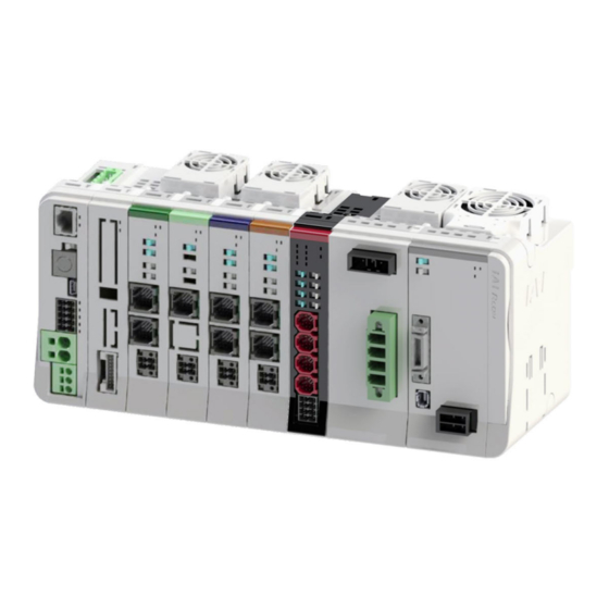
Page 108: Gateway Unit And Accessories
The following table shows the product configuration for the standard specification. See the packing list for the details of the enclosed components. In the unlikely case that any model number errors or missing parts come to light, contact your local IAI distributor. Part name... -
Page 109: Part Names/Functions And External Dimensions
3.4 Part Names/Functions and External Dimensions 3.4 Part Names/Functions and External Dimensions Part names RCON-GW A3-6 ME0384-4A... - Page 110 3.4 Part Names/Functions and External Dimensions T RUN LED Ethernet connector SYS LED AUTO/MANU switch Field network connector SIO connector STOP LED USB connector MODE LED System I/O connector C ERR LED Motor power connector STATUS 0 LED Control power connector STATUS 1 LED Front Connector upper part...
-
Page 111: Led Display
3.4 Part Names/Functions and External Dimensions LED display LED for indicating gateway unit status and field network status. Display Panel notation Status Description color Light ON Normal internal bus communication Green T RUN Blinking Waiting for initialization signal Orange Light ON Bus communication error generated Normal operation Green... -
Page 112: Ethernet Connector
3.4 Part Names/Functions and External Dimensions Ethernet connector A connector for connecting to Ethernet. Equipped only when the Ethernet option is selected. Pin No. Signal name Description Transmit data + side Transmit data - side Receive data + side Not connected Not connected Receive data - side Not connected... -
Page 113: Sio Connector
3.4 Part Names/Functions and External Dimensions SIO connector A connector for connecting the teaching pendant to PC software. PC software can also be connected with a USB. Pin No. Signal name Description Teaching pendant/PC RS-485 differential signal + TP_SD+ side TP_SD- Teaching pendant/PC RS-485 differential signal - side Teaching pendant 5 V output... -
Page 114: Usb Connector
It is a connector to be connected to the PC software or gateway parameter configuration tool. For use, it is necessary to install the USB connection driver for RCON. For how to install the driver, refer to “Startup Section, Chapter 4, 4.1 [Installing USB Connection Driver for RCON] (page B4-14)”. -
Page 115: System I/O Connector
3.4 Part Names/Functions and External Dimensions System I/O connector External AUTO/MANU switching input, STOP input, PSA-24 serial communication line equipped. Note that the following pin No. are short-circuited at shipment. (Pins #1 and #6, pins #2 and #7, pins #3 and #8) Cable connector name: DFMC1.5/5-ST-3.5 (Phoenix Contact) Pin No. -
Page 116: Motor Power Connector
3.4 Part Names/Functions and External Dimensions Motor power connector Motor power +24 V supply connector. Supplies power to the motor of the 24V driver unit linked to the gateway unit. Pin No. Signal name Description Motor power +24 V input Motor power connector compatible wire Item Specifications... -
Page 117: Control Power Connector
3.4 Part Names/Functions and External Dimensions Control power connector Control power +24 V and FG connector. Supplies power for the control power of all units linked to the gateway unit and for the actuator brake. Pin No. Signal name Description Frame ground Control power +24 V input Control power connector compatible wire... -
Page 118: Field Network Connector
3.4 Part Names/Functions and External Dimensions Field network connector A connector for connecting to field networks. Field network details are listed in "3.5 Field Network General Specifications (page A3-19)". Connectors A connector for use between units. Two identical connectors are used. The connectors have a floating structure that absorbs connector misalignment due to housing mating or mounting misalignment between connectors. -
Page 119: Terminal Unit
● The terminal unit to be used should differ depending on the cases when the 200V driver unit is not connected and when it is. the terminal unit (RCON-GW-TR) shown in this page is a terminal unit for 24V that is to be used when the 200V driver unit is not to be connected. -
Page 120: External Dimensions
3.4 Part Names/Functions and External Dimensions External dimensions Gateway unit Item Specifications External dimensions W 30 mm × H 115 mm × D 95 mm Mass About 170g External view See figure below 98.8 A3-17 ME0384-4A... - Page 121 3.4 Part Names/Functions and External Dimensions Terminal unit Item Specifications External dimensions W 12.6 mm × H 115 mm × D 95 mm Mass About 48g External view See figure below 12.6 98.8 A3-18 ME0384-4A...
-
Page 122: Field Network General Specifications
3.5 Field Network General Specifications 3.5 Field Network General Specifications CC-Link Cable connector name: MSTB2.5/5-STF-5.08 AU (Phoenix Contact) Pin No. Signal name Description Signal line A Signal line B Digital ground Connects the shield of shielded cables (This connector's 5-pin FG and the control power connector's 1 pin FG are connected internally) Frame ground (This connector's 4-pin SLD and the control power... -
Page 123: Cc-Link Ie Field
3.5 Field Network General Specifications CC-Link IE Field L.ER LINK L.ER LINK Cable/connector specifications: Ethernet ANSI/TIA/EIA-568-B Category 5e or higher, shielded 8P8C modular plug (RJ45) * It is to be prepared by the customer. LED display Panel Display Name Status Description notation color... -
Page 124: Devicenet
3.5 Field Network General Specifications DeviceNet Cable connector name: MSTB2.5/5-STF-5.08 AU M (Phoenix Contact) Pin No. Pin color scheme Description Black Power supply cable - side Blue Signal data Low side - Shield White Signal data High side Power supply cable + side LED display Panel Display... -
Page 125: Ethercat
3.5 Field Network General Specifications EtherCAT Cable/connector specifications: Ethernet ANSI/TIA/EIA-568-B Category 5 or higher, shielded 8P8C modular plug (RJ45) * It is to be prepared by the customer. LED display Panel Display Name Status Description notation color Light ON Signal component (module) error Configuration information (settings) Blinking error... -
Page 126: Ethernet/Ip
3.5 Field Network General Specifications EtherNet/IP Cable/connector specifications: Ethernet ANSI/TIA/EIA-568-B Category 5 or higher, shielded 8P8C modular plug (RJ45) * It is to be prepared by the customer. LED display Panel Display Name Status Description notation color Light ON Normal operation Green No configuration information, Blinking... -
Page 127: Profibus-Dp
3.5 Field Network General Specifications PROFIBUS-DP Cable side connector name: 9-pin D sub connector (male) * It is to be prepared by the customer. Pin No. Signal name Description Not connected Not connected B-Line Signal line B (RS-485) Transmission request 0 V (isolated) +5 V +5 V output (isolated) -
Page 128: Profinet Io
3.5 Field Network General Specifications PROFINET IO Cable/connector specifications: Ethernet ANSI/TIA/EIA-568-B Category 5 or higher, shielded 8P8C modular plug (RJ45) * It is to be prepared by the customer. LED display Panel Display Name Status Description notation color Light ON Normal communication Blinking Network being diagnosed... -
Page 129: Operation Function List
3.6 Operation Function List 3.6 Operation Function List Field network control operation mode The field network control operation mode can be selected from the following control modes. (except when EC connection unit is connected) Data required for operation (target position, speed, acceleration, push current value, etc.) are written by a connected PLC or other host controller into the specified addresses. -
Page 130: List Of Functions By Operation Mode
3.6 Operation Function List List of functions by operation mode Direct numerical Simple direct Positioner 1 Positioner 2 Positioner 3 Positioner 5 control mode mode mode mode mode mode Number of Unlimited Unlimited 128 points 128 points 128 points 16 points positioning points Home return motion ○... - Page 131 3.6 Operation Function List Note 1: The number of settable position data is 128 points at the maximum. Note 2: This function is limited to the AC servo motor specification. Note 3: It is a feature dedicated for the pulse motor type. Note 4: DD motor is 0.001 degree (0.01 degree for positioner 5 mode only).
-
Page 132: Operation Of Elecylinder
EC connection unit. [Image of Connection] Connection between PLC and ELECYLINDER (1) Input a movement signal (forward or backward) from PLC to RCON (EC connection unit). (2) Input the movement signal from RCON (EC connection unit) to each unit of ELECYLINDER. -
Page 133: Address Configuration
3.7 Address Configuration 3.7 Address Configuration The RCON address configuration is the same for all driver units regardless of field network type. The addresses occupied by the network consist of eight words of the fixed domains, data domains that vary depending on the operation mode and number of axes and the data domains for the EC connection unit. - Page 134 3.7 Address Configuration (2) Direct numerical control mode data region configuration PLC output ⇒ each axis input Each axis output ⇒ PLC input High byte Low byte Word count High byte Low byte Word count Specified position data (L) Present position data (L)) Specified position data (H)) Present position data (H)) Specified positioning width (L))
-
Page 135: Overall Address Configuration Example
3.7 Address Configuration Overall address configuration example Here shows an example for the overall address configuration when four-word mode axes (Simple Direct / Positioner 1) are connected for 12 axes, eight-word mode axes (Direct Indication) for two axes are connected, and also the overall address configuration when two- word mode axes (Positioner 2 / Positioner 5) for 12 axes and one unit of the EC connection unit are connected. - Page 136 ■ CC-Link overall address configuration example (direct numerical control mode + simple direct mode/positioner 1 mode) shows direct numerical control mode connection for 2 axes and simple direct or positioner 1 mode connection for 12 axes. PLC output ⇒ RCON RCON ⇒ PLC input Output register...
- Page 137 *3 The EC connection unit occupies domains and axis numbers for four axes (one word) even though not all of four axes are connected. The axis numbers for the EC connection unit should be assigned from after axes connected to driver units (RCON-PC/AC/DC/PC/SC) and SCON extension unit. A3-34 ME0384-4A...
- Page 138 ■ CC-Link IE Field overall address configuration example (direct numerical control mode + simple direct mode/positioner 1 mode) shows direct numerical control mode connection for 2 axes and simple direct or positioner 1 mode connection for 12 axes. PLC output ⇒ RCON RCON ⇒ PLC input Output register...
- Page 139 *1 The EC connection unit occupies domains and axis numbers for four axes (one word) even though not all of four axes are connected. The axis numbers for the EC connection unit should be assigned from after axes connected to driver units (RCON-PC/AC/DC/PC/SC) and SCON extension unit. A3-36 ME0384-4A...
- Page 140 ■ DeviceNet overall address configuration example (direct numerical control mode + simple direct mode/positioner 1 mode) Shows direct numerical control mode connection for 2 axes and simple direct or positioner 1 mode connection for 12 axes. PLC output ⇒ RCON RCON ⇒ PLC input Relative CH High byte...
- Page 141 *1 The EC connection unit occupies domains and axis numbers for four axes (one word) even though not all of four axes are connected. The axis numbers for the EC connection unit should be assigned from after axes connected to driver units (RCON-PC/AC/DC/PC/SC) and SCON extension unit. A3-38 ME0384-4A...
- Page 142 ■ Overall address configuration example (direct numerical control mode + simple direct mode/positioner 1 mode) Shows direct numerical control mode connection for 2 axes and simple direct or positioner 1 mode connection for 12 axes. PLC output ⇒ RCON RCON ⇒ PLC input Relative byte High byte...
- Page 143 *1 The EC connection unit occupies domains and axis numbers for four axes (one word) even though not all of four axes are connected. The axis numbers for the EC connection unit should be assigned from after axes connected to driver units (RCON-PC/AC/DC/PC/SC) and SCON extension unit. A3-40 ME0384-4A...
- Page 144 ■ PROFINET-IO overall address configuration example (direct numerical control mode + simple direct mode/positioner 1 mode) Shows direct numerical control mode connection for 2 axes and simple direct or positioner 1 mode connection for 12 axes. PLC output ⇒ RCON RCON ⇒ PLC input 4-word High byte...
- Page 145 *1 The EC connection unit occupies domains and axis numbers for four axes (one word) even though not all of four axes are connected. The axis numbers for the EC connection unit should be assigned from after axes connected to driver units (RCON-PC/AC/DC/PC/SC) and SCON extension unit. A3-42 ME0384-4A...
-
Page 146: Gateway Control/Status Signals
3.7 Address Configuration Gateway control/status signals The first 2 words for each I/O in the gateway unit address configuration are signals for controlling and monitoring the status of the gateway unit. PLC output Address CC-Link, DeviceNet PROFIBUS-DP, PROFINET-IO CC-Link IE EtherNet/IP, Field EtherCAT... - Page 147 3.7 Address Configuration I/O signal list Symbol Signal type Content name PLC control output is enabled when ON ("1") (PLC output is reflected on controller unit) and disabled when OFF ("0"). Control * It should be used only for control of driver units signal 0 14-0 -...
-
Page 148: Power Supply Unit (Psa-24) Status Signal
Eight words of input and output from the top address of the gateway unit are the fixed domains. Six words in these domains should be assigned as the power supply unit status signal domains and the condition of the IAI 24V DC power supply unit PSA-24 can be checked. (1) Address configuration Request command region and response command region comprise 6 words for each I/O. - Page 149 3.7 Address Configuration (3) For PROFIBUS-DP, EtherNet/IP, and EtherCAT PLC output ⇒ gateway ⇒ each axis input Each axis output ⇒ gateway ⇒ PLC input Byte Address b15 High byte b8 b7 Low byte b0 b15 High byte b8 b7 Low byte b0 +4/+5 Not available Power supply unit status signal 0...
- Page 150 3.7 Address Configuration I/O signal list Symbol Signal type Content name When communication between the gateway unit and the power supply unit is solidly established, it turns ON when the gateway unit recognizes it as enabled. b14 ~ 11 - Not available OPMV ON when a reading error occurs in monitored data.
-
Page 151: Position Table
3.7 Address Configuration Position table Each driver unit can operate in 6 types of modes, direct numerical control mode, simple direct mode, positioner 1~3 and 5 modes, depending on the gateway unit. Simple direct mode and positioner mode require the creation of a position table in advance, using a teaching tool, in order to perform positioning. - Page 152 3.7 Address Configuration (1) No. Displays the position data No. Caution ● Do not use position No. 0 if the position has play. ● Even if not at Position No. 0 at the first servo ON after power ON, the complete position number output will be 0 and the status will be the same as when positioning to Position No.
- Page 153 3.7 Address Configuration (4) Acceleration/deceleration [G] Input the acceleration/deceleration rate at which the actuator is to travel. Use a value within the rated range. Take care, as it is possible to input a number larger that the catalog rated value. Reduce the number if the object to be conveyed vibrates during acceleration/deceleration, causing problems.
- Page 154 3.7 Address Configuration (5) Push [%] Select "positioning" or "push-motion operation". The factory default setting is 0. : Normal positioning operation Non-0 : Displays the current limit value. Setting this will configure push-motion operation mode. Caution ● Changing the push speed may result in a force different from the original push force. ●...
- Page 155 3.7 Address Configuration (7) Positioning width [mm] Handling of set value differs between "positioning" and "push-motion operation". [Positioning operation] Defines how far before the target position the positioning complete signal should turn ON. Even if the positioning complete turns ON, the actuator will continue to move to the target position.
- Page 156 3.7 Address Configuration [Push-motion Operation] Defines the maximum travel amount using push-motion operation from the target position. Considering the mechanical variation of the workpieces, set the positioning width so as not to complete positioning before pressing against the workpiece. When pushing a workpiece, the positioning complete signal turns ON when it determines the pushing operation is complete.
- Page 157 3.7 Address Configuration For rotary actuator in index mode 0° 0° 315° 315° 70° 70° Set value Set value Zone setting + side : 70° Zone setting + side : 315° Zone setting – side : 315° Zone setting – side : 70° (9) Acceleration/deceleration mode Defines acceleration/deceleration pattern characteristics.
- Page 158 3.7 Address Configuration [S-motion] When accelerating, a curve which starts gently then sharply increases partway through is drawn. This should be used when fast tact time is required so high acceleration/deceleration is wanted, yet a gradual start and stop are required. Speed Time The degree of S-motion ratio setting is set with parameter No.
- Page 159 3.7 Address Configuration [First-order delay filter] This draws a more gentle acceleration/deceleration curve compared to trapezoidal patterns. The shock at acceleration/deceleration is relieved, but the cycle time becomes longer. Use for applications where minor vibrations to the workpiece during acceleration/deceleration are to be avoided.
- Page 160 3.7 Address Configuration (11) Transported load/Gain set This item has different functions depending on motor specifications. Motor specification Function Stepper motor specification Transported load Gain s e t Servo motor specification Stepper motor specification function only [Transported load] Registers four types of load weight with the teaching tool and registers which of them to use by number (0 to 3).
- Page 161 3.7 Address Configuration Parameters configured in 1 set are as follows. Servo gain number (position gain) Positional feedforward gain Velocity loop proportional gain Velocity loop integral gain Torque filter constant Current control band number Set the gain corresponding to the position No.
- Page 162 3.7 Address Configuration (12) Stop mode The servo can be turned OFF automatically at a fixed time after completion of positioning, for power saving. Time setting is performed with parameter No. 36 to 38 Automatic servo OFF delay time 1 to 3, enabling three time options to be selected.
- Page 163 3.7 Address Configuration [Full servo control method] Holding current can be reduced by using servo control with stepper motors. While the degree of reduction varies depending on the actuator model and load conditions, the holding current drops to about 1/2 to 1/4. No position deviation will occur as the system maintains the servo ON status.
- Page 164 3.7 Address Configuration (14) Drive torque limit [%] / Push speed [mm/s] The expansion function can be switched by setting parameter No. 191 "Position data expansion function setting". Parameter No.191 Available expansion set value functions Not displayed (disabled) Drive torque limit Push speed Drive torque limit : Sets the travel current limit value during position travel.
- Page 165 3.7 Address Configuration (15) Connection No. After completing travel, this sets the position No. to continue traveling. If "wait time" is not set, this function will be disabled. This function is subject to the following precautions. Be sure to check before use. (1) AUTO/MANU mode ■...
- Page 166 3.7 Address Configuration (16) Wait time [s] After completing travel, this sets the standby time until the next position No. operation starts. Enabled only when "Connection No." is set. This function can only be enabled in AUTO mode. When performing continuous operation with PC software, use the easy programming function.
-
Page 167: Direct Numerical Control Mode Assignment
3.7 Address Configuration Direct numerical control mode assignment Assigning the direct numerical control mode is as follows. Set the current limit value in push-motion, acceleration/deceleration and speed within the range of the applicable actuator specifications, and set the target position data within the software stroke range. - Page 168 3.7 Address Configuration PLC input = Axis status signal Address CC-Link, DeviceNet 1 word = 16 bits CC-Link IE b15 b14 b13 b12 b11 b10 b9 b8 b7 b6 b5 b4 b3 b2 b1 b0 Field (High byte) n + 0 n + 0 (Low byte) Present position data (signed integer)
- Page 169 3.7 Address Configuration [I/O Signal List] Direct numerical control mode (ON = corresponding bit is "1", OFF = corresponding bit is "0") Signal Signal type Content Details name 32-bit signed integer (unit: 0.01 mm; 0.001° for DD motor). Ex) For +25.40 mm, specify as 2540. ●...
- Page 170 3.8 [7] turned OFF midway, it will run until completion] Note 1: When command speed setting = 0: operates at the value of RCON parameter No. 47 "PIO Jog velocity 2". When command speed setting ≠ 0: operates at the command speed set value.
- Page 171 3.7 Address Configuration [I/O Signal List] Direct numerical control mode (ON = corresponding bit is "1", OFF = corresponding bit is "0") Signal Signal type Content Details name Present position data is output in 32-bit signed integer (unit: 0.01mm and 0.001deg for DD motor). Present 32-bit Ex) For +25.4 mm, it will be 2540.
- Page 172 3.7 Address Configuration [I/O Signal List] Direct numerical control mode (ON = corresponding bit is "1", OFF = corresponding bit is "0") Signal Signal type Content Details name Operation ready 3.8 [5] [ON: Operation ready (Servo ON)] Alarm 3.8 [3] [ON: Alarm generated, OFF: No alarm] Traveling MOVE...
-
Page 173: Simple Direct Mode Assignment
3.7 Address Configuration Simple direct mode assignment Assigning the simple direct mode is as follows. PLC output = Axis control signal Address CC-Link, DeviceNet 1 word = 16 bits CC-Link IE b15 b14 b13 b12 b11 b10 b9 b8 b7 b6 b5 b4 b3 b2 b1 b0 Field (High byte) n + 0... - Page 174 [OFF: Use RCON parameter No. 26 "Jog Control JVEL velocity" and No. 48 "Inching set value" 3.8 [11] signal ON : Use RCON parameter No. 47 "Jog velocity 2" and No. 49 "Inching 2 set value"] Jog/Inching switching JISL 3.8 [12] [ON: Inching, OFF: Jog] Servo ON 3.8 [5]...
- Page 175 3.7 Address Configuration [I/O Signal List] Simple direct mode (ON = corresponding bit is "1", OFF = corresponding bit is "0") Signal type Signal name Content Details 32-bit signed integer (unit: 0.01 mm; 0.001° for DD motor). Ex) For +25.40 mm, outputs as 2540. Present 32-bit ●...
- Page 176 3.7 Address Configuration [I/O Signal List] Simple direct mode (ON = corresponding bit is "1", OFF = corresponding bit is "0") Signal type Signal name Content Details Home return complete HEND [ON: Maintaining home after home return 3.8 [6] complete] Status Positioning complete signal...
-
Page 177: Positioner 1 Mode Assignment
3.7 Address Configuration Positioner 1 mode assignment Assigning the positioner 1 mode is as follows. PLC output = Axis control signal Address CC-Link, DeviceNet 1 word = 16 bits CC-Link IE b15 b14 b13 b12 b11 b10 b9 b8 b7 b6 b5 b4 b3 b2 b1 b0 Field (High byte) n + 0... - Page 178 [OFF: Use RCON parameter No. 26 Jog velocity and No. 48 Inching set Control JVEL value 3.8 [11] signal ON : Use RCON parameter No. 47 Jog velocity 2 and No. 49 Inching 2 set value] Jog/Inching switching JISL 3.8 [12] [ON: Inching, OFF: Jog] Servo ON 3.8 [5]...
- Page 179 3.7 Address Configuration [I/O Signal List] Positioner 1/2 mode (ON = corresponding bit is "1", OFF = corresponding bit is "0") Signal type Signal name Content Details 32-bit signed integer (unit: 0.01 mm; 0.001° for DD motor). Ex) For +25.40 mm, outputs as 2540. Present 32-bit ●...
-
Page 180: Positioner 2 Mode Assignment
3.7 Address Configuration Positioner 2 mode assignment Assigning the positioner 2 mode is as follows. PLC output = Axis control signal Address CC-Link, DeviceNet 1 word = 16 bits CC-Link IE b15 b14 b13 b12 b11 b10 b9 b8 b7 b6 b5 b4 b3 b2 b1 b0 Field (High byte) n + 0... -
Page 181: Positioner 3 Mode Assignment
3.7 Address Configuration Positioner 3 mode assignment Assigning the positioner 3 mode is as follows. PLC output = Axis control signal Address CC-Link, DeviceNet 1 word = 16 bits CC-Link IE b15 b14 b13 b12 b11 b10 b9 b8 b7 b6 b5 b4 b3 b2 b1 b0 Field (High byte) n + 0... - Page 182 3.7 Address Configuration [I/O Signal List] Positioner 3 mode (ON = corresponding bit is "1", OFF = corresponding bit is "0") Signal type Signal name Content Details Forced brake release BKRL 3.8 [15] [ON: forced brake, OFF: brake enabled] - Not available -...
- Page 183 3.7 Address Configuration [I/O Signal List] Positioner 3 mode (ON = corresponding bit is "1", OFF = corresponding bit is "0") Signal type Signal name Content Details Emergency stop status EMGS 3.8 [2] [ON: Emergency stop status] Zone output monitor 1 [ON : Present position is within the setting ZONE1 range of zone 1,...
-
Page 184: Positioner 5 Mode Assignment
3.7 Address Configuration Positioner 5 mode assignment Assigning the positioner 5 mode is as follows. PLC output = Axis control signal Address CC-Link, DeviceNet 1 word = 16 bits CC-Link IE b15 b14 b13 b12 b11 b10 b9 b8 b7 b6 b5 b4 b3 b2 b1 b0 Field (High byte) n + 0... - Page 185 [OFF: Use RCON parameter No. 26 Jog velocity and No. 48 Inching set Control JVEL value 3.8 [11] signal ON : Use RCON parameter No. 47 Jog velocity 2 and No. 49 Inching 2 set value] Jog/Inching switching JISL 3.8 [12] [ON: Inching, OFF: Jog] Servo ON 3.8 [5]...
- Page 186 3.7 Address Configuration [I/O Signal List] Positioner 5 mode (ON = corresponding bit is "1", OFF = corresponding bit is "0") Signal type Signal name Content Details 16-bit signed integer (unit: 0.1 mm; 0.01° for DD motor). Ex) For +25.40 mm, outputs as 254. Present ●...
-
Page 187: Elecylinder Position Table
3.7 Address Configuration ELECYLINDER Position Table The stop position and operating condition settings are established in ELECYLINDER at the delivery. The stop position and the operation conditions can be adjusted with a teaching tool in the simple data setting window. Reference PC software operating method PC software (RCM-101-*-*) manual (ME0155) - Page 188 3.7 Address Configuration (1) Backward End / Forward End [mm] It is the coordinate values for positioning. Input values from the home position. Registration is available in 0.01mm unit. (2) Acceleration / Velocity / Deceleration ● Acceleration [% or G] Acceleration at the start of operation should be set in a value from 1 to 100%.
- Page 189 3.7 Address Configuration (3) Pressing / Pressing Start Point / Pressing Force ● Pressing Selection can be made from “Positioning Operation” and “Pressing Operation”. When there is a check mark at “Pressing”, it should perform the pressing operation. ● Pressing Start Point [mm] *Displayed only in pressing operation It is the position to start the pressing operation.
-
Page 190: Assignment Of Ec Connection Unit
3.7 Address Configuration Assignment of EC Connection Unit The assignment of the EC connection unit should be as shown below. The EC connection unit occupies domains for four axes (one word) even though not all of four axes are connected. PLC output = Axis control signal Address 1 word = 16 bits... - Page 191 3.7 Address Configuration [I/O Signal List] EC Connection Unit (ON = corresponding bit is "1", OFF = corresponding bit is "0") Signal type Signal name Content Details - Not available - Alarm Cancel Page [Alarm cancelled with on] A3-114 Drive Forward [Drives forward with on (drives forward Page after home-return operation when home...
- Page 192 3.7 Address Configuration [I/O Signal List] EC Connection Unit (ON = corresponding bit is "1", OFF = corresponding bit is "0") Signal type Signal name Content Details Operation Ready Page E3RD [On: Operation ready (servo on)] A3-116 Alarm (break contact) Page *ALM [ON:No alarm、OFF:Alarm generated]...
-
Page 193: I/O Signals
3.8 I/O Signals 3.8 I/O Signals Timing of I/O signals In order to operate the actuator with a PLC sequence program, various control signals are turned ON; the maximum response time until their response (status) signals return to the PLC is expressed with the following formula. -
Page 194: Function Of I/O Signals
3.8 I/O Signals Function of I/O signals I/O signals are prepared for each axis No. ON means that the corresponding bit is "1" and OFF means the corresponding bit is "0". Refer to "Features of Input and Output Signals for EC Connection Unit (Pg. A3-114)" for the EC connection unit. - Page 195 When the SON signal is turned OFF while the actuator is in operation, the actuator stops and the servo turns OFF. For actuator with brake, the brake will activate. Servo ON command signal (PLC → RCON) Servo ON status signal (RCON → PLC) Positioning complete signal...
- Page 196 ON. The HEND signal will stay ON unless the home is lost. During home return motion, the positioning complete signal PEND turns OFF and the moving signal MOVE turns ON. HOME (PLC → RCON) HEND (RCON → PLC) PEND (RCON →...
- Page 197 3.8 I/O Signals Unless indicated as home reverse specification (option), the direction of home return for the linear axis is on the motor side, the rotary axis is on the counterclockwise side, and the gripper is on the outside (open side). For details, refer to "Actuator Coordinate System (page Intro-18)".
- Page 198 3.8 I/O Signals (2) Home return operation of rotary actuator [330° rotation specification] Operation range (330 degrees) Home (1) When home return is commanded, the rotary part rotates in the CCW (counterclockwise) direction as seen from the load side. The speed is 20 deg/s. (2) Detects mechanical stopper.
- Page 199 3.8 I/O Signals [Multi-rotation Specification] Home (12) (Forward rotation side swivel end) (11) (Home side) Offset travel distance (10) Rotary axis Offset reference position (Center of (6), (7), (9) and (10)) (Home reverse side) Home sensor detection range (1) When home return is commanded, the rotary part rotates in the CCW (counterclockwise) direction as seen from the load side.
- Page 200 3.8 I/O Signals (3) Home return operation of gripper Finger attachment (Note) Finger attachment (Note) (Note) The finger attachment is not an accessory for the actuator. It is to be prepared by the customer. (1) The unit travels toward the mechanical end (outside) at the home return speed. (2) The unit reverses at the mechanical end and stops at the home position.
- Page 201 3.8 I/O Signals [7] Positioning start (CSTR) PLC output signal Traveling (MOVE) PLC input signal Positioning complete (PEND) PLC input signal Operation mode Direct numerical control Simple direct Positioner 1 Positioner 2 Positioner 3 Positioner 5 ○: Y ○ ○ ○...
- Page 202 3.8 I/O Signals · · T1 ≥ 0 ms Turn OFF by turning PEND OFF. Start signal CSTR (PLC → RCON) ON when entering the positioning width range. (Note 1) PEND (RCON → PLC) Moving signal MOVE (RCON → PLC) Note 1: The MOVE signal turns ON simultaneously as PEND signal is turned OFF, and it turns OFF when command from the controller to the motor is completed.
- Page 203 3.8 I/O Signals [9] Zone 1 (ZONE1) PLC input signal Zone 2 (ZONE2) PLC input signal Position zone (PZONE) PLC input signal Operation mode Direct numerical control Simple direct Positioner 1 Positioner 2 Positioner 3 Positioner 5 △ ○: Y △...
- Page 204 3.8 I/O Signals (1) Zone signal (ZONE1, ZONE2) Turns ON in any range set in the parameter. Set the zone range in the following parameters. (1) ZONE1 : Parameter No. 1 (zone boundary 1 + side), parameter No. 2 (zone boundary 1 - side) (2) ZONE2 : Parameter No.
- Page 205 3.8 I/O Signals (3) Set value and signal output range The zone output range varies depending on the difference between the set value on the + side and - side of the zone. (1) + side set value > - side set value: zone signal ON within the range of - side set value to + side set value, OFF when out of range (2) + side set value <...
- Page 206 3.8 I/O Signals [10] + Jog (JOG+) PLC output signal - Jog (JOG -) PLC output signal Operation mode Direct numerical control Simple direct Positioner 1 Positioner 2 Positioner 3 Positioner 5 ○: Y ○ ○ ○ ○ × ○ ×: N It is a start command for jog or inching operation.
- Page 207 3.8 I/O Signals (2) Inching (incremental) operation Inching operation is available when the JISL signal is ON. When the jog signal is turned ON once, it travels a fixed distance for the inching distance set in the parameter. When the JOG+ signal is ON, it moves in the home reverse direction, and when the JOG- signal is ON, it moves in the home direction.
- Page 208 3.8 I/O Signals [11] Jog speed / inching distance switching (JVEL) PLC output signal Operation mode Direct numerical control Simple direct Positioner 1 Positioner 2 Positioner 3 Positioner 5 ○: Y ○ ○ ○ ○ × ○ ×: N This is a parameter switching signal that specifies the speed and inching distance during jog and inching (incremental) operation.
- Page 209 3.8 I/O Signals [12] Jog/inching switching (JISL) PLC output signal Operation mode Direct numerical control Simple direct Positioner 1 Positioner 2 Positioner 3 Positioner 5 ○: Y ○ ○ ○ ○ × ○ ×: N It is a switching signal between jog operation and inching (incremental) operation. When JISL signal is OFF : Jog operation When JISL signal is ON : Inching operation If the JISL signal is switched to ON (inching) during jog operation, it decelerates and stops, and...
- Page 210 3.8 I/O Signals [13] Teaching mode command (MODE) PLC output signal Teaching mode signal (MODES) PLC input signal Operation mode Direct numerical control Simple direct Positioner 1 Positioner 2 Positioner 3 Positioner 5 ○: Y × × ○ ○ × ×...
- Page 211 Note 2: If data other than the position data is undefined, the parameter initial value will be written. For details, refer to "Startup Section Chapter 6, 6.1 Parameter (page B6-1)". Teaching mode MODES 20 ms or more (RCON → PLC) Position data import command PWRT (PLC → RCON) Position data import complete WEND (RCON →...
- Page 212 3.8 I/O Signals [15] Forced brake release (BKRL) PLC output signal Operation mode Direct numerical control Simple direct Positioner 1 Positioner 2 Positioner 3 Positioner 5 ○: Y ○ ○ ○ ○ ○ ○ ×: N While the forced brake release signal BKRL is ON, the brake will be released. For an actuator with brake, the brake is automatically controlled by servo ON/OFF.
- Page 213 3.8 I/O Signals [16] Push-motion specification (PUSH) PLC output signal Operation mode Direct numerical control Simple direct Positioner 1 Positioner 2 Positioner 3 Positioner 5 ○: Y ○ × × × × × ×: N Executing a travel command after turning this signal ON will activate push-motion operation. When this signal is OFF, normal positioning operation will be performed.
- Page 214 3.8 I/O Signals [17] Push direction specification (DIR) PLC output signal Operation mode Direct numerical control Simple direct Positioner 1 Positioner 2 Positioner 3 Positioner 5 ○: Y ○ × × × × × ×: N Specifies the direction of push-motion. When this signal is turned OFF, push-motion is performed toward the value obtained by subtracting the positioning width from the target position.
- Page 215 3.8 I/O Signals [20] Incremental specification (INC) PLC output signal Operation mode Direct numerical control Simple direct Positioner 1 Positioner 2 Positioner 3 Positioner 5 ○: Y ○ × × × × × ×: N When this signal is ON, if a travel command is executed, it will travel by the value input in the target position register of the PLC with the present position as a reference.
- Page 216 3.8 I/O Signals Stepper motor specification function only [22] Load output judgment status (LOAD) PLC input signal Operation mode Direct numerical control Simple direct Positioner 1 Positioner 2 Positioner 3 Positioner 5 ○: Y × ○ ○ ○ × × ×: N [1] Pressing operation commanded torque level detection signal It turns on when the actuator gets in the pressing operation range and also in the position...
-
Page 217: Features Of Input And Output Signals For Ec Connection Unit
3.8 I/O Signals Features of Input and Output Signals for EC Connection Unit The input and output signals for the EC connection unit are as shown below. On means the applicable bit is "1" while off means "0". [1] Movement command input backward end/forward end (ST0/ST1) PLC output signal The ST signal function automatically switches depending on whether the unit has completed home return or not. - Page 218 3.8 I/O Signals [2] Alarm clear input (RES) PLC output signal ● When the [RES] signal is turned ON, the currently triggered alarm will be cleared. ● Alarm clear may not be possible depending on the alarm itself. Refer to "Maintenance Section Chapter 2, 2.5 Troubleshooting for ELECYLINDER alarm groups (Page C2-30)"...
- Page 219 3.8 I/O Signals [4] Pressing complete output backward end/forward end (PE0/PE1) PLC input signal ● Turns ON when "pressing complete" is determined during pressing operation. ● Turns OFF if no contact can be made. [5] Alarm output (*ALM) PLC input signal ●...
-
Page 220: Caution When Connecting Ec Connection Unit
● The axis numbers for the EC connection unit should be assigned from after axes connected to driver units (RCON-PC/AC/DC/PC/SC) and SCON extension unit. ● The EC connection unit can be connected for four units at maximum, however, it cannot be connected if the top axis number exceeds 0 to 15 and an alarm should get generated. -
Page 221: Timing Of Basic Operation
Timing of basic operation [Operation preparation] The procedure from turning on the RCON system to the home return command is as follows. (1) Supply the control power and motor power (24 VDC/AC200V). (2) Turn on the STOP signal input to cancel the drive shutoff status and set to conductive status. - Page 222 3.8 I/O Signals Drive-source cutoff status Drive-source cutoff cancel Safety circuit status Control power [Input] (24 VDC) Motor power [Input] (24 VDC/AC200V) (Note 1) Gateway status signal 0 RUN [Output] (Note 2) Gateway status signal 1 LNK* [Output] Servo ON signal (Note 3) SON [Input] (Note 4)
- Page 223 3.8 I/O Signals Note 1: When the power is turned ON, the RCON system starts up. When field network communication between the gateway unit and host device is established, the gateway status signal 0 "RUN" turns ON. After confirming that the "RUN" is ON, begin communication with the gateway unit.
- Page 224 ON the positioning start signal CSTR. The data set in (1) to (5) are read into the RCON at the rising edge of the CSTR signal. (9) After the CSTR signal is turned ON, the PEND signal turns OFF after Tpdf.
- Page 225 3.8 I/O Signals (PLC → RCON) (PLC → RCON) Speed data (PLC → RCON) (PLC → RCON) (PLC → RCON) PUSH (PLC → RCON) Specified push direction (PLC → RCON) Positioning start (13) CSTR (PLC → RCON) (Note 1) Tpdf...
- Page 226 ON the positioning start signal CSTR The data set in (1) and (2) are read into the RCON at the rising edge of the CSTR signal. (4) After the CSTR signal is turned ON, the PEND signal turns OFF after Tpdf.
- Page 227 3.8 I/O Signals Target position data setting (PLC → RCON) (PLC → RCON) 10ms or more Positioning start CSTR (PLC → RCON) (Note 1) PEND (RCON → PLC) Present position (RCON → PLC) Traveling MOVE (RCON → PLC) Actuator travel Note 1 Tpdf : Response time For details of the response time, refer to “Timing of I/O signals (page A3-90)”.
- Page 228 (2) While the positioning complete signal PEND is ON or the moving signal MOVE is OFF, turn ON the positioning start signal CSTR. The data set in (1) are read into the RCON at the rising edge of the CSTR signal. (3) After the CSTR signal is turned ON, the PEND signal turns OFF after Tpdf.
- Page 229 3.8 I/O Signals (PLC → RCON) 10ms or more Positioning start CSTR (PLC → RCON) Tpdf (Note 1) PEND (RCON → PLC) (In positioner 5 mode) Present position (RCON → PLC) Traveling MOVE (RCON → PLC) (RCON → PLC) Actuator...
-
Page 230: Other Basic Operations
3.8 I/O Signals Other basic operations [Push-motion Operation] (1) Basic operation After moving to the set target position as shown below, advance at the set push speed with push motion by the positioning width set as the maximum travel amount. When the pushing force reaches a certain value during push motion, it is judged that pushing is completed and the positioning complete signal PEND becomes "1"... - Page 231 3.8 I/O Signals ■ Push mode specification • For positioner 1~3 and 5 mode and simple direct mode, set a numerical value to something other than 0 in the "Push" column of the position table. (Pushing current limit value) • For direct numerical control mode, set the value to the current limit value area at the time of pushing (8-bit), and set the control signal PUSH (bit 12) to "1"...
- Page 232 3.8 I/O Signals (2) For push-motion contactless Even if it travels the distance set for positioning width, positioning complete signal PEND will not be output if it has not pushed the workpiece (the current of the motor has not reached the current limit value at the time of pushing).
- Page 233 3.8 I/O Signals (4) If push direction is set incorrectly If the push direction is set incorrectly, be careful as it will be displaced by (positioning width x 2) as shown below. Speed Intended operation Actual operation Travel distance Positioning width Positioning width Positioning Actual travel position...
- Page 234 3.8 I/O Signals (6) When SEP is set as push mode The 24V driver unit is capable to change the pressing method to SEP type by setting Parameter No. 181 to "1". (Note) Note: The pressing method for the 200V driver unit is the CON type only. [Push Mode (Parameter No.
- Page 235 3.8 I/O Signals Stepper motor specification function only (7) Pressing operation commanded torque level detection It is a signal dedicated for the high-thrust actuator that possesses the stepper motor specification (PCF Type). It should be used as a reference for output when it is used for an actuator other than the motor specification high-thrust type.
- Page 236 3.8 I/O Signals [Pausing] Deceleration to a stop occurs when the pause command signal STP is set to "1" (ON) during actuator operation and the remaining travel distance is suspended. If the STP signal is set to "0" (OFF) again, movement over the remaining travel distance is resumed. Command position Positioning start (CSTR)
- Page 237 3.8 I/O Signals [Speed changes while traveling] Multiple speed control is possible with one operation. While traveling, you can slow down or speed up from a given point. However, position data is required every time the speed changes. Position 1 Position 2 Position 1 Position 2...
- Page 238 3.8 I/O Signals Caution ● When the positioning start signal CSTR is set to "1" (ON), positioning complete signal PEND changes to "0" (OFF) and the moving signal MOVE changes to "1" (ON). Set the start signal CSTR to "1" (ON); after confirming that the PEND signal is "0" (OFF), set the CSTR signal back to "0"...
- Page 239 3.8 I/O Signals [Operation at Different Acceleration/Deceleration Speeds] (1) In positioner 1~3 and 5 mode and simple direct mode Acceleration and deceleration can be set separately in the position table. (2) In direct numerical control mode In this mode, acceleration and deceleration cannot be set separately. Acceleration/deceleration can be set together.
- Page 240 3.8 I/O Signals [Operation by Specifying Relative Coordinates] Relative coordinates for the target position of the position table can also be specified, allowing use for equidistant positioning operations. (1) Example for operation in positioner 1~3 and 5 mode Here is an example for positioning with 50 mm pitch starting from position No. 1. Create a position table like the one below.
- Page 241 3.8 I/O Signals Command position Position 1 Position 2 Positioning start (CSTR) Positioning complete (PEND) Completed position Position 1 Position 2 Position 2 Traveling (MOVE) Zone signal (PZONE) Actuator travel Time Distance from home * Consider the scan time of the host controller, so that T1 ≥ 0 ms. [Description of Operation] (1) Positioning to position 1 (100.00 mm) is carried out (2) When positioning to position 1 is completed, positioning complete signal PEND changes to...
- Page 242 3.8 I/O Signals (2) Precautions for positioning operation When selecting and inputting position No. of the relative coordinates during positioning operation and performing start input, it travels to the first position plus the amount of relative travel. (If the amount of relative travel is negative, it moves to the position subtracted from the first position.) Example: If start input of position 2 is performed during travel to position 1, it will go to a position 40mm from home.
- Page 243 3.8 I/O Signals (3) Precautions for push-motion operation When selecting and inputting position No. (pushing designation) of the relative coordinates while traveling in push mode, it travels to the input position plus the relative travel amount. Therefore, the end point position is not fixed. Example: If start input of position 2 is performed during travel to position 1 in push mode, it will go to a position 10mm from the input position.
- Page 244 3.8 I/O Signals [Shortcut control of multi-rotation specification rotary actuator] (1) Setting shortcut selection Shortcut selection can be set to enabled/disabled in parameter No. 80 "Rotary axis shortcut select". When shortcut selection is enabled, it is also possible to operate only in the same direction.
- Page 245 3.8 I/O Signals (2) Infinite rotation control When shortcut selection is enabled for continuous operation in the same direction, it is possible to perform continuous rotation in the same manner as a motor. Proceed as follows to perform continuous operation. [Operation examples] This example shows 2 rotations, finally stopping at position No.
-
Page 246: Basic Operations Of Elecylinder
3.8 I/O Signals Basic Operations of ELECYLINDER [Home return operation/positioning operation] Turning the [ST0] signal ON when home return is not complete will first trigger home return operation. After a momentary stop at the home position, it will then move to the backward end. As well, when the [ST1] signal is turned ON, the unit will move to the forward end after home return operation. - Page 247 3.8 I/O Signals This shows the PLC timing chart for operating the ELECYLINDER. The basic process is as follows. Move to forward Move to backward Power ON Home return [Basic timing chart] ELECYLINDER → PLC → input signals to Output Input output signals to PLC ELECYLINDER...
- Page 248 3.8 I/O Signals Turning the ST signal OFF midway through operation will cause a gradual stop. For example, be careful of the following point with a large LS signal detection range. If the sequence is set to turn the ST signal OFF immediately after the LS signal turns ON, the ELECYLINDER may not have reached the forward/backward end.
- Page 249 3.8 I/O Signals The basic time chart is as follows. ST signal PE signal ON → ST signal OFF Not ON PE signal at failure to contact ELECYLINDER movement Pressing Pressing complete Approach operation operation Caution ● The pressing operation speed is 20 mm/s. Refer to an instruction manual of each ELECYLINDER or a catalog for detail.
- Page 250 3.8 I/O Signals The torque (current limit value) configured for [Pressing force] in the Simple Data Setting screen judges completion of pressing operation. When the ELECYLINDER is performing pressing operation, satisfying the following conditions will produce a judgment of pressing complete, turning ON the PE signal. (Accumulated time in which current has reached pressing value [%]) - (Accumulated time in which current is less than pressing value [%]) ≥...
-
Page 251: Precautions For Rotary Type
3.8 I/O Signals Precautions for Rotary Type (1) Homing direction Home position is the counter-clockwise moving end of the output shaft. The multi-rotation specification includes a reverse-rotation specification. For reverse-rotation specification, the homing direction is clockwise. Caution ● If the homing direction is changed by changing the parameter after delivery, the homing direction will be reversed. - Page 252 3.8 I/O Signals (3) Angular velocity and acceleration/deceleration command Angular velocity (deg/s) is the command value for rotation angle. Acceleration/deceleration is specified as "G" in the program. Rated angular acceleration/deceleration: 0.3G = 2,940 deg/s (4) Home return motion [330° rotation specification] Operation range (330 degrees) Home (1) When home return is commanded, the rotary part rotates in the CCW (counterclockwise)
- Page 253 3.8 I/O Signals [Multi-rotation Specification] Home (12) (Forward rotation side swivel end) (11) (Home side) Offset travel distance (10) Rotary axis Offset reference position (Center of (6), (7), (9) and (10)) (Home reverse side) Home sensor detection range (1) When home return is commanded, the rotary part rotates in the CCW (counterclockwise) direction as seen from the load side.
-
Page 254: Precautions For Gripper Type
3.8 I/O Signals Precautions for Gripper Type (1) Finger part operation [Definition of position] Home is the position where the fingers are open. Position command is the travel distance from home position of this single finger to the closed side. Therefore, the maximum command value is 5mm for RCP2-GRS type, or 7mm for RCP2-GRM type. - Page 255 3.8 I/O Signals (2) Removing gripped workpieces This gripper is structured to maintain its gripping force by self-locking the workpiece even during servo OFF or controller power shut-off. When removal of a gripped workpiece is necessary during power shut-off, turn the opening/closing screw or remove the finger attachment on one side to remove the workpiece.
-
Page 256: Gateway Parameter Configuration Tool
Main screen (initial state) Caution ● If the actual number of connected axes of the RCON system does not match the number of axes set and transferred in the gateway parameter configuration tool, the PC software cannot be connected. -
Page 257: Menu Descriptions
3.9 Gateway Parameter Configuration Tool Menu descriptions [File menu] On the main screen, click on the file menu on the upper left to display the menu items as shown above. • New file : Creates a new network parameter and operation mode parameter. •... - Page 258 3.9 Gateway Parameter Configuration Tool [Monitor menu] Click the "Monitor" menu in the upper left of the main screen to display the monitor menu items. (Note) "Monitor" cannot be selected before reading in the parameters. • I/O data : Displays the communication contents between the host PLC and gateway unit.
-
Page 259: Special Parameter Setting Function Descriptions
3.9 Gateway Parameter Configuration Tool Special parameter setting function descriptions [GW parameters] • ERR_T/C occur latch : Selects whether to continue the error in recoverable state after ERRT and ERRC occur. • SERVO-OFF in ERR_C : Selects whether to turn the servo of the connected axis OFF when ERRC is generated. - Page 260 (four axes) should get misaligned. • Number of power supply units connected : Sets the number of IAI power supply units (Model: PSA-24) that are connected to the gateway unit. Up to 5 units can be connected.
- Page 261 3.9 Gateway Parameter Configuration Tool Item Description This power supply can vary the output voltage according to the load. Output voltage The output voltage monitoring value changes, but this is not abnormal. Control power supply voltage inside the power supply unit. As with the Voltage of auxiliary output voltage, it changes according to the load on the output voltage winding...
- Page 262 3.9 Gateway Parameter Configuration Tool Byte swap : Swaps the master and slave bytes of transmitted/received data. Set according to the master to be connected as necessary. ●: ON Input ○: OFF register ON/OFF data PLC: RWwnn ON/OFF data Output register ON/OFF data...
- Page 263 [Option Unit Parameter] • RCON-EC JOG switch : Select whether to activate/inactivate the jog switch on the EC connection unit (RCON-EC). The setting to activate/inactivate should be reflected to all the units of the EC connection unit that are connected to the gateway unit.
- Page 264 3.9 Gateway Parameter Configuration Tool [Time setting] When PC-Time is selected, the current time of the PC is acquired and set to the gateway unit. Once manual setting is selected, set any time set in the time editing on the screen to the gateway unit.
-
Page 265: Explanations Of Monitoring Menu Features
3.9 Gateway Parameter Configuration Tool Explanations of Monitoring Menu Features [I/O data (register monitor)] Data reading cycle Display switch Synchronous scroll The data that the gateway received from the master and transmission data returned to the master are displayed on this register monitor screen. •... - Page 266 3.9 Gateway Parameter Configuration Tool [Diagnostic information] The scan time of the driver unit, the number of communication errors (ERRC, ERRT) and the number of stops (EMG) detected can be counted. When there is an option unit connected, the scan time and the number of communication errors of the option unit should be displayed.
-
Page 267: Operation Mode Setting
3.9 Gateway Parameter Configuration Tool Operation mode setting The operation after main screen reading is as follows. (1) Read For the first connection, the following dialog will be displayed. Press "Yes" to transfer the parameters that match the current configuration. (2) Axis Type Sets the number of axes of the actuator to be controlled (3) Optional units... - Page 268 3.9 Gateway Parameter Configuration Tool (5) Detailed setting display When you press "Detail setting", the following buttons will be displayed. · [Operation mode individual setting] button ((6)) · "Axis number assignment change" button and automatic/manual axis number assignment switching ((7)) (6) Operation mode individual setting When you press "Operation mode individual setting", the "Operation mode individual setting screen"...
-
Page 269: Operation Mode Individual Setting
3.9 Gateway Parameter Configuration Tool Operation mode individual setting The operation for operation mode individual setting is as follows. (1) Axis number assignment confirmation When "Axis number allocation number confirmation" button is pressed, the "Axis number assignment / unit configuration confirmation screen" opens. Note that axis numbers cannot be edited on this screen. -
Page 270: Axis Number Assignment Change
3.9 Gateway Parameter Configuration Tool Axis number assignment change The operation of axis number assignment change is as follows. (1) Hardware configuration (reference information) Displays the driver unit configuration connected to the gateway unit. When creating or editing, if the configuration cannot be read due to a communication error, the following screen will be displayed. -
Page 271: Editing Driver Unit Configuration
3.9 Gateway Parameter Configuration Tool Editing driver unit configuration The driver unit configuration editing method is as follows. Reflect the current driver unit configuration (1) On the "Axis number assignment / Unit configuration confirmation screen", press "Current configuration reflection". (2) The configuration of the actual driver unit will be imported. (3) Confirm the unit configuration and press "Complete". - Page 272 "Automatic", and the 200V driver unit should get assigned to the last of the 24V driver units (RCON-PC/PCF/AC/DC). When SCON-CB is connected using the SCON extension unit (RCON-EXT), the 200V driver unit should be assigned before SCON-CB. Also, the 24V driver units cannot be moved or added after the 200V driver unit.
- Page 273 3.9 Gateway Parameter Configuration Tool [When connecting SCON-CB] When SCON-CB is connected using an extension unit (RCON-EXT), set “Axis No. assignment / unit configuration setting” to “Auto”, and SCON-CB should be assigned to the last of all the driver units.
- Page 274 When the EC connection unit is connected, set the number of EC connection units to be connected in “Option units”. The axis numbers for the EC connection unit should be assigned after each driver unit (RCON- PC/PCF/AC/DC/SC) and SCON-CB. Also, no other unit can be moved or added after the EC connection unit.
- Page 275 3.9 Gateway Parameter Configuration Tool Edit the settings of the specific driver unit (1) On the "Axis number assignment / Unit configuration confirmation screen", press "Editing unit". (2) "Editing unit screen" opens. Select the driver units to be edited and press "Next". A3-172 ME0384-4A...
- Page 276 3.9 Gateway Parameter Configuration Tool (3) "Unit type change screen" opens. Select the unit type from the following 6 types and press "Next". Unit type PC, PCF, AC, DC, SC, SCON, reserved (4) "Axis configuration change screen" opens. First, select the number of axes to be used in the driver unit. Number of axes of selected driver unit Selection item 1 *1...
- Page 277 3.9 Gateway Parameter Configuration Tool (5) Next, set the axis number after adding/deleting. Select from the following selection items and press "Complete". Number of Axes Selection item Axis number setting change results Shift Shifts the axis number of the added drivers from before. When adding Unallocated number Sets unassigned number to the added driver.
- Page 278 3.9 Gateway Parameter Configuration Tool <When Drv1 is deleted from Unit1 and "Shift" is selected> <When Drv1 is deleted from Unit1 and "Keep as reserved unit" is selected> Add the driver unit (1) In "Axis number assignment / Unit configuration confirmation screen", press "Adding unit".
- Page 279 3.9 Gateway Parameter Configuration Tool (2) "Additional location screen" opens. Select the position to which the driver unit is to be added and press "Next". (3) "Adding unit screen" opens. Select the unit type from the following 6 types and select the number of axes, then press "Next".
- Page 280 3.9 Gateway Parameter Configuration Tool (4) "Axis configuration change screen" opens. First, select the number of axes to be used in the driver unit. Selection item Axis number setting change results Unallocated number Sets unassigned number. Shift Shifts the axis number of the added drivers from before. <When the reserved unit is added to Unit1-Unit2 and "Shift"...
- Page 281 3.9 Gateway Parameter Configuration Tool Move the driver unit (1) On the "Axis number assignment / Unit configuration confirmation screen", press "Moving unit". (2) "Moving unit screen" opens. Select the driver unit to be moved and its position, and press "Complete". A3-178 ME0384-4A...
- Page 282 3.9 Gateway Parameter Configuration Tool Delete the driver unit (1) On the "Axis number assignment / Unit configuration confirmation screen", press "Deleting unit". (2) "Deleting unit screen" opens. Select the driver units to be deleted and press "Complete". A3-179 ME0384-4A...
-
Page 283: Actuator Information Management Function
3.10 Actuator Information Management Function 3.10 Actuator Information Management Function Overview IAI actuators have the following 3 types of information management function. This information is saved in the actuator and can be confirmed through the RCON system. [Individual identification information] The actuator's serial number and model information have been written to the actuator at the factory shipment. -
Page 284: Actuators With Information Management Function Supported
3.10 Actuator Information Management Function Actuators with information management function supported Actuators that satisfy the following 2 conditions support the information management function. ● High resolution battery-less absolute encoder compatible model ● Models whose function version supports the information management function [High resolution battery-less absolute encoder compatible model] The following series types are mainly applicable. -
Page 285: Actuator Information Management Function
[Individual identification information] Using the teaching pendant or PC software, you can check the information written on the actuator connected to the RCON system. Serial No., function version, and model number are written at factory shipment. For teaching tool operation, refer to the following instruction manuals. - Page 286 3.10 Actuator Information Management Function [Maintenance Information] In addition to the information saved in the RCON system (total travel count, total travel distance), the actuator maintenance information (travel distance, lubrication time, replacement time, etc.) can be managed. The actuator maintenance information is saved in the actuator.
- Page 287 3.10 Actuator Information Management Function [User memo] Any 124-byte character string (124 1-byte characters, 62 2-byte characters) can be saved. You can confirm, enter and edit using the teaching tool. A3-184 ME0384-4A...
-
Page 288: Parameters For Actuator Information Management Function Setting
3.10 Actuator Information Management Function Parameters for actuator information management function setting Parameters related to this function are as follows. AC servo motor specification and stepper motor specification only [Actuator recognition function (parameter No. 192)] Name Unit Input range Default initial value setting Actuator recognition 0: Disabled -... - Page 289 Specifications Section Chapter 24V Driver Unit EC Connection Unit Overview ··························································· A4-1 How to Read the Model Number ····························· A4-3 How to read the model nameplate ····································· A4-4 Components ······················································· A4-5 Part Names/Functions and External Dimensions ········ A4-7 [24V Driver unit] Part names ···································································...
- Page 290 Connectors ··································································· A4-16 Fan unit ········································································ A4-17 External dimensions (24V Driever unit, Fun unit) ·················· A4-19 [EC Connection Unit] Part names ··································································· A4-21 LED display ··································································· A4-22 Brake release switch ······················································· A4-24 onnectors for EC Connection ············································ A4-25 Drive source shutoff connector ·········································· A4-26 Connectors ···································································...
- Page 291 ME0384-4A...
-
Page 292: Overview
Also, the number of ELECYLINDER available to be connected to one unit of the EC connection unit should be four axes at the maximum. In this section, explains the 24V driver units (RCON-PC/PCF/AC/DC) and the EC connection unit (RCON-EC). Refer to Specification Edition Chapter 5 for the 200V driver unit (RCON-SC). - Page 293 SCON-CB (RCON Connection Type) Model: RCON-ABU-P (for stepper motor) Model: RCON-ABU-A (for AC servo motor) RCP/RCA Note1: The following 200V servo-motor actuators cannot be connected to the 200V driver units. 1) Motor types other than those from 60W to 750W 2) Encoder types other than battery-less absolute, incremental, spurious absolute or index absolute type 3) For 3-Phase 200V ··········...
-
Page 294: How To Read The Model Number
The model codes for the 24V driver unit and EC connection unit are as shown below. 1-axis specification or 2-axis specification can be selected for RCON-PC/AC/DC. There is only one type, one-axis type for RCON-PCF and one type, four-axis type for the EC connection unit. -
Page 295: How To Read The Model Nameplate
(AXI: 1st axis, AXII: 2nd axis) [EC Connection Unit] [Nameplate Location] → Model number → Serial number Caution Mark Type→ ↑ Serial number Mark Explanation of Mark Use IAI specified cables only. Do not touch product when power is ON. Risk of burn. A4-4 ME0384-4A... -
Page 296: Components
The following table shows the product configuration for the standard specification. See the packing list for the details of the enclosed components. In the unlikely case that any model number errors or missing parts come to light, contact your local IAI distributor. [24V Driver Unit]... - Page 297 4.3 Driver Unit and Components [EC Connection Unit] Part name Shape Quantity Remarks Model example: Driver unit RCON-EC Model: DFMC1.5/4-ST-3.5 Drive source shutoff connector * Supplied with EC Connection Unit First Step Guide Safety Guide A4-6 ME0384-4A...
-
Page 298: Part Names/Functions And External Dimensions
4.4 Part Names/Functions and External Dimensions 4.4 Part Names/Functions and External Dimensions [24V Driver Unit] Part names RCON-PC (green) RCON-AC (blue) RCON-DC (brown) A4-7 ME0384-4A... - Page 299 4.4 Part Names/Functions and External Dimensions SYS LED (1st axis) T RUN LED SYS LED (2nd axis) Jog switch (1st axis) Brake switch (1st axis) Jog switch (2nd axis) Brake switch (2nd axis) Fan connector Motor/encoder connector (1st axis) Motor/encoder connector (2nd axis) Drive source shutoff connector...
-
Page 300: Led Display
4.4 Part Names/Functions and External Dimensions LED display Display Panel notation Status Description color Light ON Normal internal bus communication Green Blinking Waiting for initialization signal, initialization communication failed T RUN Orange Light ON Bus communication error generated Light OFF Communication stop Light ON Servo ON... -
Page 301: Jog Switch
● The jog switch is disabled when the communication with the teaching tool is disconnected while the screen in which the actuator can be operated with the teaching tool is opened. ● To enable jog switch operation again, turn the RCON system on again or perform software reset. A4-10... -
Page 302: Brake Release Switch
A connector to connect to the actuator. I indicates the 1st axis, and II indicates the 2nd axis. In RCON, the axis numbers will be automatically allocated from the unit closest to the gateway unit (except for the axis connecting to the EC Connection Unit and the SCON extension unit). - Page 303 4.4 Part Names/Functions and External Dimensions RCON-PC/PCF Driver Unit Pin No. Signal name Description Encoder phase A+ input Brake release - side Motor drive line phase A+ ϕA+ Motor drive line phase A- ϕA- Motor power line Encoder phase A- input...
- Page 304 4.4 Part Names/Functions and External Dimensions RCON-AC Driver Unit Pin No. Signal name Description Encoder phase B+ input Limit switch - side Motor drive line phase U Motor drive line phase W Motor drive line phase V Encoder phase B- input...
- Page 305 4.4 Part Names/Functions and External Dimensions RCON-DC Driver Unit Pin No. Signal name Description Encoder phase B+ input Limit switch - side Motor drive line phase U Motor drive line phase W Motor drive line phase V Encoder phase B- input...
-
Page 306: Drive Source Shutoff Connector
4.4 Part Names/Functions and External Dimensions Drive source shutoff connector Drive-source cutoff input. Drive source can be cut off by individual axes. Cable connector name: DFMC1.5/2-STF-3.5 (Phoenix Contact) Pin No. Signal name Description Motor power output (2nd axis) MPO_II Motor power output (1st axis) MPO_I Motor power input (2nd axis) MPI_II... -
Page 307: Fan Connector
4.4 Part Names/Functions and External Dimensions Fan connector A connector to connect the fan unit. It connects to the fan board connector on the fan unit side. Fan connector Connectors A connector for use between units. Two identical connectors are used. The connectors have a floating structure that absorbs connector misalignment due to housing mating or mounting misalignment between connectors. -
Page 308: Fan Unit
1 fan unit to be used per 2 driver units. The fan rotates when the driver unit internal temperature rises and stops when the temperature falls. Fan unit (Model: RCON-FU) Fan unit Operation without derating is possible without a fan unit at 0-40°C; however, at 40-55°C, actuator operating duty must be reduced by 20% every 5°C. - Page 309 (1) Pull fan unit (2) Adjust the installation orientation of the off upwards RCON system and new fan unit. New Fan Unit Hook the claw of the fan unit to the driver unit as shown in the figure on the right.
-
Page 310: External Dimensions (24V Driever Unit, Fun Unit)
4.4 Part Names/Functions and External Dimensions External dimensions (24V Driever unit, Fun unit) 24V Driver unit (common for RCON-PC/PCF/AC/DC types) Item Specifications External dimensions W22.6 mm × H115 mm × D95 mm Mass About 180g External view See figure below 22.6 7... - Page 311 4.4 Part Names/Functions and External Dimensions Fan unit Item Specifications External dimensions W34.2 mm × H49 mm × D12.5 mm Mass About 16g External view See figure below 18.35 34.2 12.5 A4-20 ME0384-4A...
-
Page 312: [Ec Connection Unit]
T RUN LED backward end LED (1st to 4th Axes) SYS LED Jog switch Brake Release Switch (1st to 4th Axes) (1st to 4th Axes) RCON-EC Drive source shutoff connector Front Connector upper part Connector bottom part Connector Connector DIN tab... -
Page 313: Led Display
4.4 Part Names/Functions and External Dimensions LED display Display Panel notation Status Description color Light ON Normal internal bus communication Green T RUN Blinking Waiting for initialization signal, initialization communication failed Orange Light ON Bus communication error generated Light ON Servo ON Green Blinking... - Page 314 Setting “RCON-EC Jog Switch” in GW Parameter invalid should make the jog switches on all the units of the EC connection unit connected to the gateway inactivated. (It is set to “Valid” in the initial setting.)
-
Page 315: Brake Release Switch
4.4 Part Names/Functions and External Dimensions Brake release switch They are switches to release the brake compulsorily. It comes the switches for 1st, 2nd, 3rd and 4th axes from the top. Should be on NOM side during normal operation. On NOM side, the brake will be released by servo ON and locked by servo OFF. -
Page 316: Onnectors For Ec Connection
SCON extension unit. Axis numbers for four axes should be assigned to the EC connection unit even if ELECYLINDER is not connected to all of four. An axis number that an axis is not connected should not be pulled one number forward. [RCON-EC] Pin No. Signal name... -
Page 317: Drive Source Shutoff Connector
4.4 Part Names/Functions and External Dimensions Drive source shutoff connector Drive-source cutoff input. Drive source can be cut off by individual axes. Cable connector name: DFMC1.5/2-ST-3.5 (Phoenix Contact) Pin No. Signal name Description MPO_3 Motor power output 4th axes MPO_2 Motor power output 3th axes MPO_1 Motor power output 2nd axes... -
Page 318: Connectors
4.4 Part Names/Functions and External Dimensions Connectors A connector for use between units. Two identical connectors are used. The connectors have a floating structure that absorbs connector misalignment due to housing mating or mounting misalignment between connectors. Plug side connector Receptacle connector A4-27 ME0384-4A... -
Page 319: External Dimensions
4.4 Part Names/Functions and External Dimensions External dimensions [EC Connection Unit] Item Specifications External dimensions W22.6 mm × H115 mm × D95 mm Mass About 114g External view See figure below 22.6 98.8 A4-28 ME0384-4A... - Page 320 4.4 Part Names/Functions and External Dimensions A4-29 ME0384-4A...
- Page 321 Specifications Section Chapter 200V Driver Unit 200V Power Supply Unit Overview ··························································· A5-1 How to Read the Model Number ····························· A5-3 How to read the model nameplate ····································· A5-4 Components ······················································· A5-6 Part Names/Functions and External Dimensions ········ A5-8 [200V Driver Unit] Part names ···································································...
- Page 322 Connectors ··································································· A5-13 Fan Unit for 200V Driver Unit ············································ A5-14 External dimensions (200V Driver Unit, Fan Unit for 200V Driver Unit) ·· A5-16 [200V Power Supply Unit] Part names ··································································· A5-18 External Regenerative Resistor Connector ·························· A5-21 200V AC Input Connector ················································ A5-22 Fan connector ·······························································...
- Page 323 ME0384-4A...
-
Page 324: Overview
5.1 Overview 5.1 Overview [200V Driver Unit] The 200V driver unit is a controller dedicated for R Unit. The maximum number of axes available to control with one unit of the driver unit is one axis. The basic features and performances are the same as those for SCON controllers. - Page 325 RCS/ISB, etc. (RCON Connection Type) Model: RCON-ABU-P (for stepper motor) Model: RCON-ABU-A (for AC servo motor) RCP/RCA Note1: The following 200V servo-motor actuators cannot be connected to the 200V driver units. 1) Motor types other than those from 60W to 750W 2) Encoder types other than battery-less absolute, incremental, spurious absolute or index absolute type 3) For 3-Phase 200V ··········...
-
Page 326: How To Read The Model Number
PS2 : 200 V Power supply unit 3 : 3-Phase / TPN : Single-Phase 200V Without terminal unit Fan unit Fan Unit for 200V Driver Unit (Model : RCON-FU) (Model : RCON-FUH) 200V Driver unit (Model : RCON-SC-1) Terminal Unit for 200V (Model : RCON-GW-TRS) -
Page 327: How To Read The Model Nameplate
5.2 How to Read the Model Number How to read the model nameplate [200V Driver Unit] [Nameplate Location] → Model number → Serial number Caution Mark High Temperature Caution Mark Electric Shock Caution Mark Type / Serial number → Model number →... - Page 328 5.2 How to Read the Model Number [Terminal Unit for 200V] GW-TRS X000000 X0 A5-5 ME0384-4A...
-
Page 329: Components
The following table shows the product configuration for the standard specification. See the packing list for the details of the enclosed components. In the unlikely case that any model number errors or missing parts come to light, contact your local IAI distributor. [200V Driver unit]... - Page 330 5.3 Components [200V Power Supply Unit] Part name Shape Quantity Remarks 200V Model : RCON-PS2-3 Power Supply Unit Single product model : RCON-GW-TRS Terminal Unit for 200V (Not supplied with TRN specification) Single product model : Fun Unit RCON-FU Single product model : Power Connector SPC5/4-STF-7.62...
-
Page 331: Part Names/Functions And External Dimensions
5.4 Part Names/Functions and External Dimensions 5.4 Part Names/Functions and External Dimensions [200V Driver Unit] Part names RCON-SC SYS LED T RUN LED Jog switch Brake switch Fan connector Encoder connector Driver Stop Connector Motor connector Front A5-8 ME0384-4A... -
Page 332: Led Display
5.4 Part Names/Functions and External Dimensions Connector upper part Connector Linked Connector bottom part DIN tab Left side Right side Rear LED display Display Panel notation Status Description color Light ON Normal internal bus communication Green T RUN Blinking Waiting for initialization signal, initialization communication failed Orange Light ON Bus communication error generated... -
Page 333: Jog Switch
● The jog switch is disabled when the communication with the teaching tool is disconnected while the screen in which the actuator can be operated with the teaching tool is opened. ● To enable jog switch operation again, turn the RCON system on again or perform software reset. A5-10... -
Page 334: Brake Release Switch
It is a connector to connect to the motor cable on an actuator. In RCON, the axis numbers will be automatically allocated from the unit closest to the gateway unit (except for the axis connecting to the EC Connection Unit and the SCON connection unit). -
Page 335: Encoder Connector
5.4 Part Names/Functions and External Dimensions Encoder connector It is a connector to connect to the encoder cable on an actuator. Pin No. Signal name Description Encoder phase A+ input Encoder phase A- input Encoder phase B+ input Encoder phase B- input Encoder phase Z+ input Encoder phase Z- input SRD+... -
Page 336: Driver Stop Connector
5.4 Part Names/Functions and External Dimensions Driver Stop Connector It is a connector to use the driver stop feature. Refer to 2.5 Connection Diagram / Driver Stop Circuit (Page A2-37) for detail. Keep the enclosed dummy plug (model code: DP-6) on when this feature is not to be used. an connector A connector to connect the Fan Unit for 200V Driver Unit. -
Page 337: Fan Unit For 200V Driver Unit
One unit of the 200V driver unit requires one unit of the Fan Unit for 200V Driver Unit. The fan rotates when the driver unit internal temperature rises and stops when the temperature falls. Fan Unit for 200V Driver Unit (Model : RCON-FUH) Fan Unit for 200V Driver Unit A5-14 ME0384-4A... - Page 338 Pull fan unit off upwards <Attaching Fan Unit> (2) Adjust the installation orientation of the RCON system and new fan unit. New Fan Unit Hook the claw of the fan unit to the driver Hook the claw of the unit as shown in the figure on the right.
-
Page 339: External Dimensions
5.4 Part Names/Functions and External Dimensions External dimensions (200V Driver Unit, Fan Unit for 200V Driver Unit) 200V Driver Unit (RCON-SC) Item Specifications W45.2mm × H115mm × D95mm External dimensions Mass About 438 g External view See figure below 45.2 98.8... - Page 340 5.4 Part Names/Functions and External Dimensions Fan Unit for 200V Driver Unit (ROCN-FUH) Item Specifications External dimensions W44.5mm × 64 mm × D18.2mm Mass About 20g External view See figure below 18.2 44.5 12.5 A5-17 ME0384-4A...
-
Page 341: [200V Power Supply Unit]
5.4 Part Names/Functions and External Dimensions Part names [200V Power Supply Unit] RCON-PS2 External Regenerative Resistor Connector Fan connector AC200V Input Connector Front A5-18 ME0384-4A... - Page 342 5.4 Part Names/Functions and External Dimensions Connector upper part Connector Connector Connector bottom part DIN tab Left side Right side Rear A5-19 ME0384-4A...
- Page 343 ● When 200V units are to be connected, make sure to use the terminal unit for 200V (RCON-GW-TRS) enclosed in the 200V power supply unit. The terminal unit for 24V has a structure that does not allow itself connected to the 200V driver unit, however, it could be forcefully inserted, which could cause fire on the connector as well as damage on it.
-
Page 344: External Regenerative Resistor Connector
5.4 Part Names/Functions and External Dimensions External Regenerative Resistor Connector 200V power supply unit and 200V driver unit are equipped with a built-in 60W regenerative resistor. In addition, they are equipped with a feature to share the regenerative resistance among units. In case the resistance is in lack even with them, connect an external regenerative resistor unit to these connectors. -
Page 345: Ac Input Connector
5.4 Part Names/Functions and External Dimensions 200V AC Input Connector It is a 3-phase/single-phase 200V AC input connector. The total wattage connectable for 3-phase 200AC should be 2,400W while the total wattage should be 1,600W for single-phase 200V AC. Cable connector name:SPC5/4-GF-7,62 (Phoenix Contact) Pin No. -
Page 346: Connectors
Power Supply Unit unit side. One unit of the 200V Power Supply Unit uses one unit of the fan unit. The fan starts turning if the temperature inside of the power supply unit gets high, and stops when the temperature drops. Fan unit (Model: RCON-FU) Fan unit A5-23 ME0384-4A... - Page 347 Pull fan unit off upwards <Attaching Fan Unit> (2) Adjust the installation orientation of the RCON system and new fan unit. New Fan Unit Hook the claw of the fan unit to the driver unit as shown in the figure on the right.
-
Page 348: External Dimensions (200V Power Supply Unit, Terminal Unit)
5.4 Part Names/Functions and External Dimensions External dimensions (200V Power Supply Unit, Terminal Unit) 200V Power Supply Unit (RCON-PS2) Item Specifications External dimensions W45.2mm × H115mm × D95mm Mass About 393g External view See figure below 45.2 98.8 104.5 A5-25... - Page 349 5.4 Part Names/Functions and External Dimensions Terminal Unit for 200V (RCON-GW-TRS) Item Specifications External dimensions W12.6mm × H115mm × D95mm Mass About 40g External view See figure below 12.6 98.8 A5-26 ME0384-4A...
- Page 350 5.4 Part Names/Functions and External Dimensions A5-27 ME0384-4A...
- Page 351 Specifications Section Chapter SCON Extension Unit Overview ··························································· A6-1 How to Read the Model Number ····························· A6-3 How to read the model nameplate ····································· A6-3 SCON Extension Unit and Components ··················· A6-4 Part Names/Functions and External Dimensions ········ A6-5 Part names ··································································· A6-5 SCON cable connector ····················································...
-
Page 352: Overview
*: Refer to Note 1 in the figure below As seen from the front, the gateway unit is placed to the left end of the RCON system, while the expansion unit is located on the right side of the gateway unit during use. - Page 353 (model: CB-RE-CTL□□□). When connecting two or more SCON-CB controllers, connect the SCON-CB units together with a dedicated cable. Up to 16 axes can be controlled by combining with a driver unit. Communication SCON-CB controller (RCON Connection Type) connector RCON controller for RCON...
-
Page 354: How To Read The Model Number
The model of the SCON extension unit is as follows. SCON extension unit model RCON - How to read the model nameplate Model number → Serial number → ↓ Serial number Model Caution Mark number → Mark Explanation of Mark Use IAI specified cables only. [Nameplate Location] A6-3 ME0384-4A... -
Page 355: Scon Extension Unit And Components
The following table shows the product configuration for the standard specification. See the packing list for the details of the enclosed components. In the unlikely case that any model number errors or missing parts come to light, contact your local IAI distributor. Part name... -
Page 356: Part Names/Functions And External Dimensions
6.4 Part Names/Functions and External Dimensions 6.4 Part Names/Functions and External Dimensions Part names RCON-EXT A6-5 ME0384-4A... - Page 357 6.4 Part Names/Functions and External Dimensions SCON cable connector Front Connector upper part Connector Connector bottom part DIN tab Left side Right side Rear A6-6 ME0384-4A...
-
Page 358: Scon Cable Connector
6.4 Part Names/Functions and External Dimensions SCON cable connector A cable connector for connecting the SCON extension unit and SCON. Pin No. Signal name Description VP24 Expansion module 24 V power DRV_DY Driver dedicated internal bus signal differential transmit line + DRV_RA Driver dedicated internal bus signal differential receive line + DRV_DZ... -
Page 359: Connectors
6.4 Part Names/Functions and External Dimensions Connectors A connector for use between units. Two identical connectors are used. The connectors have a floating structure that absorbs connector misalignment due to housing mating or mounting misalignment between connectors. Plug side connector Receptacle connector A6-8 ME0384-4A... -
Page 360: External Dimensions
6.4 Part Names/Functions and External Dimensions External dimensions Item Specifications External dimensions W22.6 mm × H115 mm × D95 mm Mass About 96g External view See figure below 22.6 98.8 A6-9 ME0384-4A... - Page 361 Specifications Section Chapter Simple Absolute Unit Overview ··························································· A7-1 How to Read the Model Number ····························· A7-3 How to read the model nameplate ····································· A7-4 Simple Absolute Unit and Components ···················· A7-5 General Specifications ·········································· A7-6 Part Names/Functions and External Dimensions ········ A7-10 Part names ···································································...
-
Page 362: Overview
3-Phase / Single-Phase AC200V SCON Extension Unit Model: PSA-24 Regenerative Resistor Unit (Note 2) Model : RCON-EXT Model:RESU-2/RESUD-2 Simple Absolute Unit RCS/ISB, etc. SCON-CB (RCON Connection Type) Model: RCON-ABU-P (for stepper motor) RCP/RCA Model: RCON-ABU-A (for AC servo motor) A7-1 ME0384-4A... - Page 363 7.1 Overview Note1: The following 200V servo-motor actuators cannot be connected to the 200V driver units. 1) Motor types other than those from 60W to 750W 2) Encoder types other than battery-less absolute, incremental, spurious absolute or index absolute type 3) For 3-Phase 200V ··········...
-
Page 364: How To Read The Model Number
The simple absolute unit models are as follows. 1 simple absolute unit is required for each actuator axis. Also, the applicable driver units should be the 24 pulse motor type (RCON-PC) and the 24V AC servo-motor type (RCON-AC) only. Simple absolute unit model RCON -... -
Page 365: How To Read The Model Nameplate
7.2 How to Read the Model Number How to read the model nameplate Model number → Serial number → ↓ Serial number Model number → Caution Mark Mark Explanation of Mark Use IAI specified cables only. [Nameplate Location] A7-4 ME0384-4A... -
Page 366: Simple Absolute Unit And Components
The following table shows the product configuration for the standard specification. See the packing list for the details of the enclosed components. In the unlikely case that any model number errors or missing parts come to light, contact your local IAI distributor. Part name... -
Page 367: General Specifications
The battery is charged while 24 VDC is supplied to RCON. If RCON power is turned OFF beyond the data retention time, the data will be lost, so charge regularly. - Page 368 0EF "Absolute encoder error detection 3" If an alarm occurs, absolute reset must be performed after replacing the battery. RCON checks the battery voltage at power ON. Detection does not occur even if the battery voltage drops to the alarm level while RCON is energized.
- Page 369 7.4 General Specifications [How to Replace Absolute Battery] In here, explains how to replace an absolute battery. When you replace a battery, keep the power to the controller on during replacement work. If you have the power off during replacement, the encoder position data would not be retained. Also, the work can be performed with the cables left joined to the connectors on the simple absolute unit.
- Page 370 7.4 General Specifications Join the connector on a new battery to the PC board and put the battery in the simple absolute unit. Join connectors Put battery inside Put the cover on. Hang snap feature on cover Lay cover down towards front to snap it in This is the end of the absolute battery replacement work.
-
Page 371: Part Names/Functions And External Dimensions
7.5 Part Names/Functions and External Dimensions 7.5 Part Names/Functions and External Dimensions Part names RCON-ABU-P (green) RCON-ABU-A (blue) SYS LED STATUS1 LED Actuator cable connector STATUS0 LED Driver unit cable connector DIN tab Front Rear A7-10 ME0384-4A... -
Page 372: Led Display
7.5 Part Names/Functions and External Dimensions LED display Panel Display Status Description notation color Green Light ON Normal operation Light ON Alarm triggered Green Light ON Home return complete STATUS1 Light ON Home return not complete Green Light ON Battery fully charged Light ON Battery not connected STATUS0... -
Page 373: External Dimensions
7.5 Part Names/Functions and External Dimensions External dimensions Item Specifications External dimensions W22.6 mm x H115 mm x D95 mm Mass Approx. 271 g (of which 173 g is the battery) External view See figure below 98.8 A7-12 ME0384-4A... -
Page 374: Precautions
7.6 Precautions 7.6 Precautions [Precautions when Changing Parameters] If the following parameters are changed, an absolute error will occur. After changing the parameters, absolute reset must be performed once again. (1) Parameter No.5 "Homing direction" (2) Parameter No. 22 "Homing offset" (3) Parameter No. - Page 375 Startup Section Chapter Overview Checking the Product ··········································· B1-1 Tools to Use ······················································· B1-5 Startup Procedure ··············································· B1-7 ME0384-4A...
- Page 376 1.1 Checking the Product Prepare the following devices. Caution ● The RCON system does not link each unit; individual units are packaged and shipped. ● When unpacking, make sure first that each unit you ordered is present in the correct quantity.
- Page 377 1.1 Checking the Product [RCON 24V Driver Unit] Part name Shape Quantity Remarks Customer Model example: RCON Driver Unit specification RCON-PC/PCF/AC/DC dependent Model: Drive source shutoff DFMC1.5/2-STF-3.5 connector (per unit) * Supplied with driver unit [RCON 200V Driver Unit] Part name...
- Page 378 1.1 Checking the Product [200V Power Supply Unit] Part name Shape Quantity Remarks 200V Power Supply Unit Model: RCON-PS2-3 Single product model Depends on Terminal Unit for 200V number: RCON-GW-TRS model type of (Not enclosed to TRN type) power supply...
- Page 379 Part name Shape Quantity Remarks SCON expansion unit Model: RCON-EXT Customer SCON Controller Model: specification (RCON Connection Type) SCON-CB-***-RC-0-* dependent Model: RCON-EXT-TR Terminal connector * Included with SCON (Terminal resistor) expansion unit Model: CB-RE-CTL*** * Required for connecting the Customer expansion unit and SCON.
- Page 380 1.2 Tools to Use 1.2 Tools to Use The tools used for constructing and starting up the RCON system are PC software or a teaching pendant, and the gateway parameter configuration tool. The applicable versions are as shown below. The versions in brackets are the applicable versions when using the 200V driver unit or EC connection unit.
- Page 381 Use the Gateway Parameter Configuration Tool (page B4-1)" and "Specifications Section Chapter 3, 3.9 Gateway Parameter Configuration Tool (page A3-153)". Also, "Quick Start Guide" explaining how to set up each network is available to download from IAI homepage. (Quick Start Guide available in Japanese only) B1-6 ME0384-4A...
- Page 382 When using this product for the first time, refer to the following procedure and pay attention so as to avoid checking or wiring errors. This section describes the startup procedure of the RCON system. For installation and wiring of miscellaneous devices connected to the network, controllers and actuators, follow the respective instruction manuals (DVDs).
- Page 383 Output travel commands from the host (PLC, etc.) to the controller and confirm by system operation. Caution ● If the actual number of connected axes of the RCON system does not match the number of axes set and transferred in the gateway parameter configuration tool, the PC software cannot be connected.
- Page 384 1.3 Startup Procedure B1-9 ME0384-4A...
- Page 385 Startup Section Chapter Mounting and Wiring Installation ························································· B2-1 Requests/Precautions ····················································· B2-1 Unit connection ······························································ B2-5 DIN rail mounting ··························································· B2-6 Wiring ······························································· B2-7 Controller wiring ····························································· B2-7 Actuator wiring ······························································· B2-12 CC-Link wiring ······························································· B2-15 Wiring for External Regenerative Resistor Unit ····················· B2-17 ME0384-4A...
-
Page 386: Installation
2.1 Installation 2.1 Installation Requests/Precautions In order to enhance the reliability of RCON and to fully utilize its functions, consider the following before installation. [Installation Environment] Usage is possible in environments of pollution degree 2 or equivalent. *1 Pollution degree 2: Environment in which generally only nonconductive pollution occurs, but temporary conductive pollution may occur due to condensation. - Page 387 2.1 Installation [Installation and mounting] Consider the size of the control panel, placement of the RCON controller, cooling and the like when designing and manufacturing so that the ambient temperature is 0 to 55°C. (If it has no fan unit, there is derating.) When installing a simple absolute unit or SCON on the same control panel, design and manufacture so that the ambient temperature is 0 to 40°C.
- Page 388 2.1 Installation [Noise countermeasures and mounting method] (1) Grounding for noise countermeasures (frame ground) [24V DC] Connect the ground wire to the FG Controller Other devices terminal block of the main body. Push in the square hole with a screwdriver or the like to connect. Annealed copper wire: 1.6 mm diameter Controller Other devices...
- Page 389 2.1 Installation (3) Noise sources and noise prevention For the same power supply path and power supply Anti-noise device device in the same device, take measures against noise. Countermeasure examples for noise sources are Relay coil shown below. 1) AC solenoid valve / magnetic switch / relay [Measure] Install an anti-noise device in parallel Relay coil with the coil.
-
Page 390: Unit Connection
2.1 Installation Unit connection Connect the unit before mounting on a DIN rail. (1) Turn the operating parts of the connector upper/bottom part towards the panel and position on the panel end. (2) The 2 sections circled with a dashed line and the 4 positioning bosses within the square dotted lines are used as a total of 6 mating sections for positioning 2 units. -
Page 391: Din Rail Mounting
2.1 Installation DIN rail mounting Pull down the DIN tab visible from the lower part of the housing rear (circled in a dashed line in the figure below), mount on the DIN rail, then push the DIN operating part upward to lock it. DIN tab Front Rear... -
Page 392: Wiring
2.2. Wiring 2.2. Wiring Controller wiring [Connection between SCON and expansion unit] If including an expansion unit in the RCON system specification, be sure to connect with the following procedure. Connect the cable to the expansion unit. Expansion unit Terminal connector... - Page 393 To supply power to the RCON system, power supply wiring to the RCON gateway unit is required. The example below shows the wiring of the RCON gateway unit and the IAI 24 VDC power supply unit PSA-24. Items to prepare RCON system/wiring To supply power to the controller, mount the power connector and wire each terminal.
- Page 394 2.2. Wiring [Electric wire diameter used for RCON 24V power supply wiring] For the wires to be connected to the power connector, use the following applicable wires. Compatible wire Signal name Content Compatible wire diameter 24 V Motor drive power supply...
- Page 395 2.2. Wiring [200V Power Supply Wiring to RCON System] In order to supply motor power to a 200V driver unit (RCON-SC), it is necessary to connect wires to the 200V power supply unit (RCON-PS2). Items to Prepare RCON System / Wire Join the power supply connector and connect wires to each terminal in order to supply motor power to the 200V driver unit.
- Page 396 Select a leakage breaker applicable for higher harmonics (inverter). [Electric wire diameter used for RCON 200V power supply wiring] For the wires to be connected to the power connector, use the following applicable wires. Compatible wire...
-
Page 397: Actuator Wiring
2.2. Wiring Actuator wiring [Checking actuator and controller model numbers] Before connecting the actuator, make sure that the combination with the controller is correct. Connectable actuator models are listed on the model number sticker on the left side of the controller. - Page 398 2.2. Wiring [Connecting motor/encoder cable] ● Connecting RCP6 (other than high thrust) / RCP5 (other than high thrust) / RCD series to RCON Connection "Actuator" example "Driver unit connector" Insert until it clicks and put cover on Motor/encoder cable supplied with actuator...
- Page 399 2.2. Wiring ● Connection between 200V AC Servo-motor Actuator and 200V Driver Unit 200V Driver Unit Connection RCON-SC example RCON System Insert till end Actuator side Encoder cable Encoder cable CB-***-P(L)A*** Clamp Filter Recommended to be Installed ZCAT3035-1330 Actuator Actuator side...
-
Page 400: Cc-Link Wiring
2.2. Wiring CC-Link wiring This manual introduces the example of connecting with a CC-Link master unit with a Mitsubishi Electric PLC as the host PLC. [Connecting the host PLC and two RCON systems] Connection example Host PLC CC-Link master unit (to be prepared by customer) - Page 401 2.2. Wiring [CC-Link dedicated cable and cable connector wiring method] (1) Prepare a CC-Link dedicated cable. (2) Strip 7mm of insulation from each wire end. (3) Insert the stripped wiring in the direction of the arrow in the figure below to the back of the connector and tighten with a flathead screwdriver.
-
Page 402: Wiring For External Regenerative Resistor Unit
2.2. Wiring Wiring for External Regenerative Resistor Unit There is a built-in regenerative resistor of 60W equipped in 200V driver unit and 200V power supply unit. The regenerative resistor is basically not necessary, but use this external regenerative resistor in case of shortage in regenerative resistor. - Page 403 2.2. Wiring [Wiring for Regenerative Resistor Unit] Connect the regenerative resistor units as shown in the figure below with using the cables enclosed to the regenerative resistor units. (1) Connecting 1 Unit: Connect RESU(D)-2 with enclosed cable (CB-SC-REU) (2) Connecting 2 or More: Connect RESU(D)-1 with enclosed cable (CB-ST-REU) ●...
- Page 404 2.2. Wiring (1) 200V Driver Unit Connection Cable (CB-SC-REU□□□) □□□ indicates the cable length (Example) 010 = 1m Regenerative Controller Side Display of Cable Mode Code Resistor Unit Side (2) Regenerative Resistor Unit Connection Cable (CB-ST-REU□□□) □□□ indicates the cable length (Example) 010 = 1m Regenerative Display of Cable Mode Code...
- Page 405 Startup Section Chapter Absolute Reset Absolute Reset ··················································· B3-1 Overview ······································································ B3-1 Simple Absolute Unit Wiring ··································· B3-3 Parameter Setting ··············································· B3-6 Absolute Reset Procedure ····································· B3-7 Absolute Battery ·················································· B3-12 Precautions ························································ B3-14 ME0384-4A...
-
Page 406: Absolute Reset
After absolute reset, home return motion is not required even if turning the control power supply OFF and then ON again. Note: The driver units applicable for the simple absolute unit are as follows: • Stepper motor specification (RCON-PC) • 24V AC servo motor specification (RCON-AC) Field network Connectable actuators Teaching tool... - Page 407 3.1 Absolute Reset Note 1 The following 200V servo-motor actuators cannot be connected to the 200V driver units. (1) Motor types other than those from 60W to 750W (2) Encoder types other than battery-less absolute, incremental, spurious absolute or index absolute type (3) For 3-Phase 200V ·········...
-
Page 408: Simple Absolute Unit Wiring
Simple Absolute Unit RCON System Actuator connection Connector (MPG) Driver unit CB-ADPC-MPA005 (Supplied with Simple Absolute Unit) Driver cable connector (CONT) Actuator For the wiring of this section, refer to the RCON connection cable list on the next page. B3-3 ME0384-4A... - Page 409 3.2 Simple Absolute Unit Wiring RCON Connection Cable List (RCP/RCA series) Applicable RCON connection cable (Note 2) Actuator Conversion Wiring controller (-RB: Robot cable) unit diagram Series Target type code [Each actuator connection cable] Gripper (GR*), CB-ADPC-MPA□□□(-RB) ST4525E, SA3/RA3 RCP4 CB-ADPC-MPA□□□(-RB)
- Page 410 3.2 Simple Absolute Unit Wiring (3) RCP4 Gripper (GR*), ST4525E, SA3/RA3 Wiring diagram (8) RCP2CR/RCP2W rotary (RT*) and GRS/GRM/GR3SS/GR3SM (13) RCA2/RCA2CR/RCA2W (CNS option) Actuator RCON CB-ADPC-MPA□□□(-RB) Driver unit Motor/encoder connector (2) RCP6/RCP6CR/RCP6W/RCP5/RCP5W high thrust type (Note 1) Wiring diagram (4) RCP4/RCP4W high thrust type...
-
Page 411: Parameter Setting
3.3 Parameter Setting 3.3 Parameter Setting In the RCON system, the factory default setting of the parameter No. 83 "Absolute unit" is "0". For an axis connected with the simple absolute unit and used in the simple absolute type, change the parameter to "1" in the teaching tool. -
Page 412: Absolute Reset Procedure
For simple absolute specification, home must be registered (absolute reset) in the following cases (1) to (3). (1) Initial startup (2) When the power of RCON system is turned off and the battery of the simple absolute unit is replaced (3) When the motor/encoder cable is removed from the simple absolute unit For battery-less absolute specification, home must be registered in the following cases (1) and (2). - Page 413 (2) For the simple absolute specification, connect the simple absolute unit between the driver unit and actuator. (3) Connect the teaching tool and turn on the RCON system power. (4) When absolute encoder error is displayed on the teaching tool, reset the alarm.
- Page 414 3.4 Absolute Reset Procedure [For teaching pendant (TB-02/TB-03)] Touch Alarm reset . Touch Trial operation on the Menu 1 screen. On the test run screen, touch Jog inching . On the jog/inching screen, turn the servo on by touching Servo , then touch Homing .
- Page 415 3.4 Absolute Reset Procedure [When performing absolute reset from host] Perform the following procedure. (1) Supply the control power and motor power (24V DC). (2) Turn on the STOP signal input to cancel the drive shutoff status and set to conductive status.
- Page 416 3.4 Absolute Reset Procedure Drive-source cutoff status Drive-source cutoff cancel Safety circuit status Control power [Input] (24V DC) Motor power [Input] (24V DC) Gateway status signal 0 RUN [Output] Gateway status signal 1 LNK* [Output] Reset signal RES [Input] Alarm signal ALM [Output] (Normal Condition: On, Alarm Generated: Off for EC Connection Unit)
-
Page 417: Absolute Battery
The battery is charged while 24 VDC is supplied to RCON. If RCON power is turned OFF beyond the data retention time, the data will be lost, so charge regularly. The battery has a limited lifetime that gradually decreases data retention time. Replace the battery when the retention time decreases significantly even if properly charged. - Page 418 0EF "Absolute encoder error detection 3" If an alarm occurs, absolute reset must be performed after replacing the battery. RCON checks the battery voltage at power ON. Detection does not occur even if the battery voltage drops to the alarm level while RCON is energized.
-
Page 419: Precautions
3.6 Precautions 3.6 Precautions [Precautions when changing parameters] If the following parameters are changed, an absolute error will occur. After changing the parameters, absolute reset must be performed once again. (1) Parameter No.5 "Homing direction" (2) Parameter No. 22 "Homing offset" (3) Parameter No. - Page 420 3.6 Precautions B3-15 ME0384-4A...
- Page 421 How to Use the Gateway Parameter Configuration Tool ···················· B4-1 Installing ······································································· B4-1 RCON setting: CC-Link (for PiC of PLC wiring / programming) ····· B4-17 How to Connect Ethernet ················································· B4-26 Master Side Setting ············································· B4-29 PLC setting: CC-Link (for PiC of PLC wiring / programming) ······· B4-29 Installing PC software ···········································...
-
Page 422: How To Use The Gateway Parameter Configuration Tool
Installing [Installing gateway parameter configuration tool] Items to prepare RCON system / PC / RCM-101 supplied CD-ROM / cable This section describes the operating environment on a PC with Windows 7. (1) Insert the CD-ROM supplied with RCM-101-USB into the CD drive of the PC. - Page 423 4.1 How to Use the Gateway Parameter Configuration Tool (1) When installation preparation of the "Parameter configuration tool - InstallShield Wizard" screen gateway parameter configuration tool is started, the "Parameter configuration tool InstallShield Wizard" screen will be displayed. (2) After the screen switches to the "Parameter configuration tool - InstallShield Wizard"...
- Page 424 4.1 How to Use the Gateway Parameter Configuration Tool (4) Click "Parameter configuration tool - InstallShield Wizard" screen Click (5) Click "Parameter configuration tool - InstallShield Wizard" screen Click (6) The screen on the bottom right appears and the installation of the "Parameter configuration tool - InstallShield Wizard"...
- Page 425 4.1 How to Use the Gateway Parameter Configuration Tool (7) When the screen on the bottom "Parameter configuration tool - InstallShield Wizard" screen right appears, the installation of the gateway parameter configuration tool is completed. Click Click Make sure the shortcut for "Gateway parameter configuration tool"...
- Page 426 4.1 How to Use the Gateway Parameter Configuration Tool [Installing USB driver and connecting with controller communication] The operation is explained in the IAI PC software (PC OS environment is Windows 7). (1) Insert the CD-ROM supplied with RCM-101-USB into the CD drive of the PC.
- Page 427 When the "Driver of USB conversion "Driver of USB conversion adaptor" screen adaptor" screen is displayed, click Click "IAI Corporation USB to UART Bridge "IAI Corporation USB to UART Bridge Controller Driver Installer" Controller Driver Installer" screen When the screen is displayed, click Click When the message "The driver was...
- Page 428 SIO port RCM-101 supplied cable RCON System Caution ● When connecting the RCM-101 supplied cable to the gateway unit "SIO" port, insert matching the two white arrows as shown in the red frame above. Failure to do so may cause damage to the connector.
- Page 429 4.1 How to Use the Gateway Parameter Configuration Tool Turn on the RCON system. RCON System After connecting the RCM-101 cable, turn on the 24 VDC power. Turn on the power Tilt the operation mode switch on the Operation mode switch...
- Page 430 LPT)" item, the USB driver installation is completed normally. Point! ● Communicates with the RCON system using the COM port of the displayed PC. ● Take note of the COM No. as it may be required later. Take note of the COM No.
- Page 431 4.1 How to Use the Gateway Parameter Configuration Tool Start up the gateway parameter configuration tool. (1) Double click the "Gateway parameter configuration tool" icon. Double-click (2) Select and click "RCON" from "SelectGwType" screen. Select Click (3) Clicking will open the "Parameter configuration tool" main screen.
- Page 432 4.1 How to Use the Gateway Parameter Configuration Tool Import the parameters. (1) Click on the "Parameter configuration tool" main "Parameter configuration tool" main screen screen . Click (2) When the "Confirmation" screen "Confirmation" screen appears, click Click (3) When the "Information" screen appears, click "Information"...
- Page 433 4.1 How to Use the Gateway Parameter Configuration Tool (4) As shown in the figure on the right, if the parameters in the gateway "Parameter configuration tool" main screen unit are displayed on the "Parameter configuration tool" main screen, communication has been established.
- Page 434 Displayed on the "Device manager" screen Change to same COM No Click (2) Click on the "Parameter configuration tool" main screen to reconnect with the RCON gateway unit. "Parameter configuration tool " main screen Click This concludes the installation of the USB driver. B4-13 ME0384-4A...
- Page 435 [Installing USB Connection Driver for RCON] It is necessary to install the driver when connecting the PC software or gateway parameter configuration tool to the USB connector on RCON. Installation process is explained as shown in the following steps from 1 to 5.
- Page 436 After installation starts, “Windows Security” screen appears in the progress. Click "Windows Security" screen After the install, the following window "Device Driver Install Wizard" screen will open. Click Click This concludes the installation of the USB driver for RCON. B4-15 ME0384-4A...
- Page 437 “Confirmation of Installing USB Driver fro IAI Controller (for RCON)” screen Click either Click Click "Yes" and the installation wizard for device driver in Procedure [3] should appear. Excecute Procedure [3] and after, and the USB connection driver for RCON should get available to install. B4-16 ME0384-4A...
-
Page 438: Rcon Setting: Cc-Link (For Pic Of Plc Wiring / Programming)
● The operation mode of the RCON gateway is set up using the gateway parameter configuration tool (Ver.3.1.7.0 or later). The gateway parameter configuration tool is used to set up the RCON system (indicated as Unit 1 and 2). Items to be set on the controller side are below. - Page 439 (2) When the mode selection is completed in (1), it is input to the gateway unit using the gateway parameter configuration tool. In this manual, the RCON system (Units 1 and 2) is set as shown at right RCON System RCON System (example).
- Page 440 4.1 How to Use the Gateway Parameter Configuration Tool (3) Select and click the communication speed setting value confirmed in (1). "Parameter configuration tool" main screen Gateway Parameter configuration tool Select Click Point! ● Here is how to set all the axes connected to the gateway unit to the same "operation mode"...
- Page 441 This is the information required for setting the "Address" (CC-Link station number) and PLC shown on the next page. "Parameter configuration tool" main screen The example displays the following occupancy information. RCON System Unit 1 RCON System Unit 2 Occupancy information Occupancy information By station type : Ver.1...
- Page 442 ● When connecting multiple units to the master unit, it is necessary to ensure that there will be no duplicate RCON system station numbers in the same CC-Link network. Also, make sure that the respective number of occupied stations will not be the same.
- Page 443 4.1 How to Use the Gateway Parameter Configuration Tool Set the "Communication speed". (1) Check the address (station number) set value with reference to the following figure. CC-Link master unit "MODE" set value PLC side Communication speed "MODE" part Set value (Example: "4"...
- Page 444 4.1 How to Use the Gateway Parameter Configuration Tool [Transferring and writing parameters] (1) Click on the "Parameter configuration tool" main screen "Parameter configuration tool" main screen. Click (2) When the "Confirmation" screen "Confirmation" screen appears, click Click (3) When the parameter writing is "Information"...
- Page 445 "Parameter configuration tool" main screen loaded, check whether the changed contents are reflected. This completes the CC-Link network setting of the RCON system. Check the communication status between each unit. Caution ● For subsequent adjustment, when...
- Page 446 [Checking inter-unit communication status of the RCON system] Check the communication status in the RCON system. Look at the LEDs on the front of the RCON system gateway unit and driver unit (T.RUN and SYS) and check if they are in the same status (normal communication) as in the table below.
-
Page 447: How To Connect Ethernet
(2) Select and click "RCON" from "SelectGwType" screen. "SelectGwType" screen Select Click (3) Clicking will open the " Parameter Configuration Tool for IAI GateWay Unit " main screen. "SelectGwType" screen "Parameter Configuration Tool for IAI GateWay Unit" main screen Click B4-26... - Page 448 4.1 How to Use the Gateway Parameter Configuration Tool (3) Click [Setting (S)], and then [Ethernet Setting] to open "Parameter Configuration Tool for IAI GateWay Unit " main screen “Ethernet Connection Setup”. Click Click "Ethernet Setting" screen In “Ethernet Setting” the following parameter settings should be shown.
- Page 449 [Yes] to transfer the changed contents to the gateway unit. Click * The change can also be transferred by clicking the "Parameter Configuration Tool for IAI GateWay Unit" main screen [Transfer] button in the main screen of “Parameter Configuration Tool for IAI Gateway Unit”.
-
Page 450: Master Side Setting
PLC setting: CC-Link (for PiC of PLC wiring / programming) Items to prepare PLC / CC-Link master unit / PC / GX Works2 / communication cable Ex) Two RCON units are connected to the CC-Link master unit of PLC. Connection ◆ Master example Station No. - Page 451 4.2 Master Side Setting Double-click the "GX Works2" icon to start the software. GX Works2 main screen GX Works2 startup To perform USB communication with the PLC CPU, it is necessary to install the USB driver. For USB driver installation, refer to "Appendix 16 Installation Procedure of USB Driver" in Mitsubishi Electric Co., Ltd.
- Page 452 4.2 Master Side Setting (5) "Project" will be displayed in the work window of the main screen. Main screen Work window "Project" appears in the work window. [Setting network parameters] Open the "Network parameters" screen. From the "Navigation" screen in the tree view on the left side of the main screen, click and select (1) "Network parameters"...
- Page 453 Make sure that "Mode setting" in the CC-Link network parameter setting screen is selected in [Remote Network - Ver.2 mode]. "Network parameters" screen Mode setting Selection Point! ● RCON's CC-Link unit operates in Remote network - Ver.2 mode. B4-32 ME0384-4A...
- Page 454 4.2 Master Side Setting Enter the "total module connected" to the CC-Link master. Connection Master unit example Units connected to the master Since there are two units connected to the CC-Link master in the above connection CC-Link network parameters setting screen example, enter "2"...
- Page 455 4.2 Master Side Setting Open the "CC-Link station information" screen. (1) Click in the CC-Link "Network parameters" screen. "Network parameters" screen CC-Link network parameters setting screen Click (2) "CC-Link station information" screen will be displayed. "CC-Link station information" screen B4-34 ME0384-4A...
- Page 456 Set the "CC-Link station information". Set the occupancy information obtained based on the example. The RCON system Unit 1 is set to "number of units / station number: 1/1" and the RCON system Unit 2 to "number of units / station number → 2/5".
- Page 457 4.2 Master Side Setting (3) Set the "number of occupied stations". "Number of units / station number: 1/1" is fixed at "4 stations occupied". Select "2 stations occupied" for the "number of units / station number: 2/5". "CC-Link station information" screen Selection (4) When "CC-Link station information"...
- Page 458 4.2 Master Side Setting [Saving network parameters] Write the network parameters to PLC. Caution ● The following description is based on one example. Be careful not to accidentally delete your valuable data. (1) Click on the menu bar. "Main" screen Click Mitsubishi Electric PLC programming software...
- Page 459 4.2 Master Side Setting (3) On the "Online data operation" screen, click the checkboxes for "Program (program file)", "MAIN", "Parameter" and "PC / network / remote password" to change to "Online data operation" screen 4 items Click (4) Click "Online data operation" screen Click B4-38 ME0384-4A...
- Page 460 4.2 Master Side Setting Caution ● The following description is based on one example. Be careful not to accidentally delete your valuable data. (5) When the following message is displayed, click Click (6) When the parameter is written and the condition shown in the following figure is achieved, click This concludes the PLC network configuration.
- Page 461 4.2 Master Side Setting [Confirming CC-Link communication status] Confirm the communication between the CC-Link master unit and the RCON system. Check the communication status in the RCON system. Check the LED (ERR and RUN) status (color) on the front of the gateway unit to confirm the status (normal communication) of the part.
- Page 462 4.2 Master Side Setting Look at the LED status on the front of the CC-Link master and judge whether it is communicating normally. CC-Link master unit ↑ Normal communication status LED name Applications The operation status will be displayed. Light ON Normal operation Light OFF Hardware error or watchdog timer error generated...
-
Page 463: Installing Pc Software
Installing Items to prepare RCON system / PC / RCM-101 supplied CD-ROM / cable The operation is explained in the IAI PC software (Model Code: RCM-101-USB, PC OS environment Windows 7). (1) Insert the CD-ROM supplied with RCM- 101-USB into the CD drive of the PC. - Page 464 4.3 Installing PC software (1) Click "Tool for installation" screen Click (2) When the installation preparation of PC software starts, "PC software "PC software - InstallShield Wizard" screen InstallShield Wizard" screen will be displayed. (3) After the screen switches to the "PC software - InstallShield Wizard"...
- Page 465 4.3 Installing PC software (4) Click "PC Interface Software - InstallShield Wizard" Click (5) Click "PC Interface Software - InstallShield Wizard" Click (6) Click "PC Interface Software - InstallShield Wizard" Click B4-44 ME0384-4A...
- Page 466 4.3 Installing PC software (7) The screen on the bottom right will "PC Interface Software - InstallShield Wizard" be displayed and the installation of the PC software will start. (8) When the screen on the bottom "PC Interface Software - InstallShield Wizard" right is displayed, the installation of the PC software is finished.
-
Page 467: Address Configuration
4.4 Address Configuration 4.4 Address Configuration The RCON address configuration is the same for all driver units regardless of field network type. The addresses occupied by the network consist of the fixed domains of 8 words, data domains flexible to the operation mode and number of axes and data domains for the EC connection unit. - Page 468 4.4 Address Configuration (2) Direct numerical control mode data region configuration PLC output ⇒ each axis input Each axis output ⇒ PLC input High byte Low byte Word count High byte Low byte Word count Specified position data (L) Present position data (L)) Specified position data (H)) Present position data (H)) Specified positioning width (L))
-
Page 469: Overall Address Configuration Example
4.4 Address Configuration Overall address configuration example Shows the overall address configuration for each 4-word mode axis (simple direct/positioner 1) for 12 axes, each 8-word mode axis (direct numerical control) for 2 axes connected, or each 2-word mode axis (positioner 2/positioner 5) for 16 axes connected. Note that CC-Link and DeviceNet are assigned with word addresses while PROFIBUS uses byte addresses. - Page 470 ■ CC-Link overall address configuration example (direct numerical control mode + simple direct mode/positioner 1 mode) shows direct numerical control mode connection for 2 axes and simple direct or positioner 1 mode connection for 12 axes. PLC output ⇒ RCON RCON ⇒ PLC input Output register...
- Page 471 *3 The EC connection unit occupies domains and axis numbers for four axes (one word) even if not all of four axes are connected. The axes numbers for the EC connection unit should be assigned from the back of those in the driver unit (RCON-PC/AC/DC/PCF/SC) and the SCON extension unit. B4-50 ME0384-4A...
- Page 472 ■ CC-Link IE Field overall address configuration example (direct numerical control mode + simple direct mode/positioner 1 mode) shows direct numerical control mode connection for 2 axes and simple direct or positioner 1 mode connection for 12 axes. PLC output ⇒ RCON RCON ⇒ PLC input Output register...
- Page 473 *1 The EC connection unit occupies domains and axis numbers for four axes (one word) even if not all of four axes are connected. The axes numbers for the EC connection unit should be assigned from the back of those in the driver unit (RCON-PC/AC/DC/PCF/SC) and the SCON extension unit. B4-52 ME0384-4A...
- Page 474 ■ DeviceNet overall address configuration example (direct numerical control mode + simple direct mode/positioner 1 mode) Shows direct numerical control mode connection for 2 axes and simple direct or positioner 1 mode connection for 12 axes. PLC output ⇒ RCON RCON ⇒ PLC input Relative CH High byte...
- Page 475 *1 The EC connection unit occupies domains and axis numbers for four axes (one word) even if not all of four axes are connected. The axes numbers for the EC connection unit should be assigned from the back of those in the driver unit (RCON-PC/AC/DC/PCF/SC) and the SCON extension unit. B4-54 ME0384-4A...
- Page 476 ■ Overall address configuration example (direct numerical control mode + simple direct mode/positioner 1 mode) Shows direct numerical control mode connection for 2 axes and simple direct or positioner 1 mode connection for 12 axes. PLC output ⇒ RCON RCON ⇒ PLC input Relative byte High byte...
- Page 477 *1 The EC connection unit occupies domains and axis numbers for four axes (one word) even if not all of four axes are connected. The axes numbers for the EC connection unit should be assigned from the back of those in the driver unit (RCON-PC/AC/DC/PCF/SC) and the SCON extension unit. B4-56 ME0384-4A...
- Page 478 ■ PROFINET-IO overall address configuration example (direct numerical control mode + simple direct mode/positioner 1 mode) Shows direct numerical control mode connection for 2 axes and simple direct or positioner 1 mode connection for 12 axes. PLC output ⇒ RCON RCON ⇒ PLC input 4-word High byte...
- Page 479 *1 The EC connection unit occupies domains and axis numbers for four axes (one word) even if not all of four axes are connected. The axes numbers for the EC connection unit should be assigned from the back of those in the driver unit (RCON-PC/AC/DC/PCF/SC) and the SCON extension unit. B4-58 ME0384-4A...
- Page 480 4.4 Address Configuration Gateway control/status signals The first 2 words for each I/O in the gateway unit address configuration are signals for controlling and monitoring the status of the gateway unit. PLC output Address CC-Link, DeviceNet PROFIBUS-DP, PROFINET-IO CC-Link IE EtherNet/IP, Field EtherCAT...
- Page 481 4.4 Address Configuration I/O signal list Symbol Signal type Content name PLC control output is enabled when ON ("1") (PLC output is reflected on controller unit) and disabled when OFF ("0"). Control * It is to be used only for control of driver unit signal 0 14-0 -...
-
Page 482: Power Supply Unit (Psa-24) Status Signal
Eight words of input and output from the top address of the gateway unit are the fixed domains. Six words in these domains should be assigned as the power supply unit status signal domains and the condition of the IAI 24V DC power supply unit PSA-24 can be checked. (1) Address configuration Request command region and response command region comprise 6 words for each I/O. - Page 483 4.4 Address Configuration (3) For PROFIBUS-DP, EtherNet/IP, and EtherCAT PLC output ⇒ gateway ⇒ each axis input Each axis output ⇒ gateway ⇒ PLC input Byte Address b15 High byte b8 b7 Low byte b0 b15 High byte b8 b7 Low byte b0 +4/+5 Not available Power supply unit status signal 0...
- Page 484 4.4 Address Configuration I/O signal list Symbol Signal type Content name When communication between the gateway unit and the power supply unit is solidly established, it turns ON when the gateway unit recognizes it as enabled. b14 ~ 11 - Not available OPMV ON when a reading error occurs in monitored data.
- Page 485 Startup Section Chapter Basic Operation Confirmation and Adjustment Operation Confirmation with PC Software ················· B5-1 Home return ·································································· B5-10 Jog travel ······································································ B5-12 Position travel ································································ B5-13 Operation Check of ELECYLINDER ··································· B5-16 ME0384-4A...
-
Page 486: Operation Confirmation With Pc Software
5.1 Operation Confirmation with PC Software Described below, shows how to check operation in PC software (RCON-101*-*). Items to prepare RCON system / actuator / PC / communication cable / motor/encoder cable Connect the PC software. Caution ● Operate the actuator through the following procedure. Before starting operation, make sure that there is no interfering object within the movable range of the actuator. - Page 487 5.1 Operation Confirmation with PC Software (2) After connecting the RCM-101 RCON System cable, turn on 24 VDC power to RCON. (3) Tilt the operation mode switch on Operation mode switch the front of the gateway unit to the to MANU side "MANU"...
- Page 488 5.1 Operation Confirmation with PC Software (6) If "300: Communication port open error" screen is displayed, communication "Alarm" screen connection has failed. The following causes may be possible, so review the procedure from item [Causes of communication connection failure] ● Mismatched communication port (COM port) ●...
- Page 489 If connection is not possible, check from step again. Caution ● If the actual number of connected axes of the RCON system does not match the number of axes set and transferred in the gateway parameter configuration tool, the PC software cannot be connected.
- Page 490 5.1 Operation Confirmation with PC Software When "Manual operation mode Select" screen appears, "Manual operation mode Select" screen (7) Select "Teach mode 1 (Safety speed effective/PIO start prohibition)", (8) and click Click (9) The main screen of PC software starts up. "PC Software "...
- Page 491 5.1 Operation Confirmation with PC Software Open the position data editing screen. (1) Click on the left of axis No. 0 "PC Software " main screen in the tree view on the left end of the main screen to expand each item.
- Page 492 5.1 Operation Confirmation with PC Software [Switching edit position data screen] The "Edit position data (detailed)" screen can be switched to "Edit position data (detailed)" and "Edit position data (simple)". "Edit position data (detailed)" screen Click "Switch display" Click "Edit position data (simple)" screen B5-7 ME0384-4A...
- Page 493 5.1 Operation Confirmation with PC Software Moves to the registered position. [Registering target position] (1) In the position table input section, enter the "position [mm]" to which the movable part of the actuator is to travel. "Edit position data" screen Position table input section (2) Move the cursor to the position No.
- Page 494 5.1 Operation Confirmation with PC Software (4) Click (Transfer to controller) in the upper left corner of the edit position data screen. Click (5) Click when the "Confirm" screen is displayed . Click When the controller transfer of position table data is completed, the number entered changes from red to black.
-
Page 495: Home Return
5.1 Operation Confirmation with PC Software Home return Turn on the actuator motor. (Servo ON) (1) Click "Edit position data" screen (1) Click (2) When the servo of the actuator motor normally turns on (motor power on) changes to . (The lamp lights up in light blue.) Caution ●... - Page 496 5.1 Operation Confirmation with PC Software Perform home return for the actuator. (1) Click "Edit position data" screen (1) Click (2) When the actuator starts home return motion and the home return completes normally changes to . (The lamp lights up in green.) Caution ●...
-
Page 497: Jog Travel
5.1 Operation Confirmation with PC Software Jog travel Activates the JOG operation of the actuator. "Edit position data" screen (1) Clicking will move the actuator to the stroke end side. Moves to stroke end side Home Stroke end (2) Clicking will move the actuator to the home direction. -
Page 498: Position Travel
5.1 Operation Confirmation with PC Software Position travel Moves the actuator to the registered position (target position). (1) Click and select the position No. column to be moved. Selection (2) Click in the "Position travel" column. Stop Step travel Stop To stop, click Click Click... - Page 499 5.1 Operation Confirmation with PC Software (3) Click in the "Position travel" column. Stop Stop To stop, click Click Click Position No.0 Position No.1 100mm B5-14 ME0384-4A...
- Page 500 5.1 Operation Confirmation with PC Software [Test run speed] When performing a test run, check whether the "safety speed" function is enabled/disabled in [MANU operation mode] in the tool bar. If the safety speed function is enabled, the operation will be restricted by the speed set in parameter No.
-
Page 501: Operation Check Of Elecylinder
5.1 Operation Confirmation with PC Software Operation Check of ELECYLINDER Shown below, explains how to operate in PC software (Model Code: RCM-101-*-*) when ELECYLINDER is connected via the EC connection unit. For how to check operation in the teaching pendant (TB-02/03), refer to an instruction manual of each ELECYLINDER or teaching pendant. - Page 502 5.1 Operation Confirmation with PC Software Click “Home-Return” button. ELECYLINDER starts performing the home- return operation. Once the home-return operation is complete, [Backward End] and [Forward End] buttons should appear. (Note) There is no need of having the home- return operation for the battery-less absolute encoder type (WA).
- Page 503 5.1 Operation Confirmation with PC Software [Stop Position Setting and Adjustment] Click at the position that you would like to set or adjust. Input a number and press [Enter] key on your PC keyboard, and click [Transfer]. Perform operation by clicking “Forward End” button and “Backward End” button. Check the result of the setting or adjustment.
- Page 504 5.1 Operation Confirmation with PC Software [Operating Condition Setting and Adjustment] The operating conditions (AVD) can be set or adjusted with the procedures shown below. Also, there is a feature to calculate automatically the “optimum velocity and optimum acceleration / deceleration” in ELECYLINDER. Set the “Installation Posture”...
- Page 505 5.1 Operation Confirmation with PC Software Click on a operating condition that you would like to set or adjust. Input a number, press [Enter] key on your PC keyboard and click [Transfer]. The number should be written to the controller and “Backward End” and “Forward End”...
- Page 506 5.1 Operation Confirmation with PC Software [Pressing Operation Setting] Click in the checkbox on “Pressing” to ② ① switch to the pressing operation window. “Pressing” can be set to the (1) way forward and (2) way back. Adjust the setting considering the operating conditions.
- Page 507 Startup Section Chapter Parameter Parameter ·························································· B6-1 Parameter list ································································ B6-1 Parameter details ··························································· B6-6 Parameter list for ELECYLINDER ······································ B6-53 Parameter Details of ELECYLINDER ································· B6-54 Servo gain adjustment ····················································· B6-61 Various Functions ················································ B6-65 Vibration damping control function ····································· B6-65 Collision detection function ···············································...
-
Page 508: Parameter
6.1 Parameter 6.1 Parameter Parameter list The following parameters are available for each actuator. Parameters should be set and confirmed for each axis number. Also, the unused parameters are not mentioned in the list. Parameter list (1/5) Compatible motor Type Unit Default initial value Relevant... - Page 509 6.1 Parameter Parameter list (2/5) Compatible motor Type Unit Default initial value Relevant Name Input range (Note 3) (Note 1) setting sections 1 to 250 (Maximum speed should mm/s In accordance with PIO Jog velocity be the upper limit for actuators with ○...
- Page 510 6.1 Parameter Parameter list (3/5) Compatible motor type Unit Default initial value Relevant Name Input range (Note 3) (Note 1) setting sections In accordance with Current control width number - 0 to 15 - ○ ○ ○ B6-25 actuator (Note 2) Position command primary 0.0 to 100.0 ○...
- Page 511 6.1 Parameter Parameter list (4/5) Compatible motor Type Unit Default initial value Relevant Name Input range (Note 3) (Note 1) setting sections Vibration damping No. initial - 0 to 3 - ○ - ○ B6-36 value 0: Sudden stop 110 Stop method during SrvOFF -...
- Page 512 6.1 Parameter Parameter list (5/5) Compatible motor Type Unit Default initial value Relevant Name Input range (Note 3) (Note 1) setting sections Servo gain switch time 10 to 2,000 - ○ - ○ B6-39 constant In accordance with Home preset value -9,999.99 to 9,999.99 -...
-
Page 513: Parameter Details
6.1 Parameter Parameter details Caution ● After changing (writing) parameters, perform a software reset or power reboot so that the set values can be reflected. ● The unit (deg) is applicable to the rotary actuator or lever-type gripper. Note that it will be displayed as mm on the teaching tool. - Page 514 6.1 Parameter [For linear axis] 30 mm 70 mm 100 mm Present position Set value Zone boundary + side: 70 mm Zone signal Zone boundary - side: 30 mm Set value Zone boundary + side: 30 mm Zone signal Zone boundary - side: 70 mm [For rotary actuator in index mode] Zone signal ON range 0°...
- Page 515 6.1 Parameter [Soft Limit + Side, Soft Limit - Side (Parameter No. 3, No. 4)] Name Unit Input range Default initial value setting Soft limit + side -9,999.99 to 9,999.99 Actual stroke on + side (deg) Soft limit - side -9,999.99 to 9,999.99 Actual stroke on - side (deg)
- Page 516 ● If it becomes necessary to reverse the homing direction after assembly to equipment, check the model of the applicable actuator to ensure that the homing direction is changeable. ● For models with which change is not possible, the actuator must be replaced. Contact IAI if anything is unclear. B6-9 ME0384-4A...
- Page 517 6.1 Parameter [Pushing Stop Recognition Time (Parameter No. 6)] Name Unit Input range Default initial value setting Pushing stop recognition 0 to 9,999 In accordance with actuator time A parameter to set completion judgment time of push-motion operation. The torque (current limit value) set in % in "Pushing" in the position table is monitored, and the pushing complete signal PEND turns ON when the load current reaches the following conditions during push-motion operation.
- Page 518 6.1 Parameter [Servo Gain Number (Parameter No. 7)] Name Unit Input range Default initial value setting Servo gain number - 0 to 31 In accordance with actuator Called position loop gain, position control system proportional gain, etc., this is the parameter that sets the response of the position control loop.
- Page 519 6.1 Parameter [Acc/Dec Initial Value (Parameter No. 9)] Name Unit Input range Default initial value setting 0.01 ~ Actuator max. Actuator rated Acc/Dec initial value acceleration/deceleration acceleration/deceleration The actuator rated acceleration/deceleration is set at shipment. This setting value should be automatically written to the acceleration/deceleration in the applicable position numbers when the target position gets written to the unregistered position table.
- Page 520 By increasing the value, torque retention during stop will be increased. There is normally no need to make changes. If significant external force is applied during the stop, it is necessary to increase the set value. Contact IAI. [Current Limit During Homing (Parameter No. 13)]...
- Page 521 6.1 Parameter AC servo motor specification and stepper motor specification only [Home Sensor Polarity (Parameter No. 18)] Name Unit Input range Default initial value setting Home sensor polarity - 0 to 2 In accordance with actuator A parameter to select input polarity of the home sensor. Home sensor is optional.
- Page 522 6.1 Parameter 200V AC servo motor specification only [Creep sensor input polarity (Parameter No. 20)] Name Unit Input range Default initial value setting Creep sensor input - 0 to 2 In accordance with actuator polarity Even though the movement speed for most of the actuators at the home return is 20mm/s, there are some actuators with other settings.
- Page 523 ● If the homing offset has been changed, the software limit parameter also needs to be reviewed. If the value must be set above the default setting, contact IAI. ● For the absolute specification, if a value close to an integral multiplication of the lead...
- Page 524 There is normally no need to make changes. Adjustment of this parameter can be effective at times when an excitation detection error or abnormal operation has occurred. Contact IAI when changing this parameter. For simple absolute specification and RCP5 Series, it detects excitation upon home return motion complete.
- Page 525 6.1 Parameter Stepper motor specification only [Excitation Detection Type (Parameter No. 30)] Name Unit Input range Default initial value setting 0: Conventional mode 1: New mode 1 - Excitation detection type (For vertical mount) 2: New mode 2 (For horizontal mount) After turning the power ON, the first servo ON detects excitation.
- Page 526 6.1 Parameter [Velocity Loop Proportional Gain (Parameter No. 31)] Name Unit Input range Default initial value setting Velocity loop proportional - 1 to 99,999,999 In accordance with actuator gain This parameter determines the response of the velocity loop. The increased set value improves tracking of speed command.
- Page 527 6.1 Parameter [Velocity Loop Integral Gain (Parameter No. 32)] Name Unit Input range Default initial value setting Velocity loop integral gain - 1 to 99,999,999 In accordance with actuator Machines have friction. "Velocity Loop Integral Gain" is the parameter which corresponds to deviation caused by external factors, such as friction.
- Page 528 The setting at shipment is according to the actuator specifications. For details, refer to "Appendix Chapter 2 Connectable Actuators". Contact IAI if the setting needs to be changed. The designated push force may not be attainable if the speed is changed. Also, when setting slower speeds, the limit should be 5 mm/s.
- Page 529 6.1 Parameter [Safety Velocity (Parameter No. 35)] Name Unit Input range Default initial value setting 1 to 250 (Maximum speed mm/s should be the upper Safety velocity (deg/s) limit for actuators with maximum speed less than 250) A parameter to set the maximum speed for manual operation under safety speed selection on the teaching tool.
- Page 530 6.1 Parameter 24V AC servo motor specification and stepper motor specification only [Home Confirmation Sensor Input Polarity (Parameter No. 43)] Name Unit Input range Default initial value setting 0: Sensor not in use Home confirmation - 1: a-contact In accordance with actuator sensor input polarity 2: b-contact Sets input signal polarity of the home confirmation sensor (optional).
- Page 531 6.1 Parameter [PIO Jog Velocity 2 (Parameter No. 47)] Name Unit Input range Default initial value setting 1 to 250 (Maximum speed mm/s should be the upper PIO Jog velocity 2 In accordance with actuator (deg/s) limit for actuators with maximum speed less than 250) A setting for jog operation speed when jog speed/inching switch signal JVEL is ON.
- Page 532 6.1 Parameter [Acc/Dec Mode Initial Value (Parameter No. 52)] Name Unit Input range Default initial value setting 0: Trapezoid pattern - Acc/Dec mode initial value 1: S-motion 0 (Trapezoid) 2: First-order delay filter This value will be set automatically as "Acc/Dec mode" of the applicable position No. when the target position is written in an unregistered position table.
- Page 533 6.1 Parameter [Position Command Primary Filter Time Constant (Parameter No. 55)] Name Unit Input range Default initial value setting Position command primary 0.0 to 100.0 filter time constant Used when the value of "Acc/Dec mode" field in the position table is set to 2(First-order delay filter).
- Page 534 6.1 Parameter [S-Motion Ratio Setting (Parameter No. 56)] Name Unit Input range Default initial value setting S-motion ratio setting 0 to 100 Used when the value of "Acc/Dec mode" field in the position table is set to 1 (S-motion ratio setting).
- Page 535 6.1 Parameter Caution ● Be sure to execute the command while the actuator is stopped. ● Because it changes speed, etc. during travel, even if executing position command or direct numerical value command with S-motion setting while the actuator is under operation, the control will be trapezoid instead of S-motion.
- Page 536 6.1 Parameter [Positional Feedforward Gain (Parameter No. 71)] Name Unit Input range Default initial value setting Specifications AC servo motor specification Positional feed Stepper motor specification - 0 to 100 forward gain DC brush-less motor specification Sets the feed forward gain amount of the position control system. Performing this setting increases the servo gain and improves responsiveness of the position control loop.
- Page 537 6.1 Parameter 200V AC servo motor specification only [Encoder voltage level (Parameter No. 73)] Name Unit Input range Default initial value setting Depending on encoder cable Encoder voltage level 0 to 3 – length To stabilize encoder detection signals, this parameter defines the voltage supplied to the encoder circuit to one of four levels in accordance with the encoder type and the length of the encoder relay cable.
- Page 538 6.1 Parameter [Lead Size of Ball Screw (Parameter No. 77)] Name Unit Input range Default initial value setting Ball screw lead length 0.01 to 999.99 In accordance with actuator Sets ball screw lead length. A value suited to the actuator characteristics is set at shipment. Caution ●...
- Page 539 6.1 Parameter [Rotary Axis Mode Select (Parameter No. 79)] Name Unit Input range Default initial value setting 0: Normal mode - Rotary axis mode select In accordance with actuator 1: Index mode Sets rotary axis mode. When parameter No. 78 "Axis Motion Type" is set to "1: Rotary axis," the present value expression will be fixed to 0 ~ 359.99 by selecting index mode.
- Page 540 6.1 Parameter [Rotary Axis Shortcut Select (Parameter No. 80)] Name Unit Input range Default initial value setting 0: Disabled, - Rotary axis shortcut select In accordance with actuator 1: Enabled Sets whether to enable or disable shortcut when positioning other than relative position travel with multi-rotation specification rotary actuator.
- Page 541 6.1 Parameter [Software Limit Margin (Parameter No. 88)] Name Unit Input range Default initial value setting Software limit margin 0 to 9,999.99 (deg) A parameter for over error detection setting with regard to the values set for Parameter No. 3 and Parameter No.
- Page 542 6.1 Parameter [Current Limit Value During Contactless Push Stop (Parameter No. 91)] Name Unit Input range Default initial value setting 0: Current limit value Current limit value during during stop - contactless push stop 1: Current limit value during push Select current limit value during stop when contactless push has occurred.
- Page 543 6.1 Parameter AC servo motor specification only [Vibration Suppression No. Initial Value (Parameter No. 109)] Name Unit Input range Default initial value setting Vibration suppression No. - 0 to 3 initial value A parameter dedicated to vibration damping control. For details, refer to "6.2 Various Functions/Vibration damping control function (page B6-65)". [Stop Method During SrvOFF (Parameter No.
- Page 544 Data obtaining interval can be extended by increasing the value of this parameter. The initial value is set at 1ms. Up to 60,000 ms (Up to 1,000m for 200V driver unit) can be set in 1ms increments. For RCON-PC/PCF/AC For RCON-DC 1ms cycle setting...
- Page 545 6.1 Parameter AC servo motor specification only [Servo Gain Number / Positional Feedforward Gain / Velocity Loop Proportional Gain / Velocity Loop Integral Gain / Torque Filter Constant / Current Control Width Number (Parameters No. 120 to 137)] Default initial Name Unit Input range...
- Page 546 6.1 Parameter ● Servo Gain Number 1/2/3 (Parameters No. 120, 126, 132) These parameters determine the response of the position control loop. For details, refer to Parameter No. 7 "Servo Gain Number (page B6-11)". ● Positional Feedforward Gain 1/2/3 (Parameters No. 121, 127, 133) Sets the feed forward gain amount of the position control system.
- Page 547 6.1 Parameter AC servo motor specification only [Home preset value (Parameter No.139)] Name Unit Input range Default initial value setting Home preset value -9,999.99 to 9,999.99 In accordance with actuator When using an actuator of absolute specification, set "homing offset value+ this parameter set value"...
- Page 548 6.1 Parameter [Overload Load Level Ratio (Parameter No.143)] Name Unit Input range Default initial value setting Overload load level ratio 50 to 100 Outputs alarm code 048 overload warning (message level) when motor temperature exceeds the ratio set in this parameter if motor temperature under rated operation is set as 100%. For details, refer to "...
- Page 549 6.1 Parameter Stepper motor specification only [GS Magnification Upper Limit (Parameter No.144)] Name Unit Input range Default initial value setting GS magnification upper 0 to 1,023 0 (Disabled) limit Gain scheduling is a function that changes the gain according to the operation speed. For this parameter, set the high magnification to change the gain.
- Page 550 6.1 Parameter Stepper motor specification only [GS Velocity Loop Integral Gain (Parameter No. 146)] Name Unit Input range Default initial value setting GS velocity loop integral - 1 to 99999999 In accordance with actuator gain When Parameter No. 144 "GS Magnification Upper Limit" is set to 101 or higher, the setting of this parameter becomes valid for the Velocity Loop Integral Gain.
- Page 551 6.1 Parameter 200V AC servo motor specification only [Linear Absolute Home Preset Value (Parameter No. 150)] Name Unit Input range Default initial value setting Linear Absolute Home -9,999.99 to 9,999.99 In accordance with actuator Preset Value This can set the home position of the actuator for Spurious Absolute Type. This can set the home position of the actuator for Spurious Absolute Type.
- Page 552 6.1 Parameter [Minor Trouble Alarm Output Select (Parameter No. 151)] Name Unit Input range Default initial value setting 0: Overload warning Minor trouble alarm output - output select 1: Message level alarm output If 0 is set, when parameter No. 143 "Overload Load Level Ratio" is exceeded, the minor malfunction alarm signal *ALML will be output.
- Page 553 6.1 Parameter Stepper motor specification only [BU Velocity Loop Integral Gain (Parameter No. 154)] Name Unit Input range Default initial value setting BU velocity loop integral - 1 to 99999999 In accordance with actuator gain When Parameter No. 152 "High Output Setting" is enabled and Parameter No. 144 "GS Magnification Upper Limit"...
- Page 554 6.1 Parameter 24V AC servo motor specification and stepper motor specification only [ABS Battery Retaining Time (Parameter No. 155)] Name Unit Input range Default initial value setting 0: 20 days 1: 15 days ABS battery retaining time - 2: 10 days 3: 5 days This function is limited to the simple absolute specification.
- Page 555 6.1 Parameter 24V AC servo motor specification, DC brush-less motor specification and Stepper motor specification only [Enabled/Disabled Axis Select (Parameter No. 158)] Default initial value Name Unit Input range setting Enabled/disabled axis 0: Enabled - select 1: Disabled If operation is required with fewer axes than the purchased number of axes, alarms can be avoided by disabling this parameter.
- Page 556 6.1 Parameter Stepper motor specification only [Collision Detection Function (Parameter No. 168)] Name Unit Input range Default initial value setting Collision detection function - 0 to 7 A function to generate a collision detection alarm and stop traveling (servo OFF) when the actuator collides.
- Page 557 6.1 Parameter 24V AC servo motor specification, DC brush-less motor specification and Stepper motor specification only [Push Mode (Parameter No. 181)] Name Unit Input range Default initial value setting 0: CON mode Push mode - 1: SEP mode Selects CON mode or SEP mode for the push mode. (Note) Note: The pressing type of the 200V driver unit is only the CON system.
- Page 558 6.1 Parameter Stepper motor specification only [Auto Current Adj. Select (Parameter No. 182)] Name Unit Input range Default initial value setting 0: Disabled - Auto current adj. select 1: Enabled When automatic current down function is not used, regardless of the size of the external force, the current set in parameter No.
- Page 559 6.1 Parameter AC servo motor specification and stepper motor specification only [Actuator Recognition Function (parameter No. 192)] Default initial value Name Unit Input range setting Actuator recognition 0: Disabled - In accordance with actuator function 1: Enabled Selects whether to use the actuator information management function or not. Select "0"...
- Page 560 6.1 Parameter Parameter list for ELECYLINDER Default setting Reference No. Category Name Unit Input range at shipping Page Operation range 0 to 9,999.69 Maximum stroke B6-54 adjustment Auto switch "LS" signal Actuator Depended 0.10 B6-55 detection to 9,999.99 range adjustment According to Change home Reverse, forward...
-
Page 561: Parameter Details Of Elecylinder
6.1 Parameter Parameter Details of ELECYLINDER Elecylinder only [Operation range adjustment (Parameter No. 1)] Name Unit Input range Default initial value setting Operation range 0 to 9,999.69 adjustment ● The ELECYLINDER operation range can be adjusted to suit your system. ●... - Page 562 6.1 Parameter Elecylinder only [Auto switch "LS" signal detection range adjustment (Parameter No. 2)] Name Unit Input range Default initial value setting Auto switch "LS" signal Actuator Depended detection range 0.10 to 9999.99 adjustment ● Sets the backward complete/forward complete ON trigger range relative to the backward end/forward end.
- Page 563 6.1 Parameter Elecylinder only [Change home return direction (Parameter No. 3)] Name Unit Input range Default initial value setting Change home return According to ELECYLINDER - Reverse, forward direction specifications ● Setting is established at delivery based on the ELECYLINDER specifications. It is not necessary to adjust the setting in normal use.
- Page 564 ● Do not set Parameter No.4 to a value smaller than the default setting at shipping. This may result in abnormal home return operation, alarm triggering or abnormal operation. If the value must be set small, please contact IAI. ● After changing this parameter, always perform home return reset (absolute reset).
- Page 565 6.1 Parameter Elecylinder only [Smooth accel/decel setting (Parameter No. 5)] Name Unit Input range Default initial value setting Smooth accel/decel - Disabled, enabled Disabled, enabled setting ● The movement waveform for ELECYLINDER operation can be selected. ● When [Enabled], accel/decel operation becomes smoother (less abrupt). This softens the shocks of acceleration/deceleration without delaying the operation time.
- Page 566 6.1 Parameter Elecylinder only [Current control setting at stop (Parameter No. 6)] Name Unit Input range Default initial value setting Current control setting at Disabled : Powerful stop - Disabled stop Enabled : Energy-saving stop ● The control method for ELECYLINDER stop can be selected. ●...
- Page 567 6.1 Parameter Elecylinder only [Wireless function setting (Parameter No. 7)] Name Unit Input range Default initial value setting - Wireless function setting Disabled, Enabled Enabled ● Either Enabled or Disabled can be selected for the ELECYLINDER wireless function. ● When [Enabled] is selected, wireless communication between the ELECYLINDER and the Touch Panel Teaching Pendant is possible.
-
Page 568: Servo Gain Adjustment
● Also, make sure to keep a record as you work so that it can be restored at any time. ● If you face problems which cannot be resolved, contact IAI. Adjustment of stepper motor and AC servo motor... - Page 569 6.1 Parameter Problems Adjustment method • Speed irregularity occurs • Increase Parameter No. 31 "Velocity Loop Proportional during travel Gain". The increased set value improves tracking of • Speed accuracy is speed command. If it is too large, mechanical system insufficient vibration may occur.
- Page 570 6.1 Parameter Problems Adjustment method • The static friction of the • Set Parameter No. 71 "Positional Feedforward Gain". load is large and travel Estimated setting is from 10 to 50. As the set value start is slow increases, the deviation amount is reduced and •...
- Page 571 1,259 2,833 If the operation does not improve, contact IAI. Abnormal noise Change Parameter No. 31 "Velocity Loop Proportional In particular, high-pitched Gain" and Parameter No. 32 "Velocity Loop Integral Gain" noise occurs when stopping to the following values and confirm.
-
Page 572: Various Functions
AC servo motor specification only Vibration damping control function Vibration damping control function controls the vibration caused by operation of IAI actuators. The vibration which can be suppressed is vibration in the same direction as operation of the actuator, with frequency ranging from 0.5 to 30Hz. - Page 573 Damping Control" in the instruction manual for the PC software. ● Vibration subject to vibration damping control The vibration is caused by an IAI actuator, in the same direction as the travel direction of the actuator. ● Vibration not subject to vibration damping control...
- Page 574 6.2 Various Functions Caution ● Home return motion and push-motion operation are not subject to vibration damping control Vibration cannot be suppressed during home return motion and push-motion operation. When operation is performed by setting push motion, alarm code 0A2 "Position data error"...
- Page 575 6.2 Various Functions [Setting Procedure] Use by following the procedures of measurement and setting below. Before setting vibration damping control Perform startup setting Is the startup procedure up to test run adjustment following the startup 2 completed? procedure. ↓ Yes Determination of vibration to control The vibration cannot be controlled with this...
- Page 576 6.2 Various Functions [Parameter Setting for Vibration Damping Control] Set parameters related to vibration damping control. Related parameters are as described below. Parameters Parameters Parameter Name Unit Input range Set No. shipping Damping characteristics Rate 0 ~ 1,000 coefficient 1 Damping characteristics Rate 1,000...
- Page 577 6.2 Various Functions [Notch Filter Gain (Parameter No. 100, 104, 108)] Set the notch filter gain following the table below in accordance with the measured natural frequency of the load. Make fine adjustments if overshooting, etc. occurs. If the notch filter gain setting is high, overshooting will occur during positioning stop. If the notch filter gain setting is low, undershooting will occur during positioning stop.
- Page 578 6.2 Various Functions [Position Data Setting] In order to enable vibration damping control, set the parameter set No. to use in the vibration damping No. column of the position data. (Note) Vibration damping control cannot be used during push-motion operation. Positioning Acceleration/ Vibration...
-
Page 579: Collision Detection Function
6.2 Various Functions Stepper motor specification only Collision detection function This function stops the operation immediately when the actuator comes into contact with an object. Fully understand the descriptions in this section and use without any safety or operational issues. The collision detection function is a function to stop operation by generating an alarm and turning the servo OFF when the command current value exceeds the set value. - Page 580 6.2 Various Functions [Setting] (1) Selecting functions to be used Set with a parameter. Set Parameter No. 168 "Collision Detection Function." Set value Content Alarm level No detection will be made (same even if 2, 4, 6 are set) - Detects within the set range of the position zone.
- Page 581 6.2 Various Functions [Adjustment] Make adjustments using the following descriptions as a guideline. ■ Judgment range: Avoid acceleration regions that may require a large amount of current, and configure over the range where collisions may occur. ■ Detection current value: Consider travel speed, weight of the workpiece, etc., and set as low as possible over ranges where false detection is unlikely to occur.
-
Page 582: Power-Saving Function
6.2 Various Functions Power-saving function [AUTO Servo OFF and Full Servo Function] Equipped with AUTO servo OFF (setting available for all motor specifications) and full servo function (stepper motor specification only) to reduce power consumption while the actuator is stopped. Fully understand the descriptions in this section and use without any safety or operational issues. - Page 583 6.2 Various Functions Caution ● Do not use this function if operation after automatic servo OFF is pitch feed (relative travel). ● Slight position deviation may occur due to turning the servo ON/OFF. Additionally, if the position deviates due to application of external force during servo OFF, positioning to the correct position will become impossible since the position at startup is the reference point for pitch feed operation.
- Page 584 6.2 Various Functions [Setting of Power-saving Method] Select from the following conditions, and set in "stop mode" of the position table, or with Parameter No. 53 using a numerical value. For AC servo motor specification and DC brush-less motor specification, select from 0 to 3. For stepper motor specification, select from 0 to 7.
- Page 585 6.2 Various Functions [Status of Positioning Complete Signal when AUTO Servo OFF Selected] If AUTO servo OFF is executed, the status is no longer positioning complete as the servo is turned OFF. Therefore, the positioning complete signal PEND turns OFF. By changing the PEND signal into an in-position signal that determines if the unit is stopped in the range of positioning width instead of the positioning complete signal, the signal can be made not to turn OFF even during servo OFF.
- Page 586 6.2 Various Functions [Auto current down function] Stepper motor specification only (1) Function selection parameter Energized at a set current regardless of size of the external force for complete stop after (Note 1) positioning operation, and when auto current down adjustment is not used. With the use of auto current down adjustment, energization is done with consideration of the impact of external force, so it is effective for reduction of power consumption when transported load is small, etc.
- Page 587 6.2 Various Functions (2) Control with function enabled 1) The same process as the existing complete stop function will be performed until the energization amount reaches current limit during positioning stop (parameter). 2) After completion of current energization during stop, the state is maintained until target position deviation does not occur (zero).
- Page 588 6.2 Various Functions B6-81 ME0384-4A...
- Page 589 Maintenance Section Chapter Maintenance and Inspection Periodic Inspection ·············································· C1-1 Periodic inspection items ················································· C1-2 Requests When Replacing Units····························· C1-4 Consumable Parts ··············································· C1-5 Preventive Maintenance Function ··························· C1-6 Driver unit ····································································· C1-6 Gateway unit ································································· C1-6 Maintenance Information ················································· C1-7 PSA-24 Status Data Monitor ·············································...
- Page 590 1.1 Periodic Inspection 1.1 Periodic Inspection In order to use the RCON system functions in the best possible condition, it is necessary to perform daily or periodic inspections. Refer to an instruction manual for each ELECYLINDER for the maintenance for ELECYLINDER.
- Page 591 1.1 Periodic Inspection Periodic inspection items The RCON systems contain electronic components that may degrade due to the operating environment and require periodic inspection. It is standard to conduct periodic inspection once every 6 months to one year, but the interval should be shortened in accordance with operating environment.
- Page 592 1.1 Periodic Inspection Inspection Judgment Inspection details Countermeasures items criteria Wiring connectors Connection loose? (motor/encoder status No looseness Insert until the lock engages. cable, field network cable, stop circuit, etc.) No visual Wiring cable frayed? Check visually and replace the cable. abnormalities Even if the absolute battery is free of The expiry date is...
- Page 593 1.2 Requests When Replacing Units 1.2 Requests When Replacing Units Pay attention to the following precautions when replacing units after discovering a fault during inspection. • Unit replacement should be conducted with the power off. • After replacement, check that the new unit does not have any errors. •...
- Page 594 1.3 Consumable Parts 1.3 Consumable Parts The life of components used in the RCON system is as follows. Refer to "1.4 Preventive Maintenance Function" and "1.5 Predictive Maintenance Function" for information about preventive and predictive maintenance. Guidelines Preventative Predictive Item...
- Page 595 1.4 Preventive Maintenance Function 1.4 Preventive Maintenance Function The RCON system has a preventive maintenance function for the capacitor and a predictive maintenance function for the fan unit. Driver unit The temperature of the capacitor for the motor power supply of the driver unit is monitored to calculate the service life.
- Page 596 1.4 Preventive Maintenance Function Maintenance Information [For driver unit] The following data should be integrated and recorded to the driver unit. • Total moving count (The number of times the actuator has moved) Default initial value Name Unit Input range setting Total moving count time...
- Page 597 1.4 Preventive Maintenance Function [In case of EC connection unit (elecylinder)] "Total number of movements" and "Total distance traveled" can be set and managed as the maintenance information. For ELECYLINDER, it is not in the parameters, but in the maintenance information screen in the teaching tool to set the maintenance information.
- Page 598 1.4 Preventive Maintenance Function [Maintenance Information Setting in Teaching Tool] Maintenance information can be checked and set with the following procedures. • TB-02/TB-03 [Monitor] → [Maintenance] • TB-02/TB-03 [Information] → [Maintenance Information] • PC software [Monitor (M)] → [Maintenance Information (I)] → Axis selection As a reference, shown below is how to operate using a teaching pendant TB-02.
- Page 599 1.4 Preventive Maintenance Function ● Basic Operation in Maintenance Information Screen Using TB-02 To set the target value, touch the Edit button of the relevant item. Action The set value will blink and Ten Key screen will open. Enter the value with the Ten Key pad and touch the [ENT] key.
- Page 600 “PSA-24 Instruction Manual (ME0379)”. [How to Establish Connection] Connect the gateway board on RCON to PSA-24 in order to monitor the status data of the power source via RCON. If it is preferred to monitor the status data using the PC software (Software Version RCM-101: V13.00.00 and later), establish the connection using the USB interface on...
- Page 601 1.4 Preventive Maintenance Function ● How to Connect with PSA-24 System I/O connector Wiring should be Wiring should be performed to performed to ● SD+ (Red) ● SD+ (Red) ● SD- (White) ● SD- (White) ● GND (Blue) ● GND (Blue) on the connector as shown on the connector as shown...
- Page 602 1.4 Preventive Maintenance Function [Status data] The status data available for monitoring is as listed below. Item Details Output voltage AD converted value. As this power source fluctuates the Output Voltage output voltage, the output voltage monitored value changes from moment to moment.
- Page 603 1.5 Predictive Maintenance Function 1.5 Predictive Maintenance Function The fan rotation speed of the fan unit attached to the driver unit is monitored. A message level alarm is generated (alarm code 04C "Fan rotation speed drop") when the fan rotation speed decreases 30%. When an alarm is generated, although the fan will not have stopped completely, we recommend replacing it as soon as possible.
- Page 604 1.5 Predictive Maintenance Function Overload warning Using this function enables monitoring of motor temperature changes caused by dried-up grease or wear and tear on parts. A warning is output when the preset value is exceeded. This enables detection of abnormalities before a breakdown or a malfunction occurs. Load Alarm Occurred Alarm Output...
- Page 605 1.5 Predictive Maintenance Function Parameters related are as follows. [Overload Load Level Ratio (Parameter No.143)] Name Unit Input range Default initial value setting Overload load level ratio 50 to 100 Outputs alarm code 048 overload warning (message level) when motor temperature exceeds the ratio set in this parameter if motor temperature under rated operation is set as 100%.
- Page 606 1.5 Predictive Maintenance Function C1-17 ME0384-4A...
- Page 607 Maintenance Section Chapter Troubleshooting Troubleshooting ·················································· C2-1 Failure Diagnostics ·············································· C2-2 Operation failure ···························································· C2-2 Low positioning and velocity accuracy (incorrect operation) ···· C2-3 Generation of abnormal noise or vibration ··························· C2-4 Communication failure ····················································· C2-4 Gateway Unit Alarm Causes and Countermeasures ···· C2-5 Causes and countermeasures of individual alarms ················...
- Page 608 If a problem occurs, check the following points first in order to ensure quick recovery and prevent recurrence of the problem. (1) Check the status LED (SV/ALM LED) of each RCON system device Check the SCON controller LED status for each gateway unit, driver unit, simple absolute unit or SCON expansion unit connected.
- Page 609 2.2 Failure Diagnostics 2.2 Failure Diagnostics Abnormal conditions can be roughly divided into the following four types. ● Operation failure ● Low positioning and velocity accuracy (incorrect operation) ● Generation of abnormal noise or vibration ● Failure to communicate Operation failure Situation Possible cause Confirmation/countermeasure...
- Page 610 Low positioning and velocity accuracy (incorrect operation) Situation Possible cause Confirmation/countermeasure Motion is completed in The standard IAI home return motion 1) Reduce the load. the middle of home specification is a positioning stop at 2) Remove the interfering object.
- Page 611 2.2 Failure Diagnostics Generation of abnormal noise or vibration Situation Possible cause Confirmation/countermeasure Generation of abnormal Possible causes of abnormal noise or In some cases, servo adjustment can noise or vibration from vibration vary, including load improve the situation. the actuator itself. condition, actuator mounting [Refer to Startup Section Chapter 6, 6.1 condition, rigidity of the device on...
- Page 612 Time data can be retained for about 10 days after turning gateway unit power OFF. Countermeasure: Set the time again from the gateway parameter. Real-time clock Cause: RCON internal error. Retrieval of internal time data failed. (84B) access error Countermeasure: Reboot the power. If it occurs again, contact IAI.
- Page 613 2.3 Gateway Unit Alarm Causes and Countermeasures Alarm Alarm name Causes/countermeasures code Power supply unit Cause: It is a communication error between the gateway unit and IAI (86D) communication error 24V DC power supply unit (model code: PSA-24). 1) Communication cable disconnection or connector contact failure...
- Page 614 4) Communication error due to noise Countermeasure: 1) 2) Confirm that units are firmly connected together. Disconnect the units and then connect them again. Contact IAI if this reoccurs even after turning ON the power again. 3) Mount the terminal unit or terminal connector.
- Page 615 CPU error Cause: Abnormal reset detected in gateway board interior CPU. (8FA) Countermeasure: Reboot the power. If it occurs again, contact IAI. Power ON log A log created when power is turned ON (not an error) C2-8 ME0384-4A...
- Page 616 ● Clear alarms only after investigating and resolving the cause in all cases. If the cause of the alarm cannot be resolved or the alarm cannot be cleared after resolving the cause, contact IAI. ● If the same error occurs again after clearing the alarm, the cause of the alarm has not been resolved.
- Page 617 2.4 Driver Unit/Simple Absolute Unit Alarm Causes and Countermeasures Simple alarm codes When an alarm is generated, the simple alarm code is read by the complete position register (PM8 to PM1) in each mode: simple direct, positioner 1, positioner 2, and positioner 5. ○: ON ●: OFF ALM8 ALM4...
-
Page 618: On ●: Off
2.4 Driver Unit/Simple Absolute Unit Alarm Causes and Countermeasures ○: ON ●: OFF ALM8 ALM4 ALM2 ALM1 Binary Contents: ( ) indicates alarm code (PM8) (PM4) (PM2) (PM1) Code Overcurrent (0C8) Overvoltage (0C9) Overheating (0CA) Current sensor offset adjustment error (0CB) ○... - Page 619 2.4 Driver Unit/Simple Absolute Unit Alarm Causes and Countermeasures Causes and countermeasures of individual alarms If corresponding driver units are limited, a symbol for the type of the corresponding driver unit is indicated in the alarm code column. Alarm codes with no symbols indicated are common to all driver units.
- Page 620 No.112 “Monitoring mode” to “0”. 3) If the operation is not improved in use of the servo monitoring function in spite of measures against noise, Please contact IAI. Maintenance information Cause: Maintenance information (total travel count, total travel data error distance) has been lost.
-
Page 621: Position No. Error During Teaching
Countermeasure: 1) 2) Confirm that units are firmly connected together. Disconnect the units and then connect them again. Contact IAI if this reoccurs even after turning ON the power again. 3) Mount the terminal unit or terminal connector. 4) Take measures against noise, such as changing cable arrangements. -
Page 622: Position Command Information Data Error (0A3)
Countermeasure: Set the travel command timing for deceleration change faster. Z-phase position error Cause: The position where Z-phase was detected during home return was outside the specified range. There is a possibility of Driver encoder failure. limited Countermeasure: Contact IAI. C2-15 ME0384-4A... -
Page 623: Z-Phase Detection Timeout (0B6)
4) If the loading weight is normal, turn OFF the power and then move by hand to check the sliding resistance. If the cause is in the actuator itself, contact IAI. Home sensor not Cause: Indicates that the home return motion of an actuator with home detected sensor has not completed normally. - Page 624 Countermeasure: 1) Check the wiring status of the actuator connecting cable. 2) If there is no problem with the 24 VDC power supplied to the control power connector of the gateway unit, the RCON system may be faulty. Contact IAI. 3) Confirm that there are no assembly errors in machine components.
- Page 625 2) Insufficient power capacity for actuator drive. Confirm the required power capacity in the instruction manual and replace the 24 VDC power supply. 3) 4) Contact IAI. Excessive motor power Cause: There is a possibility of component failure inside the RCON A, D supply voltage system. Driver...
- Page 626 At this time, a mismatch was Driver detected. (Failure of non-volatile memory) limited Countermeasure: Contact IAI if this reoccurs even after turning ON the power again. 200~ Teaching tool alarm [Refer to teaching tool instruction manual]...
- Page 627 P, A encoder FRAM read/write function that enables to save memos on the actuator side), Driver servo was turned on without executing RCON system reboot limited or reboot of the power supply. Countermeasure: Reboot the RCON system or the power supply.
- Page 628 Motor/encoder type not Cause: A motor or encoder type not supported by this driver unit is connected. supported Countermeasure: Contact IAI if this alarm is generated with an actuator being controlled, or in case it reoccurs even after reboot. Spurious absolute error Cause: Home-return operation was not performed properly.
-
Page 629: Excitation Detection Error (0B8)
Countermeasure: This does not normally occur. There may be insulation deterioration of the motor coil, RCON system failure, etc. Contact IAI. Overvoltage Cause: The power regenerative circuit voltage reached the judgment value or higher. Driver Countermeasure: There may be an RCON system failure. Contact IAI. limited C2-22 ME0384-4A... - Page 630 200V power supply unit) Countermeasure: 1) Revise the operation conditions, such as decreasing the acceleration/deceleration speed. 2) Lower the ambient temperature of the RCON system. 3) Confirm that there are no assembly errors in machine components.
- Page 631 Countermeasure: 1) Check the controller external circuit. 2) Check the wiring between actuators and the driver unit. In case it occurs frequently, contact IAI and tell the environment of use and operating conditions. 3) If this error occurs often, there is a concern of a controller malfunction.
- Page 632 2) If there is no problem with the 24 VDC power supplied to the control power connector of the gateway unit, the RCON system may be faulty. If not released, there may be brake failure, cable disconnection, or RCON system failure. Contact IAI.
- Page 633 24V DC power source and connection at the power supply cables. Contact IAI if the cause cannot be determined. Encoder count error Cause: The encoder cannot detect location information properly. 1) Disconnection of the encoder relay cable or actuator side P, A attached cable, or connector connection failure.
- Page 634 At this time, a mismatch was Driver detected. (Failure of non-volatile memory) limited Countermeasure: Contact IAI if this reoccurs even after turning ON the power again. Non-volatile memory write Cause: There is no response within the specified time during the data timeout writing to the non-volatile memory.
- Page 635 Non-volatile memory data Cause: Abnormal data was detected by non-volatile memory check at destruction startup. (Failure of non-volatile memory) Countermeasure: Contact IAI if this reoccurs even after turning ON the power again. CPU error Cause: CPU is not operating normally.
- Page 636 2.5 Causes and countermeasures for ELECYLINDER alarms 2.5 Causes and countermeasures for ELECYLINDER alarms ELECYLINDER Alarm Group The alarm groups and warnings occurred in ELECYLINDER are as show below. For details and countermeasures, refer to the next section, "Troubleshooting by alarm groups". Alarm Content Main content and typical countermeasures...
- Page 637 ● If the cause of the alarm cannot be resolved or the alarm cannot be cleared after resolving the cause, contact IAI. ● Set to the disable status on the deadman’s switch in the teaching pendant, and ELECYLINDER gets to the motor voltage drop condition (teaching pendant alarm: 203).
- Page 638 2.5 Causes and countermeasures for ELECYLINDER alarms [Alarm group A: Overload alarm] Moving parts of ELECYLINDER stopped abnormally while moving to the target position. Cause Countermeasure Operation may not be possible due to contact with Remove any external obstacles or other external or snagging on external obstacles.
- Page 639 In that case, please contact IAI. motor has failed. [Alarm group C: ELECYLINDER control unit abnormality alarm] ELECYLINDER control unit abnormality occurred.
- Page 640 In that motor or ELECYLINDER control unit has failed. case, please contact IAI. → For the replacement method, refer to the instruction manual for each ELECYLINDER.
- Page 641 2.5 Causes and countermeasures for ELECYLINDER alarms [Alarm group E: Supply voltage/power capacity abnormality alarm] An abnormality occurred in the power supply voltage and capacity supplied to the rear of the ELECYLINDER. Cause Countermeasure The ELECYLINDER may be being used under Check the specification values such as payload, conditions exceeding the specifications acceleration/deceleration and speed, and adjust...
- Page 642 2.5 Causes and countermeasures for ELECYLINDER alarms [Warning: Maintenance warning 1] This is an alert that the target value of the "total travel count" set by the customer has been reached. Cause Countermeasure For safe use and long service life of the [Countermeasure 1] ELECYLINDER, periodic lubrication is Perform maintenance and inspection such as...
- Page 643 2.5 Causes and countermeasures for ELECYLINDER alarms [Warning: Maintenance warning 3] This is an alert that the target value of the "overload warning level" set by the customer has been reached. Content Causes and countermeasures Before the ELECYLINDER stops operation due [Causes] to the "overload alarm", follow the The warning may be caused by the depletion of...
- Page 644 2.5 Causes and countermeasures for ELECYLINDER alarms C2-37 ME0384-4A...
- Page 645 Appendix Chapter Conforming to Safety Category Conforming to safety category ································ D1-1 System configuration ······················································ D1-1 Wiring and Setting of Safety Circuit ···································· D1-2 Example of Safety Circuit ················································· D1-4 TP Adapter and Related Parts ··········································· D1-14 ME0384-4A...
- Page 646 System configuration When it is necessary to construct a system complied with Safety Categories, make sure to use RCON Gateway Unit (model code: RCON-GWG) and TP adapter (model code: RCB-LB-TGS) that are complied with Safety Categories. By changing the connection of the system I/O connector, it can conform up to Safety Categories B to 4.
- Page 647 1.1 Conforming to safety category Wiring and Setting of Safety Circuit [Power supply] To use safty relays and/or contactors of 24V DC specification in the safety circuit, the control power supply should be used only for the circuit as much as possible. (Do not attempt to use the same power source as this this controller.) For example, to supply power to the safety circuit, do not use the power supply driving our robocylinder controller ACON or PCON.
- Page 648 1.1 Conforming to safety category Insertion Error Prevention Key Insertion Error Prevention Key [Connection of Dummy Plug on TP Adapter] When operating the controller with AUTO Mode, make sure to connect the dummy plug DP-4S. D1-3 ME0384-4A...
- Page 649 However, it is available also to have a circuit to cut off the drive cutoff connectors MPO and MPI on each driver unit. Note 1 : The gateway unit complied with Safety Categories (RCON-GWG) is not equipped with a relay to switch over the lines by automatic identification of a teaching tool being inserted to the SIO connector.
- Page 650 In this example for a circuit, the drive is cut off at the power supply input connector MP+24V on the gateway and 200V AC on RCON-PS2. It is also available to have a circuit to cut off at the drive cutoff connector MPO and MPI on each driver unit and driver stop feature SRI.
- Page 651 The electromagnetic contactor cuts off the motor power supply to RCON and SCON. In this example of circuit, the RCON circuit cuts off the power input connector MP+24V on the gateway unit. However, it is available also to have a circuit to cut off the drive cutoff connectors MPO and MPI on each driver unit.
- Page 652 1.1 Conforming to safety category [Safety category 2] Summary of Requirements • Follow the safety principles to ensure safe. • The safety function(s) shall be checked periodically by the machine control system. [2] -1 Category 2 (When SCON is not to be connected) In this example of circuit, the electromagnetic contactor cuts off the power input connector MP+24V on the gateway unit.
- Page 653 In this example for a circuit, the drive is cut off at the power supply input connector MP+24V on the gateway and 200V AC on RCON-PS2. It is also available to have a circuit to cut off at the drive cutoff connector MPO and MPI on each driver unit and driver stop feature SRI.
- Page 654 The electromagnetic contactor cuts off the motor power supply to RCON and SCON. In this example of circuit, the RCON circuit cuts off the power input connector MP+24V on the gateway unit. However, it is available also to have a circuit to cut off the drive cutoff connectors MPO and MPI on each driver unit.
- Page 655 1.1 Conforming to safety category [Safety category 3] Summary of Requirements • Follow the safety principles to ensure safety. • The safety related parts shall be designed under the following directions (1) A single fault in any of its parts shall not lead to the loss of a safety function. (2) A single fault shall be detected as much as possible.
- Page 656 In this example for a circuit, the drive is cut off at the power supply input connector MP+24V on the gateway and 200V AC on RCON-PS2. It is also available to have a circuit to cut off at the drive cutoff connector MPO and MPI on each driver unit and driver stop feature SRI.
- Page 657 The electromagnetic contactor cuts off the motor power supply to RCON and SCON. In this example of circuit, the RCON circuit cuts off the power input connector MP+24V on the gateway unit. However, it is available also to have a circuit to cut off the drive cutoff connectors MPO and MPI on each driver unit.
- Page 658 1.1 Conforming to safety category [Safety category 4] Summary of Requirements • Follow the safety principles to ensure safety. • The safety related parts shall be designed under the following directions (1) A single fault in any of its parts shall not lead to the loss of a safety function. (2) The single fault shall be detected at or before the next demand on the safety function.
- Page 659 1.1 Conforming to safety category TP Adapter and Related Parts [TP Adapter] External dimensions D1-14 ME0384-4A...
- Page 660 1.1 Conforming to safety category [Connection cable] • Connection Cable between Gateway Unit and TP Adapter Use this cable to connect the gateway unit and TP adapter. Model : CB-CON-LB005 (standard cable length : 0.5m) Maximum cable length : 2.0m •...
- Page 661 1.1 Conforming to safety category [Dummy plug] Connect a dummy plug to the teaching pendant connecting connector. Make sure to connect a dummy plug if the AUTO mode is specified. Without the connection, it will be the emergency stop condition. Model: DP-4S D1-16 ME0384-4A...
- Page 662 1.1 Conforming to safety category D1-17 ME0384-4A...
- Page 663 Appendix Chapter Connectable Actuators List of Actuator Specifications ································ D2-1 Specifications for Pulse Motor Type Actuator························ D2-1 Specifications for 24V AC Servo Motor Type Actuator ············ D2-40 Specifications for Brushless DC Electric Motor Actuator ········· D2-45 Specifications for 200V AC Servo Motor Type Actuator ·········· D2-46 Correlation Diagrams of Speed and Payload ·············...
- Page 664 RCP6W dust and drip proof rod type (High output effective / Motor-reversing type) ·· D2-109 RCP6W dust and drip proof radial cylinder type (High output effective) ··· D2-111 RCP6W dust and drip proof radial cylinder type (High output effective / Motor-reversing type) ··· D2-113 RCP6W dust and drip proof wide radial cylinder type (High output effective)···...
- Page 665 RCP4 Series (Slider type / Rod type) ·································· D2-155 RCP4 Series (Gripper type) ·············································· D2-156 RCP3 Series (Slider type / Table type) ································ D2-157 RCP3 Series (Slim, compact rod type) RA2AC/RA2BC/RA2AR/RA2BR ·· D2-158 RCP2 Series (Slider type / Rod type) ·································· D2-158 RCP2 Series (2-finger gripper type) ···································...
- Page 666 ● Do not change the setting of push speed (parameter No.34). If you must change the push speed, consult IAI. ● If, among the operating conditions, the positioning speed is set to a value equal to or smaller than the push speed, the push speed will become the set speed and the specified push force will not generate.
- Page 667 2.1 List of Actuator Specifications RCP6 Series No. of Minimum Maximum acceleration Minimum Maximum Rated push Actuator Feed Lead Mounting Maximum speed Type encoder speed /deceleration push force push force speed series screw [mm] direction [mm/s] pulses [mm/s] [mm/s] SA6C: 1440 (at 50 to 450st) 1335 (at 500st) 1130 (at 550st)
- Page 668 2.1 List of Actuator Specifications RCP6 Series No. of Minimum Maximum acceleration Minimum Maximum Rated push Actuator Feed Lead Mounting Maximum speed Type encoder speed /deceleration push force push force speed series screw [mm] direction [mm/s] pulses [mm/s] [mm/s] 450 (at 50 to 400st) 435 (at 450st) Horizontal 365 (at 500st)
- Page 669 2.1 List of Actuator Specifications RCP6 Series No. of Minimum Maximum acceleration Minimum Maximum Rated push Actuator Feed Lead Mounting Maximum speed Type encoder speed /deceleration push force push force speed series screw [mm] direction [mm/s] pulses [mm/s] [mm/s] SA7C: 490 (at 50 to 500st) 475 (at 550st) 410 (at 600st)
- Page 670 2.1 List of Actuator Specifications RCP6 Series No. of Minimum Maximum acceleration Minimum Maximum Rated push Actuator Feed Lead Mounting Maximum speed Type encoder speed /deceleration push force push force speed series screw [mm] direction [mm/s] pulses [mm/s] [mm/s] 800 (at 50 to 750st) 770 (at 800st) 695 (at 850st) 630 (at 900st)
- Page 671 2.1 List of Actuator Specifications RCP6 Series No. of Minimum Maximum acceleration Minimum Maximum Rated push Actuator Feed Lead Mounting Maximum speed Type encoder speed /deceleration push force push force speed series screw [mm] direction [mm/s] pulses [mm/s] [mm/s] 195 (at 50 to 300st) 175 (at 350st) [Standard] Horizontal...
- Page 672 2.1 List of Actuator Specifications RCP6 Series No. of Minimum Maximum acceleration Minimum Maximum Rated push Actuator Feed Lead Mounting Maximum speed Type encoder speed /deceleration push force push force speed series screw [mm] direction [mm/s] pulses [mm/s] [mm/s] 420 (at 50 to 500st) 400 (at 550st) 350 (at 600st) Horizontal...
- Page 673 2.1 List of Actuator Specifications RCP6 Series No. of Minimum Maximum acceleration Minimum Maximum Rated push Actuator Feed Lead Mounting Maximum speed Type encoder speed /deceleration push force push force speed series screw [mm] direction [mm/s] pulses [mm/s] [mm/s] 195 (at 50 to 750st) 175 (at 800st) 160 (at 850st) RCP6...
- Page 674 2.1 List of Actuator Specifications RCP6 Series No. of Minimum Maximum acceleration Minimum Maximum Rated push Actuator Feed Lead Mounting Maximum speed Type encoder speed /deceleration push force push force speed series screw [mm] direction [mm/s] pulses [mm/s] [mm/s] RA7C: 860 Horizontal RA7R: 800 Vertical...
- Page 675 2.1 List of Actuator Specifications RCP6 Series No. of Minimum Maximum acceleration Minimum Maximum Rated push Actuator Feed Lead Mounting Maximum speed Type encoder speed /deceleration push force push force speed series screw [mm] direction [mm/s] pulses [mm/s] [mm/s] 280 (at 50st) 405 (at 100st) 505 (at 150st) 585 (at 200st)
- Page 676 2.1 List of Actuator Specifications RCP6 Series No. of Minimum Maximum acceleration Minimum Maximum Rated push Actuator Feed Lead Mounting Maximum speed Type encoder speed /deceleration push force push force speed series screw [mm] direction [mm/s] pulses [mm/s] [mm/s] 100 (at 50 to 450st) 90 (at 500st) RCP6 Ball...
- Page 677 2.1 List of Actuator Specifications RCP6 Series No. of Minimum Maximum acceleration Minimum Maximum Rated push Actuator Feed Lead Mounting Maximum speed Type encoder speed /deceleration push force push force speed series screw [mm] direction [mm/s] pulses [mm/s] [mm/s] WRA16C: 280 (at 50st) 405 (at 100st) 450 (at 150 to 450st)
- Page 678 2.1 List of Actuator Specifications RCP6 Series No. of Minimum Maximum acceleration Minimum Maximum Rated push Actuator Feed Lead Mounting Maximum speed Type encoder speed /deceleration push force push force speed series screw [mm] direction [mm/s] pulses [mm/s] [mm/s] WRA16R: 120 (at 50 to 400st) 115 (at 450st) 95 (at 500st)
- Page 679 2.1 List of Actuator Specifications RCP6 Series No. of Minimum Maximum acceleration Minimum Maximum Rated push Actuator Feed Lead Mounting Maximum speed Type encoder speed /deceleration push force push force speed series screw [mm] direction [mm/s] pulses [mm/s] [mm/s] Horizontal Vertical Horizontal /vertical...
- Page 680 2.1 List of Actuator Specifications RCP6 Series No. of Minimum Maximum acceleration Minimum Maximum Rated push Actuator Feed Lead Mounting Maximum speed Type encoder speed /deceleration push force push force speed series screw [mm] direction [mm/s] pulses [mm/s] [mm/s] 280 (at 50st) 350 (at 100 to 500st) 320 (at 550st) Horizontal...
- Page 681 2.1 List of Actuator Specifications RCP6 Series No. of Minimum Maximum acceleration Minimum Maximum Rated push Actuator Feed Lead Mounting Maximum speed Type encoder speed /deceleration push force push force speed series screw [mm] direction [mm/s] pulses [mm/s] [mm/s] 400 (at 50 to 450st) Horizontal 375 (at 500st) Vertical...
- Page 682 2.1 List of Actuator Specifications RCP6 Series No. of Minimum Maximum acceleration Minimum Maximum Rated push Actuator Feed Lead Mounting Maximum speed Type encoder speed /deceleration push force push force speed series screw [mm] direction [mm/s] pulses [mm/s] [mm/s] 110 (at 50 to 450st) 95 (at 500st) 80 (at 550st) 70 (at 600st)
- Page 683 2.1 List of Actuator Specifications RCP6 Series No. of Minimum Maximum acceleration Minimum Maximum Rated push Actuator Feed Lead Mounting Maximum speed Type encoder speed /deceleration push force push force speed series screw [mm] direction [mm/s] pulses [mm/s] [mm/s] 800 (at 45 to 220st) Horizontal 735 (at 270st) 575 (at 320st)
- Page 684 2.1 List of Actuator Specifications RCP5 Series No. of Minimum Maximum acceleration Minimum Maximum Rated push Actuator Feed Lead Mounting Maximum speed Type encoder speed /deceleration push force push force speed series screw [mm] direction [mm/s] pulses [mm/s] [mm/s] 1260 (at 50 to 400st) Horizontal 1060 (at 450st) Vertical...
- Page 685 2.1 List of Actuator Specifications RCP5 Series No. of Minimum Maximum acceleration Minimum Maximum Rated push Actuator Feed Lead Mounting Maximum speed Type encoder speed /deceleration push force push force speed series screw [mm] direction [mm/s] pulses [mm/s] [mm/s] 450 (at 50 to 400st) 435 (at 450st) Horizontal 365 (at 500st)
- Page 686 2.1 List of Actuator Specifications RCP5 Series No. of Minimum Maximum acceleration Minimum Maximum Rated push Actuator Feed Lead Mounting Maximum speed Type encoder speed /deceleration push force push force speed series screw [mm] direction [mm/s] pulses [mm/s] [mm/s] SA7C: 245 (at 50 to 550st) 215 (at 600st) 185 (at 650st)
- Page 687 2.1 List of Actuator Specifications RCP5 Series No. of Minimum Maximum acceleration Minimum Maximum Rated push Actuator Feed Lead Mounting Maximum speed Type encoder speed /deceleration push force push force speed series screw [mm] direction [mm/s] pulses [mm/s] [mm/s] RA8C: 280 (at 50) 405 (at 100st) 505 (at 150st)
- Page 688 2.1 List of Actuator Specifications RCP5 Series No. of Minimum Maximum acceleration Minimum Maximum Rated push Actuator Feed Lead Mounting Maximum speed Type encoder speed /deceleration push force push force speed series screw [mm] direction [mm/s] pulses [mm/s] [mm/s] RA8R: 200 (at 50 to 450st) 180 (at 500st) Vertical...
- Page 689 2.1 List of Actuator Specifications RCP5 Series No. of Minimum Maximum acceleration Minimum Maximum Rated push Actuator Feed Lead Mounting Maximum speed Type encoder speed /deceleration push force push force speed series screw [mm] direction [mm/s] pulses [mm/s] [mm/s] 3000 RA10R: (at 550st) 83 (at 50st)
- Page 690 2.1 List of Actuator Specifications RCP5 Series No. of Minimum Maximum acceleration Minimum Maximum Rated push Actuator Feed Lead Mounting Maximum speed Type encoder speed /deceleration push force push force speed series screw [mm] direction [mm/s] pulses [mm/s] [mm/s] Horizontal (In ambient temp.
- Page 691 2.1 List of Actuator Specifications RCP5 Series No. of Minimum Maximum acceleration Minimum Maximum Rated push Actuator Feed Lead Mounting Maximum speed Type encoder speed /deceleration push force push force speed series screw [mm] direction [mm/s] pulses [mm/s] [mm/s] 100 (at 50 to 450st) 90 (at 500st) 80 (at 550st) Horizontal...
- Page 692 2.1 List of Actuator Specifications RCP4 Series No. of Minimum Maximum acceleration Minimum Maximum Rated push Actuator Feed Lead Mounting Maximum speed Type encoder speed /deceleration push force push force speed series screw [mm] direction [mm/s] pulses [mm/s] [mm/s] Horizontal [Standard] Vertical SA3C...
- Page 693 2.1 List of Actuator Specifications RCP4 Series No. of Minimum Maximum acceleration Minimum Maximum Rated push Actuator Feed Lead Mounting Maximum speed Type encoder speed /deceleration push force push force speed series screw [mm] direction [mm/s] pulses [mm/s] [mm/s] 225 (at 50 to 450st) [Standard] 195 (at 500st) Horizontal...
- Page 694 2.1 List of Actuator Specifications RCP4 Series No. of Minimum Maximum acceleration Minimum Maximum Rated push Actuator Feed Lead Mounting Maximum speed Type encoder speed /deceleration push force push force speed series screw [mm] direction [mm/s] pulses [mm/s] [mm/s] SA7C: 1200 (at 50 to 600st) Horizontal 1155 (at 650st)
- Page 695 2.1 List of Actuator Specifications RCP4 Series No. of Minimum Maximum acceleration Minimum Maximum Rated push Actuator Feed Lead Mounting Maximum speed Type encoder speed /deceleration push force push force speed series screw [mm] direction [mm/s] pulses [mm/s] [mm/s] Horizontal 38.2 66.9 Ball...
- Page 696 2.1 List of Actuator Specifications RCP4 Series No. of Minimum Maximum acceleration Minimum Maximum Rated push Actuator Feed Lead Mounting Maximum speed Type encoder speed /deceleration push force push force speed series screw [mm] direction [mm/s] pulses [mm/s] [mm/s] 500 (at 50st) Horizontal 560 (at 100 to 500st) 500 (at 50st)
- Page 697 2.1 List of Actuator Specifications RCP3 Series No. of Minimum Maximum acceleration Minimum Maximum Rated push Actuator Feed Lead Mounting Maximum speed Type encoder speed /deceleration push force push force speed series screw [mm] direction [mm/s] pulses [mm/s] [mm/s] 180 (at 25st) 200 (at 50 to 100st) SA2AC Lead...
- Page 698 2.1 List of Actuator Specifications RCP3 Series No. of Minimum Maximum acceleration Minimum Maximum Rated push Actuator Feed Lead Mounting Maximum speed Type encoder speed /deceleration push force push force speed series screw [mm] direction [mm/s] pulses [mm/s] [mm/s] 300 (at 50 to 550st) Horizontal 285 (at 600st) 245 (at 650st)
- Page 699 2.1 List of Actuator Specifications RCP3 Series No. of Minimum Maximum acceleration Minimum Maximum Rated push Actuator Feed Lead Mounting Maximum speed Type encoder speed /deceleration push force push force speed series screw [mm] direction [mm/s] pulses [mm/s] [mm/s] Horizontal Vertical Horizontal TA3C...
- Page 700 2.1 List of Actuator Specifications RCP2 Series No. of Minimum Maximum acceleration Minimum Maximum Rated push Actuator Feed Lead Mounting Maximum speed Type encoder speed /deceleration push force push force speed series screw [mm] direction [mm/s] pulses [mm/s] [mm/s] 380 (at 50st) 540 (at 100st) 660 (at 150st) 770 (at 200st)
- Page 701 2.1 List of Actuator Specifications RCP2 Series No. of Minimum Maximum acceleration Minimum Maximum Rated push Actuator Feed Lead Mounting Maximum speed Type encoder speed /deceleration push force push force speed series screw [mm] direction [mm/s] pulses [mm/s] [mm/s] 380 (at 50st) 540 (at 100st) 660 (at 150st) 770 (at 200st)
- Page 702 2.1 List of Actuator Specifications RCP2 Series No. of Minimum Maximum acceleration Minimum Maximum Rated push Actuator Feed Lead Mounting Maximum speed Type encoder speed /deceleration push force push force speed series screw [mm] direction [mm/s] pulses [mm/s] [mm/s] Horizontal 533 (at 50 to 700st) 480 (at 800st) Vertical...
- Page 703 2.1 List of Actuator Specifications RCP2 Series No. of Minimum Maximum acceleration Minimum Maximum Rated push Actuator Feed Lead Mounting Maximum speed Type encoder speed /deceleration push force push force speed series screw [mm] direction [mm/s] pulses [mm/s] [mm/s] RCP2W (Dust and Ball SA16C...
- Page 704 2.1 List of Actuator Specifications RCP2 Series No. of Minimum Maximum acceleration Minimum Maximum Rated push Actuator Feed Lead Mounting Maximum speed Type encoder speed /deceleration push force push force speed series screw [mm] direction [mm/s] pulses [mm/s] [mm/s] Horizontal Vertical Ball Horizontal...
- Page 705 2.1 List of Actuator Specifications Specifications for 24V AC Servo Motor Type Actuator RCA2 Series Motor No. of Minimum Maximum acceleration Minimum Maximum Rated push Actuator Feed Lead Mounting Maximum speed Type output encoder speed /deceleration push force push force speed series screw...
- Page 706 2.1 List of Actuator Specifications RCA2 Series Motor No. of Minimum Maximum acceleration Minimum Maximum Rated push Actuator Feed Lead Mounting Maximum speed Type output encoder speed /deceleration push force push force speed series screw [mm] direction [mm/s] pulses [mm/s] [mm/s] 300 (at 50 to 550st) Horizontal...
- Page 707 2.1 List of Actuator Specifications RCA2 Series Motor No. of Minimum Maximum acceleration Minimum Maximum Rated push Actuator Feed Lead Mounting Maximum speed Type output encoder speed /deceleration push force push force speed series screw [mm] direction [mm/s] pulses [mm/s] [mm/s] Horizontal Vertical...
- Page 708 2.1 List of Actuator Specifications RCA Series Motor No. of Minimum Maximum acceleration Minimum Maximum Rated push Actuator Feed Lead Mounting Maximum speed Type output encoder speed /deceleration push force push force speed series screw [mm] direction [mm/s] pulses [mm/s] [mm/s] Incremental 0.3 / 1.0 (Note 2)
- Page 709 2.1 List of Actuator Specifications RCA Series Motor No. of Minimum Maximum acceleration Minimum Maximum Rated push Actuator Feed Lead Mounting Maximum speed Type output encoder speed /deceleration push force push force speed series screw [mm] direction [mm/s] pulses [mm/s] [mm/s] 800 (at 50 to 450st) 760 (at 500st)
- Page 710 2.1 List of Actuator Specifications RCA Series Motor No. of Minimum Maximum acceleration Minimum Maximum Rated push Actuator Feed Lead Mounting Maximum speed Type output encoder speed /deceleration push force push force speed series screw [mm] direction [mm/s] pulses [mm/s] [mm/s] Horizontal SRA4R...
- Page 711 Shown below is a list of the actuator specifications connectable to the 200V driver unit. Refer to the instruction manual of SCON-CB Controller for the actuator specifications connectable to SCON-CB Controller (RCON connection type). Note The following 200V servo-motor actuators cannot be connected to the 200V driver units.
- Page 712 2.1 List of Actuator Specifications RCS4 Series Maximum Motor No. of Minimum Maximum Rated push Actuator Lead Mounting Maximum speed acceleration Type output encoder push force push force speed series [mm] direction [mm/s] /deceleration pulses [mm/s] 960 (at 50 to 450st) SA4C:1.2 875 (at 500st) SA4R:1...
- Page 713 2.1 List of Actuator Specifications RCS4 Series Maximum Motor No. of Minimum Maximum Rated push Actuator Lead Mounting Maximum speed acceleration Type output encoder push force push force speed series [mm] direction [mm/s] /deceleration pulses [mm/s] 1800 (at 50 to 600st) 1620 (at 650st) SA7C:1.2 1420 (at 700st)
- Page 714 2.1 List of Actuator Specifications RCS4 Series Maximum Motor No. of Minimum Maximum Rated push Actuator Lead Mounting Maximum speed acceleration Type output encoder push force push force speed series [mm] direction [mm/s] /deceleration pulses [mm/s] 1200 (at 50 to 600st) 1090 (at 650st) 960 (at 700st) 860 (at 750st)
- Page 715 2.1 List of Actuator Specifications RCS4 Series Maximum Motor No. of Minimum Maximum Rated push Actuator Lead Mounting Maximum speed acceleration Type output encoder push force push force speed series [mm] direction [mm/s] /deceleration pulses [mm/s] 1200 (at 50 to 600st) 1090 (at 650st) 960 (at 700st) 860 (at 750st)
- Page 716 2.1 List of Actuator Specifications RCS4 Series Maximum Motor No. of Minimum Maximum Rated push Actuator Lead Mounting Maximum speed acceleration Type output encoder push force push force speed series [mm] direction [mm/s] /deceleration pulses [mm/s] 360 (at 50 to 500st) 305 (at 550st) 265 (at 600st) 230 (at 650st)
- Page 717 2.1 List of Actuator Specifications RCS4 Series Maximum Motor No. of Minimum Maximum Rated push Actuator Lead Mounting Maximum speed acceleration Type output encoder push force push force speed series [mm] direction [mm/s] /deceleration pulses [mm/s] 600 (at 50 to 600st) 540 (at 650st) 480 (at 700st) 430 (at 750st)
- Page 718 2.1 List of Actuator Specifications RCS4 Series Maximum Motor No. of Minimum Maximum Rated push Actuator Lead Mounting Maximum speed acceleration Type output encoder push force push force speed series [mm] direction [mm/s] /deceleration pulses [mm/s] 720 (at 50 to 450st) 610 (at 500st) 535 (at 550st) 465 (at 600st)
- Page 719 2.1 List of Actuator Specifications RCS4 Series Maximum Motor No. of Minimum Maximum Rated push Actuator Lead Mounting Maximum speed acceleration Type output encoder push force push force speed series [mm] direction [mm/s] /deceleration pulses [mm/s] 480 (at 50 to 450st) 460 (at 500st) 400 (at 550st) 350 (at 600st)
- Page 720 2.1 List of Actuator Specifications RCS4 Series Maximum Motor No. of Minimum Maximum Rated push Actuator Lead Mounting Maximum speed acceleration Type output encoder push force push force speed series [mm] direction [mm/s] /deceleration pulses [mm/s] 300 (at 50 to 550st) 280 (at 600st) 240 (at 650st) 220 (at 700st)
- Page 721 2.1 List of Actuator Specifications RCS4 Series Maximum Motor No. of Minimum Maximum Rated push Actuator Lead Mounting Maximum speed acceleration Type output encoder push force push force speed series [mm] direction [mm/s] /deceleration pulses [mm/s] 1440 (at 50 to 450st) 1420 (at 500st) 1220 (at 550st) 1060 (at 600st)
- Page 722 2.1 List of Actuator Specifications RCS4 Series Maximum Motor No. of Minimum Maximum Rated push Actuator Lead Mounting Maximum speed acceleration Type output encoder push force push force speed series [mm] direction [mm/s] /deceleration pulses [mm/s] 300 (at 50 to 550st) 280 (at 600st) 240 (at 650st) 220 (at 700st)
- Page 723 2.1 List of Actuator Specifications RCS4 Series Maximum Motor No. of Minimum Maximum Rated push Actuator Lead Mounting Maximum speed acceleration Type output encoder push force push force speed series [mm] direction [mm/s] /deceleration pulses [mm/s] 1500 (at 50 to 300st) 1230 (at 350st) 970 (at 400st) 790 (at 450st)
- Page 724 2.1 List of Actuator Specifications RCS4 Series Maximum Motor No. of Minimum Maximum Rated push Actuator Lead Mounting Maximum speed acceleration Type output encoder push force push force speed series [mm] direction [mm/s] /deceleration pulses [mm/s] 550 (at 50 to 250st) 520 (at 300st) 400 (at 350st) 310 (at 400st)
- Page 725 2.1 List of Actuator Specifications RCS4 Series Maximum Motor No. of Minimum Maximum Rated push Actuator Lead Mounting Maximum speed acceleration Type output encoder push force push force speed series [mm] direction [mm/s] /deceleration pulses [mm/s] 1000 (at 50 to 250st) 880 (at 300st) 700 (at 350st) 570 (at 400st)
- Page 726 2.1 List of Actuator Specifications RCS4 Series Maximum Motor No. of Minimum Maximum Rated push Actuator Lead Mounting Maximum speed acceleration Type output encoder push force push force speed series [mm] direction [mm/s] /deceleration pulses [mm/s] 960 (at 40 to 290st) 730 (at 340st) 600 (at 390st) TA7C...
- Page 727 2.1 List of Actuator Specifications RCS3 Series Maximum Motor No. of Minimum Maximum Rated push Actuator Lead Mounting Maximum speed acceleration Type output encoder push force push force speed series [mm] direction [mm/s] /deceleration pulses [mm/s] 1800 (at 50 to 650st) 1610 (at 700st) 1420 (at 750st) 1260 (at 800st)
- Page 728 2.1 List of Actuator Specifications RCS3 Series Maximum Motor No. of Minimum Maximum Rated push Actuator Lead Mounting Maximum speed acceleration Type output encoder push force push force speed series [mm] direction [mm/s] /deceleration pulses [mm/s] 1200 (at 50 to 600st) 1105 (at 650st) 970 (at 700st) 860 (at 750st)
- Page 729 2.1 List of Actuator Specifications RCS3 Series Maximum Motor No. of Minimum Maximum Rated push Actuator Lead Mounting Maximum speed acceleration Type output encoder push force push force speed series [mm] direction [mm/s] /deceleration pulses [mm/s] 300 (at 50 to 650st) 250 (at 700st) 220 (at 750st) 190 (at 800st)
- Page 730 2.1 List of Actuator Specifications RCS2 Series Maximum Motor No. of Minimum Maximum Rated push Actuator Lead Mounting Maximum speed acceleration Type output encoder push force push force speed series [mm] direction [mm/s] /deceleration pulses [mm/s] 1200 (at 50 to 600st) 1150 (at 650st) High Acceleration/ -...
- Page 731 2.1 List of Actuator Specifications RCS2 Series Maximum Motor No. of Minimum Maximum Rated push Actuator Lead Mounting Maximum speed acceleration Type output encoder push force push force speed series [mm] direction [mm/s] /deceleration pulses [mm/s] 1000 (at 50 to 600st) 960 (at 700st) 765 (at 800st) 625 (at 900st)
- Page 732 2.1 List of Actuator Specifications RCS2 Series Maximum Motor No. of Minimum Maximum Rated push Actuator Lead Mounting Maximum speed acceleration Type output encoder push force push force speed series [mm] direction [mm/s] /deceleration pulses [mm/s] 380 (at 75st) Horizontal 280 (at 50st) 330 (at 75st) Vertical...
- Page 733 2.1 List of Actuator Specifications RCS2 Series Maximum Motor No. of Minimum Maximum Rated push Actuator Lead Mounting Maximum speed acceleration Type output encoder push force push force speed series [mm] direction [mm/s] /deceleration pulses [mm/s] Deceleration RCS2 16384 ratio -...
- Page 734 2.1 List of Actuator Specifications ISB/ISPB Series Maximum Motor No. of Minimum Maximum Rated push Actuator Lead Mounting Maximum speed acceleration Type output encoder push force push force speed series [mm] direction [mm/s] /deceleration pulses [mm/s] 960 (at 100 to 600st) 655 (at 700st) Horizontal:1.2 -...
- Page 735 2.1 List of Actuator Specifications ISB/ISPB Series Maximum Motor No. of Minimum Maximum Rated push Actuator Lead Mounting Maximum speed acceleration Type output encoder push force push force speed series [mm] direction [mm/s] /deceleration pulses [mm/s] 1800 (at 100 to 700st) 1290 (at 800st) 1045 (at 900st) -...
- Page 736 2.1 List of Actuator Specifications ISB/ISPB Series Maximum Motor No. of Minimum Maximum Rated push Actuator Lead Mounting Maximum speed acceleration Type output encoder push force push force speed series [mm] direction [mm/s] /deceleration pulses [mm/s] 1800 (at 120 to 670st) 1290 (at 770st) 1045 (at 870st) -...
- Page 737 2.1 List of Actuator Specifications ISB/ISPB Series Maximum Motor No. of Minimum Maximum Rated push Actuator Lead Mounting Maximum speed acceleration Type output encoder push force push force speed series [mm] direction [mm/s] /deceleration pulses [mm/s] 1800 (at 800 to 1100st) 1650 (at 1150st) 1500 (at 1250st) 1425 (at 1350st)
- Page 738 2.1 List of Actuator Specifications ISB/ISPB Series Maximum Motor No. of Minimum Maximum Rated push Actuator Lead Mounting Maximum speed acceleration Type output encoder push force push force speed series [mm] direction [mm/s] /deceleration pulses [mm/s] 2400 (at 100 to 800st) 1840 (at 900st) 1530 (at 1000st) -...
- Page 739 2.1 List of Actuator Specifications ISB/ISPB Series Maximum Motor No. of Minimum Maximum Rated push Actuator Lead Mounting Maximum speed acceleration Type output encoder push force push force speed series [mm] direction [mm/s] /deceleration pulses [mm/s] 2400 (at 1000 to 1200st) 2300 (at 1300st) 2000 (at 1400st) 1900 (at 1500st)
- Page 740 2.1 List of Actuator Specifications ISDB/ISPDB Series Maximum Motor No. of Minimum Maximum Rated push Actuator Lead Mounting Maximum speed acceleration Type output encoder push force push force speed series [mm] direction [mm/s] /deceleration pulses [mm/s] 960 (at 100 to 500st) 920 (at 550st) 795 (at 600st) Horizontal:1...
- Page 741 2.1 List of Actuator Specifications ISDB/ISPDB Series Maximum Motor No. of Minimum Maximum Rated push Actuator Lead Mounting Maximum speed acceleration Type output encoder push force push force speed series [mm] direction [mm/s] /deceleration pulses [mm/s] 1800 (at 100 to 600st) 1630 (at 650st) 1440 (at 700st) 1280 (at 750st)
- Page 742 2.1 List of Actuator Specifications ISDB/ISPDB Series Maximum Motor No. of Minimum Maximum Rated push Actuator Lead Mounting Maximum speed acceleration Type output encoder push force push force speed series [mm] direction [mm/s] /deceleration pulses [mm/s] 980 (at 100st) 1270 (at 150st) 1520 (at 200st) 1740 (at 250st) 1930 (at 300st)
- Page 743 2.1 List of Actuator Specifications ISDB/ISPDB Series Maximum Motor No. of Minimum Maximum Rated push Actuator Lead Mounting Maximum speed acceleration Type output encoder push force push force speed series [mm] direction [mm/s] /deceleration pulses [mm/s] 1800 (at 100 to 800st) 1700 (at 850st) 1540 (at 900st) 1410 (at 950st)
- Page 744 2.1 List of Actuator Specifications ISDB/ISPDB Series Maximum Motor No. of Minimum Maximum Rated push Actuator Lead Mounting Maximum speed acceleration Type output encoder push force push force speed series [mm] direction [mm/s] /deceleration pulses [mm/s] 1800 (at 1000 to 1500st) 1660 (at 1600st) at 1650st to : cleanroom type only...
- Page 745 2.1 List of Actuator Specifications ISA/ISPA Series Maximum Motor No. of Minimum Maximum Rated push Actuator Lead Mounting Maximum speed acceleration Type output encoder push force push force speed series [mm] direction [mm/s] /deceleration pulses [mm/s] Horizontal:1 Vertical:0.7 Horizontal/ Horizontal:0.6 -...
- Page 746 2.1 List of Actuator Specifications ISA/ISPA Series Maximum Motor No. of Minimum Maximum Rated push Actuator Lead Mounting Maximum speed acceleration Type output encoder push force push force speed series [mm] direction [mm/s] /deceleration pulses [mm/s] 1800 (at 800 to 1100st) 1650 (at 1200st) 1500 (at 1300st) 1425 (at 1400st)
- Page 747 2.1 List of Actuator Specifications ISA/ISPA Series Maximum Motor No. of Minimum Maximum Rated push Actuator Lead Mounting Maximum speed acceleration Type output encoder push force push force speed series [mm] direction [mm/s] /deceleration pulses [mm/s] 1200 (at 1000 to 1200st) 1150 (at 1300st) 1000 (at 1400st) 950 (at 1500st)
- Page 748 2.1 List of Actuator Specifications ISA/ISPA Series Maximum Motor No. of Minimum Maximum Rated push Actuator Lead Mounting Maximum speed acceleration Type output encoder push force push force speed series [mm] direction [mm/s] /deceleration pulses [mm/s] 1200 (at 1000 to 1200st) 1150 (at 1300st) 1000 (at 1400st) 950 (at 1500st)
- Page 749 2.1 List of Actuator Specifications ISA/ISPA Series Maximum Motor No. of Minimum Maximum Rated push Actuator Lead Mounting Maximum speed acceleration Type output encoder push force push force speed series [mm] direction [mm/s] /deceleration pulses [mm/s] 2400 (at 100 to 800st) 1840 (at 900st) 1530 (at 1000st) -...
- Page 750 2.1 List of Actuator Specifications ISA/ISPA Series Maximum Motor No. of Minimum Maximum Rated push Actuator Lead Mounting Maximum speed acceleration Type output encoder push force push force speed series [mm] direction [mm/s] /deceleration pulses [mm/s] 2000 (at 900 to 1700st) 1930 (at 1800st) 1740 (at 1900st) 1580 (at 2000st)
- Page 751 2.1 List of Actuator Specifications ISDA/ISPDA Series Maximum Motor No. of Minimum Maximum Rated push Actuator Lead Mounting Maximum speed acceleration Type output encoder push force push force speed series [mm] direction [mm/s] /deceleration pulses [mm/s] 800 (at 100 to 500st) Horizontal:1 760 (at 600st) Vertical:0.7...
- Page 752 2.1 List of Actuator Specifications ISDA/ISPDA Series Maximum Motor No. of Minimum Maximum Rated push Actuator Lead Mounting Maximum speed acceleration Type output encoder push force push force speed series [mm] direction [mm/s] /deceleration pulses [mm/s] 2000 (at 100 to 700st) 1965 (at 800st) 1605 (at 900st) 1335 (at 1000st)
- Page 753 2.1 List of Actuator Specifications ISDA/ISPDA Series Maximum Motor No. of Minimum Maximum Rated push Actuator Lead Mounting Maximum speed acceleration Type output encoder push force push force speed series [mm] direction [mm/s] /deceleration pulses [mm/s] 2000 (at 900 to 1700st) 1930 (at 1800st) 1740 (at 1900st) 1580 (at 2000st)
- Page 754 2.1 List of Actuator Specifications ISWA/ISPWA Series Maximum Motor No. of Minimum Maximum Rated push Actuator Lead Mounting Maximum speed acceleration Type output encoder push force push force speed series [mm] direction [mm/s] /deceleration pulses [mm/s] 800 (at 100 to 500st) 760 (at 600st) 400 (at 100 to 500st) 16384...
- Page 755 2.1 List of Actuator Specifications SSPA/FS/RS Series Maximum Motor No. of Minimum Maximum Rated push Actuator Lead Mounting Maximum speed acceleration Type output encoder push force push force speed series [mm] direction [mm/s] /deceleration pulses [mm/s] 1800 (at 100 to 600st) 1680 (at 650st) 1480 (at 700st) 1320 (at 750st)
- Page 756 2.1 List of Actuator Specifications SSPA/FS/RS Series Maximum Motor No. of Minimum Maximum Rated push Actuator Lead Mounting Maximum speed acceleration Type output encoder push force push force speed series [mm] direction [mm/s] /deceleration pulses [mm/s] 2400 (at 100 to 700st) 2150 (at 750st) 1930 (at 800st) 1740 (at 850st)
- Page 757 2.1 List of Actuator Specifications SSPA/FS/RS Series Maximum Motor No. of Minimum Maximum Rated push Actuator Lead Mounting Maximum speed acceleration Type output encoder push force push force speed series [mm] direction [mm/s] /deceleration pulses [mm/s] 1600 (at 100 to 600st) 1450 (at 650st) 1290 (at 700st) 1160 (at 750st)
- Page 758 2.1 List of Actuator Specifications SSPA/FS/RS Series Maximum Motor No. of Minimum Maximum Rated push Actuator Lead Mounting Maximum speed acceleration Type output encoder push force push force speed series [mm] direction [mm/s] /deceleration pulses [mm/s] 1600 (at 100 to 800st) 1540 (at 850st) 1410 (at 900st) 1290 (at 950st)
- Page 759 2.1 List of Actuator Specifications SSPA/FS/RS Series Maximum Motor No. of Minimum Maximum Rated push Actuator Lead Mounting Maximum speed acceleration Type output encoder push force push force speed series [mm] direction [mm/s] /deceleration pulses [mm/s] 16384 Horizontal 1750 - -...
- Page 760 2.1 List of Actuator Specifications LSA/LSAS Series Maximum Motor No. of Minimum Maximum Rated push Actuator Lead Mounting Maximum speed acceleration Type output encoder push force push force speed series [mm] direction [mm/s] /deceleration pulses [mm/s] S6SS 48000 Horizontal 2500 -...
- Page 761 (Note) [Dust and LH18CS 131072 drip proof Deceleration Horizontal/ - - - type] ratio 1440 deg/s 9.99 Vertical LH18CP 1048576 (Note) (Note) The 200V driver unit (RCON-SC) is applicable only to the index absolute type (encoder type: AI). D2-96 ME0384-4A...
- Page 762 2.2 Correlation Diagrams of Speed and Payload 2.2 Correlation Diagrams of Speed and Payload Correlation diagram of speed and payload for the RCP6 slider type (High output effective) * Characteristics should be the same for Cleanroom type. D2-97 ME0384-4A...
- Page 763 2.2 Correlation Diagrams of Speed and Payload Correlation diagram of speed and payload for the RCP6 slider type (High output effective / Motor-reversing type) D2-98 ME0384-4A...
- Page 764 2.2 Correlation Diagrams of Speed and Payload Correlation diagram of speed and payload for the RCP6 wide slider type (High output effective) * Characteristics should be the same for Cleanroom type. D2-99 ME0384-4A...
- Page 765 2.2 Correlation Diagrams of Speed and Payload Correlation diagram of speed and payload for the RCP6 wide slider type (High output effective / Motor-reversing type) D2-100 ME0384-4A...
- Page 766 2.2 Correlation Diagrams of Speed and Payload Correlation diagram of speed and payload for the RCP6 rod type (High output effective) D2-101 ME0384-4A...
- Page 767 2.2 Correlation Diagrams of Speed and Payload Correlation diagram of speed and payload for the RCP6 rod type (High output effective / Motor-reversing type) D2-102 ME0384-4A...
- Page 768 2.2 Correlation Diagrams of Speed and Payload Correlation diagram of speed and payload for the RCP6 radial cylinder type (High output effective) D2-103 ME0384-4A...
- Page 769 2.2 Correlation Diagrams of Speed and Payload Correlation diagram of speed and payload for the RCP6 radial cylinder type (High output effective / Motor-reversing type) D2-104 ME0384-4A...
- Page 770 2.2 Correlation Diagrams of Speed and Payload Correlation diagram of speed and payload for the RCP6 wide radial cylinder type (High output effective) D2-105 ME0384-4A...
- Page 771 2.2 Correlation Diagrams of Speed and Payload Correlation diagram of speed and payload for the RCP6 wide radial cylinder type (High output effective / Motor-reversing type) D2-106 ME0384-4A...
- Page 772 2.2 Correlation Diagrams of Speed and Payload Correlation diagram of speed and payload for the RCP6W dust and drip proof rod type (High output effective) D2-107 ME0384-4A...
- Page 773 2.2 Correlation Diagrams of Speed and Payload Correlation diagram of speed and payload for the RCP6W dust and drip proof rod type (High output effective) D2-108 ME0384-4A...
- Page 774 2.2 Correlation Diagrams of Speed and Payload Correlation diagram of speed and payload for the RCP6W dust and drip proof rod type (High output effective / Motor-reversing type) D2-109 ME0384-4A...
- Page 775 2.2 Correlation Diagrams of Speed and Payload Correlation diagram of speed and payload for the RCP6W dust and drip proof rod type (High output effective / Motor-reversing type) D2-110 ME0384-4A...
- Page 776 2.2 Correlation Diagrams of Speed and Payload Correlation diagram of speed and payload for the RCP6W dust and drip proof radial cylinder type (High output effective) D2-111 ME0384-4A...
- Page 777 2.2 Correlation Diagrams of Speed and Payload Correlation diagram of speed and payload for the RCP6W dust and drip proof radial cylinder type (High output effective) D2-112 ME0384-4A...
- Page 778 2.2 Correlation Diagrams of Speed and Payload Correlation diagram of speed and payload for the RCP6W dust and drip proof radial cylinder type (High output effective / Motor-reversing type) D2-113 ME0384-4A...
- Page 779 2.2 Correlation Diagrams of Speed and Payload Correlation diagram of speed and payload for the RCP6W dust and drip proof radial cylinder type (High output effective / Motor-reversing type) D2-114 ME0384-4A...
- Page 780 2.2 Correlation Diagrams of Speed and Payload Correlation diagram of speed and payload for the RCP6W dust and drip proof wide radial cylinder type (High output effective) D2-115 ME0384-4A...
- Page 781 2.2 Correlation Diagrams of Speed and Payload Correlation diagram of speed and payload for the RCP6W dust and drip proof wide radial cylinder type (High output effective) D2-116 ME0384-4A...
- Page 782 2.2 Correlation Diagrams of Speed and Payload Correlation diagram of speed and payload for the RCP6W dust and drip proof wide radial cylinder type (High output effective / Motor-reversing type) D2-117 ME0384-4A...
- Page 783 2.2 Correlation Diagrams of Speed and Payload Correlation diagram of speed and payload for the RCP6W dust and drip proof wide radial cylinder type (High output effective / Motor-reversing type) D2-118 ME0384-4A...
- Page 784 2.2 Correlation Diagrams of Speed and Payload Correlation diagram of speed and payload for the RCP6 table type (High output effective) D2-119 ME0384-4A...
- Page 785 2.2 Correlation Diagrams of Speed and Payload Correlation diagram of speed and payload for the RCP6 table type (High output effective / Motor-reversing type) D2-120 ME0384-4A...
- Page 786 2.2 Correlation Diagrams of Speed and Payload Correlation diagram of speed and payload for the RCP6 table type (High output effective) D2-121 ME0384-4A...
- Page 787 2.2 Correlation Diagrams of Speed and Payload Correlation diagram of speed and payload for the RCP6 table type (High output effective / Motor-reversing type) D2-122 ME0384-4A...
- Page 788 2.2 Correlation Diagrams of Speed and Payload Correlation diagram of speed and payload for the RCP5 slider type (High output effective) * Characteristics should be the same for Cleanroom type. Horizontal installation Vertical installation Lead 2.5 Lead 2.5 Values of Lead 16 are in Values of Lead 16 are in condition of operation with condition of operation with...
- Page 789 2.2 Correlation Diagrams of Speed and Payload Correlation diagram of speed and payload for the RCP5 slider type (High output effective / Motor-reversing type) Horizontal installation Vertical installation Lead 2.5 Lead 2.5 Values of Lead 16 are in Shown in graph is in condition condition of operation with of operation with 0.3G.
- Page 790 2.2 Correlation Diagrams of Speed and Payload Correlation diagram of speed and payload for the RCP5 belt type (High output effective) Horizontal installation (* Not Available for Vertical Installation) B A Horizontal 4 ︵ U ︶ Speed (mm/s) B Horizontal A...
- Page 791 2.2 Correlation Diagrams of Speed and Payload Correlation diagram of speed and payload for the RCP5 rod type (High output effective) Horizontal installation Vertical installation Lead 3 Shown in graph is in Shown in graph is in Lead 3 condition of operation condition of operation with 0.3G.
- Page 792 2.2 Correlation Diagrams of Speed and Payload Correlation diagram of speed and payload for the RCP5 rod type (High output effective / Motor-reversing type) Horizontal installation Vertical installation Lead 2.5 Shown in graph is in condition Lead 2.5 Shown in graph is in condition of operation with 0.3G.
- Page 793 2.2 Correlation Diagrams of Speed and Payload Correlation diagram of speed and payload for the RCP5 rod type (Motor-reversing type) Horizontal installation Vertical installation Lead 5 Values of Lead 5 are in Values of Lead 5 are in Lead 5 condition of operation with R...
- Page 794 2.2 Correlation Diagrams of Speed and Payload Correlation diagram of speed and payload for the RCP5W dust and drip proof rod type (High output effective) Horizontal installation Vertical installation When ambient temp. exceeds 5degC When ambient temp. exceeds 5degC Lead 4 (Standard Type) Shown in graph is in Lead 4 Shown in graph is in...
- Page 795 2.2 Correlation Diagrams of Speed and Payload Correlation diagram of speed and payload for the RCP5W dust and drip proof rod type Horizontal installation Vertical installation Lead 2.5 Values of Lead 2.5 are in Values of Lead 2.5 are in Lead 2.5 R...
- Page 796 2.2 Correlation Diagrams of Speed and Payload Correlation diagram of speed and payload for the RCP4 slider type (High output effective) * Characteristics should be the same for Cleanroom type. Horizontal installation Vertical installation Lead 2 Lead 2 Shown in graph is in Shown in graph is in condition of operation condition of operation...
- Page 797 2.2 Correlation Diagrams of Speed and Payload Correlation diagram of speed and payload for the RCP4 slider type (High output effective / Motor-reversing type) Horizontal installation Vertical installation Lead 2 Lead 2 Shown in graph is in Shown in graph is in condition of operation condition of operation with 0.3G.
- Page 798 2.2 Correlation Diagrams of Speed and Payload Correlation diagram of speed and payload for the RCP4W dust and drip proof slider type * The payload of the slider type in RCP4W series should be constant even if the velocity gets increased. Note that, however, the payload decreases when acceleration gets increased.
- Page 799 2.2 Correlation Diagrams of Speed and Payload Correlation diagram of speed and payload for the RCP4 rod type (High output effective) Horizontal installation Vertical installation Lead 2.5 Values of Lead 2.5/5/10 are Values of Lead 2.5/5/10 are Lead 2.5 in condition of operation in condition of operation with 0.3G, and Lead 16 in with 0.3G, and Lead 16 in...
- Page 800 2.2 Correlation Diagrams of Speed and Payload Correlation diagram of speed and payload for the RCP4 rod type (High output effective / Motor-reversing type) Horizontal installation Vertical installation Lead 2.5 Values of Lead 2.5/5 are in Values of Lead 2.5/5 are in Lead 2.5 condition of operation with condition of operation with...
- Page 801 2.2 Correlation Diagrams of Speed and Payload Correlation diagram of speed and payload for the RCP4W dust and drip proof rod type (High output effective) Horizontal installation Vertical installation When ambient temp. exceeds 5degC When ambient temp. exceeds 5degC Lead 3 Values below are in Values below are in Lead 3 (Standard Type)
- Page 802 2.2 Correlation Diagrams of Speed and Payload Correlation diagram of speed and payload for the RCP3 slider type * Characteristics should be the same for reversed type (SA2AR/SA2BR). Horizontal installation Vertical installation (* Not Available for Vertical Installation) Horizontal S A...
- Page 803 2.2 Correlation Diagrams of Speed and Payload Correlation diagram of speed and payload for the RCP3 slider type Horizontal installation Vertical installation Lead 2 Vertical Horizontal S Lead 4 A Lead 2 3 Lead 6 Lead 4 C Lead 6 Speed (mm/s) Speed (mm/s) Lead 2.5...
- Page 804 2.2 Correlation Diagrams of Speed and Payload Correlation diagram of speed and payload for the RCP3 slider type (Motor-reversing type) Horizontal installation Vertical installation Lead 2 Vertical Horizontal S Lead 4 A Lead 2 3 Lead 4 Lead 6 R Lead 6 Speed (mm/s) Speed (mm/s)
- Page 805 2.2 Correlation Diagrams of Speed and Payload Correlation diagram of speed and payload for the RCP3 rod type Horizontal installation Ball Screw Standard type Ball Screw High-Thrust type Read Screw type Lead 1 Lead 1 Lead 1 Lead 2 Lead 2 Lead 2 R...
- Page 806 2.2 Correlation Diagrams of Speed and Payload Correlation diagram of speed and payload for the RCP3 table type * Characteristics should be the same for reversed type. Horizontal installation Vertical installation Vertical Horizontal Lead 2 T Lead 2 A Lead 4 3...
- Page 807 2.2 Correlation Diagrams of Speed and Payload Correlation diagram of speed and payload for the RCP2 slider type Horizontal installation Vertical installation Vertical Horizontal Lead 3 Lead 3 S Lead 6 A Lead 6 5 Lead 12 C Lead 12 Speed (mm/s) Speed (mm/s) Horizontal...
- Page 808 2.2 Correlation Diagrams of Speed and Payload Correlation diagram of speed and payload for the RCP2 slider type Horizontal installation Vertical installation Lead 3 Vertical Horizontal Lead 3 S Lead 6 S 7 Lead 6 Lead 12 C Lead 12 Speed (mm/s) Speed (mm/s) Horizontal...
- Page 809 2.2 Correlation Diagrams of Speed and Payload Correlation diagram of speed and payload for the RCP2 slider type (Motor-reversing type) Horizontal installation Vertical installation Horizontal Vertical S A 5 Lead 3 R Lead 6 Lead 3 Lead 6 Lead 12 Lead 12 Speed (mm/s) Speed (mm/s)
- Page 810 2.2 Correlation Diagrams of Speed and Payload Correlation diagram of speed and payload for the RCP2 slider type (Motor-reversing type) Horizontal installation Vertical installation Lead 3 Vertical Horizontal Lead 3 S S 7 Lead 6 Lead 12 R Lead 6 Lead 12 Speed (mm/s) Speed (mm/s)
- Page 811 2.2 Correlation Diagrams of Speed and Payload Correlation diagram of speed and payload for the standard RCP2 rod type Horizontal installation Vertical installation Horizontal Vertical Lead 1 R A Lead 1 2 C Speed (mm/s) Speed (mm/s) Lead 2.5 Horizontal Vertical Lead 2.5 R...
- Page 812 2.2 Correlation Diagrams of Speed and Payload Correlation diagram of speed and payload for the standard RCP2 rod type Horizontal installation Vertical installation Lead 5 Lead 5 R A Lead 10 Lead 10 8 C Speed (mm/s) Speed (mm/s) Lead 5 Lead 5 R...
- Page 813 2.2 Correlation Diagrams of Speed and Payload Correlation diagram of speed and payload for the RCP2 rod short type (Standard / Equipped with Guide) Horizontal installation Vertical installation Lead 2.5 Vertical Horizontal R G Lead 2.5 Lead 5 S 4 Lead 5 Lead 10 C...
- Page 814 2.2 Correlation Diagrams of Speed and Payload Correlation diagram of speed and payload for the RCP2 rod short type (Standard / Equipped with Guide) Horizontal installation Vertical installation Lead 2.5 Horizontal Vertical S Lead 2.5 Lead 5 R A Lead 5 4...
- Page 815 2.2 Correlation Diagrams of Speed and Payload Correlation diagram of speed and payload for the RCP2W dust and drip proof type * RCP2W-SA16C is dedicated for installation in standard horizontal orientation only. Horizontal installation Vertical installation Lead 4 Lead 8 S...
- Page 816 2.3 Push Force / Gripping Force and Current Limit Value 2.3 Push Force / Gripping Force and Current Limit Value Caution ● The correlation of the push force and the current limit value is the rated push speed (in the setting at the delivery) and is a reference value. ●...
- Page 817 2.3 Push Force / Gripping Force and Current Limit Value RCP6 Series (Slider type / Rod type / Table type) * Characteristics should be the same for Cleanroom/Dust and drip proof type. RCP6 Series (Gripper type) * The grip force shows the total amount of two fingers. GRT7A GRT7B Gear ratio: 2...
- Page 818 2.3 Push Force / Gripping Force and Current Limit Value RCP6 Series (Gripper type) GRST7C/GRST7R Lead 8 Lead 2 Current-limiting value (%) Current-limiting value (%) D2-153 ME0384-4A...
- Page 819 2.3 Push Force / Gripping Force and Current Limit Value RCP5 Series (Slider type / Rod type) ● RCP5 * Characteristics should be the same for Cleanroom type. ● RCP5W ● RCP5/RCP5W D2-154 ME0384-4A...
- Page 820 2.3 Push Force / Gripping Force and Current Limit Value RCP4 Series (Slider type / Rod type) * Characteristics should be the same for Cleanroom type. D2-155 ME0384-4A...
- Page 821 2.3 Push Force / Gripping Force and Current Limit Value RCP4 Series (Gripper type) RCP4-GRSML (Slide type) RCP4-GRLM (Lever type) Current-limiting value (ratio, %) Current-limiting value (ratio, %) RCP4-GRSLL (Slide type) RCP4-GRLL (Lever type) Current-limiting value (ratio, %) Current-limiting value (ratio, %) RCP4-GRSWL (Slide type) RCP4-GRLW (Lever type) Current-limiting value (ratio, %)
- Page 822 2.3 Push Force / Gripping Force and Current Limit Value RCP3 Series (Slider type / Table type) D2-157 ME0384-4A...
- Page 823 2.3 Push Force / Gripping Force and Current Limit Value RCP3 Series (Slim, compact rod type) RA2AC/RA2BC/RA2AR/RA2BR RCP2 Series (Slider type / Rod type) D2-158 ME0384-4A...
- Page 824 2.3 Push Force / Gripping Force and Current Limit Value RCP2 Series (Slider type / Rod type) D2-159 ME0384-4A...
- Page 825 2.3 Push Force / Gripping Force and Current Limit Value RCP2 Series (2-finger gripper type) * Characteristics should be the same for Cleanroom type / Dust and drip proof type. * The grip force shows the total amount of two fingers. D2-160 ME0384-4A...
- Page 826 2.3 Push Force / Gripping Force and Current Limit Value RCP2 Series (3-finger gripper type) * Characteristics should be the same for Cleanroom type / Dust and drip proof type. * The grip force may differ depending on the distance to the gripping point. Refer to the instruction manual of each actuator for detail.
- Page 827 2.3 Push Force / Gripping Force and Current Limit Value RCS2 Series RCS2-RA13R * Check the operating conditions and way to select described in RCS2-RA13R Instruction Manual to make sure it is used in the specification range. D2-162 ME0384-4A...
- Page 828 2.4 Rotational speed and Output torque / Allowable inertial moment 2.4 Rotational speed and Output torque / Allowable inertial moment RCP2 Series (Rotary type) * Characteristics should be the same for Cleanroom type. D2-163 ME0384-4A...
- Page 829 2.4 Rotational speed and Output torque / Allowable inertial moment RCP2 Series (Rotary type) * Characteristics should be the same for Cleanroom type. D2-164 ME0384-4A...
- Page 830 2.5 List of Actuators That Support Information Management Function 2.5 List of Actuators That Support Information Management Function Stepper motor specification actuators [RCP6 Series] RCP6-SA4C-WA RCP6-WSA10C-WA RCP6-TA4C-WA RCP6-TA4R-WA RCP6-SA6C-WA RCP6-WSA12C-WA RCP6-TA6C-WA RCP6-TA6R-WA RCP6-SA7C-WA RCP6-WSA14C-WA RCP6-TA7C-WA RCP6-TA7R-WA RCP6-SA8C-WA RCP6-WSA16C-WA RCP6-TA4C-WA-DB RCP6-TA4R-WA-DB RCP6-SA4R-WA RCP6-WSA10R-WA RCP6-TA6C-WA-DB...
- Page 831 2.5 List of Actuators That Support Information Management Function AC servo motor specification actuators [RCA Series] RCA-SA4C-WA RCA-SA4R-WA RCACR-SA4C-WA RCA-SA5C-WA RCA-SA5R-WA RCACR-SA5C-WA RCA-SA6C-WA RCA-SA6R-WA RCACR-SA6C-WA [RCS2 Series] RCS2-SA4C-WA RCS2-RA5C-WA-60 RCS2CR-SA4C-WA RCS2-SA5C-WA RCS2-RA5C-WA-100 RCS2CR-SA5C-WA RCS2-SA6C-WA RCS2-RA5R-WA-60 RCS2CR-SA6C-WA RCS2-SA7C-WA RCS2-RGS5C-WA-60 RCS2CR-SA7C-WA RCS2-RGS5C-WA-100 RCS2-SA4R-WA RCS2-RGD5C-WA-60 RCS2-SA5R-WA...
- Page 832 2.5 List of Actuators That Support Information Management Function [RCS4 Series] RCS4-SA4C-WA RCS4-WSA10C-WA RCS4-TA4C-WA RCS4-SA6C-WA RCS4-WSA12C-WA RCS4-TA6C-WA RCS4-SA7C-WA RCS4-WSA14C-WA RCS4-TA7C-WA RCS4-SA8C-WA RCS4-WSA16C-WA RCS4-TA4R-WA RCS4-SA4R-WA RCS4-WSA10R-WA RCS4-TA6R-WA RCS4-SA6R-WA RCS4-WSA12R-WA RCS4-TA7R-WA RCS4-SA7R-WA RCS4-WSA14R-WA RCS4-SA8R-WA RCS4-WSA16R-WA RCS4-RA4C-WA RCS4-RRA4C-WA RCS4-WRA10C-WA RCS4-RA6C-WA RCS4-RRA6C-WA RCS4-WRA12C-WA RCS4-RA7C-WA RCS4-RRA7C-WA RCS4-WRA14C-WA RCS4-RA8C-WA...
- Page 833 2.5 List of Actuators That Support Information Management Function [ISB Series] ISB-SXM-WA-60 ISB-MXM-WA-100 ISPB-MXM-WA-100 ISB-SXM-WA-100 ISB-MXM-WA-200 ISPB-MXM-WA-200 ISB-SXL-WA-60 ISB-MXM-WA-400 ISPB-MXMX-WA-200 ISB-SXL-WA-100 ISB-MXMX-WA-200 ISPB-MXL-WA-100 ISB-MXMX-WA-400 ISPB-MXL-WA-200 ISPB-SXM-WA-60 ISB-MXL-WA-100 ISPB-SXL-WA-60 ISB-MXL-WA-200 ISB-MXL-WA-400 ISB-LXM-WA-200 ISPB-LXM-WA-200 ISB-LXM-WA-400 ISPB-LXM-WA-400 ISB-LXMX-WA-200 ISPB-LXMX-WA-200 ISB-LXMX-WA-400 ISPB-LXMX-WA-400 ISB-LXL-WA-200 ISPB-LXL-WA-200 ISB-LXL-WA-400 ISPB-LXL-WA-400 ISB-LXUWX-WA-200...
- Page 834 Revision history Revision date Revised content 2018.04 First Edition 2018.05 Edition 1B ・Drive source cutoff issues reviewed (Specifications Section 2-8, 3-11, 3-41; Startup Section 4-62) ・Actuator connection cable issues reviewed (Specifications Section 2-29 to 31, 5-2, 5-4; Startup Section 3-2, 3-4) ・Periodic inspection items changed (Maintenance Section 1-3) ・Errata corrected 2018.07...
- Page 835 ・How to Replace Absolute Battery added (Specifications Section 5-7 to 5-8) ・Items added in PSA-24 Status Data Monitor (Specifications Section 7-2 to 7-4) ・Items added in “Installing USB Connection Driver for RCON” (Startup Section 4-14 to 4-16) ・Alarm code :09B (Internal communication error) added (Maintenance Section 2-10, 2-18) ・Explanations revised and added for Alarm Codes: 09C, 0A3, 0A1, 0B4, 0E5...
- Page 836 Revision date Revised content 2019.09 Third Edition ・Conforming to Safety Category added (Appendix Chapter 1) ・Connectable Actuators moved (Appendix Chapter 2) 2020.02 Fourth Edition ・Structure of chapters revised ・200V driver unit, 200V power supply unit and EC connection unit added ・Expression of page numbers changed Post-3 ME0384-4A...
Need help?
Do you have a question about the Rcon and is the answer not in the manual?
Questions and answers