
Related Manuals for IAI PCON-CB series


Summary of Contents for IAI PCON-CB series
- Page 1 POWER CON PCON-CB Series Controller Instruction Manual First Edition CB/CFB Standard Type Safety Category CGB/CGFB Complied Type...
- Page 3 • This Instruction Manual is original. • The product cannot be operated in any way unless expressly specified in this Instruction Manual. IAI shall assume no responsibility for the outcome of any operation not specified herein. • Information contained in this Instruction Manual is subject to change without notice for the purpose of product improvement.
- Page 4 PCON-CB/LC POWER CON...
- Page 5 PCON-CB/LC POWER CON Construction of Instruction Manual for Each Controller Model and This Manual PCON-CB/CFB PCON-CGB/CGFB Basic Specifications • Positioner Operation PCON-CB/CFB (This Manual) ME0342 • Serial Communication Serial Communication【Modbus】 ME0162 ★Types to Select From • PIO Control • Pulse-Train Operation •...
- Page 6 PCON-CB/LC POWER CON Table of Overall Contents Name for Each Parts and Their Functions In this chapter, explains the name for each parts and their functions. Chapter 1 Specifications Check In this chapter, explains the specifications of products, power capacity, model codes, etc. Chapter 2 Wiring In this chapter, explains about the connections to actuators...
-
Page 7: Table Of Contents
PCON-CB/LC POWER CON Table of Contents Safety Guide ··································································································1 Precautions in Operation ··················································································8 International Standards Compliances ································································ 11 Name for Each Parts and Their Functions ·························································· 12 Actuator Axes······························································································· 16 Chapter 1 Specifications Check ..................19 Product Check ......................19 1.1.1 Parts........................ - Page 8 PCON-CB/LC POWER CON Wiring Method ......................65 2.3.1 Wiring Layout of Power Supply Connector............65 2.3.2 Connection to Actuator ..................66 2.3.3 Connection of PIO ....................67 2.3.4 Connection of Pulse Train Signal ................. 68 2.3.5 SIO Connector Connection................... 69 Chapter 3 Operation .....................71 Basic Operation ......................
- Page 9 PCON-CB/LC POWER CON 3.3.2 Operation Ready and Auxiliary Signals .............. 139 [1] System Ready (PWR) ..................139 [2] Emergency Stop Status (*EMGS) ..............139 [3] Operation Mode (RMOD, RMDS) ..............140 [4] Compulsory Stop (CSTP).................. 141 [5] Servo ON (SON, SV) ..................141 [6] Home Return (HOME, HEND) ................
- Page 10 PCON-CB/LC POWER CON Chapter 9 Troubleshooting ..................213 Action to Be Taken upon Occurrence of Problem ............ 213 Fault Diagnosis......................214 9.2.1 Impossible Operation of Controller ..............214 9.2.2 Positioning and Speed of Poor Precision (Incorrect Operation)......218 9.2.3 Generation of Noise and/or Vibration ..............220 9.2.4 Impossible Communication ................
-
Page 11: Power Con Pcon-Cb/Lc
File (e.g. EDS File) 5) Instruction Manual of the Actuator Download it in IAI homepage (http://www.iai-robot.co.jp/) Step 2 Check How to Operate The operation modes and control methods will defer depending on the type you have purchased. ☆ What is Positioner Operation ☆... - Page 12 PCON-CB/LC POWER CON Step 3 Installation “Refer to “1.6 Installation and Storage Environment” and “1.7 Noise Prevention and Installation” External Dimensions * Check in 1.3 Appearance as they differ for each type. Controller Absolute Battery Unit (option for Simple Absolute Type) 84.8 69.6 Noise Elimination Grounding (Frame Ground)
- Page 13 PCON-CB/LC POWER CON Step 4 Wiring Refer to Chapter 2 “Wiring” [Positioner Operation] Refer to Sections 2.1 and 2.3 [Pulse Train Control] Refer to Sections 2.2 and 2.3 [Fieldbus Specification] Refer to Chapter 4 Example for Basic Wiring * Refer to 2.1.3 [4] for wiring layout as the signals/features differ for each PIO pattern (selected in Parameter No.
- Page 14 PCON-CB/LC POWER CON...
-
Page 15: Safety Guide
PCON-CB/LC POWER CON Safety Guide “Safety Guide” has been written to use the machine safely and so prevent personal injury or property damage beforehand. Make sure to read it before the operation of this product. Safety Precautions for Our Products The common safety precautions for the use of any of our robots in each operation. - Page 16 PCON-CB/LC POWER CON Operation Description Description Transportation ● When carrying a heavy object, do the work with two or more persons or utilize equipment such as crane. ● When the work is carried out with 2 or more persons, make it clear who is to be the leader and who to be the follower(s) and communicate well with each other to ensure the safety of the workers.
- Page 17 PCON-CB/LC POWER CON Operation Description Description Installation (2) Cable Wiring and Start ● Use our company’s genuine cables for connecting between the actuator and controller, and for the teaching tool. ● Do not scratch on the cable. Do not bend it forcibly. Do not pull it. Do not coil it around.
- Page 18 PCON-CB/LC POWER CON Operation Description Description Installation (4) Safety Measures and Start ● When the work is carried out with 2 or more persons, make it clear who is to be the leader and who to be the follower(s) and communicate well with each other to ensure the safety of the workers.
- Page 19 PCON-CB/LC POWER CON Operation Description Description Trial ● When the work is carried out with 2 or more persons, make it clear who Operation is to be the leader and who to be the follower(s) and communicate well with each other to ensure the safety of the workers. ●...
- Page 20 PCON-CB/LC POWER CON Operation Description Description Maintenance ● When the work is carried out with 2 or more persons, make it clear who is to be the leader and who to be the follower(s) and communicate well Inspection with each other to ensure the safety of the workers. ●...
- Page 21 PCON-CB/LC POWER CON Alert Indication The safety precautions are divided into “Danger”, “Warning”, “Caution” and “Notice” according to the warning level, as follows, and described in the Instruction Manual for each model. Level Degree of Danger and Damage Symbol This indicates an imminently hazardous situation which, if the Danger Danger product is not handled correctly, will result in death or serious...
-
Page 22: Precautions In Operation
PCON-CB/LC POWER CON ■Precautions in Operation■ 1. Make sure to follow the usage condition, environment and specification range of the product. Not doing so may cause a drop of performance or malfunction of the product. 2. Use the following teaching tools. Use the PC software and the teaching pendant stated in the next clause as applicable for this controller. - Page 23 PCON-CB/LC POWER CON 7. Attempt not to exceed the actuator specifications in the pulse train control mode. In Pulse Train Control Mode, the operation is performed corresponding to the input pulse. • Input Pulse Value → Moving distance • Input pulse frequency →...
- Page 24 PCON-CB/LC POWER CON 10. Limitations on operation of rotary actuator in index mode Rotary actuators of 360-degree specification can select the normal mode for finite rotations or the index mode enabling multi-rotation control by using parameter No.79 “Rotational axis mode selection”.
-
Page 25: International Standards Compliances
PCON-CB/LC POWER CON 12. PLC Timer Setting Do not have the PLC timer setting to be done with the minimum setting. Setting to “1” for 100msec timer turns ON at the timing from 0 to 100msec while 10msec timer from 0 to 10msec for some PLC. Therefore, the same process as when the timer is not set is held and may cause a failure such as the actuator cannot get positioned to the indicated position number in Positioner Mode. -
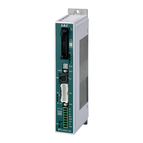
Page 26: Name For Each Parts And Their Functions
PCON-CB/LC POWER CON ■Name for Each Parts and Their Functions■ CB/CGB Type 5) Controller Status Indicator LED 4) PIO Connector /Field Network Connector 6) LED for Power/Alarm Monitoring 7) Axis Number Setting Switch 8) Operation Mode Setting Switch 9) SIO Connector 3) Absolute Battery 10) Motor •... - Page 27 PCON-CB/LC POWER CON Absolute Battery Connector [Refer to Chapter 7] It is the connector to plug in the enclosed battery if applicable for Simple Absolute Type (option). Absolute Battery [Refer to Chapter 7] It is enclosed if applicable for Simple Absolute Type (option). Use unit by affixing it on the side of PCON body with fabric hook-and-loop fastener or store it Absolute Battery Unit (option).
- Page 28 PCON-CB/LC POWER CON LED for Current/Alarm Monitoring In the ordinary use, it shows the command current percentage and shows the alarm code during an alarm being generated. Operation status Status Display • During servo-off: it displays the current command current ratio STS3 (GN) (proportional to the rated current).
- Page 29 PCON-CB/LC POWER CON 11) Brake Release Switch (BK RLS/NOM) For the actuator equipped with a brake, the switch is used to release the brake forcibly. BK RLS ···· Brake forcible release NOM ········ Normal operation (brake is activated) Warning : Always set the switch to “NOM” in normal operation. (Make sure the opportunity to put the switch to RLS side is the minimum and is limited to when startup and adjustment.
-
Page 30: Actuator Axes
PCON-CB/LC POWER CON ■Actuator Axes■ Refer to the pictures below for the actuator axes that can be controlled. 0 defines the home position, and items in ( ) are for the home-reversed type (option). Caution : There are some actuators that are not applicable to the origin reversed type. Check further on the catalog or the Instruction Manual of the actuator. - Page 31 PCON-CB/LC POWER CON (5) Gripper Type (3-Finger Gripper) Finger Attachment (Note) Note Finger attachment is not included in the actuator package. Please prepare separately. (6) Rotary Type (330° Rotation Specification) (Multiple Rotation Specification) 330° 0 - + For Multiple Rotation Type with the origin reversed type, the directions of + and − are the other way around.
- Page 32 PCON-CB/LC POWER CON...
-
Page 33: Chapter 1 Specifications Check
PCON-CB/LC POWER CON Chapter 1 Specifications Check 1.1 Product Check 1.1.1 Parts This product is comprised of the following parts if it is of standard configuration. If you find any fault in the contained model or any missing parts, contact us or our distributor. Part Name Model Quantity... -
Page 34: Teaching Tool
PCON-CB/LC POWER CON 1.1.2 Teaching Tool A teaching tool such as PC software is necessary when performing the setup for position setting, parameter setting, etc. that can only be done on the teaching tool. Please prepare either of the following teaching tools. Part Name Model PC Software... -
Page 35: How To Read The Model Plate
How to Read the Model P C O N - C B - 2 0 P WAI - N P - 2 - 0 - A B - D N– ** <Identification for IAI use only> <Series> * There is no identification in some cases <Type>... -
Page 36: List Of Basic Specifications
PCON-CB/LC POWER CON 1.2 List of Basic Specifications Item PCON-CB/CGB PCON-CFB/CGFB Number of controlled axes 1-axis Power-supply Voltage 24V DC ±10% Load RCP2 Motor 20P, 28P, MAX. 1.0A current RCP3 Type 28SP (including 35P, 42P, MAX. 2.2A control side current 60P, 86P MAX. - Page 37 PCON-CB/LC POWER CON Item PCON-CB/CGB PCON-CFB/CGFB LED Display SV (GN)/ALM (RD) : Servo ON/Alarm generated (mounted on Front Panel) STS0 to 3 : Status display RDY (GN)/ALM (RD) : Absolute function in normal / absolute function error (for the simple absolute type) 1, 0 (GN) (RD) : Absolute function status display (for the simple absolute type)
-
Page 38: Appearance
PCON-CB/LC POWER CON 1.3 Appearance 1.3.1 CB Type For Incremental Screw-fixed Type ・・・・・・ 84.8 69.6... -
Page 39: Cb Type・・・・・・For Incremental Din Rail-Fixed Type
PCON-CB/LC POWER CON 1.3.2 CB Type For Incremental DIN rail-fixed Type ・・・・・・ 93.3 78.1 (for FG cable attachment) -
Page 40: Cb Type・・・・・・For Simple Absolute Screw-Fixed Type
PCON-CB/LC POWER CON 1.3.3 CB Type For Simple Absolute Screw-fixed Type ・・・・・・ 84.8 69.6 (40.5) (58) -
Page 41: Cb Type・・・・・・For Simple Absolute Din Rail-Fixed Type
PCON-CB/LC POWER CON 1.3.4 CB Type For Simple Absolute DIN rail-fixed Type ・・・・・・ 93.3 78.1 (for FG cable attachment) (58) -
Page 42: Cfb Type・・・・・For Incremental Screw-Fixed Type
PCON-CB/LC POWER CON 1.3.5 CFB Type For Incremental Screw-fixed Type ・・・・・ (Note) When using the 84.8 attachment hole on the top of the controller, detach 69.6 the fan unit temporarily. -
Page 43: Cfb Type・・・・・For Incremental Din Rail-Fixed Type
PCON-CB/LC POWER CON 1.3.6 CFB Type For Incremental DIN rail-fixed Type ・・・・・ 93.3 78.1... -
Page 44: Absolute Battery Unit (Option For Simple Absolute Type)
PCON-CB/LC POWER CON 1.3.7 Absolute Battery Unit (Option for Simple Absolute Type) 1) DIN Rail Mounting Type 72.2 66.2 2) Screw Mounting Type 73.5 φ 5 66.2... -
Page 45: I/O Specifications
PCON-CB/LC POWER CON 1.4 I/O Specifications 1.4.1 PIO Input and Output Interface Input Section Output Section Input Voltage 24V DC ±10% Load Voltage 24V DC Peak Load Input Current 5mA 1circuit 50mA 1circuit Specification Electric Current ON/OFF ON Voltage MIN. 18V DC Leakage MAX. -
Page 46: Pulse Train Input Output Interface
PCON-CB/LC POWER CON 1.4.2 Pulse Train Input Output Interface Line Driver Input Sends input pulse (differential voltage: approx. 4V) from the host unit that is installed with a line driver 26C31 or equivalent PCON Host Unit Positioning Unit Specification Pulse Train Including active high and active low Form... -
Page 47: Options
PCON-CB/LC POWER CON 1.5 Options 1.5.1 Pulse converter : AK-04 The pulse converter converts command pulses in the open collector mode to those in the differential mode. Use this converter if the host controller sends output pulses in the open collector mode. Item Specification Input Power Supply... -
Page 48: Installation And Storage Environment
PCON-CB/LC POWER CON 1.6 Installation and Storage Environment This product is capable for use in the environment of pollution degree 2 or equivalent. *1 Pollution Degree 2 : Environment that may cause non-conductive pollution or transient conductive pollution by frost (IEC60664-1) [1] Installation Environment Do not use this product in the following environment. -
Page 49: Noise Elimination And Mounting Method
PCON-CB/LC POWER CON 1.7 Noise Elimination and Mounting Method (1) Noise Elimination Grounding (Frame Ground) Screw fixed type DIN rail fixed type Connect the ground line together to the main unit Connect the ground cable using using the fixing screw. the tapped hole for FG connection on the main unit. - Page 50 PCON-CB/LC POWER CON (4) Heat Radiation and Installation Design and Build the system considering the size of the controller box, location of the controller and cooling factors to keep the surrounding temperature around the controller below 40°C. To fix the units in the control box, use the attachment holes on top and bottom of the unit for the screw fixed type, and use the DIN rails for the DIN rail fixed type.
-
Page 51: Chapter 2 Wiring
PCON-CB/LC POWER CON Chapter 2 Wiring 2.1 Positioner Mode (PIO Control) 2.1.1 Wiring Diagram (Connection of Devices) Host System (PLC, etc.…Please prepare separately) Touch Panel Teaching (to be purchased separately) Power Source I/O Control (24V DC …Please prepare separately) Actuator PC Software Emergency Stop Circuit (to be purchased separately) -
Page 52: Pio Pattern Selection And Pio Signal
PCON-CB/LC POWER CON 2.1.2 PIO Pattern Selection and PIO Signal (1) PIO Pattern (Control Pattern) Selection The controller provides 8 PIO patterns (Control patterns). Set the most suitable PIO pattern with the actual use to Parameter No. 25 “PIO Pattern Select”. Refer to “3.2 Operation in Positioner Mode”... - Page 53 PCON-CB/LC POWER CON (2) PIO Patterns and Signal Assignment The signal assignment of I/O flat cable by the PIO pattern is as shown below. Follow the following table to connect the external equipment (such as PLC). Parameter No.25 “PIO Pattern” Selection Category PIO Functions Positioning mode...
- Page 54 PCON-CB/LC POWER CON Parameter No.25 “PIO Pattern” Selection 6 or 7 Category PIO Functions Solenoid Valve Solenoid Valve Pulse Train Control Mode 1 Mode 2 Mode Number of positioning 7 points 3 points – points Home return signal × Jog signal ×...
- Page 55 PCON-CB/LC POWER CON (3) List of PIO Signals The table below lists the functions of PIO signals. Refer to the section shown in Relevant Sections for the details of the control of each signal. Signal Relevant Category Signal Name Function Description Abbreviation Sections PTP strobe...
- Page 56 PCON-CB/LC POWER CON Signal Relevant Category Signal Name Function Description Abbreviation Sections Turns ON in the positioning band range after actuator operation. 3.2.3 The INP signal will turn OFF if the position deviation exceeds the PEND/INP Position complete 3.2.4 in-position range. PEND and INP can be switched over by the 3.2.5 parameter.
-
Page 57: Wiring
PCON-CB/LC POWER CON 2.1.3 Wiring [1] Power Supply Connector (for Power Supply and Emergency Stop) As an example of a circuit, cases of 4 conditions are shown. Select from 3) or 4) for CGB type. 1) Operate actuator without using the emergency stop input (EMG-) 2) Operate actuator with the emergency stop input (EMG-) activated 3) Stop supplying external motor power at emergency stop input 4) Shut off the motor power externally by inputting the emergency stop with using two units of... - Page 58 PCON-CB/LC POWER CON Example for wiring to operate actuator with the emergency stop input (EMG-) activated Emergency Stop Switch External Emergency of Teaching Pendant Stop Switch Power Supply Connector SIO Connector Teaching Tool Connection Detection Circuit Wiring conducted at delivery (Contact opens Drive Cutoff when connected)
- Page 59 PCON-CB/LC POWER CON Example for wiring to stop supplying external motor power at emergency stop input 24V DC Power Supply External Emergency Stop Switch Emergency Emergency of Teaching Pendant Stop Reset Stop Switch Switch Power Supply Connector SIO Connector Teaching Tool Connection Detection Circuit (Contact opens...
- Page 60 PCON-CB/LC POWER CON Refer to below when shutting the motor power off externally by the emergency stop input when using two or more units of controllers. Emergency-stop Switch on the Emergency Teaching Pendant Stop Reset Emergency PCON Switch Stop Switch Power Supply SIO Connector Connector...
-
Page 61: Motor • Encoder Circuit
PCON-CB/LC POWER CON [2] Motor • Encoder Circuit Connection to RCP2 Series PCON Connection Cable (Note1) Motor/ Encoder Connector Connection to RCP3, RCP4, RCP5 and RCP6 Series PCON Connection Cable (Note1) Motor/ Encoder Connector Note 1 Applicable Connection Cable Model Codes □□□ : Cable Length Example) 030 = 3m Model Name Cable Reference... -
Page 62: Pio Circuit
PCON-CB/LC POWER CON [4] PIO Circuit PIO Pattern 0 ··········· Positioning Mode (Standard Type) 0V(NPN Type) 24V DC(NPN Type) 24V DC(PNP Type) 0V(PNP Type) PCON PIO Connector BR- 1 BR- 3 Completed Position No.1 24V DC RD- 1 RD- 3 Completed Position No.2 Supply OR- 1... - Page 63 PCON-CB/LC POWER CON PIO Pattern 1 ············ Teaching mode (Teaching type) 0V(NPN Type) 24V DC(NPN Type) 24V DC(PNP Type) 0V(PNP Type) PCON PIO Connector BR- 1 BR- 3 Completed Position No.1 24V DC RD- 1 RD- 3 Completed Position No.2 Supply OR- 1 OR- 3...
- Page 64 PCON-CB/LC POWER CON PIO Pattern 2 ············ 256-point mode (Number of positioning points : 256-point type) 0V(NPN Type) 24V DC(NPN Type) 24V DC(PNP Type) 0V(PNP Type) PCON PIO Connector BR- 1 BR- 3 Completed Position No.1 24V DC RD- 1 RD- 3 Completed Position No.2 Supply...
- Page 65 PCON-CB/LC POWER CON PIO Pattern 3 ············ 512-point mode (Number of positioning points : 512-point type) 0V(NPN Type) 24V DC(NPN Type) 24V DC(PNP Type) 0V(PNP Type) PCON PIO Connector BR- 1 BR- 3 Completed Position No.1 24V DC RD- 1 RD- 3 Completed Position No.2 Supply...
- Page 66 PCON-CB/LC POWER CON PIO Pattern 4 ············· Solenoid Valve Mode 1 (7-point type) 0V(NPN Type) 24V DC(NPN Type) 24V DC(PNP Type) 0V(PNP Type) PCON PIO Connector BR- 1 BR- 3 Current Position No.0 24V DC RD- 1 RD- 3 Current Position No.1 Supply OR- 1 OR- 3...
- Page 67 PCON-CB/LC POWER CON PIO Pattern 5 ············· Solenoid Valve Mode 2 (3-point type) 0V(NPN Type) 24V DC(NPN Type) 24V DC(PNP Type) 0V(PNP Type) PCON PIO Connector BR- 1 BR- 3 Backward End Detection 24V DC RD- 1 RD- 3 Forward End Detection Supply OR- 1 OR- 3...
-
Page 68: Pulse Train Control Mode
PCON-CB/LC POWER CON 2.2 Pulse Train Control Mode 2.2.1 Wiring Diagram (Connection of Devices) Host System (PLC, etc.…Please prepare separately) Touch Panel Teaching (to be purchased separately) Power Source I/O Control (24V DC …Please prepare separately) AK-04 AK-04 (to be purchased separately) Necessary when host positioning unit is open collector output. -
Page 69: I/O Signals In Pulse Train Control Mode
PCON-CB/LC POWER CON 2.2.2 I/O Signals in Pulse Train Control Mode [1] PIO Pattern 6 (Incremental Type for Actuator) The table below shows the signal assignment of the flat cable in the “pulse train control mode” to PIO Pattern 6. Follow the following table to connect the external equipment (such as host unit). -
Page 70: Pio Pattern 7 (Incremental Type For Actuator)
PCON-CB/LC POWER CON [2] PIO Pattern 7 (Incremental Type for Actuator) The table below shows the signal assignment of the flat cable in the “pulse train control mode” to PIO Pattern 6. Follow the following table to connect the external equipment (such as host unit). Signal Relevant Category I/O No. -
Page 71: Wiring
PCON-CB/LC POWER CON 2.2.3 Wiring [1] Power Supply Connector (for Power Supply and Emergency Stop) As an example of a circuit, cases of 4 conditions are shown. Select from 3) or 4) for CGB type. 1) Operate actuator without using the emergency stop input (EMG-) 2) Operate actuator with the emergency stop input (EMG-) activated 3) Stop supplying external motor power at emergency stop input 4) Shut off the motor power externally by inputting the emergency stop with using two units of... - Page 72 PCON-CB/LC POWER CON Example for wiring to operate actuator with the emergency stop input (EMG-) activated Emergency Stop Switch External Emergency of Teaching Pendant Stop Switch Power Supply Connector SIO Connector Teaching Tool Connection Detection Circuit Wiring conducted at delivery (Contact opens Drive Cutoff when connected)
- Page 73 PCON-CB/LC POWER CON Example for wiring to stop supplying external motor power at emergency stop input 24V DC Power Supply External Emergency Stop Switch Emergency Emergency of Teaching Pendant Stop Reset Stop Switch Switch Power Supply Connector SIO Connector Teaching Tool Connection Detection Circuit (Contact opens...
- Page 74 PCON-CB/LC POWER CON Refer to below when shutting the motor power off externally by the emergency stop input when using two or more units of controllers. Emergency-stop Switch on the Emergency Teaching Pendant Stop Reset Emergency PCON Switch Stop Switch Power Supply SIO Connector Connector...
-
Page 75: Motor • Encoder Circuit
PCON-CB/LC POWER CON [2] Motor • Encoder Circuit Connection to RCP2 Series PCON Connection Cable (Note1) Motor/ Encoder Connector Connection to RCP3, RCP4, RCP5 and RCP6 Series PCON Connection Cable (Note1) Motor/ Encoder Connector Note 1 Applicable Connection Cable Model Codes □□□ : Cable Length Example) 030 = 3m Model Name Cable Reference... -
Page 76: Pio Circuit
PCON-CB/LC POWER CON [3] PIO Circuit 1) PIO Pattern 6·············· Pulse Train Control Mode (Incremental Type for Actuator) PCON 0V(NPN Type) 24V DC(NPN Type) 24V DC(PNP Type) 0V(PNP Type) PCON PIO Connector BR- 1 BR- 3 System Ready 24V DC RD- 1 RD- 3 Differential Pulse Supply... - Page 77 PCON-CB/LC POWER CON 2) PIO Pattern 7·············· Pulse Train Control Mode (Absolute Type for Actuator) PCON 0V(NPN Type) 24V DC(NPN Type) 24V DC(PNP Type) 0V(PNP Type) ACON, DCON PIO Connector BR- 1 BR- 3 System Ready 24V DC RD- 1 RD- 3 Differential Pulse Supply Servo ON Status...
-
Page 78: Circuits For Pulse Train Control
PCON-CB/LC POWER CON [4] Circuits for Pulse Train Control ● When Host Unit is Differential System It is recommended that PP and /PP and also NP and /NP are PCON Host Unit twisted with each other so the PIO Connector system can be run safely. -
Page 79: Wiring Method
PCON-CB/LC POWER CON 2.3 Wiring Method 2.3.1 Wiring Layout of Power Supply Connector The wires of the power supply and the emergency stop circuit are to be connected to the controller enclosed connector (plug). Strip the sheath of the applicable wires for 10mm and insert them to the connector. 1) Push a protrusion beside the cable inlet with a small slotted screwdriver to open the inlet. -
Page 80: Connection To Actuator
Positive side of the limit switch Negative side of the limit switch Positive side of the brake release Negative side of the brake release Not used Cable dedicated for IAI products Not used * Cable for CB and Encoder A-phase differential + input cable for CFB are different. -
Page 81: Connection Of Pio
PCON-CB/LC POWER CON 2.3.3 Connection of PIO Conduct the connection of I/O to the controller is to be carried out using the dedicated I/O cable. The cable length is shown in the model code of the controller. Please check the controller model code. -
Page 82: Connection Of Pulse Train Signal
If the output pulse of the host controller is open collector type, use the following pulse converter. ● Pulse converter : AK-04 (to be purchased separately) It converts the command pulse of the open collector type to the differential type. Host Controller IAI controller (PLC etc.) e-CON Connector (Accessories) e-CON Connector (Accessories) Model Connector Color... -
Page 83: Sio Connector Connection
PCON-CB/LC POWER CON 2.3.5 SIO Connector Connection SIO connectors can be used not only for the connection of teaching tool, but also for the connection of the host controller (PLC, touch panel and PC). For the operation, refer to the instruction manual of each module. [Refer to 1.1.3 Instruction manuals related to this product, which are contained in the instruction manual (DVD).] Touch Panel Teaching... - Page 84 PCON-CB/LC POWER CON...
-
Page 85: Chapter 3 Operation
PCON-CB/LC POWER CON Chapter 3 Operation Basic Operation 3.1.1 Basic Operation Methods There are two types, Positioner Mode and Pulse Train Control Mode, for the operation. Select the suitable one considering the system function. There are various types of actuators including slider, rod, rotary and gripper types. The same operation control method is applicable unless particular descriptions are contained in this manual. - Page 86 PCON-CB/LC POWER CON • Procedure 3 : Turn the servo ON, and have a home-return operation. 1) Press the Servo 2) Turn on the Servo lamp 3) Press the Home Select Position -> Open Position Table 4) Turn on the Home lamp Edit / Teach in Menu (after actuator is stopped) •...
- Page 87 PCON-CB/LC POWER CON (2) Pulse Train Control Mode Host Controller Command Complete Pulse Signal Signal Enter an electronic gear ratio. Edit Parameters of controller Teaching Tool Actuator Controller ●Operation・・・・Example for When the Parameter Settings at Delivery • Procedure 1 : Establish the settings for the pulse train form and electronic gear ratio (to determine how many millimeters the actuator moves when 1 pulse is given) to the controller parameters by using a teaching tool such as “PC Software”.
-
Page 88: Parameter Settings
PCON-CB/LC POWER CON 3.1.2 Parameter Settings Parameter data should be set to be suited to the system or application. Parameters are variables to be set to meet the use of the controller in the similar way as settings of the ringtone and silent mode of a cell phone and settings of clocks and calendars. -
Page 89: Operation In Positioner Mode
PCON-CB/LC POWER CON 3.2 Operation in Positioner Mode This controller can switch over the mode between positioner mode and pulse train control mode with the parameters. In the positioner mode, the following 6 types of PIO pattern can be selected with a proper parameter. This Operational PIO Pattern cannot be switched over after the system is finished to be established or during the actuator operation. -
Page 90: Overview Of Major Functions
PCON-CB/LC POWER CON [2] Overview of Major Functions Major functions Description Number of positioning Number of positioning points which can be set in the points position table. Operation with the Normal operation started by turning the start signal ON after Position No. -
Page 91: Set Of Position Table
PCON-CB/LC POWER CON 3.2.1 Set of Position Table (This section is not required in selection of pulse train control mode.) The values in the position table can be set as shown below. For only positioning, only the position data may be written if specifying the speed, acceleration, and deceleration is not required. - Page 92 (3) If the payload is extremely lighter than the rated payload, increase accel..., acceleration/deceleration to larger than their rated values to shorten the tact time. Please contact IAI for the settings in such situation. Inform us of the weight, shape and mounting method of the work and the installation conditions of the actuator.
- Page 93 PCON-CB/LC POWER CON Positioning width [mm] ·····For positioning in PIO patterns 0 to 4, the positioning complete signal is output if the remaining moving distance is entered within the zone set here. For pressing, the actuator is moved at the setup velocity and acceleration/deceleration in the same way as normal positioning to the position of the coordinate value set in 2) and then performs pressing movement by the data set here.
- Page 94 PCON-CB/LC POWER CON 11) Acceleration / deceleration mode ······Select a proper acceleration/deceleration pattern depending on the load. Acceleration/ Operation Value Deceleration Pattern Trapezoid Velocity Time S-motion Velocity (Refer to Caution at S-shaped Motion) Time Set the S-motion rate with parameter No.56. First-Order Velocity Lag Filter...
- Page 95 PCON-CB/LC POWER CON 13) Transported load ···· Register 4 types of load weights with using the teaching tool, and choose the number from the registered numbers (0 to 3) that is to be used. From the numbers (load weights) registered in this section, the smart tuning function calculates the optimum speed and acceleration/deceleration.
-
Page 96: Control Of Input Signal
PCON-CB/LC POWER CON 3.2.2 Control of Input Signal The input signal of this controller has the input time constant of 6ms considering the prevention of wrong operation by chattering and noise. (Note 1) Therefore, input each input signal for 6ms or more continuously. -
Page 97: Operation Mode (Rmod, Rmds)
PCON-CB/LC POWER CON [2] Operation Mode (RMOD, RMDS) Input Output PIO signal RMOD RMDS Common to Patterns 0 to 5 : Available, ×: Unavailable Two operation modes are provided so that the operation by PIO signals does not overlap with the operation by a teaching tool such as PC software through SIO communication. -
Page 98: Servo On (Son, Sv, Pend)
PCON-CB/LC POWER CON [3] Servo ON (SON, SV, PEND) Input Output PIO signal Other than pattern 5 Pattern 5 × : Available, ×: Unavailable Servo ON signal SON is the input signal making the servo motor of the actuator operable. If the servo-on is performed to enable operation, the SV output signal is turned ON. -
Page 99: Home Return (Home, Hend, Pend, Move)
PCON-CB/LC POWER CON [4] Home Return (HOME, HEND, PEND, MOVE) Input Output PIO signal HOME HEND PEND MOVE Patterns 0 and 1 Patterns 2 to 4 × (Note1) Pattern 5 × × × : Available, ×: Unavailable Note 1: For pattern 5, the home return by the HOME signal is not allowed. Refer to 3.2.6 [1] Home return (ST0, HEND) for how to perform a home-return operation. - Page 100 PCON-CB/LC POWER CON [Operation of Slider Type/Rod Type Actuator] Mechanical end Home With the HOME signal being ON, the actuator moves toward the mechanical end at the home return speed. The moving speed is 20mm/s for most actuators but less than 20mm/s for some actuators. Refer to the instruction manual of each actuator.
- Page 101 PCON-CB/LC POWER CON (2) Multi-Rotation Specification Home (Forward Rotation End) (Home Position Offset Movement Amount Side) Rotary Axis Datum Point for Offset (Center of 6), 7), 9) and 10)) (Opposite Side of Home Position) Home Sensor Detection Range Once the home-return command is issued, the actuator rotates in CCW (counterclockwise) direction from the view point of the load side.
- Page 102 PCON-CB/LC POWER CON [Operation of Actuator of Gripper Type] (Note 1) Finger Attachment (Note 1) Finger Attachment If the HOME signal is turned ON, the actuator moves toward the mechanical end (to end side) at the home return speed (20mm/s). The actuator is turned at the mechanical end and stopped at the home position.
-
Page 103: Zone Signal And Position Zone Signal (Zone1, Zone2, Pzone)
PCON-CB/LC POWER CON [5] Zone Signal and Position Zone Signal (ZONE1, ZONE2, PZONE) Output PIO signal (Note 2) (Note 2) ZONE1 ZONE2 PZONE Pattern 0 (Note 2) Pattern 1 × (Note 2) Pattern 2 × (Note 1) Pattern 3 × ×... - Page 104 PCON-CB/LC POWER CON (2) Position zone signal (PZONE) Accele- Decele- Thresh- Positioning Acceleration/ Position Velocity Pressing Zone+ Zone- Incre- Transported Stop ration ration width Deceleration [mm] [mm/s] [mm] [mm] mental load mode [mm] mode 0.00 250.00 0.20 0.20 0.10 50.00 30.00 100.00 250.00...
-
Page 105: Alarm, Alarm Reset (*Alm, Res)
PCON-CB/LC POWER CON [6] Alarm, Alarm Reset (*ALM, RES) Input Output PIO signal *ALM Common to Patterns 0 to 5 : Available, ×: Unavailable Alarm signal *ALM is set to ON in the normal status but turned OFF at the occurrence of an alarm at a level equal to or higher than the operation release level. -
Page 106: Binary Output Of Alarm Data Output (*Alm, Pm1 To 8)
PCON-CB/LC POWER CON [7] Binary Output of Alarm Data Output (*ALM, PM1 to 8) Output PIO signal *ALM PM1 to 8 Common to Patterns 0 to 3 (Note 1) Pattern 4 × (Note 1) Pattern 5 × : Available, ×: Unavailable Note 1 Patterns 4 and 5 do not have this function. - Page 107 PCON-CB/LC POWER CON : ON : OFF ALM8 ALM4 ALM2 ALM1 *ALM Binary Code Description: Alarm code is shown in ( ). (PM8) (PM4) (PM2) (PM1) Actual speed excessive (0C0) Regenerative electric discharge circuit error (0C7) Overcurrent (0C8) Overvoltage (0C9) Overheat (0CA) Control power source voltage error (0CC) Drop in control supply voltage (0CE)
-
Page 108: Brake Release (Bkrl)
PCON-CB/LC POWER CON [8] Brake Release (BKRL) Input PIO signal BKRL Pattern 0 (Note 1) Pattern 1 × Pattern 2 to 5 : Available, ×: Unavailable Note 1 Pattern 1 does not have this feature The brake can be released while BKRL signal is set to ON. If a brake is installed in the actuator, the brake is automatically controlled by servo ON/OFF. -
Page 109: Operation With The Position No. Input = Operations Of Pio Patterns 0 To 3
PCON-CB/LC POWER CON 3.2.4 Operation with the Position No. Input = Operations of PIO Patterns 0 to 3 This section describes the methods of operations of PIO patterns 0 to 3. These patterns provide normal controller operation methods in which the controller is operated by turning the start signal ON after a position No. - Page 110 PCON-CB/LC POWER CON Sample use 1) 2) 3) 4) 7) 8) Velocity Positioning Completion Signal Output Positioning Completion Signal Output Accele- Decele- Thresh- Positioning Acceleration/ Position Velocity Pressing Zone+ Zone- Incre- Transported Stop ration ration width Deceleration [mm] [mm/s] [mm] [mm] mental load...
- Page 111 PCON-CB/LC POWER CON Command position No. PC1 to PC** (PLC→Controller) T1≥6ms Turned OFF by Start signal CSTR turning PEND OFF (PLC→Controller) Completed position (Note 1) PM1 to PM**=0 (Note 1) PM1 to PM**=0 PM1 to PM** (Controller→PLC) Turned ON after Target Position entering into Positioning Completion Signal...
- Page 112 PCON-CB/LC POWER CON [Shortcut control of rotary actuator of multi-rotation specification] (1) Set of shortcut selection The shortcut selection can be made valid/invalid by Parameter No.80 “shortcut selection during rotation”. If the shortcut selection is made valid, the actuator can be moved only in a single direction.
- Page 113 PCON-CB/LC POWER CON (2) Infinite Rotation Control Making the shortcut selection valid and moving the actuator in a specific direction continuously allows the actuator to be rotated continuously as a motor. The continuous operation can be done as described below. [Operation Examples] This example rotates the actuator by 2 turns and finally stops it at position No.4.
-
Page 114: Speed Change During The Movement
PCON-CB/LC POWER CON [2] Speed Change During the Movement Sample use 1) 2) 6) 7) Positioning complete width at position 2 Velocity Positioning Completion Signal Output Positioning Completion Signal Output Accele- Decele- Thresh- Positioning Acceleration/ Position Velocity Pressing Zone+ Zone- Incre- Transported Stop... -
Page 115: Pitch Feeding (Relative Movement = Incremental Feed)
PCON-CB/LC POWER CON [3] Pitch Feeding (Relative Movement = Incremental Feed) Sample use 2) 3) Velocity Accele- Decele- Thresh- Positioning Acceleration/ Position Velocity Pressing Zone+ Zone- Incre- Transported Stop ration ration width Deceleration [mm] [mm/s] [mm] [mm] mental load mode [mm] mode 100.00... - Page 116 PCON-CB/LC POWER CON Caution: (1) If the actuator reaches the software limit corresponding to the stroke end in the pitch feed operation, the actuator stops at the position and positioning complete signal PEND is turned ON. (2) Note that, in pitch feed just after pressing operation (to be in the pressing state), the start position is not the stop position at the completion of pressing but the coordinate value entered in “Position”...
-
Page 117: Pressing Operation
PCON-CB/LC POWER CON [4] Pressing Operation Sample use 1) 2) 4) 5) Positioning width 50 Press-fitting process Velocity Caulking process Accele- Decele- Thresh- Positioning Acceleration/ Position Velocity Pressing Zone+ Zone- Incre- Transported Stop ration ration width Deceleration [mm] [mm/s] [mm] [mm] mental load... - Page 118 PCON-CB/LC POWER CON Command position No. PC1 to PC** (PLC→Controller) (Note 1) T1≥6ms Turned OFF by turning Start signal CSTR PEND OFF (PLC→Controller) Completed position (Note 2) (Note 2) PM1 to PM** PM1 to PM** = 0 PM1 to PM** = 0 (Controller→PLC) Not turned ON for Positioning Completion Signal...
- Page 119 PCON-CB/LC POWER CON Caution: (1) The speed during pressing operation is set in Parameter No.34. Check the 10.6 List of Specifications of Connectable Actuators for the pressing operation speed. Do not set any value larger than the value in the list. If the speed set in the position table is equal to or less than the pressing speed, the pressing is performed at the setup speed.
- Page 120 PCON-CB/LC POWER CON Judging completion of pressing operation The operation monitors the torque (current limit value) in percent in “Pressing” of the position table and turns pressing complete signal PEND ON when the load current satisfies the condition shown below during pressing. PEND is turned ON at satisfaction of the condition if the work is not stopped.
- Page 121 PCON-CB/LC POWER CON Command Torque Level Detection at Pressing This is a function to detect whether the specified load is applied to the actuator by checking the torque while in press-fitting operation when having a press-fitting process with the pressing operation. If there is no resistance in press-fitting, the specified load would not be applied, thus it is defined as the normal pressing is not conducted and an alarm can be issued from PLC.
-
Page 122: Tension Operation
PCON-CB/LC POWER CON [5] Tension Operation Image diagram Position No.1 Position No.2 Accele- Decele- Thresh- Positioning Acceleration/ Position Velocity Pressing Zone+ Zone- Incre- Transported Stop ration ration width Deceleration [mm] [mm/s] [mm] [mm] mental load mode [mm] mode 100.00 250.00 0.20 0.20 0.10... - Page 123 PCON-CB/LC POWER CON First define the positioning in position No.1. Next, the operation in position No.2 moves the actuator to the position of 80mm at the setting speed and rating torque and change to the tension operation. The actuator moves by 50mm in the negative direction in the tension operation.
-
Page 124: Multi-Step Pressing
PCON-CB/LC POWER CON [6] Multi-step Pressing Image diagram Position No.1 Position No.2 Position No.3 Accele- Decele- Thresh- Positioning Acceleration/ Position Velocity Pressing Zone+ Zone- Incre- Transported Stop ration ration width Deceleration [mm] [mm/s] [mm] [mm] mental load mode [mm] mode 0.00 250.00 0.20... -
Page 125: Teaching By Pio (Mode, Modes, Pwrt, Wend, Jisl, Jog+, Jog-)
PCON-CB/LC POWER CON [7] Teaching by PIO (MODE, MODES, PWRT, WEND, JISL, JOG+, JOG-) Input Output PIO signal MODE JISL JOG+ JOG- PWRT MODES WEND Other than × × × × × × × pattern 1 Pattern 1 : Existence of signal, ×: No signal (Note) The feature is available only in pattern 1. - Page 126 PCON-CB/LC POWER CON Warning: (1) In home return incomplete state, software limit cannot stop the actuator. Take interlock and prohibit the operation or perform the operation carefully. (2) If the JISL signal is changed during inching operation, the inching being operated is continued.
-
Page 127: Pause And Operation Interruption (*Stp, Res, Pend, Move)
PCON-CB/LC POWER CON Caution: (1) Set the period taken from entering position No. to turning the PWRT ON to 6ms or longer. In spite of 6ms timer process in the PLC, commands may be input to the controller concurrently to cause writing to another position. Take the scanning time in the PLC into account, set a period as 2 to 4 times as the scanning time. - Page 128 PCON-CB/LC POWER CON Control method Pause is possible during movement. In addition, the remaining moving distance can be cancelled to interrupt the operation. The pause signal is an input signal always set to ON. So, it is normally used to remain ON. Use this function for interlock in case where an object is invaded into the moving direction of the actuator being moved.
-
Page 129: Direct Position Specification (Solenoid Valve Mode 1) = Operation Of Pio Pattern 4
PCON-CB/LC POWER CON 3.2.5 Direct Position Specification (Solenoid Valve Mode 1) = Operation of PIO Pattern 4 The start signal is provided for every position number. Only turning ON the relevant input signal according to the table shown below allows the operation based on the data in the target position number to be performed. - Page 130 PCON-CB/LC POWER CON Control method When start signal ST* is turned ON, the actuator starts acceleration based on the data in the specified position table for positioning to the target position. At the completion of positioning, positioning complete signal PEND is turned ON as well as current position No.
-
Page 131: Pitch Feeding (Relative Movement = Incremental Feed)
PCON-CB/LC POWER CON [2] Pitch Feeding (Relative Movement = Incremental Feed) Sample use 2) 3) Velocity Accele- Decele- Thresh- Positioning Acceleration/ Position Velocity Pressing Zone+ Zone- Incre- Transported Stop ration ration width Deceleration [mm] [mm/s] [mm] [mm] mental load mode [mm] mode 100.00... - Page 132 PCON-CB/LC POWER CON Caution: (1) Because pitch feed is repeated, turning ON the ST* signal of the same position after completion of positioning causes both the PE* and PEND signals to be turned OFF at operation start and turned ON again at completion of positioning in the same way as [1] Positioning.
-
Page 133: Pressing Operation
PCON-CB/LC POWER CON [3] Pressing Operation Sample use 3) 4) Positioning width 50 Press-fitting process Velocity Positioning Completion Caulking process Accele- Decele- Thresh- Positioning Acceleration/ Position Velocity Pressing Zone+ Zone- Incre- Transported Stop ration ration width Deceleration [mm] [mm/s] [mm] [mm] mental load... - Page 134 PCON-CB/LC POWER CON Turned OFF by turning PEND ON Start signal (PLC→Controller) Turned on even Current Position No. in miss-pressing (Controller→PLC) Not turned ON for Positioning Completion Signal miss-pressing PEND (Controller→PLC) Pressing Pressing Operation of actuator Approach operation operation complete Positioning be Movement by Stop of...
- Page 135 PCON-CB/LC POWER CON Judging completion of pressing operation The operation monitors the torque (current limit value) in percent in “Pressing” of the position table and turns pressing complete signal PEND ON when the load current satisfies the condition shown below during pressing. PEND is turned ON at satisfaction of the condition if the work is not stopped.
- Page 136 PCON-CB/LC POWER CON Command Torque Level Detection at Pressing This is a function to detect whether the specified load is applied to the actuator by checking the torque while in press-fitting operation when having a press-fitting process with the pressing operation. If there is no resistance in press-fitting, the specified load would not be applied, thus it is defined as the normal pressing is not conducted and an alarm can be issued from PLC.
-
Page 137: Tension Operation
PCON-CB/LC POWER CON [4] Tension Operation Image diagram Position No.1 Position No.2 Accele- Decele- Thresh- Positioning Acceleration/ Position Velocity Pressing Zone+ Zone- Incre- Transported Stop ration ration width Deceleration [mm] [mm/s] [mm] [mm] mental load mode [mm] mode 100.00 250.00 0.20 0.20 0.10... - Page 138 PCON-CB/LC POWER CON First define the positioning in position No.1. Next, the operation in position No.2 moves the actuator to the position of 80mm at the setting speed and rating torque and change to the tension operation. The actuator moves by 50mm in the negative direction in the tension operation.
-
Page 139: Multi-Step Pressing
PCON-CB/LC POWER CON [5] Multi-step Pressing Image diagram Position No.1 Position No.2 Position No.3 Accele- Decele- Thresh- Positioning Acceleration/ Position Velocity Pressing Zone+ Zone- Incre- Transported Stop ration ration width Deceleration [mm] [mm/s] [mm] [mm] mental load mode [mm] mode 0.00 250.00 0.20... -
Page 140: Pause And Operation Interruption (St*, *Stp, Res, Pe*, Pend)
PCON-CB/LC POWER CON [6] Pause and Operation Interruption (ST*, *STP, RES, PE*, PEND) Pause is possible during movement. In this mode, the following two methods are possible for pause. Use of pause signal *STP Turning reset signal RES ON during the pause allows the remaining moving distance to be cancelled to interrupt the operation. - Page 141 PCON-CB/LC POWER CON Note 1 Caution: (1) At occurrence of an alarm in the release level , RES can reset the alarm. Cancel the remaining moving distance after confirmation that alarm signal *ALM (being ON in normal state and OFF at occurrence of an alarm) is set to ON.
-
Page 142: Direct Position Specification (Solenoid Valve Mode 2) = Operation Of Pio Pattern 5
PCON-CB/LC POWER CON 3.2.6 Direct Position Specification (Solenoid Valve Mode 2) = Operation of PIO Pattern 5 The start signal is provided for every position number. Only turning ON the relevant input signal according to the table shown below allows the operation based on the data in the target position number to be performed. - Page 143 PCON-CB/LC POWER CON [Operation of Slider Type/Rod Type Actuator] Mechanical end Home With the ST0 signal being ON, the actuator moves toward the mechanical end at the home return speed. The moving speed is 20mm/s for most actuators but less than 20mm/s for some actuators. Check the instruction manual of actuator.
- Page 144 PCON-CB/LC POWER CON (2) Multi-Rotation Specification Home (Forward Rotation End) (Home Position Offset Movement Amount Side) Rotary Axis Datum Point for Offset (Center of 6), 7), 9) and 10)) (Opposite Side of Home Position) Home Sensor Detection Range Once the home-return command is issued, the actuator rotates in CCW (counterclockwise) direction from the view point of the load side.
- Page 145 PCON-CB/LC POWER CON [Operation of Actuator of Gripper Type] (Note 1) Finger Attachment (Note 1) Finger Attachment If the HOME signal is turned ON, the actuator moves toward the mechanical end (to end side) at the home return speed (20mm/s). The actuator is turned at the mechanical end and stopped at the home position.
-
Page 146: Features Of Ls Signals (Ls0 To 2)
PCON-CB/LC POWER CON [2] Features of LS Signals (LS0 to 2) The LS* signals are not complete signals for positioning commands such as those for other PIO patterns. Despite the specified position No., the corresponding LS* signal is turned ON when the actuator is entered into the setup value range as if the actuator were detected by a sensor installed. -
Page 147: Positioning [Basic] (St0 To St2, Ls0 To Ls2)
PCON-CB/LC POWER CON [3] Positioning [Basic] (ST0 to ST2, LS0 to LS2) Position No. Input Output (Note) Pressing and pitch feed are unavailable. Sample use 2) 3) 5) 6) Velocity Accele- Decele- Thresh- Positioning Acceleration/ Position Velocity Pressing Zone+ Zone- Incre- Transported Stop... - Page 148 PCON-CB/LC POWER CON (Example) Repetition of ST1 → ST2 → ST1 →・・・ Insert timer Δt if necessary. Start signal Δt Δt (PLC→Controller) Δt Start signal (PLC→Controller) Position sensing output (Controller→PLC) Turned ON after Position sensing output entering into positioning width zone (Controller→PLC) Target Position Δt : Time required to certainly reach the target position after the position sensing output LS1 or 2 is turned on.
-
Page 149: Speed Change During The Movement
PCON-CB/LC POWER CON [4] Speed Change During the Movement Sample use 2) 3) 4) 5) Positioning complete width at position 1 Velocity Accele- Decele- Thresh- Positioning Acceleration/ Position Velcoty Pressing Zone+ Zone- Incre- Transported Stop ration ration width Deceleration [mm] [mm/s] [mm] [mm]... - Page 150 PCON-CB/LC POWER CON The timing chart shown below indicates that the actuator changes its speed while it moves to position No.1 after the completion of positioning at position No.2 and moves to position No.0. Start signal (PLC→Controller) Start signal (PLC→Controller) Start signal (PLC→Controller) Position sensing Output...
-
Page 151: Pause And Operation Interruption (St*, *Stp, Res, Pe*, Pend)
PCON-CB/LC POWER CON [5] Pause and Operation Interruption (ST*, *STP, RES, PE*, PEND) Turning start signal ST* OFF allows the actuator to be paused while it is moved. To restart it, turn the same ST* signal ON. Velocity Control method If start signal ST* is turned OFF during movement, the actuator can be paused. -
Page 152: Pulse Train Control Mode (For Pulse Train Type)
PCON-CB/LC POWER CON 3.3 Pulse Train Control Mode (for Pulse Train Type) This controller can switch over the mode between positioner mode and pulse train control mode with the parameters. In Pulse Train Mode, there are 2 types, incremental type for actuator (PIO Pattern 6) and (Battery-less) absolute type for actuator (PIO Pattern 7), the actuator can be operated by the pulse train output of the host controller (PLC) positioning control function. -
Page 153: I/O Signal Controls
PCON-CB/LC POWER CON 3.3.1 I/O Signal Controls The input signals of this controller incorporate an input time constant to prevent malfunction due to chattering, noise, etc. Make sure to input the signals continuously for 6ms or more. (Note) Command pulse train inputs (PP, /PP, NP, /NP) do not have input time constants. Also, it is necessary to input 16ms or more for CSTP Signal. -
Page 154: Operation Mode (Rmod, Rmds)
PCON-CB/LC POWER CON [3] Operation Mode (RMOD, RMDS) Input Output PIO signal RMOD RMDS Two operation modes are provided so that the operation by PIO signals does not overlap with the operation by a teaching tool such as PC software through SIO communication. The mode change is done by the operation mode setting switch on the front panel of the controller. -
Page 155: Compulsory Stop (Cstp)
PCON-CB/LC POWER CON [4] Compulsory Stop (CSTP) Input PIO signal CSTP This signal is used to forcibly stop the actuator. Input the CSTP signal continuously for 16ms or longer. Once the CSTP signal is received, the actuator decelerates and stops with the maximum torque, and then turns the servo OFF. At this time, the deviation counter is cleared. -
Page 156: Home Return (Home, Hend)
PCON-CB/LC POWER CON Servo OFF status 1. Once the actuator stops, no retaining torque will be supplied. 2. The pulse train input, HOME (home return signal), TL (torque-limiting selection signal) and CSTP (external forced stop signal) are all ignored. 3. Output signals SV (ready signal), HEND (home return complete signal) and TLR (torque limiting signal) are all cleared (turned OFF). - Page 157 PCON-CB/LC POWER CON [Operation of Slider Type/Rod Type Actuator] Mechanical end Home With the HOME signal being ON, the actuator moves toward the mechanical end at the home return speed. The moving speed is 20mm/s for most actuators but less than 20mm/s for some actuators. Check the instruction manual of each actuator.
- Page 158 PCON-CB/LC POWER CON (2) Multi-Rotation Specification Home (Forward Rotation End) (Home Position Offset Movement Amount Side) Rotary Axis Datum Point for Offset (Center of 6), 7), 9) and 10)) (Opposite Side of Home Position) Home Sensor Detection Range Once the home-return command is issued, the actuator rotates in CCW (counterclockwise) direction from the view point of the load side.
-
Page 159: Datum Position Move (Rstr, Rend)
PCON-CB/LC POWER CON [Operation of Actuator of Gripper Type] (Note 1) Finger Attachment (Note 1) Finger Attachment If the HOME signal is turned ON, the actuator moves toward the mechanical end (to end side) at the home return speed (20mm/s). The actuator is turned at the mechanical end and stopped at the home position. -
Page 160: Zone (Zone1, Zone2)
PCON-CB/LC POWER CON [8] Zone (ZONE1, ZONE2) Output PIO signal ZONE1 ZONE2 Each of the signals turns ON when the current actuator position is inside the range specified by the relevant parameter. Two zones, ZONE1 and ZONE2, can be set. When the current position of the actuator is in ZONE1, it is turned ON if it is in the range of Parameter No.1 “Zone Boundary 1 Positive Side”... -
Page 161: Alarm, Alarm Reset (*Alm, Res)
PCON-CB/LC POWER CON [9] Alarm, Alarm Reset (*ALM, RES) Input Output PIO signal *ALM Alarm signal *ALM is set to ON in the normal status but turned OFF at the occurrence of an alarm at a level equal to or higher than the operation release level. Turning reset signal RES ON under occurrence of an alarm at the operation release level (Note 1) allows the alarm... -
Page 162: Brake Forcible Release (Bkrl)
PCON-CB/LC POWER CON : ON : OFF *ALM ALM8 ALM4 ALM2 ALM1 Binary Code Description: Alarm code is shown in ( ). Actual Velocity Excessive (0C0) Overcurrent (0C8) Overvoltage (0C9) Overheat (0CA) Current sensor offset adjustment error (0CB) Control power source voltage error (0CC) Drop in control supply voltage (0CE) I/O 24V power supply error (0CF) Drive source error (0D4) -
Page 163: Pulse Train Input Operation
PCON-CB/LC POWER CON 3.3.3 Pulse Train Input Operation [1] Command Pulse Input (PP•/PP, NP•/NP) In the differential type, it is able to have 200kpps of pulse train input at maximum. When the host controller possesses only the pulse output function of the open collector, it is able to input 60kpps pulse at maximum by connecting AK-04 (option). -
Page 164: Position Complete (Inp)
PCON-CB/LC POWER CON Caution: Consider the electric gear ratio of the host side and that of the controller side via the following calculation. (Reference) Acceleration/deceleration settings of general positioning device Motor Rotation Velocity [mm/s] × 60 Motor Rotation [rpm] = Ball Screw •... -
Page 165: Torque Limit Select (Tl, Tlr)
PCON-CB/LC POWER CON [3] Torque Limit Select (TL, TLR) Input Output PIO signal This signal is used to limit the torque of the motor. While the TL signal is ON, the actuator thrust (motor torque) can be limited to the torque set in Parameter No.57 “Torque limit”. -
Page 166: Settings Of Basic Parameters Required For Operation
PCON-CB/LC POWER CON 3.3.4 Settings of Basic Parameters Required for Operation It is a mandatory parameter to perform an operation. (The parameters listed in the table below may only be set if the actuator performs only positioning operation.) Parameter No. Parameter Name Details Electronic Gear Numerator This parameter determines the unit travel distance of... - Page 167 PCON-CB/LC POWER CON Examples of electronic gear calculations: To set the unit travel distance to 0.01 (1/100) mm for an actuator a ball screw lead of 3mm, equipped with an encoder of 800pulses/rev. Electronic Gear Numerator (CNUM) No. of Encoder Pluses [pulse/rev] ×...
-
Page 168: Format Settings Of Command Pulse Train
PCON-CB/LC POWER CON [2] Format Settings of Command Pulse Train Set the format of command pulse train in Parameter No.63 and active high/low in No.64. (1) Command Pulse Mode Initial Name Symbol Unit Input Range Value Command Pulse Input Mode 0 to 2 Setting Value Input... -
Page 169: Parameter Settings Required For Advanced Operations
PCON-CB/LC POWER CON 3.3.5 Parameter Settings Required for Advanced Operations Depending on systems and/or loads, set the following parameters if necessary. [1] Position Command Primary Filter Time Constant Input Initial Name Symbol Unit Range Value Position command primary 0.0 to PLPF msec filter time constant... -
Page 170: Error Monitor During Torque Limiting
PCON-CB/LC POWER CON [4] Error Monitor During Torque Limiting Input Initial Name Symbol Unit Range Value Error monitor during torque limiting FSTP – 0 to 1 You can select whether to enable or disable the function to monitor deviation while torque is being limited (the TL signal is ON). -
Page 171: Chapter 4 Field Network
PCON-CB/LC POWER CON Chapter 4 Field Network Applicable for the fieldbus shown in the list below. Except for RS485 (Modbus), it is the option which can be selected when purchasing. It cannot be changed after the product is delivered. Also, for the fieldbus other than RS485, PIO cannot be equipped. And Pulse Train Mode cannot be operated. - Page 172 PCON-CB/LC POWER CON [Reference] Wiring Layout of Fieldbus (for Fieldbus type) Follow the instruction manual of the master unit and PLC consists of each fieldbus for the details of how to perform connections. 1) DeviceNet Type 2) CC-Link Type 3) PROFIBUS-DP Type...
- Page 173 PCON-CB/LC POWER CON 4) CompoNet Type 5) EtherNet/IP Type 6) MECHATROLINK-Ⅰ/Ⅱ Type...
- Page 174 PCON-CB/LC POWER CON 7) EtherCAT Type 8) PROFINET-IO Type...
-
Page 175: Chapter 5 Collision Detection Feature
PCON-CB/LC POWER CON Chapter 5 Collision Detection Feature This controller is equipped with a feature to stop immediately when the actuator is hit on an object during operation. Understand this chapter well to avoid any trouble in operation and safety. Collision detection feature is a feature that stops the operation by generating an alarm and turning OFF the servo when the command current exceeds the set value. -
Page 176: Settings
PCON-CB/LC POWER CON Settings Have the following settings established when using following function. 1) Select to use feature Setting can be established in the parameters. Setting of parameter ” No.168 Collision Detection Feature” Setting value Operation status Alarm level Detection not to be conducted Detection is conducted in position zone setting range. -
Page 177: Chapter 6 Power-Saving Function
PCON-CB/LC POWER CON Chapter 6 Power-saving Function Automatic Servo-off and Full Servo Functions This controller possesses Automatic Servo-off and Full Servo functions to reduce the power consumption while the actuator is stopped. Read the description in this chapter carefully to save power so that the controller can be operated safely. - Page 178 PCON-CB/LC POWER CON (1) Setting of periods taken until automatic servo-off Three periods from completion of positioning to automatic servo-off can be set in the following parameters in seconds [sec]. Parameter No. Description Auto Servo Motor OFF Delay Time 1 (Unit: sec) Auto Servo Motor OFF Delay Time 2 (Unit: sec) Auto Servo Motor OFF Delay Time 3 (Unit: sec) (2) Set of power-saving mode...
- Page 179 PCON-CB/LC POWER CON [For Parameter No.39 = 0] Positioning Automatic servo Positioning Operation of actuator Servo OFF operation OFF standby operation Servo Condition Completed Position No. PM1 to ** =0 PM1 to ** = Output PM1 to ** = 0 PM1 to ** = 0 Output (Current position (PE** = OFF)
-
Page 180: Automatic Current Reduction Feature
PCON-CB/LC POWER CON Automatic Current Reduction Feature This feature reduces the current at stop gradually when the actuator is able to keep staying at the same stop position (condition with no deviation) after stopping for positioning. In case the actuator has moved, the current at stop increases gradually until the stop condition gets retained. -
Page 181: Chapter 7 Absolute Reset And Absolute Battery
PCON-CB/LC POWER CON Chapter 7 Absolute Reset and Absolute Battery Absolute Reset In Simple Absolute Type and Battery-less Absolute Type, the encoder position information is retained even when the power is OFF. For those types, it is unnecessary to perform home-return operation every time the power is turned ON. - Page 182 PCON-CB/LC POWER CON (2) For Teaching Pendant (TB-02/TB-03) Press Alarm reset. Press Trial Operation on the Menu 1 screen. Press Jog inching on Test run screen. Touch Servo to turn the servo ON and touch Homing in Jog inching screen.
- Page 183 PCON-CB/LC POWER CON (3) For Teaching Pendant (TB-01) Press Reset Alm. Press Trial Operation on the Menu 1 screen. Press Jog_Inching on Trial Operation screen. Touch SV OFF to turn the servo ON and touch HOME in Jog screen.
-
Page 184: Absolute Reset Using Pio
PCON-CB/LC POWER CON [2] Absolute Reset Using PIO Turn the reset signal RES from OFF to ON. (Processed with ON edge.) (Note 1) Check that the alarm signal *ALM is ON (controller’s alarm is cancelled). (Note 1) If the cause of the alarm is not removed, an alarm will be present again (*ALM signal OFF). - Page 185 PCON-CB/LC POWER CON [Absolute Reset Process] Emergency stop actuated or cancelled Safety Circuit Condition (Status of power supply to the motor drive source) (Note 1) 24V DC PIO Power Input Brake Power Input (Note 2) Control Power Input Motor Power Input Alarm reset Alarm Signal (*ALM)
-
Page 186: Absolute Battery (For Simple Absolute Type)
PCON-CB/LC POWER CON Absolute Battery (for Simple Absolute Type) [1] For the Type to Attach Battery to Controller Side Absolute battery and fabric hook-and-loop faster are enclosed in the simple absolute type controllers. The absolute battery is used to back up the absolute data. Separate the faster and attach one on the side surface of the controller and the other on the absolute battery. -
Page 187: Absolute Battery Voltage Drop Detection
PCON-CB/LC POWER CON (Example) From Monday to Friday ; charge for 8 hours per day, discharge for 16 hours, Saturday and Sunday ; use with discharge 1) If the upper limit setting for the number of encoder revolution is 800 [PRM]; Full charge amount : 24 [h] *5 [day] = 120 [h]... -
Page 188: Replacement Of Absolute Battery
PCON-CB/LC POWER CON 7.2.4 Replacement of Absolute Battery When replacing the battery, leave the power to the controller ON, remove the battery connector and replace with a new battery. [1] For the Type to Attach Battery to Controller Side [Removal] Pull the connector to remove the battery. -
Page 189: When Using Absolute Battery Unit
PCON-CB/LC POWER CON [2] When Using Absolute Battery Unit 1) Detach the absolute battery connector first, and then remove the absolute battery unit cover retaining screws (2 places) to detach the cover. At this time, pull out the battery cables from the opening on the cover. - Page 190 PCON-CB/LC POWER CON...
-
Page 191: Chapter 8 Parameter
PCON-CB/LC POWER CON Chapter 8 Parameter Parameters are the data to set up considering the system and application. When a change is required to the parameters, make sure to back up the data before the change so the settings can be returned anytime. With using PC software, it is able to store the backup to the PC. -
Page 192: Parameter List
PCON-CB/LC POWER CON 8.1 Parameter List The categories in the table below indicate whether parameters should be set or not. There are five categories as follows: A : Check the settings before use. B : Use parameters of this category depending on their uses. C : Use parameters of this category with the settings at shipments leaving unchanged as a rule. - Page 193 PCON-CB/LC POWER CON I/O Parameter List (Continued) for Pulse Default factory Relevant (Note1) Name Symbol Unit Input Range Positioner Train setting sections Mode Mode 0: Level B Movement command type FPIO – 8.2 [20] 1: Edge Default movement direction for 0: Reverse In accordance with PHSP...
- Page 194 PCON-CB/LC POWER CON I/O Parameter List (Continued) for Pulse Default factory Relevant (Note1) Name Symbol Unit Input Range Positioner Train setting sections Mode Mode 0: Enabling B Deviation counter clear input DCLR – 3.3.5 [5] 1: Disabling 0: Enabling B Torque limit command input –...
- Page 195 PCON-CB/LC POWER CON I/O Parameter List (Continued) for Pulse Default factory Relevant Name Symbol Unit Input Range Positioner Train setting sections Mode Mode 0.0.0.0 to Separate B IP address IPAD – Separate volume 255.255.255.255 volume 0.0.0.0 to Separate B Subnet mask SNMK –...
-
Page 196: Detail Explanation Of Parameters
PCON-CB/LC POWER CON 8.2 Detail Explanation of Parameters Caution: • If parameters are changed, provide software reset or reconnect the power to reflect the setting values. • The unit (deg) is for rotary actuator and lever type gripper. Pay attention that it is displayed in mm in the teaching tools. - Page 197 PCON-CB/LC POWER CON [2] Soft limit+, Soft limit- (Parameter No.3, No.4) Default factory Name Symbol Unit Input Range setting -9999.99 to Actual stroke on Soft limit + LIMM (deg) 9999.99 + side -9999.99 to Actual stroke on - Soft limit - LIML (deg) 9999.99...
- Page 198 PCON-CB/LC POWER CON [4] Press & hold stop judgment period (Parameter No.6) Default factory Name Symbol Unit Input Range setting Press & hold stop judgment PSWT msec 0 to 9999 period Judging completion of pressing operation (1) For Standard type (PIO pattern 0 to 3) The operation monitors the torque (current limit value) in percent in “Pressing”...
- Page 199 When the value is increased, the stop holding torque is increased. Even though it is generally unnecessary to change this setting, setting the value larger is necessary in the case a large external force is applied during stop. Please contact IAI.
- Page 200 Normally this parameter need not be changed. If the home return should be completed before the correct position depending on the affixing method, load condition or other factors when the actuator is used in a vertical application, the setting value must be increased. Please contact IAI. [11] Pause input disable (Parameter No.15) Default factory...
- Page 201 Offset. Normal excitation detection cannot be performed, and there may be a risk of generating the excitation detection error or casing abnormal noise. In case there is a necessity of setting a value less than the initial setting, contact IAI.
- Page 202 PCON-CB/LC POWER CON [17] Zone Boundary 2+, Zone Boundary 2- (Parameter No.23, No.24) [Refer to 8.2 [1].] [18] PIO pattern selection (Parameter No.25) Default factory Name Symbol Unit Input Range setting 0 (Standard Type) PIO pattern selection IOPN – 0 to 7 6 (Pulse train controll type) Select the PIO operation pattern in Parameter No.25.
- Page 203 PCON-CB/LC POWER CON [19] PIO jog velocity (Parameter No.26) Default factory Name Symbol Unit Input Range setting mm/s 1 to Actuator’s max. PIO jog velocity IOJV (note1) (deg/s) speed This is the jog operation velocity setting with PIO signal (jog input command) when PIO pattern = 1 (Teaching Mode) is selected.
- Page 204 PCON-CB/LC POWER CON [21] Default movement direction for excitation-phase signal detection (Parameter No.28) Default factory Name Symbol Unit Input Range setting 0 : Reversed Default movement direction for direction In accordance PHSP – excitation-phase signal detection 1 : Forward with actuator direction (Note) Excitation detection...
- Page 205 PCON-CB/LC POWER CON [24] Velocity loop proportional gain (Parameter No.31) Default factory Name Symbol Unit Input Range setting In accordance Velocity loop proportional gain VLPG – 1 to 27661 with actuator This parameter determines the response of the speed control loop. When the set value is increased, the follow-up ability to the velocity command becomes better (the servo-motor rigidity is enhanced).
- Page 206 PCON-CB/LC POWER CON [26] Torque filter time constant (Parameter No.33) Default factory Name Symbol Unit Input Range setting In accordance Torque filter time constant TRQF – 0 to 2500 with actuator This parameter decides the filter time constant for the torque command. When vibration and/or noises occur due to mechanical resonance during operation, this parameter may be able to suppress the mechanical resonance.
- Page 207 PCON-CB/LC POWER CON [29] Auto servo motor OFF delay time 1, 2, 3 (Parameter No.36, No.37, No.38) Default factory Name Symbol Unit Input Range setting Auto servo motor OFF delay time 1 ASO1 0 to 9999 Auto servo motor OFF delay time 2 ASO2 0 to 9999 Auto servo motor OFF delay time 3...
- Page 208 PCON-CB/LC POWER CON [32] Operating-mode input disable (Parameter No.41) Default factory Name Symbol Unit Input Range setting 0 : Enabling Operating-mode input disable FPIO – 1 : Disabling This parameter defines whether the operation mode input signal is disabled or enabled. Normally this parameter need not be changed.
- Page 209 PCON-CB/LC POWER CON [36] Velocity override (Parameter No.46) Default factory Name Symbol Unit Input Range setting Velocity override OVRD 0 to 100 When move commands are issued from the PLC, the moving speed set in the “Velocity” field of the position table can be overridden by the value set by this parameter. Actual movement velocity = [Velocity set in the position table] ×...
- Page 210 PCON-CB/LC POWER CON [40] Torque inspected range (Parameter No.51) Default factory Name Symbol Unit Input Range setting 0 : Enabling Torque inspected range TRQZ – 1 : Disabling The load output (LOAD) turns ON when it exceeds the current [%] set as the position table threshold in the range (check range) set with Zone +/Zone –...
- Page 211 PCON-CB/LC POWER CON [44] S-motion rate (Parameter No.56) Default factory Name Symbol Unit Input Range setting S-motion rate SCRV 0 to 100 This parameter is used when the value in the “Acceleration/deceleration mode” field of the position table is set to “1 [S-motion]”. This enables to ease the impact at acceleration and deceleration without making the takt time longer.
- Page 212 PCON-CB/LC POWER CON [45] Torque limit (Parameter No.57) This parameter is exclusively used for the pulse-train control mode. [Refer to 3.3.5 Parameter Settings Required for Advanced Operations.] [46] Deviation clear at servo OFF & alarm stop (Parameter No.58) This parameter is exclusively used for the pulse-train control mode. [Refer to 3.3.5 Parameter Settings Required for Advanced Operations.] [47] Deviation error monitor during torque limiting (Parameter No.59) This parameter is exclusively used for the pulse-train control mode.
- Page 213 PCON-CB/LC POWER CON [56] Position feed forward gain (Parameter No.71) Default factory Name Symbol Unit Input Range setting Feed forward gain PLFG – 0 to 100 This parameter defines the level of feed forward gain to be applied to position control. Setting this parameter allows the servo gain to be increased and the response of the position control loop to be improved.
- Page 214 PCON-CB/LC POWER CON [57] Ball screw lead length (Parameter No.77) Default factory Name Symbol Unit Input Range setting In accordance Ball screw lead length LEAD 0.01 to 999.99 with actuator This parameter set the ball screw lead length. The factory setting is the value in accordance with the actuator characteristics. Caution: If the setting is changed, not only the normal operation with indicated speed, acceleration or amount to move is disabled, but also it may cause a generation of alarm, or malfunction of the unit.
- Page 215 PCON-CB/LC POWER CON [60] Rotational axis shortcut selection (Parameter No.80) Default factory Name Symbol Unit Input Range setting 0: Disabling In accordance Rotational axis shortcut selection ATYP – 1: Enabling with actuator Select whether valid/invalid the shortcut when positioning is performed except for when having the relative position movement in the multiple rotation type rotary actuator.
- Page 216 PCON-CB/LC POWER CON [67] Software limit margin (Parameter No.88) Default factory Name Symbol Unit Input Range setting In accordance Software limit margin SLMA 0 to 9999.99 (deg) with actuator This is the parameter to set the position of over error detection against the software limit errors set in Parameters No.
- Page 217 PCON-CB/LC POWER CON [71] Calendar function (Parameter No.111) Default factory Name Symbol Unit Input Range setting 0: Unused Calendar function FRTC – 1: Use This parameter defines whether the calendar function (RTC) is used or not. Set the current time with using a teaching tool when the calendar function is used. [Refer to the instruction manual of the teaching tool for the details.] In use of RTC, the alarm occurrence time in the alarm list is the time at which an alarm has occurred.
- Page 218 PCON-CB/LC POWER CON [74] IP address (Parameter No.140) Default factory Name Symbol Unit Input Range setting 0.0.0.0 to 140 IP address IPAD 192.168.0.1 255.255.255.255 It is the parameter dedicated for Fieldbus (EtherNet/IP). [Refer to Ether Net/IP Instruction Manual (ME0278) provided separately.] [75] Subnet mask (Parameter No.141) Default factory Name...
- Page 219 PCON-CB/LC POWER CON [79] GS velocity loop proportional gain (Parameter No.145) Default factory Name Symbol Unit Input Range setting GS velocity loop proportional gain GSPC – 1 to 30000 When the gain scheduling upper multiplying rate (Parameter No.144) is set to 101 or more, this parameter setting becomes effective for Velocity Loop Proportional Gain.
- Page 220 PCON-CB/LC POWER CON [84] Light Malfunction Alarm Output Select (Parameter No.151) Default factory Name Symbol Unit Input Range setting 0: Overload warning output 151 Select of light failure alarm output OALL – 1: Message lebel alarm output It can be selected whether outputting BALM Signal when a message level alarm is generated in addition to when overload warning.
- Page 221 PCON-CB/LC POWER CON [88] Absolute battery retention time (Parameter No.155) Default factory Name Symbol Unit Input Range setting 0: 20 days 1: 15 days 155 Absolute battery retention time – 2: 10 days 3: 5 days For simple absolute type, set how long the encoder position information is to be retained after the power to the controller is turned OFF.
- Page 222 PCON-CB/LC POWER CON [92] Delay Time after Shutdown Release (Parameter No.165) Default factory Name Symbol Unit Input Range setting Delay time after shutdown SDDT msec 0 to 100 release It is used in purpose to scatter the in-rush current when the power is supplied to multiple controllers from one power source.
- Page 223 PCON-CB/LC POWER CON [94] Pulse train datum position (Parameter No.167) Default factory Name Symbol Unit Input Range setting -9999.99 to 167 Pulse train datum position RPOS 9999.99 When the pulse train control mode (PIO Pattern 7) is selected, operation is made with the position set in this parameter as the datum position.
-
Page 224: Servo Adjustment
Take sufficient note on the setting. Record settings during servo adjustment so that prior settings can always be recovered. When a problem arises and the solution cannot be found, please contact IAI. Situation that requires How to Adjust adjustment Takes time to finish ●... - Page 225 PCON-CB/LC POWER CON Situation that requires How to Adjust adjustment Abnormal noise is ● Input the “Torque Filter Time Constant”. Try to increase by 50 as generated. a reference for the setting. If the setting is too large, it may cause Especially, when stopped a loss of control system stability and lead the generation of state and operation in low...
- Page 226 PCON-CB/LC POWER CON...
-
Page 227: Chapter 9 Troubleshooting
PCON-CB/LC POWER CON Chapter 9 Troubleshooting 9.1 Action to Be Taken upon Occurrence of Problem Upon occurrence of a problem, take an appropriate action according to the procedure below in order to ensure quick recovery and prevent recurrence of the problem. 1) Status Display LED on Controller and PIO Check : Illuminating ×... -
Page 228: Fault Diagnosis
LEDs (2) Servo-on command (PIO) is not is supplied and the wiring is in does not go ON. input to IAI controller. the right condition. 1) 24V DC power for PIO is not [Refer to 2.3.1 Wiring Layout of supplied. - Page 229 PCON-CB/LC POWER CON Situation Possible cause Check/Treatment ALM in the status display (1) Occurrence of alarm (1) Check the error code with the LEDs turns on when the (2) During emergency-stop. teaching tool being connected power is supplied. 1) Was the emergency-stop switch. and remove the cause by 2) EMG- on the power supply referring the alarm list.
- Page 230 PCON-CB/LC POWER CON [In the case of Positioner Mode] Situation Possible cause Check/Treatment Both position No. and There is a problem either in PIO signal 1) Is the status display LED SV start signal are input to treatment, position table setting or turned ON? [Refer to Name for the controller, but the operation mode selection.
- Page 231 PCON-CB/LC POWER CON [Startup Adjustment with Teaching Tool when Control Circuit Incomplete] Situation Possible cause Check/Treatment Operation is not Cable treatment or mode selection. 1) Supply 24V DC to EMG- performed even though 1) Emergency stop condition terminal of the power connector. the teaching tool is 2) Servo OFF condition Warning...
-
Page 232: Positioning And Speed Of Poor Precision (Incorrect Operation)
Instruction Manual. 2) It is touched to interference in the 4) Please contact IAI. way of the run. 3) Torsion stress is applied to guide due to improper fixing method of the actuator or uneven fastening of bolts. - Page 233 PCON-CB/LC POWER CON [In the case of Pulse Train Control Mode] Situation Possible cause Check/Treatment The actuator does not PIO signal processing or parameter 1) Check the setting of electronic stop at the command setting is incorrect. gear ratio. The host controller position.
-
Page 234: Generation Of Noise And/Or Vibration
PCON-CB/LC POWER CON 9.2.3 Generation of Noise and/or Vibration Situation Possible cause Check/Treatment Generation of noise Noise and vibration are generated by Servo adjustment may improve the and/or vibration from many causes including the status of situation. actuator itself load, the installation of the actuator, and [Refer to 8.3 Servo Adjustment.] the rigidity of the unit on which the It may be improved with setting to... -
Page 235: Impossible Communication
PCON-CB/LC POWER CON 9.2.4 Impossible Communication Situation Possible cause Check/Treatment 1) Communication rates do not match. 1) Set the communication rate to • Not connectable with 2) The machine number (station match that of the host machine. host machine number) is set to be duplicate with [Refer to the Instruction Manual that of another unit or out of the of the host unit.]... -
Page 236: Alarm Level
Caution: Reset each alarm after identifying and removing the cause. If the cause of the alarm cannot be removed or when the alarm cannot be reset after removing the cause, please contact IAI. If the same error occurs again after resetting the alarm, it means that the cause of the alarm has not been removed. -
Page 237: Alarm List
3) If the operation is not improved in use of the calendar function in spite of measures against noise, Please contact IAI. Maintenance information Cause : The maintenance information (total movement data error count, total operated distance) is lost. Treatment : Please contact IAI. - Page 238 PCON-CB/LC POWER CON Alarm Alarm Level Alarm Name Cause/Treatment Code Move command in servo Cause : A move command was issued when the servo is OFF. Treatment : Issue a movement command after confirming the servo is ON (servo ON signal (SV) or position complete signal (PEND) is ON).
- Page 239 PCON-CB/LC POWER CON Alarm Alarm Level Alarm Name Cause/Treatment Code Parameter data error Cause : The data input range in the parameter area is not appropriate. Example 1) This error occurs when the magnitude relationship is apparently inappropriate such as when 300mm was incorrectly input as the value of the soft limit negative side while the value of the soft limit positive side...
- Page 240 2) Supply 24V DC 150mA to the BKRLS terminal on the power supply connector and if you can see an improvement, it is considered the controller failure. Please contact IAI. 3) Confirm that there is no error in the mechanical part assembly condition.
- Page 241 Treatment : This error does not occur in normal operation. The combination of the controller and actuator may be incorrect. Please contact IAI. Actual speed excessive Cause : This indicates the number of motor rotation exceeded the number of allowable rotation.
- Page 242 : The voltage of the power regenerative circuit has risen above the threshold. Treatment : A malfunction of a component inside the controller can be considered. Please contact IAI. Overheat Cause : This indicates overheat (90°C or more) of the components inside the controller.
- Page 243 PCON-CB/LC POWER CON Alarm Alarm Level Alarm Name Cause/Treatment Code Drive Source error Cause : Overcurrent is generated on the motor power supply line. Treatment : Check the wire layout between the actuator and controller. Differential Counter Cause : This alarm indicates that the position deviation Overflow with Home counter has overflowed.
- Page 244 Check if there is any deformation on the attachment surface. Please contact IAI if this occurs with the actuator itself. Caution: Make sure to remove the cause before resuming the operation.
- Page 245 Cold start Treatment : Reboot the power and conduct an absolute reset (home-return operation). Contact IAI in case the condition would not recover. A- and B-phase wire Cause : Encoder signals cannot be detected correctly.
- Page 246 Cause : The actuator may not match the controller. Check the model. Treatment : Should this error occur, please contact IAI. Nonvolatile memory write It is verified at the data writing process to the non-volatile verify error memory that the data inside the memory and the data to be written are matched.
-
Page 247: Chapter 10 Appendix
PCON-CB/LC POWER CON Chapter 10 Appendix 10.1 Way to Set Multiple Controllers with 1 Teaching Tool It is usually necessary to connect the teaching tool to the controllers one by one when making a setup to multiple controllers with one unit of teaching tool. In this section, explains how to perform the settings without connecting and disconnecting the plug. -
Page 248: Detailed Connection Diagram Of Communication Lines
PCON-CB/LC POWER CON 10.1.2 Detailed Connection Diagram of Communication Lines Double Shield Cable (Note 1) SIO Converter 4-way Junction (Manufactured by AMP : 5-1473574-4) Recommended : Taiyo Cabletec Corp. HK-SB/20276XL (AWG22) J4, J5 (SGA) A (SGB) B Touch Panel Teaching Mini DIN Personal Shield... -
Page 249: Handling Of E-Con Connector (How To Connect)
PCON-CB/LC POWER CON 10.1.4 Handling of e-CON Connector (How to Connect) Clamp Lever 1) Check the applicable cable size. Pin No. Check the applicable cable. If it is not applicable, it may cause a connection failure or a breakage of the connector. 2) Check the pin numbers, do not reveal the sheath, and insert the cable till it reaches the end. -
Page 250: Sio Converter
PCON-CB/LC POWER CON 10.1.5 SIO Converter The SIO converter converts the communication mode from RS232C to RS485 or vice versa. 7) e-CON Connector 2) Link-connection 1) Power/Emergency Stop Terminal Board (TB1) Terminal Board (TB2) 6) LED Indicators for Monitoring 3) D-sub, 9-pin Connector 5) PORT Switch 4) Mini DIN, 8-pin Connector 1) Power/Emergency Stop Terminal Board (TB2) - Page 251 PCON-CB/LC POWER CON 2) Link-connection Terminal Board (TB1) This is the connection port to obtain communication connection with the controller. Connect terminal “A” on the left side to communication line SGA of the controller. (Terminal A is connected to pin 1 of (7) internally.) Connect terminal “B”...
-
Page 252: Communications Cable
PCON-CB/LC POWER CON 10.1.6 Communications Cable 1) Controller Link Cable (CB-RCB-CTL002) Controller Side 200mm e-CON Connector 3-1473562-4 (Housing Color : OR) Mini DIN Connector Signal Signal 10.1.7 External Dimension (Leg Element Bottom Side) (Leg Element Top Side) -
Page 253: Conformity To Safety Category
PCON-CB/LC POWER CON 10.2 Conformity to Safety Category In this section shows an example of a circuit using the dedicated teaching pendant. However, it is not possible for us to check the conformity of our product to the condition of your system. Therefore, it is necessary that the user construct the circuit considering the condition of use and the categories to be applied. -
Page 254: Wiring And Setting Of Safety Circuit
PCON-CB/LC POWER CON [2] Wiring and Setting of Safety Circuit (1) Power supply To use safety relays and/or contactors of 24V DC specification in the safety circuit, the control power supply should be used only for the circuit as much as possible. (Do not use the same power source as the driving power supply for this controller.) It is the risk prevention treatment preparing for the cases such as the operation error of the safety circuit caused by not enough power capacity. - Page 255 PCON-CB/LC POWER CON ● Upper side (EMG) connector ● Lower side (ENB) connector EMG1- ENB1- EMG1+ ENB1+ EMG2- ENB2- EMG2+ ENB2+ EMGIN ENBIN EMGOUT ENBOUT Wiring Color Signal No. Wiring Color Signal No. ENB1- EMG1- ENB1+ EMG1+ ENB2- EMG2- AWG24 AWG24 ENB2+ EMG2+...
-
Page 256: Examples Of Safety Circuits
PCON-CB/LC POWER CON [3] Examples of Safety Circuits 1) In case of category 1 TB-02D, TB-01D(R), CON-PGAS (or Dummy plug : DP-4S) Controller ● PCON Connection Cable CB-CON-LB□□□ RCB-LB-TGS EMG- Solenoid Contactor Motor Power Supply... - Page 257 PCON-CB/LC POWER CON ● Detailed category 1 circuit example Controller RCB-LB-TGS PCON Emergency Stop SW EMGA EMG1- VP24 EMG1+ TP Connection Detecting EMG2- TP Detection EMG2+ T24V…Output EMGB Bypass relay…OPEN Enable SW TP Not Detected EMB1- T24V…Not Output Bypass relay…CLOSE EMB1+ EMB2- EMB2+...
- Page 258 PCON-CB/LC POWER CON In case of category 2 TB-02D, TB-01D(R), CON-PGAS (or Dummy plug : DP-4S) Controller ● PCON Connection Cable CB-CON-LB□□□ RCB-LB-TGS Enable SW Enable SW Emergency stop SW Reset SW G9SA-301 (OMRON) T11 A2 A1 41 33 23 13 42 34 24 14 T21 PE EMG-...
- Page 259 PCON-CB/LC POWER CON ● Detailed category 2 circuit example Controller RCB-LB-TGS PCON Emergency Stop SW EMGA EMG1- VP24 EMG1+ TP Connection Detecting EMG2- TP Detection EMG2+ T24V…Output EMGB Bypass relay…OPEN Enable SW TP Not Detected EMB1- T24V…Not Output Bypass relay…CLOSE EMB1+ EMB2- EMB2+...
- Page 260 PCON-CB/LC POWER CON In case of category 3 or 4 TB-02D, TB-01D(R), CON-PGAS (or Dummy plug : DP-4S) Controller ● PCON Connection Cable CB-CON-LB□□□ RCB-LB-TGS For Category 4, insert Reset Switch as shown in the diagram. For Category 3, layout Emergency Stop SW Emergency Stop SW the wiring without...
- Page 261 PCON-CB/LC POWER CON ● Detailed category 3 or 4 circuit example Controller RCB-LB-TGS PCON Emergency Stop SW EMGA EMG1- VP24 EMG1+ TP Connection Detecting EMG2- TP Detection EMG2+ T24V…Output EMGB Bypass relay…OPEN Enable SW TP Not Detected EMB1- T24V…Not Output Bypass relay…CLOSE EMB1+ EMB2-...
-
Page 262: Tp Adapter And Accessories
PCON-CB/LC POWER CON [4] TP Adapter and Accessories TP adapter external dimensions RCB-LB-TGS... - Page 263 PCON-CB/LC POWER CON Connection Cable ● Controller/TP Adaptor Connection Cable Use this cable to connect the controller and TP adapter (RCB-LB-TG). Model : CB-CON-LB005 (standard cable length : 0.5m) Maximum cable length : 2.0m □□□ CB-CON-LB Color Signal No. Signal Color ENBL ENBL...
-
Page 264: When Connecting Power Supply With + Grounding
PCON-CB/LC POWER CON Dummy plug Connect a dummy plug to the teaching pendant connecting connector. Make sure to connect a dummy plug if the AUTO mode is specified. Without the connection, it will be the emergency stop condition. Model : DP-4S 10.3 When Connecting Power Supply with + Grounding When using with + grounding, there is a risk of short-circuit of 24V DC power supply if connected to the PC. -
Page 265: Maintenance
PCON-CB/LC POWER CON 10.4 Maintenance 10.4.1 Consumed Parts These parts below have production life. Shown below is the reference. Item Life Specification Electrolytic capacitor 5 years 0 to 40°C Backup capacitor for When repeated to conduct for 12H in 40°C 5 years calendar feature environment and cut for 12H in 20°C environment... -
Page 266: Replacement Of Fan (Pcon-Cfb)
PCON-CB/LC POWER CON 10.4.3 Replacement of Fan (PCON-CFB) If an error is detected on the fan, replace the fan unit by following the process stated below. [Procedure 1] Prepare a new fan unit and pull the fan unit desorption lever to release the lock. [Procedure 2] Pull out the fan unit to detach. -
Page 267: Example Of Basic Positioning Sequence (Pio Pattern 0 To 3)
PCON-CB/LC POWER CON 10.5 Example of Basic Positioning Sequence (PIO pattern 0 to 3) This section shows an example in which a simple operation box directs PCON to move the actuator successively to three positions on an axis. 10.5.1 I/O Assignment Operation Box Operation Box Input... -
Page 268: Ladder Sequence
PCON-CB/LC POWER CON 10.5.2 Ladder Sequence Servo ON (Emergency Stop) Circuit It is presumed that the emergency stop release circuit installed in the operation box possesses the self-retaining circuit as shown in “2.1.3 [1] Emergency Stop Circuit”. When it comes to the emergency stop release condition, “Servo-on” signal from PLC to PCON turns ON. -
Page 269: Pause Circuit
PCON-CB/LC POWER CON Pause Circuit Pause is provided by a single pushbutton. In a similar way as use of an alternate switch, push the button to make the actuator pause and push it again to release the pause of the actuator. Pushing the pushbutton leads the “pause command and pause lamp ON”... -
Page 270: Reset Circuit
PCON-CB/LC POWER CON Reset Circuit If the “Stop” button on the operation box is pushed during pause, the “Reset” signal sent from PLC to PCON is turned ON and the remaining moving distance is cancelled. In addition, this operation releases the pause. (It is because the pause is not required with no remaining moving distance.) (Interlock) Reset input is disabled because alarm... -
Page 271: Home Return Circuit
PCON-CB/LC POWER CON Home Return Circuit Similar to the operation circuit, this is (Interlock) used to determine whether the controller Turns the “Home return” signal OFF at completion of home return. can be operated. It is set as it would not be able to home return again after the home return (Confirmation of ready status of controller) operation is complete unless “Home Return Complete”... -
Page 272: Decode Circuit Of Positioning Complete Position No
PCON-CB/LC POWER CON Decode Circuit of Positioning Complete Position No. The decode circuit converts the binary data of positioning complete position No. sent from PCON to PLC into the corresponding bit data. This is the timer to prevent the code reading error since the scanning is held independently by PLC and RC controller. -
Page 273: Position 1 Operation Circuit
PCON-CB/LC POWER CON Position 1 Operation Circuit The main circuit is designed to process and manage signals “start” → “moving” → “positioning complete” to move the actuator to position No.1. If 1 is not pulsed, 3 is reset Startup with 4 turned ON and 2 is turned ON again. -
Page 274: Position 2 Operation Circuit
PCON-CB/LC POWER CON Position 2 Operation Circuit The main circuit is designed to process and manage signals “start” → “moving” → “positioning complete” to move the actuator to position No.2. This circuit indicates the same sequence as that of position No.1. Startup Auxiliary Position 2 OUT1... -
Page 275: Position 3 Operation Circuit
PCON-CB/LC POWER CON [10] Position 3 Operation Circuit The main circuit is designed to process and manage signals “start” → “moving” → “positioning complete” to move the actuator to position No.3. This circuit indicates the same sequence as that of position No.1. Startup Auxiliary Position 3 AUX15... -
Page 276: Commanded Position No. Output Ready Circuit
PCON-CB/LC POWER CON [11] Commanded Position No. Output Ready Circuit The ready circuit is designed to hold start command and output commanded position No. in the binary code. Interlock is taken so that position No. command may not be specified incorrectly. Position 1 Set AUX9 AUX12... -
Page 277: Commanded Position No. Output Circuit
PCON-CB/LC POWER CON [12] Commanded Position No. Output Circuit Depending on the result of the ready circuit, this circuit converts position No. to the binary code and outputs the data from PLC to PCON. [Position No.1] OUT8 AUX18 Command Position 1 Position 1 AUX20 Position 3... -
Page 278: Other Display Circuits (Zone 1, Position Zone, And Manual Mode)
PCON-CB/LC POWER CON [14] Other Display Circuits (Zone 1, Position Zone, and Manual Mode) OUT6 Zone 1 Display ZONE L ZONE1 IN10 OUT6 Position Zone Display PZONE L PZONE Position Zone IN 1 1 OUT7 Manual Mode Display RMDL RMDS Operation Mode [Reference] Programs and functions of PLC are expressed differently depending on manufacturers. -
Page 279: List Of Specifications Of Connectable Actuators
• Do not change the setting of push speed (parameter No.34). If you must change the push speed, consult IAI. • If, among the operating conditions, the positioning speed is set to a value equal to or smaller than the push speed, the push speed will become the set speed and the specified push force will not generate. - Page 280 PCON-CB/LC POWER CON Maximum Maximum Rated No. of Minimum Minimum Actuator Feed Lead Mounting Maximum speed acceleration/ push push Type encoder speed push force deceleration force speed series screw direction pulses [mm] [mm/s] [mm/s] [mm/s] Horizontal/ 458 (at to 250st) 12.5 vertical 350 (at 300st)
- Page 281 PCON-CB/LC POWER CON Maximum Maximum Rated No. of Minimum Minimum Actuator Feed Lead Mounting Maximum speed acceleration/ push push Type encoder speed push force deceleration force speed series screw direction pulses [mm] [mm/s] [mm/s] [mm/s] 380 (at 50st) 540 (at 100st) 660 (at 150st) 770 (at 200st) 860 (at 250st)
- Page 282 PCON-CB/LC POWER CON Maximum Maximum Rated No. of Minimum Minimum Actuator Feed Lead Mounting Maximum speed acceleration/ push push Type encoder speed push force deceleration force speed series screw direction pulses [mm] [mm/s] [mm/s] [mm/s] 380 (at 50st) 540 (at 100st) 660 (at 150st) 770 (at 200st) 860 (at 250st)
- Page 283 PCON-CB/LC POWER CON Maximum Maximum Rated No. of Minimum Minimum Actuator Feed Lead Mounting Maximum speed acceleration/ push push Type encoder speed push force deceleration force speed series screw direction pulses [mm] [mm/s] [mm/s] [mm/s] 380 (at 50st) Horizontal 470 (at 100st) 533 (at 150 to 750st) Vertical 480 (at 800st)
- Page 284 PCON-CB/LC POWER CON Maximum Maximum Rated No. of Minimum Minimum Actuator Feed Lead Mounting Maximum speed acceleration/ push push Type encoder speed push force deceleration force speed series screw direction pulses [mm] [mm/s] [mm/s] [mm/s] 600 (at 50 to 800st) Horizontal 600 (at to 900st) 515 (at to 1000st)
- Page 285 PCON-CB/LC POWER CON Maximum Maximum Rated No. of Minimum Minimum Actuator Feed Lead Mounting Maximum speed acceleration/ push push Type encoder speed push force deceleration force speed series screw direction pulses [mm] [mm/s] [mm/s] [mm/s] Gear – ratio: – 400 (deg/s) –...
- Page 286 PCON-CB/LC POWER CON Maximum Maximum Rated No. of Minimum Minimum Actuator Feed Lead Mounting Maximum speed acceleration/ push push Type encoder speed push force deceleration force speed series screw direction pulses [mm] [mm/s] [mm/s] [mm/s] 180 (at 25st) 16.1 200 (at 50 to 100st) Lead Horizontal/ screw...
- Page 287 PCON-CB/LC POWER CON Maximum Maximum Rated No. of Minimum Minimum Actuator Feed Lead Mounting Maximum speed acceleration/ push push Type encoder speed push force deceleration force speed series screw direction pulses [mm] [mm/s] [mm/s] [mm/s] 180 (at 25st) 200 (at 50 to 100st) Lead SA2AC Horizontal...
- Page 288 PCON-CB/LC POWER CON Maximum Maximum Rated No. of Minimum Minimum Actuator Feed Lead Mounting Maximum speed acceleration/ push push Type encoder speed push force deceleration force speed series screw direction pulses [mm] [mm/s] [mm/s] [mm/s] 380 (at 50st) 540 (at 100st) 660 (at 150st) 770 (at 200st) 860 (at 250st)
- Page 289 PCON-CB/LC POWER CON Maximum Maximum Rated No. of Minimum Minimum Actuator Feed Lead Mounting Maximum speed acceleration/ push push Type encoder speed push force deceleration force speed series screw direction pulses [mm] [mm/s] [mm/s] [mm/s] 380 (at 50st) 540 (at 100st) 660 (at 150st) 770 (at 200st) 860 (at 250st)
- Page 290 PCON-CB/LC POWER CON Maximum Maximum Rated No. of Minimum Minimum Actuator Feed Lead Mounting Maximum speed acceleration/ push push Type encoder speed push force deceleration force speed series screw direction pulses [mm] [mm/s] [mm/s] [mm/s] Horizontal Vertical Ball Horizontal TA3C screw Vertical Horizontal...
- Page 291 PCON-CB/LC POWER CON Maximum Maximum Rated Minimum Minimum No. of Lead Maximum speed acceleration/ push push Actuator Feed Mounting speed push force Type encoder deceleration force speed series screw direction pulses [mm] [mm/s] [mm/s] [mm/s] (Note) It is the value Horizontal when high-thrust function is effective.
- Page 292 PCON-CB/LC POWER CON Maximum Maximum Rated Minimum Minimum No. of Lead Maximum speed acceleration/ push push Actuator Feed Mounting speed push force Type encoder deceleration force speed series screw direction pulses [mm] [mm/s] [mm/s] [mm/s] (Note) It is the value when high-thrust function is effective.
- Page 293 PCON-CB/LC POWER CON Maximum Maximum Rated Minimum Minimum No. of Lead Maximum speed acceleration/ push push Actuator Feed Mounting speed push force Type encoder deceleration force speed series screw direction pulses [mm] [mm/s] [mm/s] [mm/s] (Note) It is the value when high-thrust function is effective.
- Page 294 PCON-CB/LC POWER CON Maximum Maximum Rated Minimum Minimum No. of Lead Maximum speed acceleration/ push push Actuator Feed Mounting speed push force Type encoder deceleration force speed series screw direction pulses [mm] [mm/s] [mm/s] [mm/s] (Note) It is the value when high-thrust Horizontal function is effective.
- Page 295 PCON-CB/LC POWER CON Maximum Maximum Rated Minimum Minimum No. of Lead Maximum speed acceleration/ push push Actuator Feed Mounting speed push force Type encoder deceleration force speed series screw direction pulses [mm] [mm/s] [mm/s] [mm/s] (Note) It is the value Horizontal when high-thrust function is effective.
- Page 296 PCON-CB/LC POWER CON Maximum Maximum Rated Minimum Minimum No. of Lead Maximum speed acceleration/ push push Actuator Feed Mounting speed push force Type encoder deceleration force speed series screw direction pulses [mm] [mm/s] [mm/s] [mm/s] (Note) It is the value when high-thrust Horizontal 12.5...
- Page 297 PCON-CB/LC POWER CON Maximum Maximum Rated Minimum Minimum No. of Lead Maximum speed acceleration/ push push Actuator Feed Mounting speed push force Type encoder deceleration force speed series screw direction pulses [mm] [mm/s] [mm/s] [mm/s] (Note) It is the value when high-thrust function is effective.
- Page 298 PCON-CB/LC POWER CON Maximum Maximum Rated Minimum Minimum No. of Lead Maximum speed acceleration/ push push Actuator Feed Mounting speed push force Type encoder deceleration force speed series screw direction pulses [mm] [mm/s] [mm/s] [mm/s] (Note) It is the value when high-thrust function is effective.
- Page 299 PCON-CB/LC POWER CON Maximum Maximum Rated Minimum Minimum No. of Lead Maximum speed acceleration/ push push Actuator Feed Mounting speed push force Type encoder deceleration force speed series screw direction pulses [mm] [mm/s] [mm/s] [mm/s] (Note) It is the value when high-thrust Horizontal function is effective.
- Page 300 PCON-CB/LC POWER CON Maximum Maximum Rated Minimum Minimum No. of Lead Maximum speed acceleration/ push push Actuator Feed Mounting speed push force Type encoder deceleration force speed series screw direction pulses [mm] [mm/s] [mm/s] [mm/s] (Note) It is the value Horizontal when high-thrust function is effective.
- Page 301 PCON-CB/LC POWER CON Maximum Maximum Rated Minimum Minimum No. of Lead Maximum speed acceleration/ push push Actuator Feed Mounting speed push force Type encoder deceleration force speed series screw direction pulses [mm] [mm/s] [mm/s] [mm/s] 280 (at 50st) 300 (at 350st) 260 (at 400st) 220 (at 450st) 180 (at 500st)
- Page 302 PCON-CB/LC POWER CON Maximum Maximum Rated Minimum Minimum No. of Lead Maximum speed acceleration/ push push Actuator Feed Mounting speed push force Type encoder deceleration force speed series screw direction pulses [mm] [mm/s] [mm/s] [mm/s] 117 (at 50st) 167 (at 100st) 200 (at 600st) Horizontal 180 (at 650st)
- Page 303 PCON-CB/LC POWER CON Correlation diagram of speed and loading capacity for the slider type (motor-straight type) Horizontal installation Vertical installation Speed (mm/sec) Speed (mm/sec) Speed (mm/sec) Speed (mm/sec) Speed (mm/sec) Speed (mm/sec) (Note) In the above graphs, the number after the type code indicates the lead.
- Page 304 PCON-CB/LC POWER CON Correlation diagram of speed and loading capacity for the slider type (motor-reversing type) Horizontal installation Vertical installation Speed (mm/sec) Speed (mm/sec) Speed (mm/sec) Speed (mm/sec) Speed (mm/sec) Speed (mm/sec) (Note) In the above graphs, the number after the type code indicates the lead.
- Page 305 PCON-CB/LC POWER CON Correlation diagram of speed and loading capacity for the standard rod type (Note 1) Horizontal installation Vertical installation Speed (mm/sec) Speed (mm/sec) Speed (mm/sec) Speed (mm/sec) Speed (mm/sec) Speed (mm/sec) (Note) In the above graphs, the number after the type code indicates the lead. (Note 1) The figures for horizontal installation assume use of an external guide.
- Page 306 PCON-CB/LC POWER CON Correlation diagram of speed and loading capacity for the single-guide type Horizontal installation Vertical installation Speed (mm/sec) Speed (mm/sec) Speed (mm/sec) Speed (mm/sec) Speed (mm/sec) Speed (mm/sec) (Note) In the above graphs, the number after the type code indicates the lead.
- Page 307 PCON-CB/LC POWER CON Correlation diagram of speed and loading capacity for the double-guide type Horizontal installation Vertical installation Speed (mm/sec) Speed (mm/sec) Speed (mm/sec) Speed (mm/sec) Speed (mm/sec) Speed (mm/sec) (Note) In the above graphs, the number after the type code indicates the lead.
- Page 308 PCON-CB/LC POWER CON Correlation diagram of speed and loading capacity for the dust-proof/splash-proof type (Note 1) (Note 2) Horizontal installation Vertical installation Speed (mm/sec) Speed (mm/sec) Speed (mm/sec) Speed (mm/sec) Speed (mm/sec) Speed (mm/sec) (Note) In the above graphs, the number after the type code indicates the lead. (Note 1) The figures for horizontal installation assume use of an external guide.
- Page 309 PCON-CB/LC POWER CON Correlation diagram between speed and load capacity for high-thrust type Horizontal installation Vertical installation Lead 5 Lead 5 Lead 10 Lead 10 Speed (mm/sec) Speed (mm/sec) Lead 5 Lead 5 Lead 10 Lead 10 Speed (mm/sec) Speed (mm/sec) Lead 2.5mm Lead 5mm Lead 2.5mm...
- Page 310 PCON-CB/LC POWER CON Correlation diagram of speed and loading capacity for the RCP3 slider type Horizontal installation Vertical installation Lead 2 Lead 4 Lead 2 Lead 4 Lead 6 Lead 6 Speed (mm/sec) Speed (mm/sec) Lead 2.5 Lead 5 Lead 2.5 Lead 10 Lead 5 Lead 10...
- Page 311 PCON-CB/LC POWER CON Correlation diagram of speed and loading capacity for the RCP3 table type Horizontal installation Vertical installation Lead 2.5 Lead 2.5 Lead 5 Lead 5 Lead 10 Lead 10 Speed (mm/sec) Speed (mm/sec) Lead 3 Lead 12 Lead 6 Lead 3 Lead 6 Lead 12...
- Page 312 PCON-CB/LC POWER CON Correlation diagram of speed and loading capacity for the RCP4 slider type (High output effective) Horizontal installation Vertical installation Lead 2 Lead 2 Shown in graph is in Shown in graph is in condition of operation with condition of operation with 0.3G.
- Page 313 PCON-CB/LC POWER CON Correlation diagram of speed and loading capacity for the RCP4 slider type (High output effective) Horizontal installation Vertical installation Shown in graph is in Shown in graph is in Lead 3 Lead 3 condition of operation with condition of operation with 0.3G.
- Page 314 PCON-CB/LC POWER CON Correlation diagram of speed and loading capacity for the RCP4 rod type (High output effective) Horizontal installation Vertical installation Lead 2.5 The graph shows the values of The graph shows the values of Lead 2.5 Lead 2.5/5/10 are in condition of Lead 2.5/5/10 are in condition of operation with 0.3G, and Lead 16 operation with 0.3G, and Lead 16...
- Page 315 PCON-CB/LC POWER CON Correlation diagram of speed and loading capacity for the RCP4 rod type (High output effective) Horizontal installation Vertical installation Lead 3 Values below are in condition Values below are in condition Lead 3 of operation with 0.3G. of operation with 0.3G.
- Page 316 PCON-CB/LC POWER CON Correlation diagram of speed and loading capacity for the RCP4W rod type (High output effective) Horizontal installation Vertical installation (When environmental temperature is 5degC or higher) (When environmental temperature is 5degC or higher) Lead 3 Lead 3 Values below are in Values below are in (High-Thrust Type)
- Page 317 PCON-CB/LC POWER CON Correlation diagram of speed and loading capacity for the RCP5 slider type (High output effective) Horizontal installation Vertical installation Lead 2.5 Lead 3 Values of Lead 16 are in Values of Lead 16 are in condition of operation with condition of operation with Lead 5 0.5G, and others in 0.3G.
- Page 318 PCON-CB/LC POWER CON Correlation diagram of speed and loading capacity for the RCP5 rod type (High output effective) Horizontal installation Vertical installation Lead 2.5 Lead 2.5 Values of Lead 2.5/5/10 are in Values of Lead 2.5/5/10 are in condition of operation with condition of operation with Lead 5 0.3G, and Lead 16 in 0.5G.
- Page 319 PCON-CB/LC POWER CON Correlation diagram of speed and loading capacity for the RCP5 rod type (High output effective)
- Page 320 • Do not change the setting of push speed (parameter No.34). If you must change the push speed, consult IAI. • If, among the operating conditions, the positioning speed is set to a value equal to or smaller than the push speed, the push speed will become the set speed and the specified push force will not generate.
- Page 321 PCON-CB/LC POWER CON RCP2 Series Rod High-Thrust Type RA8C/RA8R Type Lead 5 Lead 10 Current-limiting value (%) * Pressing speed at 10mm/s RA10C Type Current-limiting value (ratio, %)
- Page 322 PCON-CB/LC POWER CON RCP2 Series Short Type Lead 2.5 Lead 5 Current-limiting value (ratio, %) RCP2 Series Slider Type SA5C/SA6C/SS7C Type SA7C Type Current-limiting value (ratio, %) Current-limiting value (ratio, %) SS8C Type Current-limiting value (ratio, %)
- Page 323 PCON-CB/LC POWER CON RCP2 Series Gripper Current-limiting value (ratio, %) Current-limiting value (ratio, %) Current-limiting value (ratio, %) Current-limiting value (ratio, %) Standard type High-speed type Current-limiting value (ratio, %)
- Page 324 PCON-CB/LC POWER CON RCP2 Series 3-finger Gripper Current-limiting value (ratio, %) Current-limiting value (ratio, %) Current-limiting value (ratio, %) Current-limiting value (ratio, %)
- Page 325 PCON-CB/LC POWER CON Slim, Compact Rod Type RCP3 Series RA2AC/RA2AR Lead 1 RA2BC/RA2BR Lead 2 Current-limiting value (ratio, %) Current-limiting value (ratio, %) RA2AC/RA2AR Lead 2 RA2BC/RA2BR Lead 4 Current-limiting value (ratio, %) Current-limiting value (ratio, %) RA2AC/RA2AR Lead 4 RA2BC/RA2BR Lead 6 Current-limiting value (ratio, %) Current-limiting value (ratio, %)
- Page 326 PCON-CB/LC POWER CON RCP3 Series Slider Type SA4C Type SA3C Type Current-limiting value (ratio, %) Current-limiting value (ratio, %) SA5C/SA6C Type Current-limiting value (ratio, %) RCP3 Series Slim, Compact Table Type TA3C/TA3R Type TA4C/TA4R Type Lead 2 Lead 2 Lead 4 Lead 4 Lead 6 Lead 6...
- Page 327 PCON-CB/LC POWER CON Slider Type RCP4 Series SA5C/SA6C Type SA7C Type Lead 3 Lead 4 Lead 6 Lead 8 Lead 16 Lead 12 Lead 20 Lead 24 Current-limiting value (ratio, %) Current-limiting value (ratio, %) Rod Type RCP4 Series RA4 Type Lead 2.5 Lead 5 Lead 10...
- Page 328 PCON-CB/LC POWER CON Slider Type RCP4W Series SA5C Type SA6C Type Lead 5 Lead 6 Lead 10 Lead 12 Current-limiting value (ratio, %) Current-limiting value (ratio, %) SA7C Type Lead 6 Lead 12 Current-limiting value (ratio, %) Rod Type RCP4W Series SA6C Type Lead 3 SA6C Type Lead 6 Current-limiting value (ratio, %)
- Page 329 PCON-CB/LC POWER CON SA7C Type Lead 8 SA7C Type Lead 16 Current-limiting value (ratio, %) Current-limiting value (ratio, %) RCP5 series Rod High Thrust Type RA8C/RA8R Type RA10C/RA10R Type Due to the buckling load of the ball screw, there is a limit to the pressing force to a long stroke type stated below. Lead Stroke Length...
- Page 330 PCON-CB/LC POWER CON...
-
Page 331: Chapter 11 Warranty
PCON-CB/LC POWER CON Chapter 11 Warranty 11.1 Warranty Period One of the following periods, whichever is shorter: • 18 months after shipment from our factory • 12 months after delivery to a specified location 11.2 Scope of the Warranty Our products are covered by warranty when all of the following conditions are met. Faulty products covered by warranty will be replaced or repaired free of charge: (1) The breakdown or problem in question pertains to our product as delivered by us or our authorized dealer. -
Page 332: Conditions Of Conformance With Applicable Standards/Regulations, Etc., And Applications
PCON-CB/LC POWER CON 11.5 Conditions of Conformance with Applicable Standards/Regulations, Etc., and Applications (1) If our product is combined with another product or any system, device, etc., used by the customer, the customer must first check the applicable standards, regulations and/or rules. The customer is also responsible for confirming that such combination with our product conforms to the applicable standards, etc. -
Page 333: Change History
PCON-CB/LC POWER CON Change History Revision Date Revision Description 2016.01 First Edition 2016.03 1B Edition P20, 168 Change made to applicable teaching P231 Correct made e-CON model 2016.11 1C Edition [1], [2], … added to Table of Contents Starting Procedures Ladder Edit Program deleted Change made to International Standards Compliance Note added in remark of 5 Dummy Plug saying “Only when PCON-CGB/CGFB”... - Page 336 825, PhairojKijja Tower 12th Floor, Bangna-Trad RD., Bangna, Bangna, Bangkok 10260, Thailand TEL +66-2-361-4458 FAX +66-2-361-4456 The information contained in this document is subject to change without notice for purposes of product improvement. Copyright © 2018. Feb. IAI Corporation. All rights reserved. 18.02.000...
Need help?
Do you have a question about the PCON-CB series and is the answer not in the manual?
Questions and answers