Table of Contents
Advertisement
Quick Links
Advertisement
Table of Contents

Related Manuals for IAI PCON-C


Summary of Contents for IAI PCON-C
- Page 1 PCON-C/CG/CF Controller Positioner Type Operation Manual Sixth Edition...
- Page 2 CAUTION Changes to Zone Function Applicable application versions: V0016 and later Among the zone signal settings, those that result in “Zone setting+ < Zone setting-” are now effective. V0015 and earlier: “Zone setting+ Zone setting-” A zone signal is not output. V0016 and later: “Zone setting+ = Zone setting-”...
- Page 3 CAUTION 1. 24-V Power Supplies Required for UL Certification PCON controllers (PCON-C/CG, CY, SE, PL/PO) are UL-certified, where one condition for the certification is to use Class 2 24-V power supplies. Accordingly, you must use Class 2 power supplies for both the input power supply and I/O power supply for your equipment incorporating the PCON, if the equipment as a whole must be UL-certified.
- Page 4 CAUTION 5. Initial Parameter Settings at Startup After applying power, at least the three parameters specified below must be set in accordance with the specific application. Inappropriate settings of these parameters will prevent the controller from operating properly, so exercise due caution. For details on how to set the parameters, refer to “Parameter Settings”...
- Page 5 Pay attention to the setting of the PIO pattern parameter for the controllers specified below. Each controller does not support relative coordination specification in the PIO pattern specified. [1] PCON-C/CG: PIO pattern = 5 (User parameter No. 25) [2] PCON-CY: PIO pattern = 0 (User parameter No.
- Page 6 CE Marking 1 European Union EC Directive The European Union EC Directive was issued for the products to be distributed in EU (European Union) region to protect the health and secure the safety of the users and consumers of the products. It aims at the respect and satisfaction of the new approach directive issued by the European Commission and security of the free distribution of the products within the EU region.
- Page 7 3 Peripheral Unit Configuration Control Board AC Power Bus DC24V Earth Circuit Power Power Leakage Supply Terminal Breaker Breaker Surge Protector* Fixing using the Main Body Set Bolt *R • A • V-781BW7-4 (Maker : OKAYA ELECTRIC INDUSTIES)
- Page 8 Environments Use the ACON or PCON under the environment with the contamination level 2 or 1 specified in IEC60664-1. For example, it is installed on the control board with the structure (IP54) where water, oil, carbon or dust is not entered. Power Unit A) Use it under the environment with the Overvoltage Category II specified in IEC60664-1.
- Page 9 Surge Protector Install the surge protector on the primary side of the DC24V power unit. Maker : OKAYA ELECTRIC INDUSTRIES CO. , LTD. Model Name: R A V-781BW7-4 Resin Wire to be taken out Case Surge Protector External View Cable For all the cables, such as the motor cable, encoder cable and various network cables to be connected to ACON or PCON, use them with the length less than 30m.
- Page 10 Safety Precautions (Please read before using the product.) Before installing, operating, maintaining or inspecting this product, please peruse this operating manual as well as the operating manuals and other related documentations for all equipment and peripheral devices connected to this product in order to ensure the correct use of this product and connected equipment/devices.
- Page 11 [Installation] Do not use this product in a place exposed to ignitable, inflammable or explosive substances. The product may ignite, burn or explode. Avoid using the product in a place where the main unit or controller may come in contact with water or oil droplets.
- Page 12 If the LEDs on the product do not illuminate after turning on the power, turn off the power immediately. The protective device (fuse, etc.) on the live side may remain active. Request repair to the IAI sales office from which you purchased the product.
- Page 13 When the product becomes no longer usable or necessary, dispose of it properly as an industrial waste. Others IAI shall not be liable whatsoever for any loss or damage arising from a failure to observe the items specified in “Safety Precautions.”...
-
Page 14: Table Of Contents
Introduction ..........................1 How to Read the Model Specification..................2 System Configuration ........................3 1.3.1 Internal Drive-Power Cutoff Relay Type (PCON-C/CF) .......... 3 1.3.2 External Drive-Power Cutoff Relay Type (PCON-CG) ..........4 Procedure from Unpacking to Test Operation and Adjustment ........... 5 Warranty Period and Scope of Warranty.................. - Page 15 5.1.2 External Output Specifications................39 PIO Patterns and Signal Assignments ..................40 5.2.1 Explanation of Signal Names................41 PIO pattern = 0: Positioning mode [Standard type].............. 41 PIO pattern = 1: Teaching mode [Teaching type] ..............42 PIO pattern = 2: 256-point mode [256-point type]..............43 ...
- Page 16 (3) SS8C type......................62 Rod type ........................63 (1) RA2C type......................63 (2) RA3C type......................63 (3) RA4C type......................64 (4) RA6C type......................64 (5) RA10C/W-RA10C type ..................65 Explanation of Modes ........................ 66 6.2.1 Positioning Mode ....................66 6.2.2 Push &...
- Page 17 Zone Signal Output........................104 Incremental Moves ........................107 7.9.1 Judgment Method of End Position..............109 7.9.2 Notes on Incremental Mode.................110 7.10 Jogging/Teaching Using PIO ....................113 7.11 Operation in 7-point Type ......................115 7.12 Operation in 3-point Type ......................119 8. Parameters......................123 Parameter Table ........................
- Page 18 Minimum delay time for slave transmitter activation ..........138 Silent interval multiplier....................139 8.2.4 Servo Gain Adjustment ..................140 Servo gain number ....................140 Speed loop proportional gain..................140 Speed loop integral gain ..................... 141 ...
-
Page 19: Overview
* We have made every effort to ensure precision of the information provided in this manual. Should you find an error, however, or if you have any comment, please contact IAI. Keep this manual in a convenient place so it can be referenced readily when necessary. -
Page 20: How To Read The Model Specification
1.2 How to Read the Model Specification Specified for connecting the <Series> simple absolute unit <Type> <Power-supply voltage> Positioner type with internal drive- 0: 24 VDC power cutoff relay CG: Positioner type with external drive- power cutoff relay CF: High-output positioner type with internal drive-power cutoff relay <Actuator type>... -
Page 21: System Configuration
1.3 System Configuration 1.3.1 Internal Drive-Power Cutoff Relay Type (PCON-C/CF) Host system <PLC> Standard teaching pendant <CON-T, RCM-T> Supplied flat cable 24-VDC I/O power supply PC software PERSONAL (optional) COMPUTER RCP2 actuator RS232C type <RCM-101-MW> USB type <RCM 101-USB> External EMG switch... -
Page 22: Internal Drive-Power Cutoff Relay Type (Pcon-C/Cf)
1.3.2 External Drive-Power Cutoff Relay Type (PCON-CG) Host system <PLC> Standard teaching pendant <RCM-T> Supplied flat cable 24-VDC I/O power supply PERSONAL PC software COMPUTER (optional) RS232C type <RCM-101-MW> RCP2 actuator USB type <RCM 101-USB> Motor drive- power cutoff circuit Safety relay Contactor Input power... -
Page 23: Procedure From Unpacking To Test Operation And Adjustment
If you found any missing part or part specified for a different model, please contact your dealer. Controller Actuator I/O flat cable Motor cable Encoder cable PCON-C CB-PAC PIO* * * CB-RCP2-MA* * * CB-RCP2-PA* * * PCON-CG PCON-CF ... - Page 24 Turn on the servo Confirm that the slider or rod is not contacting a mechanical end. If the slider/rod is contacting a mechanical end, move it away from the mechanical end. If the actuator is equipped with a brake, turn on the brake forced-release switch to forcibly release the brake before moving the actuator.
-
Page 25: Warranty Period And Scope Of Warranty
12 months after delivery to a specified location 2. Scope of Warranty If an obvious manufacturing defect is found in the IAI product you have purchased during the above warranty period under an appropriate condition of use, IAI will repair the defect free of charge. Note, however, that the following items are excluded from the scope of warranty: ... -
Page 26: Specifications
Specifications 2.1 Basic Specifications PCON-CG PCON-CF PCON-C Specification item (External Drive-Power (Internal Drive-Power (Internal Drive-Power Cutoff Relay Type) Cutoff Relay Type) Cutoff Relay Type) Number of controlled axes 1 axis/unit 24 VDC 10% Supply voltage Power-source Actuator Rated Max. *2 Rated Max. -
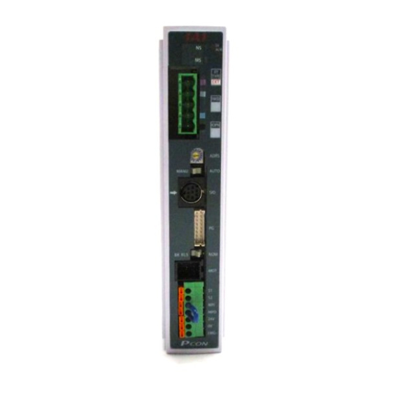
Page 27: Name And Function Of Each Part Of The Controller
NPN --- Sink type PNP --- Source type Explanation of motor drive-power cutoff circuit INT --- PCON-C/CF [Internal drive-power cutoff relay type] EXT --- PCON-CG [External drive-power cutoff relay type] Indication of model name of actuator to be connected The type name, ball screw lead length and stroke of the applicable actuator are indicated. - Page 28 Explanation of power-supply terminal block [1] PCON-C/CF [Internal drive-power cutoff relay type] Provide a contact output for the emergency-stop button on the teaching pendant. S1, S2 * Whether or not a teaching pendant is connected is determined by an internal circuit.
-
Page 29: External Dimensions
2.3 External Dimensions An external view and dimensions of the product are shown below. 5... -
Page 30: Installation Environment
Installation and Noise Elimination Pay due attention to the installation environment of the controller. 3.1 Installation Environment (1) When installing and wiring the controller, do not block the cooling ventilation holes. (Insufficient ventilation will not only prevent the controller from demonstrating its full performance, but it may also cause breakdown.) (2) Prevent foreign matter from entering the controller through the ventilation holes. -
Page 31: Installation And Noise Elimination
Separate the controller cables from high-power lines such as a cable connecting to a power circuit. (Do not bundle together the controller cables with high-power lines or place them in the same cable duct.) When extending the supplied motor cable or encoder cable, consult IAI’s Technical Support. (2) Noise sources and elimination Among the numerous noise sources, solenoid valves, magnet switches and relays are of particular concern when building a system. -
Page 32: Heat Radiation And Installation
3.4 Heat Radiation and Installation Design the control panel size, controller layout and cooling method in such a way that the temperature around the controller will not exceed 40C. Install the controller vertically on a wall, as shown below. Since cooling is provided by way of natural convection, always observe this installation direction and provide a minimum clearance of 50 mm above and below the controller to ensure sufficient natural airflows. -
Page 33: Internal Drive-Power Cutoff Relay Type (Pcon-C/Cf)
Wiring 4.1 Internal Drive-Power Cutoff Relay Type (PCON-C/CF) 4.1.1 External Connection Diagram An example of standard wiring is shown below. (Note) The encoder cable shown in the example is the standard cable. As for the robot cable, refer to 4.4.1 as the color of the cable is different. -
Page 34: Wiring
4.1.2 Wiring the Power Supply/Emergency-Stop Switch Wiring the power supply Input power supply 24 VDC (2 A max. per controller) EMG- To connect multiple controllers, provide a relay terminal block. Use a power cable satisfying the following specifications: Item Specification Single wire: 1.0 / Stranded: 0.8 mm Applicable wire length , AWG size 18, (copper wire) -
Page 35: Wiring The Power Supply/Emergency-Stop Switch
To provide an emergency-stop function for the entire system, the controller circuit is designed in such a way that a single EMG switch is able to actuate an emergency stop in all connected controllers. [Internal emergency-stop circuit] Teaching pendant PCON-C controller EMG signal Connection detection circuit Relay Input power supply (2 A max.) - Page 36 Representative connection examples are explained below. Connecting the teaching pendant directly to the controller [1] Connecting multiple controllers (8 units or less) using a single power supply Short the MPI and MPO terminals using a jumper wire. (The controller is shipped with these terminals shorted.) ...
- Page 37 [Controller 1] Teaching pendant EMG signal Connection detection circuit Relay EMG- [Controller 2] Teaching pendant Connection detection circuit Relay EMG- [Controller 3] Teaching pendant Connection detection circuit Relay EMG- [Controller 4] Teaching pendant Connection detection circuit Relay EMG-...
- Page 38 [2] Using a power supply other than the input power supply (Note) Use an auxiliary relay with a coil current of 0.1 A or less and connect a diode for coil surge absorption. control © 24V © 0V [Controller 1] Teaching pendant EMG signal Connection...
- Page 39 [3] Enabling the EMG switch on the teaching pendant for the connected axis or axes only EMG signal [Controller 1] Teaching pendant Connection detection circuit Relay EMG- [Controller 2] Teaching pendant Connection detection circuit Relay EMG- [Controller 3] Teaching pendant Connection detection circuit Relay...
- Page 40 Connecting the teaching pendant to a SIO converter Configure the contact circuit for the EMG switch on the teaching pendant using EMG1/EMG2 on the power/emergency-stop terminal block on the SIO converter. (S1/S2 on the controller’s terminal block are not used.) SIO converter Teaching pendant EMG signal...
-
Page 41: External Drive-Power Cutoff Relay Type (Pcon-Cg)
4.2 External Drive-Power Cutoff Relay Type (PCON-CG) 4.2.1 External Connection Diagram An example of standard wiring is shown below. (Note) The encoder cable shown in the example is the standard cable. As for the robot cable, refer to 4.4.1 as the color of the cable is different. Controller Connection detection circuit... -
Page 42: External Connection Diagram
4.2.2 Wiring the Power Supply/Emergency-Stop Switch Wiring the power supply Input power supply 24 VDC (2 A max. per controller) EMG- To connect multiple controllers, provide a relay terminal block. Use a power cable satisfying the following specifications: Item Specification Single wire: 1.0 / Stranded: 0.8 mm Applicable wire length , AWG size 18, (copper wire) -
Page 43: Wiring The Power Supply/Emergency-Stop Switch
Wiring the motor power cutoff relay Explained below is a safety circuit conforming to safety category 2. The user is responsible for implementing additional safety measures in the actual circuit configuration, such as providing double contactor contacts to prevent fusing. The circuit illustrated below is for reference purposes only. - Page 44 [Connection example of a multiple-axis configuration] Input power supply Connect to 24-V terminal Connect to 0-V terminal [Controller 1] [Controller 2] [Controller 3] EMG- EMG- EMG- Contactor External reset switch Safety relay unit Phoenix contact (PSR-SCP-24UC-/ESA2/4X1/1X2/B)
-
Page 45: Connecting The I/O Cables
4.3 Connecting the I/O Cables PIO pattern 0 [Standard Type] Controller end Host system <PLC> end (signal abbreviation) Upper stage Brown 1 +24 [V] Red 1 +24 [V] Orange 1 Yellow 1 Green 1 Command position 1 Blue 1 Command position 2 Purple 1 Command position 4... -
Page 46: Pio Pattern 0 [Standard Type]
PIO pattern 1 [Teaching Type] Host system <PLC> end Controller end (signal abbreviation) Upper Brown 1 stage +24 [V] Red 1 +24 [V] Orange 1 Yellow 1 Green 1 Command position 1 Blue 1 Command position 2 Purple 1 Command position 4 Gray 1 Command position 8... - Page 47 PIO pattern 2 [256-piont mode] Host system <PLC> end Controller end PIO (signal abbreviation) Upper Brown 1 stage +24 [V] Red 1 +24 [V] Orange 1 Yellow 1 Green 1 Command position 1 Blue 1 Command position 2 Purple 1 Command position 4 Gray 1 Command position 8...
-
Page 48: Pio Pattern 2 [256-Piont Mode]
PIO pattern 3 [512-piont mode] Host system <PLC> end Controller end (signal abbreviation) Upper Brown 1 stage Red 1 Orange 1 Yellow 1 Green 1 Command position 1 Blue 1 Command position 2 Purple 1 Command position 4 Gray 1 Command position 8 White 1 Command position 16... -
Page 49: Pio Pattern 3 [512-Piont Mode]
PIO pattern 4 [Solenoid valve mode 1] Host system <PLC> end Controller end (signal abbreviation) Upper Brown 1 stage Red 1 Orange 1 Yellow 1 Green 1 Direct position command 0 Blue 1 Direct position command 1 Purple 1 Direct position command 2 Gray 1 Direct position command 3... -
Page 50: Pio Pattern 4 [Solenoid Valve Mode 1]
PIO pattern 5 [Solenoid valve mode 2] Host system <PLC> end Controller end (signal abbreviation) Upper Brown 1 stage Red 1 Orange 1 Yellow 1 Green 1 Rear end move Blue 1 Front end move Purple 1 Intermediate point move Gray 1 White 1 Black 1... - Page 51 Caution: When performing a continuity check of the flat cable, pay due attention not to expand the female pins in the connector. It may cause contact failure and disable normal operation of the controller. Bulls-Eye Black 4 Terminal Block Kit Lower stage provides Brown 3...
- Page 52 Bulls-Eye Terminal Block Kit - P,A,S-Con (-CF) Controller I/O Wiring For TB with/without LED's P I/O Pattern Setting Definitions From Parameter Setting # 25 Lower Upper Wiring Wiring Wire Color 0=Standard 1=Teaching Mode 2=256 Point Mode 3=512 Point Mode 4=7-Point Mode 5=3-Point Mode Brown-1 24 Volt...
-
Page 53: Connecting The Actuator
4.4 Connecting the Actuator 4.4.1 Connecting the PCON-C/CG and Actuator Use dedicated relay cables to wire the controller and actuator. (1) RCP2 motor cable Model: CB-RCP2-MA ( indicates the cable length L. Example. 080 = 8 m) Pin layout Pin layout... - Page 54 (3) RCP3 motor/encoder integrated cable Model: CB-PCS-MPA ( indicates the cable length L. Example. 080 = 8 m) Cable model marking (Front view) Actuator end Controller end Housing: D-2100D 1-1318119-3 (Hirose) Contact: D-2 1318105-1 Signal Cable name Pin No. Pin No. name Black White...
-
Page 55: Connecting The Pcon-Cf And Actuator
4.4.2 Connecting the PCON-CF and Actuator Use dedicated relay cables to wire the controller and actuator. (1) RCP2 motor cable Model: CB-RCP2-MA ( indicates the cable length L. Example. 080 = 8 m) Pin layout Pin layout Cable model marking (Front view) (Front view) Actuator end... -
Page 56: Connecting The Communication Cable
4.5 Connecting the Communication Cable Connect the communication cable to the SIO connector. Pin assignments of the cable-end connector RS485 conversion adapter end Controller end CB-RCA-SIO*** Pin No. Signal name Cable color Cable color Pin No. Signal name Centered Brown Orange Yellow Brown/Green... -
Page 57: I/O Signal Control And Signal Functions
I/O Signal Control and Signal Functions 5.1 Interface Circuit The standard interface specification of the controller is NPN, but the PNP specification is also available as an option. To prevent confusion during wiring, the NPN and PNP specifications use the same power line configuration. -
Page 58: External Output Specifications
5.1.2 External Output Specifications Item Specification Number of output points 16 points Rated load voltage 24 VDC Maximum current 50 mA/point Residual voltage 2V or less Insulation method Photocoupler Internal circuit configuration [NPN specification] Controller P24V Load Internal circuit Each output Load External power supply... -
Page 59: Pio Patterns And Signal Assignments
5.2 PIO Patterns and Signal Assignments This controller provides six PIO pattern types to meet the needs of various applications. To select a desired type, set a corresponding value from 0 to 5 in parameter No. 25 (PIO pattern selection). The features of each PIO pattern are explained below: Parameter No. -
Page 60: Explanation Of Signal Names
5.2.1 Explanation of Signal Names The following explains the signal names, and gives a function overview of each signal. In the explanation of operation timings provided in a later section, each signal is referenced by its self- explanatory name for clarity. If necessary, however, such as when marker tubes are inserted as a termination of the flat cable, use the signal abbreviations. -
Page 61: Pio Pattern = 1: Teaching Mode [Teaching Type]
PIO pattern = 1: Teaching mode [Teaching type] Signal Category Signal name Function overview abbreviation The target position number is input. Command position A command position number must be specified by 6 ms before number the start signal (CSTR) turns ON. PC16 PC32 Operation mode... -
Page 62: Pio Pattern = 2: 256-Point Mode [256-Point Type]
PIO pattern = 2: 256-point mode [256-point type] Signal Category Signal name Function overview abbreviation The target position number is input. Command position A command position number must be specified by 6 ms before number PC16 the start signal (CSTR) turns ON. PC32 PC64 PC128... -
Page 63: Pio Pattern = 3: 512-Point Mode [512-Point Type]
PIO pattern = 3: 512-point mode [512-point type] Signal Category Signal name Function overview abbreviation The target position number is input. Command position PC16 A command position number must be specified by 6 ms before number the start signal (CSTR) turns ON. PC32 PC64 PC128... -
Page 64: Pio Pattern = 4: Solenoid Valve Mode 1 [7- Point Type]
PIO pattern = 4: Solenoid valve mode 1 [7- point type] Signal Category Signal name Function overview abbreviation Direct position The actuator will start moving to position No. 0 at a rise edge of this command 0 signal. Direct position The actuator will start moving to position No. -
Page 65: Pio Pattern = 5: Solenoid Valve Mode 2 [3-Point Type]
PIO pattern = 5: Solenoid valve mode 2 [3-point type] Signal Category Signal name Function overview abbreviation Rear end move The actuator will move toward the rear end while this signal command remains at ON level. Front end move The actuator will move toward the front end while this signal command remains at ON level. -
Page 66: Signal Assignment Table For Respective Pio Patterns
5.2.2 Signal Assignment Table for Respective PIO Patterns When creating a PLC sequence or wiring signals, assign each pin correctly by referring to the assignment table below. When “1 [Teaching type]” is selected, the meaning of each pin number will vary depending on the mode. Accordingly, also pay due attention to the mode switch timings. -
Page 67: Details Of I/O Signal Functions
5.3 Details of I/O Signal Functions An input time constant is provided for the input signals of this controller, in order to prevent malfunction due to chattering, noise, etc. Except for certain signals, switching of each input signal will be effected when the signal has been received continuously for at least 6 msec. -
Page 68: Pause (*Stp)
Pause (*STP) When this signal turns OFF while the actuator is moving, the actuator will decelerate to a stop. The remaining movement is retained and will be resumed when the signal is turned ON again. To abort the movement command, turn ON the alarm reset signal while this signal is OFF to cancel the remaining movement. -
Page 69: Brake Release (Bkrl)
Brake release (BKRL) When the actuator is equipped with a brake, you may want to forcibly release the brake in certain situations such as when starting up the system for the first time. Normally the brake release switch on the front panel of the controller is set to the “RLS”... -
Page 70: Jog (Jog+, Jog-)
Jog (JOG+, JOG-) This signal is enabled when the teaching type is selected. When the actuator is jogging (i.e., the JISL signal is OFF), it will jog toward the +/- software stroke limit upon detection of an OFF ON rise edge of this signal. If an ON ... -
Page 71: Movement To Each Position (St0 To St2) [3-Point Type]
Movement to each position (ST0 to ST2) [3-point type] Since the number of positioning points is limited to three, the actuator can be controlled just like an air cylinder. While this signal is ON, the actuator will move toward the target position. If the signal turns OFF while the actuator is moving, the actuator will decelerate to a stop. -
Page 72: Details Of Each Output Signal
5.3.2 Details of Each Output Signal Operating mode status (RMDS) The internal operating mode of the controller is output based on the AUTO/MANU selector switch on the controller and the RMOD signal received by the input port. If the selector switch is set to “AUTO” and the RMOD signal is OFF (AUTO), the controller is in the AUTO (OFF) mode. -
Page 73: Home Return Completion (Hend)
Home return completion (HEND) This signal is OFF immediately after the power is input, and turns ON in either of the following two conditions: [1] Home return operation has completed with respect to the first movement command issued with the start signal. -
Page 74: Movement Complete At Each Position (Pe0 To Pe6) [7-Point Type]
Movement complete at each position (PE0 to PE6) [7-point type] When PIO pattern is “4,” a position number (0 through 6) corresponding to each movement command will be output upon completion of positioning. Simple alarm-code output function is not provided for these signals. -
Page 75: Emergency Stop (*Emgs)
Emergency stop (*EMGS) This signal remains ON while the controller is normal, and will turn OFF if the emergency stop circuit is cut off. Program the PLC so that it will monitor this signal and implement appropriate safety measures for the entire system if the signal turns OFF. -
Page 76: Data Entry
Data Entry <Basics> To move the actuator to a specified position, a target position must be entered in the “Position” field. A target position can be specified in the absolute mode where a distance from the home is entered, or in the incremental mode where a relative travel from the current position is entered. - Page 77 Increasing the speed and acceleration/deceleration may significantly impact the actuator depending on the load mass, and the actuator characteristics also vary from one model to another. Contact IAI for the maximum limits that can be entered in your specific application.
- Page 78 “Push & hold operation” This field defines the maximum push distance after reaching the target position in push & hold operation. Consider possible mechanical variation of the load and set an appropriate positioning band that will prevent the positioning from completing before the load is contacted.
- Page 79 (9) Acceleration/deceleration This field is not used for this controller. mode The factory setting is “0.” This field defines whether the position is specified in the absolute mode (10) Incremental or incremental mode. The factory setting is “0.” 0: Absolute mode 1: Incremental mode (11) Command mode...
-
Page 80: Relationship Of Push Force At Standstill And Current-Limiting Value
6.1.1 Relationship of Push Force at Standstill and Current-Limiting Value When performing operation in the push & hold mode, enter the current-limiting value (%) in the push column of the position-data table. Determine the current-limiting value (%) from the push force to be applied to the load at standstill. The graphs below illustrate the relationship of push force at standstill and current-limiting value for each actuator type: Note:... -
Page 81: Ss8C Type
(3) SS8C type Low-speed type (Lead: 5 mm) Current-limiting value (%) Medium-speed type (Lead: 10 mm) Current-limiting value (%) High-speed type (Lead: 20 mm) Current-limiting value (%) Caution: The precision of push force at standstill is not guaranteed. The above graphs are provided for reference purposes only. -
Page 82: Rod Type
Rod type (1) RA2C type (2) RA3C type Low-speed type (Lead: 2.5 mm) Current-limiting value % Current-limiting value % Medium-speed type (Lead: 5 mm) Current-limiting value % Caution: The precision of push force at standstill is not guaranteed. The above graphs are provided for reference purposes only. -
Page 83: Ra4C Type
(3) RA4C type (4) RA6C type Low-speed type Low-speed type (Lead: 2.5 mm) (Lead: 4 mm) Current-limiting value (%) Current-limiting value (%) Medium-speed type Medium-speed type (Lead: 8 mm) (Lead: 5 mm) Current-limiting value (%) Current-limiting value (%) High-speed type High-speed type (Lead: 10 mm) (Lead: 16 mm) -
Page 84: Ra10C/W-Ra10C Type
(5) RA10C/W-RA10C type Low-speed type (Lead: 2.5 mm) Current-limiting value (%) Medium-speed type (Lead: 5 mm) Current-limiting value (%) High-speed type (Lead: 10 mm) Current-limiting value (%) Caution: The precision of push force at standstill is not guaranteed. The above graphs are provided for reference purposes only. -
Page 85: Explanation Of Modes
6.2 Explanation of Modes 6.2.1 Positioning Mode Push = 0 The actuator moves to the target position set in the “Position” field of the position table. Speed The position complete signal turns ON here. Target position Moving distance Time Positioning band 6.2.2 Push &... - Page 86 (2) Load was not contacted (missed) If the actuator does not still contact the load after having moved the distance specified in the “Positioning band” field, the position complete signal will not turn ON. Therefore, include timeout check processing in the sequence circuit on the PLC side. ...
-
Page 87: Torque Check Function In Push & Hold Operation
(4) Positioning band was entered with a wrong sign Take note that if a value with a wrong sign is set in the “Positioning band” field of the position table, the operation will deviate by a distance corresponding to “positioning band x 2,” as shown below. Speed Moving distance... - Page 88 This function is available only with the PCON-CF controller. (It cannot be used with the PCON-C or PCON-CG controller.) If the actuator contacts the load before reaching the target position, a servo error alarm will generate. Pay due attention to the relationship of the target position and the load Warning position.
-
Page 89: Speed Change During Movement
“reduce the tact time when the load mass is significantly smaller than the rated load capacity.” If you want to use acceleration/deceleration settings greater than the rating, consult IAI beforehand because it may affect the life of the actuator. -
Page 90: Pause
6.2.6 Pause The actuator can be paused during movement using an external input signal (*STP). The pause signal uses the contact b logic (always ON) to ensure safety. Turning the *STP signal OFF causes the actuator to decelerate to a stop. When *STP is turned ON subsequently, the actuator will resume the remaining movement. -
Page 91: Home Return
6.2.8 Home Return After the power is turned on, home return must be performed to establish the home position. The method of home return varies depending on the PIO pattern. When a dedicated input is used [PIO pattern 5] Home return is performed using the home return (HOME) input. -
Page 92: Overview Of Teaching Type
6.2.9 Overview of Teaching Type Depending on your system, it may be desirable to be able to use a touch panel, etc., to perform jogging operation or write the current position to the “Position” field of the position table, without using a PC or teaching pendant. -
Page 93: Overview Of 7-Point Type
6.2.10 Overview of 7-point Type The number of positioning points is kept small, or specifically to seven or less. This type assumes simple applications where the PLC ladder sequence only requires a simple circuit configuration. I/O signals provide separate command inputs and movement complete outputs for respective position numbers. - Page 94 [2] 64-point type Command position 1 input (PC1) Command position 2 input (PC2) “5” is indicated by a binary code. Command position 4 input (PC4) * All other command position inputs (PC8, PC16 and PC32) turn OFF. At least 6 msec of delay time is needed (ensured by a timer setting on the PLC side).
-
Page 95: Overview Of 3-Point Type
6.2.11 Overview of 3-point Type This type provides a control method adjusted to that of an air cylinder by assuming that the controller is used as an air cylinder. The key differences between this controller and an air cylinder are summarized in the table below. Program appropriate controls by referring to this table. - Page 96 Item Air cylinder RCP2 Position Determined by an Immediately after the power is turned on, the controller cannot check upon external detection identify the current position because the mechanical coordinates power ON sensor, such as a reed have been lost. switch.
-
Page 97: Notes On The Robo Gripper
6.3 Notes on the ROBO Gripper (1) Finger operation [1] Definition of position The specified stroke of the 2-finger type indicates the sum of travel distances of both fingers. In other words, the travel distance of one finger is one half the specified stroke. A position you specify defines the distance traveled by one finger from the home position in the closing direction. - Page 98 (2) Removing the gripped load This gripper is designed to maintain the load-gripping force via a self-lock mechanism even when the servo is turned OFF or the controller power is cut off. If the gripped load must be removed while the power is cut off, do so by turning the open/close screw or removing the finger attachment on one side.
-
Page 99: Power-Saving Modes At Standby Positions
6.4 Power-saving Modes at Standby Positions One general feature of pulse motors is that their holding current in standstill state is greater than AC servo motors. Therefore, this product provides energy-saving modes to reduce power consumption in situations where the actuator remains standstill for a long period at a standby position. Use these modes after confirming that they will not present problems to any part of your system. - Page 100 Full servo control mode The pulse motor is servo-controlled to reduce the holding current. Although the exact degree of current reduction varies depending on the actuator model, load condition, etc., the holding current decreases to approx. 1/2 to 1/4. Since the servo remains on, position deviation will not occur.
- Page 101 Movement command Automatic servo-off mode (A green LED blinks.) Servo status Servo on Actuator movement Target position T: Delay time (seconds) after positioning is completed until the servo turns off Position complete signal (parameter No. 39 = 0) Position complete signal (parameter No.
-
Page 102: Using A Rotary Actuator In Multi-Rotation Specification
Pay attention to the setting of the PIO pattern parameter for the controllers specified below. Each controller does not support relative coordination specification in the PIO pattern specified. [1] PCON-C/CG: PIO pattern = 5 (User parameter No. 25) [2] PCON-CY: PIO pattern = 0 (User parameter No. -
Page 103: Operation
Operation <Practical Steps> 7.1 How to Start 7.1.1 Timings after Power On Procedure after initial startup until actuator adjustment [1] Connect the motor relay cable to the MOT connector and encoder relay connector to the PG connector. [2] Connect the supplied flat cable to the PIO connector (for connection between the host PLC and I/O unit). - Page 104 [10] Perform home return. Overview of operation on the teaching pendant On the RCM-T, select the “Edit/Teach” screen, bring the cursor to “*Home” in the sub display area, and then press the Return key. On the RCM-E, select the “Teach/Play” screen, scroll until “*Home Return” is displayed, and then press the Return key.
-
Page 105: Procedure Of Normal Operation
Procedure of Normal Operation The operating procedure in normal condition is specified below: [1] Reset the emergency stop or enable the supply of motor drive power. [2] Supply the 24-VDC I/O power. [3] Supply the 24-VDC controller power. * If the monitor LED [SV/ALM] on the front panel illuminates for 2 seconds initially and then turns off, the controller is normal. - Page 106 Emergency stop not actuated (motor drive power supplied) Safety circuit condition Supply of 24-VDC I/O power Supply of 24-VDC controller power * Be sure to set the switch to the “AUTO” side. Mode selector switch * If this output signal is OFF, I/O signal communication with the PLC is enabled. Operation mode status output (RMDS) Pause input...
-
Page 107: Position Table And Parameter Settings Required For Operation
If the actuator cannot be moved by hand, one possible solution is to change the setting of parameter No. 28 (Default direction of excited-phase signal detection). If you wish to change this parameter, consult IAI beforehand. 7.1.2 Position Table and Parameter Settings Required for Operation ... -
Page 108: Full-Scale Operation
Full-scale operation This product provides energy-saving modes to reduce power consumption in situations where the actuator remains standstill for a long period at a standby position. You can also select the status of position complete signal to be applied if the servo turns off or “position deviation”... -
Page 109: Home Return Operation
7.2 Home Return Operation 7.2.1 Method Using the HOME Input Signal (PIO Pattern = 0 to 4) Since the home return signal (HOME) is provided in PIO patterns 0 to 4, perform home return using this signal. When the home return signal (HOME) turns ON, the actuator starts moving toward the mechanical end on the home side. - Page 110 (Note) If the home is not yet established immediately after the power has been turned on, directly inputting the command position signal and start signal without inputting the home return signal (HOME) first will cause the actuator to perform home return operation and then move to the target position.
-
Page 111: Method Used When No Home Input Signal Is Available (Pio Pattern = 5)
7.2.2 Method Used When No HOME Input Signal Is Available (PIO Pattern = 5) Since no home return signal (HOME) is available in PIO pattern 5, input the rear end move command (ST0) first to perform home return. When the rear end movement command (ST0) turns ON, the actuator starts moving toward the mechanical end on the home side. -
Page 112: Positioning Mode (Back And Forth Movement Between Two Points)
7.3 Positioning Mode (Back and Forth Movement between Two Points) Example of use in operation) The actuator moves back and forth between two positions. The position 250 mm from the home is set as position 1, and the position 100 mm from the home is set as position 2. - Page 113 Position table (Field(s) within thick line must be entered.) Position Speed Acceleration Deceleration Push Positioning [mm] [mm/s] band [mm] 250.00 200.00 0.30 0.30 0.10 100.00 100.00 0.30 0.30 0.10 Command position Position 1 Position 2 Position 1 Start Position complete Moving Completed position Position 1...
-
Page 114: Push & Hold Mode
7.4 Push & Hold Mode Example of use in operation) The actuator is caused to move back and forth in the push & hold mode and positioning mode. The position 280 mm from the home is set as position 1, and the position 40 mm from the home is set as position 2. - Page 115 Position table (Field(s) within thick line must be entered.) Position Speed Acceleration Deceleration Push Positioning [mm] [mm/s] band [mm] 280.00 200.00 0.30 0.30 15.00 40.00 100.00 0.30 0.30 0.10 Command position Position 1 Position 2 Position 1 Start Position complete Moving Note Note...
-
Page 116: Return Action After Push & Hold By Relative Coordinate Specification
7.4.1 Return Action after Push & Hold by Relative Coordinate Specification Positioning mode The reference position is the target position for the position number used in the applicable push & hold operation. In the aforementioned example, the actuator moves to the 240-mm position if position No. 2 is set to -40 mm in the incremental mode (280 –... -
Page 117: Speed Change During Movement
7.5 Speed Change during Movement Example of use in operation) The actuator speed is reduced at a certain point during movement. The position 150 mm from the home is set as position 1, and the position 200 mm from the home is set as position 2. The actuator is initially located between the home and position 1. - Page 118 Position table (Field(s) within thick line must be entered.) Position Speed Acceleration Deceleration Push Positioning [mm] [mm/s] band [mm] 150.00 200.00 0.30 0.30 10.00 200.00 100.00 0.30 0.30 0.10 Position 1 Position 2 Command position Note Note Start Position complete Position 2 Completed position Position 1...
-
Page 119: Operation At Different Acceleration And Deceleration Settings
7.6 Operation at Different Acceleration and Deceleration Settings Example of use in operation) Positioning is performed to the position 150 mm from the home (position 1) at a speed of 200 mm/sec. The acceleration is 0.3 G and the deceleration is 0.1 G. Method) Set 0.3 [G] in the “Acceleration”... - Page 120 Position table (Field(s) within thick line must be entered.) Position Speed Acceleration Deceleration Push Positioning [mm] [mm/s] band [mm] 150.00 200.00 0.30 0.10 0.10 Command position Position 1 Start Position complete Position 1 Completed position Moving Speed Positioning band Actuator movement Deceleration 0.1 G Acceleration 0.3 G T1: 6 msec or more;...
-
Page 121: Pause
7.7 Pause Example of use in operation) Pause the actuator during movement. [Effective in PIO pattern = 0 to 4] Method) Use the pause input. Controller Reference flow Select/enter a desired command position. Category Signal name [5][2] Start Start input ON Command position 1 Command position 2 Movement to the selected position... - Page 122 Command position Start Note Position complete Completed position Pause Moving 4 msec or less Speed Actuator movement Deceleration to a stop Start of remaining movement T1: 6 msec or more; time after selecting/entering a command position until the start input turns ON (The scan time of the host controller must be considered.) Caution: When the start signal turns ON, the position complete output will turn OFF and the moving output will turn ON.
-
Page 123: Zone Signal Output
7.8 Zone Signal Output Two types of zone output signals are available: zone output (ZONE1) and position zone output (PZONE). The boundaries defining the signal ON range are set differently for each zone output. [1] Zone output (ZONE1) --- Set by parameter No. 1/No. 2. [2] Position zone output (PZONE) --- Set in the “Zone boundary-“... - Page 124 Controller Reference flow Category Signal name Select/enter a desired command position. [5] [2] Start Start input ON Command position 1 Input Movement to the selected position starts. Completed position OFF Command position 32 Completed position 1 Position complete output OFF Moving output ON Completed position 32 Output...
- Page 125 Command position Start Note Position complete Completed position Zone Moving Speed Actuator movement 0 mm 40 mm 120 mm 150 mm 6 msec or more; time after selecting/entering a command position until the start input turns ON (The scan time of the host controller must be considered.) Caution: When the start signal turns ON, the position complete output will turn OFF and the moving output will turn ON.
-
Page 126: Incremental Moves
7.9 Incremental Moves Example of use in operation) Move the actuator from the home to the 30-mm position by issuing an absolute position command (position No. 1), and thereafter move the actuator continuously at a 10-mm pitch until the final position of 200 mm is reached. - Page 127 Position table (Field(s) within thick line must be entered.) Positioning Speed Position Zone + Zone - band Incremental [mm/ss] [mm] [mm] [mm] [mm] 30.00 100.00 0.10 Incremental 10.00 20.00 0.10 29.50 190.50 feed * On the teaching pendant screen, this sign indicates that the position is specified in the incremental mode.
-
Page 128: Judgment Method Of End Position
7.9.1 Judgment Method of End Position Although completion judgment is based on the applicable count managed by the PLC, the zone output signal can be used additionally to double-check the completion of movement. Program the PLC so that the ON/OFF status of the zone output signal is checked when positioning is completed, and if the signal is OFF, the applicable position will be determined as the last load position. -
Page 129: Notes On Incremental Mode
7.9.2 Notes on Incremental Mode If an operation command is issued based on relative coordinate specification while the actuator is moving (in the normal positioning mode or push & hold mode), how the actuator will operate varies depending on whether or not push action is specified in the operation command by relative coordinate specification, as explained below. - Page 130 [2] When a relative coordinate operation command is specified while the actuator is moving in the push & hold mode The following explains how the actuator will move if an incremental position number is selected and input and then a start signal is input while the actuator is moving in the push & hold mode. Example) If the start signal for movement to position 2 is input while the actuator is moving to position 1, the actuator will move to the position corresponding to the target position set in the position 1 data plus the incremental distance.
- Page 131 (2) When the relative coordinate operation command specifies an operation in the push & hold mode Example) If a position 2 command is input followed by a start signal while the actuator is moving to position 1, a new target position will be set by adding the incremental distance to the current position where the start input was received.
-
Page 132: Jogging/Teaching Using Pio
7.10 Jogging/Teaching Using PIO If the teaching type is selected, you can jog the actuator via operation from the PLC. You can also write the current actuator position to the “Position” field of the position table under a specified position number via operation from the PLC. If the actuator position is written to a blank “Position”... - Page 133 Jogging/teaching timing Operation mode Current operation mode Manual operation switching +Jog -Jog Position 1 Command position Current-position write Write completion T1: 20 msec or more; time after the current-position write input is turned ON until writing of the current position is started When the operation mode (MODE) input is turned ON, the current operation mode (MODES) output will turn ON and the teaching mode permitting PIO teaching will become effective.
-
Page 134: Operation In 7-Point Type
7.11 Operation in 7-point Type Separate movement command inputs are provided for the target positions for position Nos. 0 to 6, so simply turn ON the input signal corresponding to the position you wish to move the actuator to, and the actuator will start moving. - Page 135 Direct position command 0 input (ST0) Direct position command 1 input (ST1) Direct position command 2 input (ST2) Movement complete 0 output (PE0) Movement complete 1 output (PE1) Movement complete 2 output (PE2) Actuator movement Position No. 0 (5 mm) Position No.
- Page 136 The movement command input operates in two modes. You can select the operation condition of the movement command input (ST0 to ST6) in parameter No. 27. The factory setting is “0: [Level mode].” Description of the movement command input Setting Level mode: The actuator starts moving when the input signal turns ON.
- Page 137 Handling of the pause (*STP) signal This signal is a contact B signal, meaning that it must remain ON while the actuator is moving. If the pause signal turns OFF while the actuator is moving, the actuator will decelerate to a stop. The actuator will start moving when the signal turns ON again.
-
Page 138: Operation In 3-Point Type
7.12 Operation in 3-point Type After the power has been turned on, input the rear end move command first to complete home return, and then perform continuous operation. Refer to 7.2.2, “Method Used When No HOME Input Signal Is Available.” Example of use in operation) How to move the actuator from the rear end to the front end is explained. - Page 139 Meaning of position detected output signals (LS0, LS1, LS2) These signals are handled in the same manner as limit switches (LSs), and turn ON when the following conditions are met: [1] The home return complete output signal (HEND) is ON. [2] The current position is within the positioning band from each target position in the positive or negative direction.
- Page 140 Speed change during movement If the load is made of soft material or is a bottle or otherwise topples easily due to its shape, one of the following two methods can be used to prevent the load from receiving vibration or impact when it stops: [1] Reduce the deceleration to make the deceleration curve gradual.
- Page 141 Pause during movement Since move commands are based on level mode, the actuator continues to move while a move command is ON. Once the move command turns OFF, the actuator will decelerate to a stop and complete the operation. Therefore, turn OFF the move command if the actuator must be stopped temporarily as a low-degree safety measure.
-
Page 142: Parameters
Parameters 8.1 Parameter Table Category: a: Parameter relating to the actuator stroke range b: Parameter relating to the actuator operating characteristics c: Parameter relating to the external interface d: Servo gain adjustment Category Symbol Name Unit Default factory setting ZONM Zone boundary 1+ Effective actuator length ZONL Zone boundary 1–... - Page 143 No. Category Symbol Name Unit Default factory setting Operating-mode input disable selection FPIO 0 [Enable] [0: Enable / 1: Disable] ENBL Enable function [0: Enable/1: Disable] 1 [Disable] Polarity of home check sensor input Set individually in accordance with the [0: Contact a / 1: Contact b] actuator characteristics.
-
Page 144: Detail Explanation Of Parameters
8.2 Detail Explanation of Parameters If a parameter has been changed, always restart the controller using a software reset command or by reconnecting the power. 8.2.1 Parameters Relating to the Actuator Stroke Range Soft limit (No.3/4 LIMM/LIML) Set the soft limit in the positive direction in parameter No. 3, and that in the negative direction in parameter No. -
Page 145: Zone Boundary
Zone boundary (1: No.1/2 ZONM/ZONL 2: No.23/24 ZNM2/ZNL2) These parameters set the zone within which the zone output signal (ZONE1) turns ON when the selected PIO pattern is “0” (standard type), “4” (7-point type) or “5” (3-point type). The zone output signal turns ON when the current position is between the negative-side boundary and positive-side boundary. -
Page 146: Home Return Direction
Home return direction (No.5 ORG) Unless specified by the user, the home return direction is set to the motor direction at the factory. Should a need arise to change the home direction after the actuator has been assembled into your system, reverse the setting in parameter No. -
Page 147: Default Acceleration/Deceleration
Default acceleration/deceleration (No.9 ACMD) The factory setting is the rated acceleration/deceleration of the actuator. When a target position is written to an unregistered position table or the current position is read in the teaching mode, the setting in this parameter will be used as the acceleration/deceleration data for the applicable position number. -
Page 148: Default Direction Of Excited-Phase Signal Detectio
No. 29. If you wish to change this parameter, contact IAI beforehand. Safety speed (No.35 SAFV) This parameter defines the feed speed to be applied during manual operation. -
Page 149: Automatic Servo-Off Delay Time
Automatic servo-off delay time (No.36 ASO1/No.37 ASO2/No.38 ASO3) This parameter defines the delay time after the positioning is completed until the servo turns off automatically, when the “Standstill mode” field of the position table is set to “1,” “2” or “3” (automatic servo- off control enabled) or parameter No. -
Page 150: Push Speed
Push speed (No.34 PSHV) This parameter defines the push speed to be applied after the actuator reaches the target position in push & hold operation. Before the shipment, this parameter has been set to the default value selected in accordance with the characteristics of the actuator. -
Page 151: Enable Function
Enable function (No.42 FDIO4) Whether to enable or disable the deadman switch function on an ANSI-type teaching pendant is defined by parameter No. 42. * An ANSI-type teaching pendant will be developed in the future. Setting Enable (Use) Disable (Do not use) The factory setting is “1 [Disable].”... -
Page 152: Torque Check Range
Torque check range (No.51 TRQZ) This parameter sets whether or not to use the check range when determining if the threshold has been exceeded. The default value is “0,” i.e., to enable the check range. Setting Enable (Use the check range to make judgment) Disable (Do not use the check range to make judgment) ... -
Page 153: Absolute Unit
If the actuator is moved in the order to positions 1 2 3 4, the actuator will operate differently depending on whether or not shortcut is selected, as explained below. When shortcut is not selected Point No. 1 Point No. -
Page 154: Parameters Relating To The External Interface
8.2.3 Parameters Relating to the External Interface PIO pattern selection (No.25 IOPN) Select the PIO operation pattern in parameter No. 25. This setting forms the basis of operation, so be sure to set this parameter at the beginning. The factory setting is “0 [Standard type].” Parameter No. -
Page 155: Movement Command Type
Movement command type (No.27 FPIO) When the PIO pattern is set to “7-point type,” define the operation condition of the movement command input (ST0 to ST6) in parameter No. 27. The factory setting is “0 [Level mode].” Description of the movement command input Setting Level mode: The actuator starts moving when the input signal turns ON. -
Page 156: Pause Input Disable Selection
Pause input disable selection (No.15 FPIO) Parameter No. 15 defines whether the pause input signal is disabled or enabled. Setting Enable (use) Disable (do not use) the signal The factory setting is “0 [Enable].” Servo ON input disable selection (No.21 FPIO) Parameter No. -
Page 157: Output Mode Of Position Complete Signal
Output mode of position complete signal (No.39 FPIO) This parameter is effective when any PIO pattern other than “5” [3-point type] is selected. It defines the status of completed position number signals [PM1 to PM256], movement complete signals at respective positions [PE0 to PE6] and position complete signal [PEND] to be applied if the servo turns off or “position deviation”... -
Page 158: Silent Interval Multiplier
Silent interval multiplier (No.45 SIVM) This parameter is not used for this controller. It is applied to controllers of RS485 serial communication type. If specified, this parameter defines the multiplier to be applied to the silent interval time for delimiter judgment in the RTU mode. -
Page 159: Servo Gain Adjustment
In particular, custom types (having a longer ball screw lead or stroke than standard types) are more vulnerable to vibration and noise due to external conditions. In these circumstances, the following parameters must be changed. Contact IAI for details. Servo gain number (No.7 PLG0) Parameter No. -
Page 160: Speed Loop Integral Gain
Speed loop integral gain (No.32 VLPT) Parameter No. Unit Input range Default Set individually in accordance with the 1 ~ 217270 actuator characteristics. This parameter determines the response when a speed control loop is used. Increasing the set value lowers the response with respect to the speed command, while also decreasing the reactive force that generates upon load change. -
Page 161: Pc/Teaching Pendant Connection Method In Multi-Axis Configurations
PC/Teaching Pendant Connection Method in Multi-axis Configurations This section explains the method to permanently connect a PC/teaching pendant in configurations consisting of multiple axes, so that the PC/teaching pendant connector need not be removed/inserted each time. The connector is connected to a SIO converter, and the SIO converter sends/receives data to/from each controller via RS485 serial communication. -
Page 162: Sio Converter (Optional)
9.2 SIO Converter (Optional) This unit is a RS232C-RS485 converter. When multiple controllers are linked, you can connect a teaching pendant to the mini DIN 8-pin connector to move all axes together or edit the parameters of all axes at once. ... - Page 163 [4] D-sub, 9-pin connector (RS232C) A connection port with a PLC’s communication module. It can also be connected to a PC. For the communication cable, use the RS232C cross cable specified below. [5] Mini DIN, 8-pin connector (RS485) A connection port with a teaching pendant or PC. For the communication cable, use the cable (equipped with a RS232C/RS485 converter) that comes with the PC software (RCM-101-MW).
-
Page 164: Address Switch
9.3 Address Switch Set an address (0 to 15) as a hexadecimal (0 to F) using the ADRS switch on the front panel of each controller to define the slave number for the controller. Assign “0” to the controller nearest the host, and then assign 1, 2, 3, …, E and F to the remaining controllers in the direction of moving away from the host. -
Page 165: Detail Connection Diagram
9.5 Detail Connection Diagram Two-paired shielded cable Recommended brand: Four-way junction (AMP: 5-1473574-4) SIO converter Taiyo Electric Wire & Cable HK-SB/20276XL 2PX22AWG EMG2 EMG1 E-Con connector (AMP: 4-1473562-4) Housing color: Green Controller link cable CB-RCB-CTL002 Yellow Yellow Orange Orange Blue Blue Controller 2 Controller 1... -
Page 166: Troubleshooting
Check the serial numbers of the controller and actuator. k. Analyze the cause. l. Take action. Please check items a through j before contacting IAI. (Reference) Changes in status indicator lamps and *ALM output signal in respective conditions Emergency stop... -
Page 167: Alarm Level Classification
Caution: Reset each alarm after identifying and removing the cause of the alarm. If the cause of the alarm cannot be removed or the alarm still persists after the cause has been removed, contact IAI. If the same error occurs again after resetting the alarm, it means that the cause of the... -
Page 168: Alarm Description Output Using Pio
10.3 Alarm Description Output Using PIO In PIO patterns 0 to 3 (64 to 512-point positioning type), alarm information can be output using the ports for completed position output signals (four bits of PM1 to PM8) so that when an alarm occurs, the nature of the alarm can be identified on the PLC side. -
Page 169: Alarm Description And Cause/Action
Input a SON signal to turn the servo ON (the SV signal or PEND signal should turn ON). If this error occurred when parameter No. 21 was set to “Disable,” contact IAI. Position movement Cause: A position movement command was input when home return was not yet command before home completed. - Page 170 [1] The slide resistance of the actuator is high in some location. [2] The load increased due to momentary application of external force. Action: Check the assembly condition of mechanical parts for any abnormality. If the actuator itself is suspected as the cause, please contact IAI.
- Page 171 Cause: [1] The 24-V input power-supply voltage is high. [2] A faulty part inside the controller. Action: Check the input power-supply voltage. If the voltage is normal, please contact IAI. 0CA Overheating This error indicates that the temperature around the power transistor in the controller is excessively high (95C or above).
- Page 172 Code Error name Cause/Action 0D9 Software stroke limit Cause: [1] The actuator installed vertically overshot and exceeded a overtravel error software stroke limit due to a large load or high deceleration setting when the target position was set to a point near the software stroke limit.
- Page 173 (The nominal rewrite limit of the nonvolatile memory is around 100,000 times.) Action: If the alarm generates again after reconnecting the power, please contact IAI. 0F6 Nonvolatile memory This error indicates that response is not received within the specified time write timeout after data was written to the nonvolatile memory.
-
Page 174: Cold-Start Level Alarms
[5] If the load is normal, cut off the power and move the actuator by hand to check the slide resistance. If the actuator is suspected to be the cause, please contact IAI. 0E5 Encoder reception Cause:... - Page 175 This error indicates that the two do not match. Cause: The parameter was not entered correctly or the correct board was not assembled. Action: Should this error occur, please contact IAI. 0F8 Damaged nonvolatile Abnormal data was detected during the nonvolatile memory check after memory starting.
-
Page 176: Messages Displayed During Operation Using The Teaching Pendant
10.5 Messages Displayed during Operation Using the Teaching Pendant This section explains the warning messages that may be displayed during operation using the teaching pendant. Code Message name Description Invalid data An inappropriate value was entered in a parameter. (Example) 9601 was entered as the serial communication speed by mistake. - Page 177 This message indicates that an indeterminate WRITE address error occurred in the serial communication with the controller. These conditions do not occur in normal operation. Should they occur, record the entire error list before cutting off the power for use in the cause investigation. Also contact IAI.
- Page 178 [3] Supply power after connecting the link cable between the converter and controller. [4] Make sure the ADRS switch settings are not duplicated. If the message is still displayed after taking the above actions, please contact IAI.
-
Page 179: Specific Problems
[1] Contact failure of the flat cable [2] Faulty controller Check the servo ON signal (SON) on the I/O monitor screen of the PC or teaching pendant. If the signal is input, probably the controller is faulty. Please contact IAI. -
Page 180: Home Return Ends In The Middle In A Vertical Application
[2] Loosen the fixing bolts and check if the slider moves smoothly. If the slider moves smoothly, review the affixing method and bolt tightening condition. [3] If the slide resistance of the actuator itself is large, please contact IAI. Noise occurs during downward movements in a vertical application. -
Page 181: A Servo Error Occurred While The Actuator Was Moving (Robo Gripper)
A servo error occurred while the actuator was moving (ROBO Gripper). Cause: The load was not positioned properly and contacted the finger attachment in the positioning mode. Action: Adjust the starting position of push action and the thickness of finger attachment (including buffer material) by considering a possible offset of load position, so that the load can be clamped properly in the push &... -
Page 182: Abnormal Operation Results When The Servo Is Turned On After The Power On
If the load is contacting any surrounding part, provide a clearance of 1 mm or more from the applicable part. If the checks in [1] and [2] did not find any problem, please contact IAI. The SV lamp blinks. -
Page 183: Appendix
Appendix * Appendix List of Supported Actuator Specifications Slider, ball screw drive Load capacity (Note 2) Rated acceleration Stroke (mm) and maximum speed (mm/sec) (Note 1) Horizontal Vertical Horizontal Vertical Model (Note 1) The figure in the elongated circle indicates the maximum speed for each stroke. - Page 184 Appendix Rod type Rated acceleration Load capacity (Note 2) Stroke (mm) and maximum speed (mm/sec) (Note 1) Horizontal Vertical Horizontal Vertical Model (Note 1) The figure in the elongated circle indicates the maximum speed for each stroke The figure in parentheses applies to vertical operation. (Note 2) The load capacity is based on actuator operation at the rated acceleration.
- Page 185 Appendix Gripper Maximum Rated Type Stroke Maximum speed Lead gripping force acceleration RCP2-GRS-I-PM-1-10-P1 10 mm (5 mm per side) 21 N 33.3 mm/s (one side) 1.0 mm 0.3 G RCP2-GRM-I-PM-1-14-P1 14 mm (7 mm per side) 80 N 36.7 mm/s (one side) 1.1 mm 0.3 G RCP2-GR3SS-I-PM-30-10-P1...
- Page 186 Appendix Slider type Rated acceleration Load capacity (Note 2) Stroke (mm) and maximum speed (mm/sec) (Note 1) Model Horizontal Vertical Horizontal Vertical Table type Rated acceleration Load capacity (Note 2) Stroke (mm) and maximum speed (mm/sec) (Note 1) Model Horizontal Vertical...
- Page 187 Appendix Correlation diagram of speed and load capacity for the slider type (motor-straight type) Horizontal installation Vertical installation Speed (mm/sec) Speed (mm/sec) Speed (mm/sec) Speed (mm/sec) Speed (mm/sec) Speed (mm/sec) (Note) In the above graphs, the number after the type code indicates the lead.
- Page 188 Appendix Correlation diagram of speed and load capacity for the slider type (motor-reversing type) Horizontal installation Vertical installation Speed (mm/sec) Speed (mm/sec) Speed (mm/sec) Speed (mm/sec) Speed (mm/sec) Speed (mm/sec) (Note) In the above graphs, the number after the type code indicates the lead.
- Page 189 Appendix Correlation diagram of speed and load capacity for the standard rod type Horizontal installation (Note 1) Vertical installation Speed (mm/sec) Speed (mm/sec) Speed (mm/sec) Speed (mm/sec) Speed (mm/sec) Speed (mm/sec) (Note) In the above graphs, the number after the type code indicates the lead. (Note 1) The figures for horizontal installation assume use of an external guide.
- Page 190 Appendix Correlation diagram of speed and load capacity for the single-guide type Horizontal installation Vertical installation Speed (mm/sec) Speed (mm/sec) Speed (mm/sec) Speed (mm/sec) Speed (mm/sec) Speed (mm/sec) (Note) In the above graphs, the number after the type code indicates the lead.
- Page 191 Appendix Correlation diagram of speed and load capacity for the double-guide type Horizontal installation Vertical installation Speed (mm/sec) Speed (mm/sec) Speed (mm/sec) Speed (mm/sec) Speed (mm/sec) Speed (mm/sec) (Note) In the above graphs, the number after the type code indicates the lead.
- Page 192 Appendix Correlation diagram of speed and load capacity for the dustproof/splash-proof type Horizontal installation (Note 1) Vertical installation (Note 2) Speed (mm/sec) Speed (mm/sec) Speed (mm/sec) Speed (mm/sec) Speed (mm/sec) Speed (mm/sec) (Note) In the above graphs, the number after the type code indicates the lead. (Note 1) The figures for horizontal installation assume use of an external guide.
- Page 193 Appendix Correlation diagram of speed and load capacity for the high-thrust type Horizontal installation Vertical installation Speed (mm/sec) Speed (mm/sec) Speed (mm/sec) Speed (mm/sec) Speed (mm/sec) Speed (mm/sec)
- Page 194 Appendix Correlation diagram of speed and load capacity for the RCP3 slider type Horizontal installation Vertical installation Lead 2 Lead 4 Lead 2 Lead 4 Lead 6 Lead 6 Speed (mm/sec) Speed (mm/sec) Lead 2.5 Lead 5 Lead 2.5 Lead 10 Lead 5 Lead 10...
- Page 195 Appendix Correlation diagram of speed and load capacity for the RCP3 table type Horizontal installation Vertical installation Lead 2.5 Lead 2.5 Lead 5 Lead 5 Lead 10 Lead 10 Speed (mm/sec) Speed (mm/sec) Lead 3 Lead 12 Lead 6 Lead 3 Lead 6 Lead 12...
-
Page 196: Fault Check And Replacement Of The Cooling Fan
Appendix Fault check and replacement of the cooling fan A cooling fan is installed in the large-capacity type (PCON-CF). To check if the fan is faulty, or when replacing the fan, follow the procedure below: Unplug all connectors and wires connected to the controller, and take out the controller. Remove all cables except for the MPI/MPO jumper wire. - Page 197 Appendix Check if the fan is normal. Check method: Connect the power cable to the 24-V and 0-V terminals on the power-supply terminal block. Turn on the power to check if the fan operates. If the fan is normal, it should operate for approx. 2 seconds.
-
Page 198: Example Of Basic Pcon Positioning Sequence
Appendix Example of Basic PCON Positioning Sequence Given below is an example of basic sequence for creating a positioning sequence using the PCON. indicates PIO signals of the controller. (Completed-position decoding circuit) Position complete PEND Waiting for the completed Timer1 position to be read (PLC scan time or Completed position codes... - Page 199 Appendix (Positioning circuit for position 2) Positioning start request to position 2 Positioning start pulse to position 2 Positioning start request to position 2 Auxiliary positioning start pulse to position 2 Current positioning completed position Auxiliary positioning start for position 2 PEND Start check for position 2...
- Page 200 Appendix Command position 1 Position 3 set signal Position 5 set signal Command position 2 Position 3 set signal Position 6 set signal Command position 4 Command position 8 (Start signal circuit) Timer 2 Waiting for start 5 msec or more (Must be longer than the...
-
Page 201: Recording Of Parameters
Appendix Recording of Parameters Recorded date: Category: a: Parameter relating to the actuator stroke range b: Parameter relating to the actuator operating characteristics c: Parameter relating to the external interface d: Servo gain adjustment Category Name Unit Recorded data Zone boundary 1+ Zone boundary 1–... - Page 202 Appendix Category Name Unit Recorded data Operating-mode input disable selection [0: Enable / 1: Disable] Enable function [0: Enable / 1: Disable] Polarity of home check sensor input [0: Contact a / 1: Contact b] Silent interval multiplier Speed override PIO jog speed mm/sec PIO inching distance...
- Page 205 Ober der Röth 4, D-65824 Schwalbach am Taunus, Germany TEL 06196-88950 FAX 06196-889524 The information contained in this document is subject to change without notice for the purpose of product improvement. Copyright 2009. Oct. IAI Corporation. All rights reserved.
Need help?
Do you have a question about the PCON-C and is the answer not in the manual?
Questions and answers