Table of Contents
Advertisement
Quick Links
Download this manual
See also:
User Manual
Advertisement
Chapters
Table of Contents

Related Manuals for Keithley 6485


Summary of Contents for Keithley 6485
- Page 1 Model 6485 Picoammeter Instruction Manual A G R E A T E R M E A S U R E O F C O N F I D E N C E...
- Page 2 WARRANTY Keithley Instruments, Inc. warrants this product to be free from defects in material and workmanship for a period of 1 year from date of shipment. Keithley Instruments, Inc. warrants the following items for 90 days from the date of shipment: probes, cables, rechargeable batteries, diskettes, and documentation.
- Page 3 Model 6485 Picoammeter Instruction Manual ©2001, Keithley Instruments, Inc. All rights reserved. Cleveland, Ohio, U.S.A. First Printing, November 2001 Document Number: 6485-901-01 Rev. A...
- Page 4 Revision A (Document number 6485-901-01) ............November 2001 All Keithley product names are trademarks or registered trademarks of Keithley Instruments, Inc. Other brand names are trademarks or registered trademarks of their respective holders.
- Page 5 Keithley products are designed for use with electrical signals that are rated Installation Category I and Installation Category II, as described in the International Electrotechnical Commission (IEC) Standard IEC 60664. Most measurement, control, and data I/O signals are Installation Category I and must not be directly connected to mains voltage or to voltage sources with high tran- sient over-voltages.
- Page 6 To maintain protection from electric shock and fire, replacement components in mains circuits, including the power transformer, test leads, and input jacks, must be purchased from Keithley Instruments. Standard fuses, with applicable national safety ap- provals, may be used if the rating and type are the same. Other components that are not safety related may be purchased from other suppliers as long as they are equivalent to the original component.
-
Page 7: Table Of Contents
Table of Contents Getting Started Introduction ................1-2 Overview of this manual ............1-2 General information ..............1-3 Warranty information ............1-3 Contact information ............1-3 Safety symbols and terms ........... 1-3 Unpacking and inspection ........... 1-3 Inspection for damage ..........1-3 Handling precautions ........... - Page 8 SCPI programming ..............1-18 Optional command words ..........1-19 Query commands ............... 1-19 Measurement Concepts Measurement overview ............... 2-2 Performance considerations ............2-2 Warm-up period ..............2-2 Autozero ................2-2 SCPI programming ............. 2-3 SYSTem:AZERo[:STATe] <b> .......... 2-3 Connection fundamentals ............2-3 Input connector ................
- Page 9 SCPI programming ..............3-5 A) SENSe:DATA? ............3-5 Programming example ............3-5 Range, Units, Digits, Rate, and Filters Range, units, and digits .............. 4-2 Range .................. 4-2 Manual ranging ............4-2 Autoranging ..............4-2 Autorange limits ............4-3 Units ..................4-3 Digits ...................
- Page 10 Buffer Buffer operations ................ 6-2 Store ..................6-2 Recall ................... 6-3 Buffer timestamps ............... 6-4 Buffer statistics ..............6-4 SCPI programming ..............6-5 Programming example ............6-8 Triggering Trigger models ................7-2 Idle and initiate ..............7-4 Trigger model operation ............7-4 Event detectors and control sources ......
- Page 11 Remote Operation Selecting and configuring an interface ........9-2 Interfaces ................9-2 Languages ................9-2 Interface selection and configuration procedures ....9-3 Configuring the GPIB interface ........9-3 RS-232 interface ............9-3 GPIB operation and reference ............ 9-4 GPIB bus standards ............. 9-4 GPIB bus connections ............
- Page 12 RS-232 interface reference ............9-16 Sending and receiving data ..........9-16 RS-232 settings ..............9-16 Baud rate ..............9-17 Data and stop bits ............9-17 Parity ................9-17 Terminator ..............9-17 Flow control (signal handshaking) ......9-17 RS-232 connections ............9-18 Error messages ..............
- Page 13 SCPI Signal Oriented Measurement Commands DISPlay, FORMat, and SYSTem DISPlay subsystem ..............13-2 FORMat subsystem ..............13-3 SYSTem subsystem ..............13-8 SCPI Reference Tables General notes ................14-2 Performance Verification Introduction ................15-2 Verification test requirements ........... 15-2 Environmental conditions ..........15-2 Warm-up period ..............
- Page 14 Calibration procedure ............... 16-6 Preparing for calibration ............ 16-6 Offset voltage calibration ..........16-7 Current calibration ............. 16-7 20mA-20mA range calibration ........16-7 2nA-2mA range calibration ........16-9 Entering calibration dates and saving calibration .... 16-11 Locking out calibration ........... 16-12 Calibration support ..............
- Page 15 Example Programs Programming examples .............. E-2 1000 readings/second into internal buffer ......E-2 900 readings/second to IEEE-488 bus ........ E-3 IEEE-488 Bus Overview Introduction ................F-2 Bus description ................F-2 Bus lines ..................F-4 Data lines ................F-5 Bus management lines ............F-5 Handshake lines ..............
- Page 16 Applications Guide Measurement considerations ............I-2 Leakage currents and guarding ........... I-2 Input bias current ..............I-3 Voltage burden ..............I-3 Voltage offset correction procedure ......I-4 Noise and source impedance ..........I-5 Source resistance ............I-5 Source capacitance ............I-6 Electrostatic interference and shielding ......
- Page 17 List of Illustrations Getting Started Figure 1-1 Front panel ................1-7 Figure 1-2 Rear panel ................1-9 Figure 1-3 Typical analog output connections ........1-11 Measurement Concepts Figure 2-1 BNC Input connector ............. 2-4 Figure 2-2 Maximum input levels ............2-5 Figure 2-3 Basic connections ..............
- Page 18 IEEE-488 connector location ..........9-6 Figure 9-4 RS-232 interface connector ..........9-18 Status Structure Figure 10-1 6485 status mode structure ........... 10-3 Figure 10-2 16-bit status register ............. 10-6 Figure 10-3 Status byte and service request ..........10-7 Figure 10-4 Standard event status ............
- Page 19 Connections; diode leakage current test ....... I-18 Figure I-15 Connections; capacitor leakage current test ......I-19 Figure I-16 Measuring High Resistance Using the 6485 ......I-20 Figure I-17 Overload Protection Circuit for 6485 Picoammeter ..... I-20 Figure I-18 Connections; cable insulation resistance test ......I-21 Figure I-19 Connections;...
-
Page 21: List Of Tables
List of Tables Getting Started Table 1-1 Example 2V analog output values ........1-11 Table 1-2 SCPI commands — line frequency ........1-13 Table 1-3 Default settings ..............1-16 Table 1-4 MENU structure ..............1-18 Measurement Concepts Table 2-1 Basic measurement capabilities ..........2-2 Table 2-2 SCPI commands —... - Page 22 Remote Operation Table 9-1 General bus commands ............9-7 Table 9-3 PC serial port pinout ............. 9-19 Table 9-2 RS-232 connector pinout ............9-19 Status Structure Table 10-1 Common and SCPI commands — reset registers and clear queues .............10-4 Table 10-2 SCPI command —...
- Page 23 Table F-5 Typical addressed command sequence ........ F-12 Table F-6 IEEE command groups ............F-13 Table F-7 Model 6485 interface function codes ........F-14 IEEE-488 and SCPI Conformance Information Table G-1 IEEE-488 documentation requirements ........ G-2 Table G-2 Coupled commands .............. G-3...
-
Page 25: Getting Started
Getting Started • Introduction — Description of the Model 6485 Picoammeter. • Overview of this manual — Provides content of this manual. • General information — Covers general information that includes warranty infor- mation, contact information, safety symbols and terms, inspection, and available options and accessories. -
Page 26: Introduction
Introduction The Model 6485 is a high resolution bus-programmable (RS-232 and IEEE-488) picoam- meter. The Model 6485 has the following current measurement ranges: 8 ranges (from 20mA down to the 2nA range, with the 2nA range having the lowest noise). -
Page 27: General Information
General information Warranty information Warranty information is located at the front of this manual. Should your Model 6485 require warranty service, contact the Keithley representative or authorized repair facility in your area for further information. When returning the instrument for repair, be sure to fill out and include the service form at the back of this manual to provide the repair facility with the necessary information. -
Page 28: Handling Precautions
• Always grasp the 6485 by the covers. • After removing the 6485 from its anti-static bag, inspect it for any obvious signs of physical damage. Report any such damage to the shipping agent immediately. • When the 6485 is not installed and connected, keep the unit in its anti-static bag, and store it in the original packing carton. -
Page 29: Gpib And Trigger Link Cables And Adapters
Model 8503 is lm long. Rack mount kits Model 4288-1 single fixed rack mount kit — Mounts a single Model 6485 in a standard 19-inch rack. Model 4288-2 side-by-side rack mount kit — Mounts two instruments (Models 182, 428, 486, 487, 2000, 2001, 2002, 2010, 2400, 2410, 2420, 2430, 6430, 6485, 6517 A, 7001) side-by-side in a standard 19-inch rack. -
Page 30: Additional References
(Section Limits — Set up to two stages of high and low reading limits to test devices (Section Remote interface — Model 6485 can be controlled using the IEEE-488 interface (GPIB) or the RS-232 interface (Section GPIB programming language — When using the GPIB, the instrument can be pro-... -
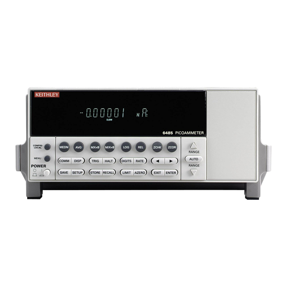
Page 31: Figure 1-1 Front Panel
When in Remote operation (REM annunciator lit), cancels GPIB remote mode. MENU Provides access to menu. POWER Power switch. In position turns 6485 on (I), out position turns it off (O). 2 Function keys MEDN Use to control and modify properties of the median filter. -
Page 32: Rear Panel Summary
Instrument addressed to talk over GPIB bus. TIMER Timer controlled triggering in use. TRIG External triggering (GPIB or trigger link) selected. 6 Handle Pull out and rotate to desired position. Rear panel summary The rear panel of Model 6485 is shown in Figure 1-2. -
Page 33: Figure 1-2 Rear Panel
1 INPUT This standard female BNC connector is used to connect the signal to be measured to the input of the Model 6485. Mates to a BNC cable. 2 CHASSIS This screw terminal is used to connect COMMON to CHASSIS ground via the ground link connector. -
Page 34: Analog Output
115V and 230VAC (nominal) at line frequencies of 50 or 60Hz automatically and over the bus. Changing line voltages requires changing fuses. Analog output The Model 6485 has an analog output on the rear panel. The ANALOG OUT provides a scaled, inverting ±2V output. A full-scale reading corresponds to ±2V output. WARNING The maximum safe voltage between picoammeter LO and chassis ground (common mode voltage) is 42V. -
Page 35: Figure 1-3 Typical Analog Output Connections
Model 6485 Picoammeter Instruction Manual Getting Started 1-11 Figure 1-3 Typical analog output connections CAT I MADE IN U.S.A. IEEE-488 ANALOG OUT (CHANGE IEEE ADDRESS WITH FRONT PANEL MENU) INPUT TRIGGER LINK RS-232 LINE RATING 220V PK 50, 60Hz 30 VA... -
Page 36: Display
Section Power-up Line power connection Follow the procedure below to connect the Model 6485 to line power and turn on the instrument. Check to see that the line voltage indicated in the window of the fuse holder assem- (Figure 1-2) is correct for the operating voltage in your area. -
Page 37: Line Frequency
Line frequency The Model 6485 operates at line frequencies of 50 or 60Hz. When auto detect is enabled (factory default), line frequencies are automatically sensed and set accordingly, therefore there are no switches to set. Use the :SYSTem:LFRequency? command (query) to read the line frequency. -
Page 38: Power-Up Sequence
Power-up sequence The following power-up sequence occurs when the Model 6485 is turned on: The Model 6485 performs self-tests on its EPROM and RAM with all digits and annunciators turned on. If a failure is detected, the instrument momentarily dis- plays an error message and the ERR annunciator turns on. -
Page 39: Default Settings
(FACT), three user-saved (USR0, USR1 and USR2), and bus default (GPIB). As shipped from the factory, Model 6485 powers up to the factory default settings. Factory default set- tings provide a general purpose setup for front panel operation, while the bus default (GPIB) settings do the same for remote operation. -
Page 40: Remote Setup Operation
Section Restoring factory or GPIB default setups The SYSTem:PRESet command returns Model 6485 to the factory defaults and the *RST command returns it to the GPIB defaults. The *RST command is documented in Section and SYSTem:PRESet is covered in... - Page 41 Model 6485 Picoammeter Instruction Manual Getting Started 1-17 Table 1-3 (continued) Default settings Factory GPIB Setting (:SYStem:PRESet) (*RST) GPIB: No effect (On at factory) Address No effect (14 at factory) Language No effect (SCPI at factory) Limit Tests: Limit 1 and Limit 2:...
-
Page 42: Menu
1-18 Getting Started Model 6485 Picoammeter Instruction Manual Menu Many aspects of operation are configured through the menus summarized in Table 1-4. Refer to the Section listed in the table in-depth information. To access the menu, press the MENU key. Use the range keys to scroll through the menu items, and the cursor keys to change options. -
Page 43: Optional Command Words
(?) that follows the command word. A query command requests (queries) the pro- grammed status of that command. When a query command is sent and Model 6485 is addressed to talk, the response message is sent to the computer. - Page 44 1-20 Getting Started Model 6485 Picoammeter Instruction Manual...
-
Page 45: Measurement Concepts
Measurement Concepts • Measurement overview — Explains the basic measurement capabilities of Model 6485. • Performance considerations — Covers a couple of considerations that affect overall performance; warm-up and autozero. • Connection fundamentals — Covers fundamental information about connecting test circuits to the picoammeter. -
Page 46: Measurement Overview
Performance considerations Warm-up period Model 6485 can be used within one minute after it is turned on. However, the instrument should be turned on and allowed to warm up for at least one hour before use to achieve rated accuracy. If the instrument has been exposed to extreme temperatures, allow extra time for the internal temperature to stabilize. -
Page 47: Scpi Programming
' Query autozero. 1=on, 0=off Connection fundamentals The following provides important fundamental information on input connections to the Model 6485. Typical connection drawings are included with the various measurement pro- cedures provided in subsequent sections of this manual. Input connector... -
Page 48: Maximum Input Levels
Figure 2-2. WARNING The maximum safe voltage between picoammeter LO and chassis ground (common mode voltage) is 42V. The Model 6485 does not inter- nally limit the LO-to-chassis voltage. Exceeding 42V can create a shock hazard. CAUTION The LO-to-chassis breakdown voltage is 500V. Exceeding this voltage may cause damage to the instrument. -
Page 49: Low Noise Input Cables
When making precision measurements, you should always use low noise cables. The fol- lowing low noise cables are recommended for use with Model 6485: Model 4801 Input Cable — This 4 ft (1.2m) low-noise triax cable is terminated with male BNC connectors on each end. -
Page 50: Basic Connections To Dut
Model 6485. To prevent this damage, the following steps should be taken as a protection precau- tion. (An alternate protection method is described in “Measuring high resistance with... - Page 51 The 14MΩ in series will increase the measured resistance to 100.014GΩ The 6485 can be programmed to calculate the resistance and subtract the series resistance. Using the M/X+B function, in the example above, one would set M to 500, B to -14e6, and the units character to “omega”.
-
Page 52: Figure 2-4 Shielding For Measurements (Unguarded)
WARNING The maximum safe voltage between picoammeter LO and chassis ground (common mode voltage) is 42V. The Model 6485 does not inter- nally limit the LO-to-chassis voltage. Exceeding 42V can create a shock hazard. -
Page 53: Input Voltage Overload (Ovrvolt Message)
(20µA to 20mA). Additionally, when operating on the 2mA and 20mA ranges or when the 6485 auto ranges up to these ranges as a response to the applied voltage, if the input voltage exceeds 60V, the Model 6485 will change from a current limit to a 1MΩ−... -
Page 54: Test Fixture Chassis
2-10 Measurement Concepts Model 6485 Picoammeter Instruction Manual Test fixture chassis • The chassis of the test fixture should be metal so that it can function as a shield for the DUT or test circuit. • The test box must have a lid that closes to prevent contact with live circuitry. -
Page 55: Input Protection
122° F (50° C) low-humidity environment for several hours. Input protection Model 6485 incorporates protection circuitry against nominal overload conditions. How- ever, a voltage higher than the maximum voltage value for the selected current range, and the resultant current surge could damage the input circuitry. -
Page 56: Floating Measurements
The maximum safe voltage between picoammeter LO and chassis ground (common mode voltage) is 42V. The Model 6485 does not inter- nally limit the LO-to-chassis voltage. Exceeding 42V can create a shock hazard. -
Page 57: Zero Check And Zero Correct
Model 6485 Picoammeter Instruction Manual Measurement Concepts 2-13 Figure 2-8 Floating measurements 6485 Picoammeter – Zero check and zero correct Table 2-3 lists the display messages associated with zero check and zero correct. The two-character message is displayed along with the reading. -
Page 58: Zero Correct
-Model 6485 will remain zero corrected even if it is upranged. If downranged, re-zero the instrument. -Model 6485 does not have to be re-zero corrected as long as the ambient tem- perature remains stable. -Zero correction cancels the voltage offset term of the amplifier. With both zero check and zero correct enabled, the instrument may not display a perfectly zeroed reading. -
Page 59: Scpi Programming - Zero Check And Zero Correct
Model 6485 Picoammeter Instruction Manual Measurement Concepts 2-15 SCPI programming — zero check and zero correct Table 2-4 SCPI commands — zero check and zero correct Commands Description Default SYSTem SYSTem Subsystem: :ZCHeck Zero check: [:STATe] <b> Enable or disable zero check. -
Page 60: B) System:zcorrect[:State]
Input bias current Offset current of Model 6485 could affect low current measurements. Voltage burden Offset voltage of Model 6485 could cause errors if it is high in relation to the voltage of the measured circuit. Noise Noise generated by source resistance and source capacitance. -
Page 61: Measurements
Measurements • Measurement overview — Summarizes the current measurement capabilities of Model 6485 and provides a basic procedure to measure amps. • SCPI programming — Covers the basic SCPI commands. -
Page 62: Measurement Overview
Measurements Model 6485 Picoammeter Instruction Manual Measurement overview Measurements — Model 6485 can make amps measurements from 20fA to 21mA using 8 measurement ranges; 2nA, 20nA, 200nA, 2µA, 20µA, 200µA, 2mA, and 20mA. NOTE Accuracy specifications are provided in Appendix... -
Page 63: Step 1. Enable Zero Check
NOTE When not making floating measurements, it is recommended that you ground measurement LO at only one place in the circuit, such as with the ground link connection on the rear panel of the 6485. (See “Ground loops,” page C-2.) -
Page 64: Figure 3-1 Connections For Amps
Measurements Model 6485 Picoammeter Instruction Manual Figure 3-1 Connections for amps Metal Noise Shield Metal Safety Input* Shield 4801, * 220V Peak 4802-10, or 4803 Safety Earth Ground CAT I MADE IN U.S.A. IEEE-488 ANALOG OUT (CHANGE IEEE ADDRESS WITH FRONT PANEL MENU) -
Page 65: Scpi Programming
To return a fresh (new) reading, you can send the INITiate command to trigger one or more readings before sending :DATA?. Details on INITiate are provided in Section While Model 6485 is busy performing measurements, the :DATA? command will not return the reading string until the instrument finishes and goes into the idle state. NOTE... - Page 66 Measurements Model 6485 Picoammeter Instruction Manual...
- Page 67 Range, Units, Digits, Rate, and Filters • Range, units, and digits — Provides details on measurement range, reading units, and display resolution selection. Includes the SCPI commands for remote opera- tion. • Rate — Provides details on reading rate selection. Includes the SCPI commands for remote operation.
-
Page 68: Range, Units, Digits, Rate, And Filters
Range, Units, Digits, Rate, and Filters Model 6485 Picoammeter Instruction Manual Range, units, and digits Range The ranges for current measurements are listed in Table 4-1. Table 4-1 Measurement ranges µA 2µA 20nA 20µA 20mA 200nA 200µA The full scale readings for every measurement range are 5% over range. For example, on the 20µA range, the maximum input current is ±... -
Page 69: Autorange Limits
2. Scientific notation provides more resolution on small values than engineering units. Digits The DIGITS key sets display resolution for Model 6485. Display resolution can be set from 3 to 6 digits. This single global setting affects display resolution for all measure- ment ranges. -
Page 70: Scpi Programming - Range And Digits
Note: Rational numbers can be used. For example, to set 5 resolution send a value of 4.5 (the 6485 rounds it to 5). Programming example — range and digits The following command sequence selects the 20mA range and sets display resolution to 3: *RST ' Restore RST defaults. -
Page 71: Rate
(NPLC), where 1 PLC for 60Hz is 16.67msec (1/60) and 1 PLC for 50Hz (and 400Hz) is 20msec (1/50). In general, Model 6485 has a parabola-like shape for its speed vs. noise characteristics and is shown in Figure 4-1. -
Page 72: Scpi Programming - Rate
Range, Units, Digits, Rate, and Filters Model 6485 Picoammeter Instruction Manual The rate setting is global for all ranges. Therefore, it does not matter what range is pres- ently selected when you set rate. There are two ways to set rate. You can select slow, medium, or fast by using the RATE key, or you can set the number of power cycles from the NPLC menu that is accessed by pressing CONFIG / LOCAL (while in LOCAL) and then RATE. -
Page 73: Programming Example - Rate
' Set integration rate to 2 PLC. Filters Filtering stabilizes noisy measurements caused by noisy input signals. The Model 6485 uses two types of filters: median and digital. The displayed, stored or transmitted reading is simply the result of the filtering processes. Note that both the median and digital filters can be in effect at the same time. -
Page 74: Median Filter Control
Digital filter Digital filter classifications Model 6485 has two classifications of the digital filter: averaging and advanced. Both are a simple average of one to 100 reading conversions. The difference between them is the user-programmable noise "window" for the advanced filter. -
Page 75: Figure 4-2 Digital Filter; Averaging And Advanced Classifications
Model 6485 Picoammeter Instruction Manual Range, Units, Digits, Rate, and Filters Figure 4-2 Digital filter; averaging and advanced classifications Current 1% of range Window Violation 1% of range 1% of range 1% of range Integrated Time Conversion: Class = averaging... -
Page 76: Response Time
4-10 Range, Units, Digits, Rate, and Filters Model 6485 Picoammeter Instruction Manual Figure 4-3 Digital filter types; moving and repeating Conversion Conversion Conversion Reading Reading Reading Conversion Conversion Conversion A. Class - Average, Readings = 10, Type - Moving Conversion... -
Page 77: Digital Filter Control
Model 6485 Picoammeter Instruction Manual Range, Units, Digits, Rate, and Filters 4-11 Digital filter control The AVG key is a toggle key: it will either enable the digital filter (displays AVERAGE ON) or disable the digital filter (displays AVERAGE OFF). To configure the median filter:... -
Page 78: Scpi Programming - Filters
4-12 Range, Units, Digits, Rate, and Filters Model 6485 Picoammeter Instruction Manual SCPI programming — filters Table 4-5 SCPI commands — filters Commands Description Default For median filter: [:SENSe[1]] SENSe Subsystem: :MEDian Median Filter: :RANK <n> Specify filter rank; 1 to 5. - Page 79 Relative, mX+b, m/X+b (reciprocal), and log • Relative — Explains how to null an offset or establish a baseline value. Includes the SCPI commands for remote operation. • mX+b, m/X+b (reciprocal), and Logarithmic — Covers these three basic math operations and includes the SCPI commands for remote operation.
-
Page 80: Relative, Mx+B, M/X+B (Reciprocal), And Log Relative
Rel’ed reading. However, this does not increase the maximum allowable input for that range. An over-range input signal will still cause the display to overflow. For example, on the 20µA range, Model 6485 still overflows for a 21µA input. NOTE Rel can be used on the result of the mX+b, m/X+b, or LOG calculations. -
Page 81: Displaying Or Manually Keying In Rel
Model 6485 Picoammeter Instruction Manual Relative, mX+b, m/X+b (reciprocal), and log Displaying or manually keying in REL Pressing CONFIG and then REL displays the present Rel value. This displayed Rel value can be enabled (pressing ENTER) or a different Rel value can be entered and enabled. -
Page 82: Scpi Programming - Relative
Relative, mX+b, m/X+b (reciprocal), and log Model 6485 Picoammeter Instruction Manual SCPI programming — relative Table 5-2 SCPI commands — relative (null) Commands Description Default CALCulate2 Path to configure and control limit testing (CALC2): :FEED <name> Specify reading to Rel; SENSe[1] or CALCulate[1]. -
Page 83: Programming Example - Relative
Model 6485 Picoammeter Instruction Manual Relative, mX+b, m/X+b (reciprocal), and log If the instrument is programmed to perform an infinite number of measurements (arm count or trigger count set to infinite), you cannot use the :DATA? command to return Rel’ed readings. However, you can use the :DATA:LATest? command to return the last Rel’ed reading after aborting the measurement process. -
Page 84: Logarithmic
This calculation converts input readings to logarithm base 10 values. The calculation is performed as follows: where: X is the input reading y is the logarithmic result For example: Assume that exactly 1mA is being measured by the Model 6485. 3 – 1.000000mA NOTE This calculation uses the absolute value of the normal input reading as the log of a negative number cannot be computed. -
Page 85: Scpi Programming - Mx+B, M/X+B, And Log
Model 6485 Picoammeter Instruction Manual Relative, mX+b, m/X+b (reciprocal), and log SCPI programming — mX+b, m/X+b, and log Table 5-3 SCPI commands — mX+b, m/X+b, and log Commands Description Default Ref CALCulate[1] CALCulate1 Subsystem: :FORMat <name> Select calculation; MXB, RECiprocal, or LOG10. -
Page 86: Programming Example - Mx+B
Relative, mX+b, m/X+b (reciprocal), and log Model 6485 Picoammeter Instruction Manual Programming example — mX+b This command sequence performs a single mX+b calculation and displays the result on the computer CRT: *RST 'Restores RST defaults. CALC:FORM MXB 'Selects mX+b calculation. -
Page 87: Buffer
Buffer • Buffer operations — Explains how to store and recall readings including buffer statistics. • SCPI programming — Covers the SCPI commands used to control buffer opera- tions. -
Page 88: Buffer Operations
Model 6485 Picoammeter Instruction Manual Buffer operations Model 6485 has a buffer to store from one to 2500 readings. It also stores overflow read- ings. Each reading has a timestamp. The timestamp for each reading is referenced to the time the measure/store process is started. In addition, recalled data includes statistical information (maximum, minimum, peak-to-peak, average and standard deviation). -
Page 89: Recall
Model 6485 Picoammeter Instruction Manual Buffer Figure 6-1 Buffer locations BUFFER BUFFER BUFFER 6485 PICOAMMETER 6485 PICOAMMETER 6485 PICOAMMETER Reading Value Timestamp Timestamp Reading Value Timestamp Timestamp Reading Value Timestamp Timestamp Reading Value Timestamp Timestamp Reading Value Timestamp Timestamp Reading Value... -
Page 90: Buffer Timestamps
Buffer Model 6485 Picoammeter Instruction Manual Buffer timestamps Use the TSTAMP: menu item to change the timestamp format. To access the menu: Press MENU. Scroll to the TSTAMP: menu item using RANGE keys and . Press ENTER. Using RANGE keys and , select desired setting. -
Page 91: Scpi Programming
TRACe:DATA? (which is the command to read the buffer). The CALCulate3 commands are used to obtain statistics from the buffer data. NOTE The Model 6485 uses IEEE-754 floating point format for statistics calculations. Table 6-1 SCPI commands — buffer Commands... - Page 92 Buffer Model 6485 Picoammeter Instruction Manual A) TRACe:FREE? Two values, separated by commas, are returned. The first value indicates how many bytes of memory are available, and the second value indicates how many bytes are reserved to store readings. B) TRACe:FEED <name>...
- Page 93 Model 6485 Picoammeter Instruction Manual Buffer • STATus — Includes a status word for each reading. It provides status information on instrument operation. (See Table 14-3.) • At least one data element must be in the list. Listed elements must be separated by a comma (i.e.
-
Page 94: Programming Example
The following program fragment stores 20 readings into the buffer and then calculates the mean average on the buffer readings: ' Select data elements: *RST ' Return 6485 to RST defaults. FORM:ELEM READ,TIME ' Select reading and timestamp. ' Store and Recall Readings:... -
Page 95: Triggering
SCPI programming — Includes the commands used to configure the trigger model and the commands to control the measurement process. • External triggering — Explains external triggering which allows Model 6485 to trigger other instruments and be triggered by other instruments. -
Page 96: Trigger Models
Model 6485 Picoammeter Instruction Manual Trigger models The flowcharts in Figure 7-1 Figure 7-2 summarize triggering for Model 6485. They are called trigger models because they are modeled after the SCPI commands to control triggering (operation) Figure 7-1 Trigger model — front panel operation... -
Page 97: Figure 7-2 Trigger Model — Remote Operation
Trigger-In Detector TRIGger:SOURce TLINk Source TRIGger:DELay <n> TRIGger:OUTPut SENSe | NONE Trigger Delay TRIGger:DELay:AUTO <b> 0.0 sec MEASURE Action Note: The following commands place the Model 6485 into idle: ABORt, *RST, SYSTem:PRESet, *RCL <NRf>, = Output Trigger DCL, and SDC. -
Page 98: Idle And Initiate
Typically, operation remains in the arm and trigger layers of the trigger model. However, Model 6485 can be put into the idle state at any time by press- ing the HALT key. To take the instrument out of idle, press the TRIG key. Other front panel keys can be pressed instead, but they may change the setup. -
Page 99: Event Detectors And Control Sources
Manual (ARM:SOURce MANual) — Event detection for the arm layer is satis- • fied by pressing the TRIG key. Model 6485 must be in the local mode for it to respond to the TRIG key. Press LOCAL or send LOCAL 14 over the bus to place Model 6485 in local. -
Page 100: Trigger Delay
A programmable delay is available after event detection. It can be set manually (0 to 999.9998 seconds) or an auto delay can be used. With auto delay selected, the Model 6485 automatically sets delay according to range. The auto delay settings are listed in Table 7-1. -
Page 101: Output Triggers
Triggering Output triggers Model 6485 can send out an output trigger (via the rear panel TRIGGER LINK connector) right after the measure action and/or when operation leaves the trigger layer. An output trigger can be used to trigger another instrument to perform an operation (e.g., select the next output step for a source). - Page 102 Triggering Model 6485 Picoammeter Instruction Manual Table 7-2 (continued) Trigger model menu structure Menu Description - - DELAY Set Trigger delay - - - MAN Specify trigger delay 0–999.9998sec. - - - AUTO Enable auto delay - - TRIG-OUT Configure output triggers...
-
Page 103: Scpi Programming
Model 6485 Picoammeter Instruction Manual Triggering SCPI programming Table 7-3 SCPI commands — triggering Command Description Default Ref ABORt Reset trigger system (goes to idle state). INITiate Initiate one trigger cycle. FETCh? Request latest reading. READ? Trigger and request a “fresh” reading. - Page 104 7-10 Triggering Model 6485 Picoammeter Instruction Manual A) ABORt If operation has been started by the INITiate command, ABORt will cancel all operations and immediately return to the instrument to the idle state. If operation has been started by READ? (or MEASure?), ABORt has no affect.
-
Page 105: Programming Example
Model 6485 Picoammeter Instruction Manual Triggering 7-11 Programming example The following command sequence will trigger and return 10 readings. *RST ' Return 6485 to RST defaults. ARM:SOURce IMMediate ' Set arm control source Immediate. ARM:COUNt 1 ' Set arm count to 1. TRIGger:SOURce IMMediate ' Set trigger control source Immediate. -
Page 106: Input Trigger Requirements
Minimum Output trigger specifications Model 6485 can be programmed to output a trigger immediately after a measurement and/ or when operation leaves the trigger layer of the trigger model. The output trigger provides a TTL-compatible output pulse that can be used to trigger other instruments. The specifi-... -
Page 107: External Trigger Example
DUT connected to that channel. Such a test system is shown in Figure 7-7, which uses a Model 6485 to measure 10 DUTs switched by a Model 7158 low current card in a Model 7001 or 7002 switch system. Figure 7-7... -
Page 108: Figure 7-8 Trigger Link Connections
Trigger Output Event = ON Trigger Count = 10 Trigger Delay = Auto To store readings in Model 6485 buffer, first set the number of points to store in the buffer: Press CONFIG and then STORE. Set the buffer size to 10 using the... -
Page 109: Figure 7-9 Operation Model For Triggering Example
The switching mainframes output pulse triggers Model 6485 to take a reading and store it. Model 6485 then sends an output trigger pulse to the switching mainframe to close the next channel. This process continues until all 10 channels are scanned, measured, and stored. - Page 110 Figure 7-9. Operation of Model 6485 starts at point A in the flowchart where it waits for an external trigger. Pressing STEP takes Model 7001/2 out of idle and places operation at point B in the flowchart.
-
Page 111: Limit Tests
Limit Tests • Limit testing — Explains the basic Limit 1 and Limit 2 testing operations. • Front panel operation — Explains how to configure and run tests from the front panel. • SCPI programming — Covers the SCPI commands for remote operation. -
Page 112: Limit Testing
Limit Tests Model 6485 Picoammeter Instruction Manual Limit testing As shown in Figure 8-1, there are two limit tests that can be performed on a DUT. Limit 1 is used as the wide pass band and Limit 2 is used as the narrow pass band. It is up to the user to specify limits that conform to this pass band relationship. - Page 113 Model 6485 Picoammeter Instruction Manual Limit Tests The 2-stage limit testing process is shown in Figure 8-3. If limit 1 fails, the L1 message is displayed and the test is finished. Limit 2 is not tested because the pass band relationship between the two stages implies that if limit 1 fails, limit 2 must also fail.
-
Page 114: Figure 8-3 Operation Model For Limit Test
Limit Tests Model 6485 Picoammeter Instruction Manual Figure 8-3 Operation model for limit test Start Measure Limit 1 Test Pass Display “L1” Limit 2 Test Pass Display “L2” Display “OK” NOTE Display messages indicate which test or tests have failed, but they do not indi- cate which limit (HI or LO) has failed. -
Page 115: Front Panel Operation
Model 6485 Picoammeter Instruction Manual Limit Tests Application — A typical application for a 2-stage limit test is to sort a batch of DUT according to tolerance. For example, you may want to sort diodes (all having the same nominal value) into three groups, 1%, 5%, and >5%. The limits for limit 1 would be the 5% tolerances, and the limits for limit 2 would be the 1% tolerances. -
Page 116: Perform Limit Tests
As previously explained, testing the system could be as simple as connecting a DUT to Model 6485. Step 2. Configure measurement Configure Model 6485 for the desired measurement as covered in the previous sections of this manual. Step 3. Configure limit tests Configure Model 6485 for the limit tests as explained in... -
Page 117: Scpi Programming
Model 6485 Picoammeter Instruction Manual Limit Tests SCPI programming Table 8-2 SCPI commands — limit tests Command Description Default :CALCulate2 CALCulate2 Subsystem: :FEED <name> Select input path for limit testing; CALCulate[1] SENS or SENSe[1]. :LIMit[1] Limit 1 Testing: :UPPer Configure upper limit: [:DATA] <n>... -
Page 118: Programming Example
Limit Tests Model 6485 Picoammeter Instruction Manual B) FAIL? In the event of a failure, you can read the measurement event register to determine which limit (upper or lower) failed. See Section 11 to program and read the measurement event register. -
Page 119: Remote Operation
Remote Operation • Selecting and configuring an interface — Explains how to select and configure an interface; GPIB or RS-232. • GPIB operation and reference — Covers the following GPIB topics: GPIB Bus Standards GPIB Bus Connections Primary Address Selection General Bus Commands Front Panel GPIB Operation Programming Syntax... -
Page 120: Selecting And Configuring An Interface
GPIB interface — The GPIB is the IEEE-488 interface. Model 6485 must be assigned to a unique address. At the factory the address is set to 14, but can be set to any value from 0 to 30. -
Page 121: Interface Selection And Configuration Procedures
Model 6485 Picoammeter Instruction Manual Remote Operation Interface selection and configuration procedures NOTE The unit will reset if the language is changed (SCPI, 488.1, and DDC). When you select (enable) the GPIB interface, the RS-232 interface disables. Conversely, selecting (enabling) the RS-232 interface disables the GPIB interface. -
Page 122: Gpib Operation And Reference
IEEE-488.2-1992 and defines a standard set of commands to control every programmable aspect of an instrument. GPIB bus connections To connect Model 6485 to the GPIB bus, use a cable equipped with standard IEEE-488 connectors as shown in Figure 9-1. -
Page 123: Figure 9-1 Ieee-488 Connector
Earlier versions had dif- ferent screws, which were silver-colored. Do not use these types of connectors on Model 6485 because it is designed for metric threads. Figure 9-2 shows a typical connecting scheme for a multiunit test system. -
Page 124: Figure 9-3 Ieee-488 Connector Location
IEEE-488 cables. Available shielded cables from Keithley are Models 7007-1 and 7007-2. To connect Model 6485 to the IEEE-488 bus, follow these steps: Line up the cable connector with the connector located on the rear panel. The con- nector is designed so that it will fit only one way. -
Page 125: Primary Address
Serial polls Model 6485. REN (remote enable) The remote enable command is sent to Model 6485 by the controller to set up the instru- ment for remote operation. Generally, the instrument should be placed in the remote mode before you attempt to program it over the bus. Simply setting REN true does not actually place the instrument in the remote state. -
Page 126: Ifc (Interface Clear)
DCL command is not an addressed command, so all instruments equipped to implement DCL will do so simultaneously. When Model 6485 receives a DCL command, it clears the input buffer and output queue, cancels deferred commands, and clears any command that prevents the processing of any other device command. -
Page 127: Get (Group Execute Trigger)
Remote Operation GET (group execute trigger) GET is a GPIB trigger that is used as an event to control operation. Model 6485 reacts to this trigger if it is the programmed control source. The control source is programmed from the SCPI TRIGger subsystem. -
Page 128: Local Key
9-10 Remote Operation Model 6485 Picoammeter Instruction Manual • SRQ — You can program the instrument to generate a service request (SRQ) when one or more errors or conditions occur. When this indicator is on, a service request has been generated. - Page 129 Model 6485 Picoammeter Instruction Manual Remote Operation 9-11 • Parameter types — The following are some of the common parameter types: <b> Boolean — Used to enable or disable an instrument operation. 0 or OFF disables the operation, and 1 or ON enables the operation.
-
Page 130: Query Commands
9-12 Remote Operation Model 6485 Picoammeter Instruction Manual Query commands The query command requests the presently programmed status. It is identified by the ques- tion mark (?) at the end of the fundamental form of the command. Most commands have a query form. -
Page 131: Program Messages
Model 6485 Picoammeter Instruction Manual Remote Operation 9-13 These rules apply to command words that exceed four letters: • If the fourth letter of the command word is a vowel, delete it and all letters after it. immediate = :imm •... -
Page 132: Multiple Command Messages
9-14 Remote Operation Model 6485 Picoammeter Instruction Manual Multiple command messages You can send multiple command messages in the same program message as long as they are separated by semicolons (;). The following is an example showing two commands in one program message: :stat:oper;... -
Page 133: Program Message Terminator (Pmt)
Command Messages”), the multiple response messages for all the queries is sent to the computer when Model 6485 is addressed to talk. The responses are sent in the order that the query commands were sent and are separated by semicolons (;). Items within the same query are separated by commas (,). -
Page 134: Response Message Terminator (Rmt)
9-2. Make sure the controller you connect to Model 6485 also uses these settings. NOTE You can break data transmissions by sending a ^C or ^X character string to Model 6485. This clears any pending operation and discards any pending out- put. -
Page 135: Baud Rate
2400, 1200, 600 or 300. Make sure that the programming terminal that you are connecting to Model 6485 can sup- port the baud rate you selected. Both Model 6485 and the other device must be configured for the same baud rate. -
Page 136: Rs-232 Connections
9-18 Remote Operation Model 6485 Picoammeter Instruction Manual RS-232 connections The RS-232 serial port can be connected to the serial port of a controller (i.e., personal computer) using a straight through RS-232 cable terminated with DB-9 connectors. Do not use a null modem cable. The serial port uses the transmit (TXD), receive (RXD), and signal ground (GND) lines of the RS-232 standard. -
Page 137: Error Messages
Model 6485 Picoammeter Instruction Manual Remote Operation 9-19 Table 9-2 RS-232 connector pinout Pin number Description DCD, data carrier detect TXD, transmit data RXD, receive data DTR, data terminal ready GND, signal ground DSR, data set ready RTS, ready to send... - Page 138 9-20 Remote Operation Model 6485 Picoammeter Instruction Manual...
-
Page 139: Status Structure
Status Structure • Overview — Provides an operational overview of the status structure for Model 6485. • Clearing registers and queues — Covers the actions that clear (reset) registers and queues. • Programming and reading registers — Explains how to program enable registers and read any register in the status structure. -
Page 140: Overview
Status Structure Model 6485 Picoammeter Instruction Manual Overview Model 6485 provides a series of status registers and queues allowing the operator to mon- itor and manipulate the various instrument events. The status structure is shown in Figure 10-1. The heart of the status structure is the status byte register. This register can be read by the users test program to determine if a service request (SRQ) has occurred and what event caused it. -
Page 141: Figure 10-1 6485 Status Mode Structure
Model 6485 Picoammeter Instruction Manual Status Structure 10-3 Figure 10-1 6485 status mode structure Event Enable Condition Event Register Register Register & & & & & & & Logical Calibration Summary & & & & & Error Queue & &... -
Page 142: Clearing Registers And Queues
Model 6485 Picoammeter Instruction Manual Clearing registers and queues When Model 6485 is turned on, the bits of all registers in the status structure are clear (reset to 0) and the two queues are empty. Commands to reset the event and event enable... -
Page 143: Programming And Reading Registers
Model 6485 Picoammeter Instruction Manual Status Structure 10-5 Programming and reading registers Programming enable registers The only registers that can be programmed by the user are the enable registers. All other registers in the status structure are read-only registers. The following explains how to ascertain the parameter values for the various commands used to program enable registers. -
Page 144: Figure 10-2 16-Bit Status Register
10-6 Status Structure Model 6485 Picoammeter Instruction Manual Figure 10-2 16-bit status register Bit Position Binary Value Decimal Weights (2 ) (2 ) (2 ) (2 ) (2 ) (2 ) (2 ) (2 ) A. Bits 0 through 7... -
Page 145: Status Byte And Service Request (Srq)
Model 6485 Picoammeter Instruction Manual Status Structure 10-7 Table 10-2 SCPI command — data formats for reading status registers Command Description Default :FORMat FORMat subsystem :SREGister <name> Select data format for reading status registers: ASCii <name>=ASCii Decimal format HEXadecimal Hexadecimal format... -
Page 146: Status Byte Register
(RQS) bit or the master summary status (MSS) bit: • When using the serial poll sequence of Model 6485 to obtain the status byte (a.k.a. serial poll byte), B6 is the RQS bit. See “Serial polling and SRQ,” page 10-9 details on using the serial poll sequence. -
Page 147: Serial Polling And Srq
Typically, SRQs are managed by the serial poll sequence of Model 6485. If an SRQ does not occur, bit B6 (RQS) of the status byte register will remain cleared, and the program will simply proceed normally after the serial poll is performed. -
Page 148: Programming Example - Set Mss (B6) When Error Occurs
Status register sets As shown in Figure 10-1, there are four status register sets in the status structure of Model 6485; standard event status, operation event status, measurement event status, and ques- tionable event status. Register bit descriptions Standard event status... -
Page 149: Figure 10-4 Standard Event Status
Bit B3, device-dependent error (DDE) — Set bit indicates that an instrument operation did not execute properly due to some internal condition. • Bit B4, execution error (EXE) — Set bit indicates that Model 6485 detected an error while trying to execute a command. •... -
Page 150: Operation Event Status
Bit B6, user request (URQ) — Set bit indicates that the LOCAL key on Model 6485 front panel was pressed. • Bit B7, power ON (PON) — Set bit indicates that Model 6485 has been turned off and turned back on since the last time this register has been read. Operation event status... -
Page 151: Measurement Event Status
Bit B7, reading overflow (ROF) — Set bit indicates that the reading exceeds the • selected measurement range of Model 6485. Bit B8, buffer available (BAV) — Set bit indicates that there are at least two read- • ings in the buffer. -
Page 152: Figure 10-6 Measurement Event Status
10-14 Status Structure Model 6485 Picoammeter Instruction Manual Figure 10-6 Measurement event status HL2F LL2F HL1F LL1F Measurement :CONDition? (B15 - B11) Condition Register (B2) (B1) (B10) (B9) (B8) (B7) (B6) (B5) (B4) (B3) (B0) HL2F LL2F HL1F LL1F Measurement... -
Page 153: Questionable Event Status
For example, while Model 6485 is in the idle state, bit B10 (Idle) of the operation condition register will be set. When the instrument is taken out of idle, bit B10 clears. -
Page 154: Event Registers
10-16 Status Structure Model 6485 Picoammeter Instruction Manual The commands to read the condition registers are listed in Table 10-4. For details on read- ing registers, see “Reading registers,” page 10-6. Table 10-4 Common and SCPI commands — condition registers... -
Page 155: Event Enable Registers
Model 6485 Picoammeter Instruction Manual Status Structure 10-17 Event enable registers Figure 10-1 shows, each status register set has an enable register. Each event register bit is logically ANDed (&) to a corresponding enable bit of an enable register. Therefore,... -
Page 156: Programming Example - Program And Read Registers
An empty output queue clears the MAV bit in the status byte register. A message is read from the output queue by addressing Model 6485 to talk after the appropriate query is sent. - Page 157 When empty, the message “0, No Error” is placed in the queue. Messages in the error queue are preceded by a code number. Negative (-) numbers are used for SCPI defined messages, and positive (+) numbers are used for Keithley defined messages. The messages are listed in Appendix B.
-
Page 158: Programming Example - Read Error Queue
10-20 Status Structure Model 6485 Picoammeter Instruction Manual Table 10-7 SCPI commands — error queue Command Description Default STATus STATus subsystem: :QUEue Read error queue: (Note 1) [:NEXT]? Read and clear oldest error/status (code and message). :ENABle <list> Specify error and status messages for error queue. -
Page 159: Common Commands
Common Commands... - Page 160 *OPT? Option query Returns model number of any installed options. *RCL <NRf> Recall command Returns Model 6485 to the user-saved setup. *RST Reset command Returns Model 6485 to the *RST default conditions. *SAV <NRf>...
- Page 161 The identification code includes the manufacturer, model number, serial number, and firm- ware revision levels and is sent in the following format: KEITHLEY INSTRUMENTS INC., MODEL 6485, xxxxxxx, yyyyy/zzzzz/w Where: xxxxxxx is the serial number. yyyyy/zzzzz is the firmware revision levels of the digital board ROM and display board ROM.
- Page 162 E) TRG — trigger Send bus trigger to Model 6485 Use the *TRG command to issue a GPIB trigger to Model 6485. It has the same effect as a group execute trigger (GET). Use the *TRG command as an event to control operation. Model 6485 reacts to this trigger if BUS is the programmed arm control source.
- Page 163 Use this query command to perform a checksum test on ROM. The command places the coded result (0 or 1) in the output queue. When Model 6485 is addressed to talk, the coded result is sent from the output queue to the computer.
- Page 164 11-6 Common Commands Model 6485 Picoammeter Instruction Manual...
-
Page 165: Scpi Signal Oriented Measurement Commands
SCPI Signal Oriented Measurement Commands... - Page 166 If the instrument is in idle, this command will execute immediately. If the instrument is not in idle, execution of the command will execute when the operation returns to the idle state. When this command is executed, Model 6485 will be configured as follows: •...
- Page 167 Request latest reading This command requests the latest post-processed readings. After sending this command and addressing Model 6485 to talk, the readings are sent to the computer. This command does not affect the instrument setup. This command does not trigger a measurement. The command simply requests the last group of readings.
- Page 168 12-4 SCPI Signal Oriented Measurement Commands Model 6485 Picoammeter Instruction Manual D) MEASure[:<function>]? Configure and perform “one-shot” measurement <function> = CURRent[:DC] Measure current This command combines all of the other signal oriented measurement commands to per- form a “one-shot” measurement and acquire the reading.
-
Page 169: Display, Format, And System
DISPlay, FORMat, and SYSTem • DISPlay subsystem — Covers the SCPI commands that are used to control the display. • FORMat subsystem — Covers the SCPI commands to configure the format that readings are sent over the bus. • SYSTem subsystem —... -
Page 170: Display Subsystem
13-2 DISPlay, FORMat, and SYSTem Model 6485 Picoammeter Instruction Manual DISPlay subsystem The commands in this subsystem are used to control the display over the bus. Table 13-1 SCPI commands — display Command Description Default :DISPlay :DIGits <n> Set display resolution; 4 to 7. -
Page 171: Format Subsystem
Model 6485 Picoammeter Instruction Manual DISPlay, FORMat, and SYSTem 13-3 message (on the same line), it will be treated as part of the message and is displayed instead of executed. C) DISPlay:TEXT:STATe <b> When the text message mode is enabled, a defined message is displayed. When disabled, the message is removed from the display. -
Page 172: Figure 13-1 Ascii Data Format
13-4 DISPlay, FORMat, and SYSTem Model 6485 Picoammeter Instruction Manual A) FORMat[:DATA] <type>[,<length>] Parameters ASCii = ASCII format REAL, 32 = Binary IEEE-754 single precision format SREal = Binary IEEE-754 single precision format NOTE <length> is not used for the ASCii or SREal parameters. It is optional for the REAL parameter. -
Page 173: Figure 13-2 Ieee-754 Single Precision Data Format (32 Data Bits)
The header and terminator are sent only once for each READ?. During binary transfers, never un-talk Model 6485 until after the data is read (input) to the computer. Also, to avoid erratic operation, the readings of the data string (and terminator) should be acquired in one piece. - Page 174 (delta format). The TRACe:TSTamp:FORMat command is used to select the timestamp format. Status — The status word provides information about Model 6485 operation. The 16-bit status word is sent in decimal form. The decimal value has to be converted to the binary equivalent to determine the state of each bit in the word.
- Page 175 Model 6485 Picoammeter Instruction Manual DISPlay, FORMat, and SYSTem 13-7 Bit 6 Bit 5 All limit tests passed CALC2:LIM1 test failed CALC2:LIM2 test failed Bit 7 (Overvoltage) — Set to 1 if measurement performed with an overvoltage condition on the input.
-
Page 176: System Subsystem
:KEY <NRf> Simulate key-press; see Figure 13-3. RS-232 interface: Section 9 :LOCal Take Model 6485 out of remote (RS-232 only). Equivalent to GTL. :REMote Put Model 6485 in remote (RS-232 only). Equivalent to REN. :RWLock Enable local lockout (RS-232 only). - Page 177 *SAV command. See Section 12 (Common Commands) for details. D) SYSTem:VERSion Read the version of the SCPI standard being used by Model 6485. Example response mes- sage: 1996.0. E) SYSTem:KEY <NRf> Parameters 1 = CONFIG/LOCAL key...
-
Page 178: Figure 13-3 Key-Press Codes
The queue for the :SYST:KEY? query command can only hold one key-press. When :SYST:KEY? is sent and Model 6485 is addressed to talk, the key-press code number for the last :SYST:KEY command is sent to the computer. The value is -1 if a :SYST:KEY command has not been sent since the last time the unit was placed in remote. -
Page 179: Scpi Reference Tables
SCPI Reference Tables • Table 14-1 — CALCulate command summary • Table 14-2 — DISPlay command summary • Table 14-3 — FORMat command summary • Table 14-4 — SENSe command summary • Table 14-5 — STATus command summary • Table 14-6 —... -
Page 180: General Notes
14-2 SCPI Reference Tables Model 6485 Picoammeter Instruction Manual General notes • Brackets ([ ]) are used to denote optional character sets. These optional characters do not have to be included in the program message. Do not use brackets in the program message. - Page 181 Model 6485 Picoammeter Instruction Manual SCPI Reference Tables 14-3 Table 14-1 (continued) CALCulate command summary Default Command Description parameter Section SCPI :CALCulate[1](continued) √ :DATA? Return all CALC1 results triggered by INITiate. :LATest? Return last (latest) reading. √ :CALCulate2 Path to configure and control limit testing (CALC2): √...
- Page 182 14-4 SCPI Reference Tables Model 6485 Picoammeter Instruction Manual Table 14-1 (continued) CALCulate command summary Default Command Description parameter Section SCPI √ :CALCulate3 Path to configure and control CALC3 calculations on buffer data: √ :FORMat <name> Select buffer statistic; MEAN, SDEViation, MEAN Maximum, MINimum or PKPK.
- Page 183 Model 6485 Picoammeter Instruction Manual SCPI Reference Tables 14-5 Table 14-3 FORMat command summary Default Command Description parameter Section SCPI :FORMat √ [:DATA] <type>[,<length>] Specify data format; ASCii, REAL, 32, or SREal. √ [:DATA]? Query data format. :ELEMents <item list>...
- Page 184 14-6 SCPI Reference Tables Model 6485 Picoammeter Instruction Manual Table 14-4 (continued) SENSe command summary Default Ref. Command Description parameter Section SCPI √ :AUTO? Query state of autorange. :ULIMit <NRf> Select autorange upper limit; -0.021 to 2.1e-2 0.021 (amps). :ULIMit? Query upper limit for autorange.
- Page 185 Model 6485 Picoammeter Instruction Manual SCPI Reference Tables 14-7 Table 14-5 (continued) STATus command summary Default Command Description parameter Section SCPI :ENABle? Read the enable register. :CONDition? Read the condition register. √ :OPERation Operation event registers: √ [:EVENt]? Read the event register.
- Page 186 14-8 SCPI Reference Tables Model 6485 Picoammeter Instruction Manual Table 14-6 SYSTem command summary (see Section 13 for detailed information) Default Command Description parameter Section SCPI :SYSTem :ZCHeck Zero check: [:STATe] <b> Enable or disable zero check. [:STATe]? Query state of zero check.
- Page 187 RS-232 interface: :LOCal While in LLO, removes the LLO and places the Model 6485 in local (RS-232 only). :REMote Places the Model 6485 in remote if not in LLO (RS-232 only). :RWLock Places the Model 6485 in local lockout (RS-232 only).
- Page 188 14-10 SCPI Reference Tables Model 6485 Picoammeter Instruction Manual Table 14-8 TRIGger command summary Default Command Description parameter Section SCPI √ :INITiate Path to initiate measurement cycle(s): √ [:IMMediate] Initiate one trigger cycle. √ :ABORt Reset trigger system (goes to idle state).
- Page 189 Model 6485 Picoammeter Instruction Manual SCPI Reference Tables 14-11 Table 14-8 (continued) TRIGger command summary Default Command Description parameter Section SCPI √ :DIRection <name> Enable (SOURce) or disable (ACCeptor) ACCeptor bypass. √ :DIRection? Query trigger source bypass. [:ASYNchronous] Configure input/output triggers: :ILINe <NRf>...
- Page 190 14-12 SCPI Reference Tables Model 6485 Picoammeter Instruction Manual...
-
Page 191: Performance Verification
Performance Verification • Verification test requirements — Summarizes environmental conditions, warm- up period, and line power requirements. • Recommended test equipment — Lists all equipment necessary for verification and gives pertinent specifications. • Verification limits — Describes how reading limits are calculated and gives an example. -
Page 192: Introduction
15-2 Performance Verification Model 6485 Instruction Manual Introduction Use the procedures in this section to verify that Model 6485 accuracy is within the limits stated in the instrument’s one-year accuracy specifications. You can perform these verifica- tion procedures: • When you first receive the instrument to make sure that it was not damaged during shipment. -
Page 193: Warm-Up Period
Allow the test equipment to warm up for the minimum time specified by the manufacturer. Line power The Model 6485 requires a line voltage of 100/120V or 220/240V at a line frequency of 50 to 60Hz. Verification tests must be performed within this range. Be sure the line voltage... - Page 194 15-4 Performance Verification Model 6485 Instruction Manual Table 15-1 Recommended performance verification equipment Description Manufacturer/Model Specifications Calibrator Fluke 5700A DC Voltage: 2V: 7ppm 20V: 5ppm 200V: 7ppm DC Current: 20µA: 550ppm 200µA: 100ppm 2mA: 55ppm 20mA: 55ppm Electrometer Calibration Keithley Model 5156...
-
Page 195: Verification Limits
15-5 Verification limits The verification limits stated in this section have been calculated using only Model 6485 one-year accuracy specifications, and they do not include test equipment uncertainty. If a particular measurement falls outside the allowable range, recalculate new limits based on both Model 6485 specifications and corresponding test equipment specifications. -
Page 196: Performing The Verification Test Procedures
Test considerations When performing the verification procedures: • Be sure to restore Model 6485 factory front panel defaults, and perform voltage offset calibration as outlined below. • Make sure that the test equipment is properly warmed up and properly connected to the Model 6485 INPUT jack. -
Page 197: Offset Voltage Calibration
15-1. Use the appropriate low-noise coaxial cable, and BNC-to-dual banana plug adapter where shown. Set the Model 6485 to the 20µA range using the up or down RANGE key. With zero check enabled, zero correct the Model 6485, then disable zero check. -
Page 198: 2Na-2Ma Range Accuracy
With zero check enabled, zero correct the instrument then disable zero check. Set the calibrator voltage to 0.0000V and make sure the output is turned on. Enable the Model 6485 REL mode. Leave REL enabled for the remainder of the test. - Page 199 • Set the calibrator to the calculated voltage. • Verify that the Model 6485 current reading is within the reading limits listed in the table. Repeat the procedure for negative source currents with the same magnitudes as those listed in Table 15-3.
-
Page 200: Figure 15-2 Connections For 2Na To 2Μa Range Verification
15-10 Performance Verification Model 6485 Instruction Manual Figure 15-2 Connections for 2nA to 2 µ A range verification DC Voltage Calibrator BNC-to-dual Banana Plug Model 6485 Picoammeter Adapter MADE IN U.S.A. IEEE-488 (CHANGE IEEE ADDRESS ANALOG OUT WITH FRONT PANEL MENU) -
Page 201: Calibration
— Lists considerations to take into account when cali- brating the unit. • Calibration cycle — States how often the Model 6485 should be calibrated. • Recommended calibration equipment — Lists all equipment necessary for cali- bration and gives pertinent specifications. -
Page 202: Introduction
Allow the test equipment to warm up for the minimum time specified by the manufacturer. Line power The Model 6485 requires a line voltage of 100/120V or 220/240V at a line frequency of 50 to 60Hz. The instrument must be calibrated while operating from a line voltage within this range. -
Page 203: Calibration Considerations
• Always allow the source signal to settle before calibrating each point. • Do not connect test equipment to the Model 6485 through a scanner or other switching equipment. • If an error occurs during calibration the Model 6485 will generate an appropriate error message. -
Page 204: Calibration Errors
23˚±3˚C accuracy of characterization. Calibration errors The Model 6485 checks for errors after each calibration step, minimizing the possibility that improper calibration may occur due to operator error. If an error is detected during calibration, the instrument will display an appropriate error message. The unit will then... -
Page 205: Calibration Menu
Model 6485 Instruction Manual Calibration 16-5 Table 16-2 Test uncertainty ratios with recommended equipment Test uncertainty Range 5700 + 5156 ratio 7ppm + 300ppm 13.0 20nA 7ppm + 200ppm 19.3 200nA 5ppm + 200ppm 7ppm + 200ppm 20uA 550ppm 200uA 100ppm 10.0... -
Page 206: Aborting Calibration
Locking out calibration Preparing for calibration Turn on the Model 6485 and the calibrator, and allow them to warm up for at least one hour before performing calibration. Press MENU, select CAL, then press ENTER. The instrument will display the fol-... -
Page 207: Offset Voltage Calibration
Press EXIT to return to normal display. Current calibration 20µA-20mA range calibration Connect the BNC shielding cap to the Model 6485 rear panel INPUT jack. Select the Model 6485 20µA range. Press MENU, select CAL, then press ENTER. At the CAL: RUN prompt, press ENTER. - Page 208 Model 6485 Instruction Manual Press ENTER. The unit will prompt for the negative full-scale calibration point: -20µA CAL Press ENTER. The Model 6485 will prompt for the negative full-scale calibration current: -20.00000 µA Set the calibrator output to –20.00000µA, then adjust the display to agree with the calibrator value.
-
Page 209: 2Na-2Ma Range Calibration
Set the calibrator voltage to +2.000000V. Calculate the actual calibration current from the calibrator voltage and the actual standard resistor value: I = V/R. Adjust the Model 6485 display to agree with the calculated current, then press ENTER. The Model 6485 will prompt for the negative full-scale calibration point: -2NA CAL Press ENTER. - Page 210 Set the calibrator output voltage to –2.000000V, then calculate the calibration cur- rent from the calibrator voltage and standard resistor value: I = V/R. Adjust the Model 6485 display to agree with the calculated current, then press ENTER to complete calibration of the present range.
-
Page 211: Entering Calibration Dates And Saving Calibration
Model 6485 Instruction Manual Calibration 16-11 Figure 16-2 Connections for 2nA to 2 µ A range calibration DC Voltage Calibrator BNC-to-dual Banana Plug Model 6485 Picoammeter Adapter MADE IN U.S.A. IEEE-488 (CHANGE IEEE ADDRESS ANALOG OUT WITH FRONT PANEL MENU) -
Page 212: Locking Out Calibration
16-12 Calibration Model 6485 Instruction Manual Locking out calibration Use the following procedure to lock out calibration without saving new calibration con- stants: Press MENU, select CAL, then press ENTER. Use the up RANGE key to display the following: CAL: LOCK Press ENTER. -
Page 213: Displaying Calibration Dates
CAL: VOFFSET Use either RANGE key to select CAL: DATES, then press ENTER. The Model 6485 will display the last calibration date, for example: DATE: 11/15/01 Press ENTER to view the calibration due date, for example: NDUE: 11/15/02 Press EXIT to return to normal display. - Page 214 16-14 Calibration Model 6485 Instruction Manual...
-
Page 215: Routine Maintenance
Routine Maintenance • Setting line voltage and replacing line fuse — Describes how to set the line volt- age properly and replace the line fuse with the correct rating. • Front panel tests — Covers testing the front panel keys and the display. -
Page 216: Introduction
17-2 Routine Maintenance Model 6485 Instruction Manual Introduction The information in this section deals with routine type maintenance that can be performed by the operator and includes procedures for setting the line voltage, replacing the line fuse, and running the front panel tests. -
Page 217: Front Panel Tests
Model 6485 Instruction Manual Routine Maintenance 17-3 Figure 17-1 Line fuse location Model 6485 Picoammeter MADE IN U.S.A. IEEE-488 (CHANGE IEEE ADDRESS ANALOG OUT WITH FRONT PANEL MENU) TRIGGER LINK RS-232 INPUT INPUT LINE RATING 220V PK 50, 60Hz 30 VA MAX... -
Page 218: Disp Test
17-4 Routine Maintenance Model 6485 Instruction Manual DISP test The display test allows you to verify that each segment and annunciator in the vacuum fluorescent display is working properly. Perform the following steps to run the display test: Press MENU, select TEST, and press ENTER to access the self-test options. -
Page 219: Specifications
Specifications... - Page 220 Shipping Weight: <5 kg (<11 lbs). Calibration (SCPI mode only), Display Format, SRQ, REL, Output Format, V-offset Cal. ADDRESS MODES: TALK ONLY and ADDRESSABLE. LANGUAGE EMULATION: Keithley Model 485 emulation via DDC mode. RS-232 IMPLEMENTATION: Supports: SCPI 1996.0. Baud Rates: 300, 600, 1200, 2400, 4800, 9600, 19.2k, 38.4k, 57.6k.
-
Page 221: Status And Error Messages
Status and Error Messages... - Page 222 Status and Error Messages Model 6485 Picoammeter Instruction Manual Table B-1 Status and error messages Number Description Event -440 Query unterminated after indefinite response -430 Query deadlocked -420 Query unterminated -410 Query interrupted -363 Input buffer overrun -362 Framing error in program message...
-
Page 223: Table B-1 Status And Error Messages
Model 6485 Picoammeter Instruction Manual Status and Error Messages Table B-1 (continued) Status and error messages Number Description Event -158 String data not allowed -154 String too long -151 Invalid string data -150 String data error -148 Character data not allowed... - Page 224 Status and Error Messages Model 6485 Picoammeter Instruction Manual Table B-1 (continued) Status and error messages Number Description Event +107 Reading overflow +108 Buffer available +109 Buffer full +110 Input overvoltage Standard events: +200 Operation complete Operation events: +300 Device calibrating...
- Page 225 Model 6485 Picoammeter Instruction Manual Status and Error Messages Table B-1 (continued) Status and error messages Number Description Event Additional (more informative) command execution errors: +800 Illegal with storage active +801 Insufficient vector data +804 Expression list full +805 Undefined expression exists...
- Page 226 Status and Error Messages Model 6485 Picoammeter Instruction Manual Table B-1 (continued) Status and error messages Number Description Event Keithley 6485 Serial Poll Byte Events: +962 DDC Ready +963 DDC Reading Done +965 DDC Buffer Full +966 DDC Reading overflow...
-
Page 227: General Measurement Considerations
General Measurement Considerations... -
Page 228: Measurement Considerations
The configu- ration that results in the lowest noise signal is the one that should be used. A convenient way to make this connection uses the ground link at the rear of the 6485. -
Page 229: Triboelectric Effects
Triboelectric currents can be minimized as follows: • Use “low noise” cables. These cables are specially designed to minimize charge generation and use graphite to reduce friction. The Keithley Model 4801–4803 cables are low noise. • Use the shortest cables possible, and secure them (i.e., taping or tying) to a non-vibrating surface to keep them from moving. -
Page 230: Electrochemical Effects
With this in mind, the Model 6485 display may be turned off either through the front panel by pressing the DISP, or over the bus by sending the :DISP:ENAB OFF command. -
Page 231: Magnetic Fields
Electromagnetic Interference (EMI) The electromagnetic interference characteristics of the Model 6485 comply with the elec- tromagnetic compatibility (EMC) requirements of the European Union as denoted by the CE mark. However, it is still possible for sensitive measurements to be affected by exter- nal sources. - Page 232 General Measurement Considerations Model 6485 Picoammeter Instruction Manual The effect on instrument performance can be considerable if enough of the unwanted sig- nal is present. The effects of EMI can be seen as an unusually large offset, or, in the case of impulse sources, erratic variations in the displayed reading.
-
Page 233: Ddc Emulation Commands
DDC Emulation Commands... -
Page 234: Ddc Language
D-1. For details on Model 485 operation, refer to the appropriate instruction manual. Since the architecture of the Model 6485 differs from that of the other picoammeters, some commands are different and cannot be used. Be sure to refer to the notes at the end of the table for information on command restrictions. - Page 235 Model 6485 Picoammeter Instruction Manual DDC Emulation Commands Table D-1 (continued) Device dependent command summary Description Mode Command Note Default Equivalent SCPI commands Reading with prefix (NDCA-1.23456E-02) SCPI not avail- Reading without prefix (-1.23456E-02) Data able—see Reading with prefix and buffer suffix (if in B1)
- Page 236 DDC Emulation Commands Model 6485 Picoammeter Instruction Manual Table D-1 (continued) Device dependent command summary Description Mode Command Note Default Equivalent SCPI commands Reading Done (B3) (cont.) STATus:MEASurement[:EVENt]:ENABle 64 *SRE <value> value = (current *SRE value) |= (0x01) Reading Done or Reading Overflow...
- Page 237 Model 6485 Picoammeter Instruction Manual DDC Emulation Commands Table D-1 (continued) Device dependent command summary Description Mode Command Note Default Equivalent SCPI commands Busy, Reading Done or Reading Overflow (B4, B3, (cont.) *ESE 1 STATus:MEASurement[:EVENt]:ENABle 192 *SRE <value> value = (current *SRE value) |= (0x20|0x01)
- Page 238 DDC Emulation Commands Model 6485 Picoammeter Instruction Manual Table D-1 (continued) Device dependent command summary Description Mode Command Note Default Equivalent SCPI commands Zero Correct disabled SYSTem:ZCORrect:STATe OFF Zero Zero Correct enabled Correct SYSTem:ZCORrect:ACQuire SYSTem:ZCORrect:STATe ON Filter off Digital Filter off Filter Repeat Filter on, where filter size “n”...
- Page 239 Model 6485 Picoammeter Instruction Manual DDC Emulation Commands Table D-1 (continued) Device dependent command summary Description Mode Command Note Default Equivalent SCPI commands [SENSe[1]][:CUR- Rent:[DC]]:RANGe[:UPPer]:2e-3 20mA Range [SENSe[1]][:CUR- (cont.) Rent:[DC]]:RANGe[:UPPer]:20e-3 Cancel Auto range [SENSe[1]]:CUR- Rent:[DC]:RANGe[:UPPer]:AUTO OFF Continuous, triggered by talk...
- Page 240 Y commands used by the 485. Also note that the “YY” response to the U0 command is different. D. For the Model 6485, the Buffer Full bit in the U1X status word does not get cleared until either the buffer is resized or buffer storage is reactivated. Note that requesting a buffer reading does not clear the U1 Buffer Full bit.
- Page 241 Model 6485 Picoammeter Instruction Manual DDC Emulation Commands H. Although there is not a ‘Busy’ event in the Model 6485 Status Model, there is an Operation Complete event (the compliment of ‘Busy’). This example refers to the use of the Operation Complete SRQ (rather than ‘Busy’).
-
Page 242: Figure D-1 U0 Status Word
D-10 DDC Emulation Commands Model 6485 Picoammeter Instruction Manual Figure D-1 U0 Status word STATUS WORD : CR LF = LF CR , LF . CR None 0 = Off 1 = On 00 = SRQ Disabled 01 = IDDCO... -
Page 243: Figure D-2 U1 Status Word
Model 6485 Picoammeter Instruction Manual DDC Emulation Commands D-11 Figure D-2 U1 Status word STATUS (DATA CONDITION) FORMAT 1 = Full 0 = Off 1 = On 0 = Picoammeter 1 = Buffer Reading 2 = Maximum Reading 3 = Minimum Reading... -
Page 244: Status Byte Format
When an SRQ is generated by the Model 6485, bit 6 of the status byte will be set. If the SRQ was caused by an error condition, bit 5 will also be set along with one of the error condition bits (B0, B1, or B2). - Page 245 Not in remote — Model 6485 in local mode of operation. NOTE Once the Model 6485 has generated an SRQ, its status byte must be read to clear the SRQ line. Otherwise, the instrument will continuously assert SRQ. The Model 6485 may be programmed to generate an SRQ for more than one condition simultaneously.
-
Page 246: Figure D-4 Status Byte Format
D-14 DDC Emulation Commands Model 6485 Picoammeter Instruction Manual Figure D-4 Status byte format Data Conditions B5 = 0 Data Reading Reading Busy Store Done Overflow Full 0=Data 1=SRQ 1=Error IDDC IDDCO Remote Error Conditions B5 = 1... -
Page 247: Example Programs
Example Programs... -
Page 248: Programming Examples
Figure G-2): 1000 readings/second into internal buffer NOTE This program configures the Model 6485 to 0.01 PLC, digital filters off, front panel off, auto-zero off, as well as takes and stores 2500 readings. *RST ' Return 6485 to RST defaults. -
Page 249: 900 Readings/Second To Ieee-488 Bus
NOTE This program configures the Model 6485 to 0.01 PLC, digital filters off, front panel off, auto-zero off, binary transfer, and IEEE-488.1 (language). Model 6485 must be set to IEEE-488.1 operation from the front panel, see page G-4. - Page 250 Example Programs Model 6485 Picoammeter Instruction Manual...
-
Page 251: Ieee-488 Bus Overview
IEEE-488 Bus Overview... -
Page 252: Introduction
IEEE-488 Bus Overview Model 6485 Picoammeter Instruction Manual Introduction The IEEE-488 bus is a communication system between two or more electronic devices. A device can be either an instrument or a computer. When a computer is used on the bus, it serves as a supervisor of the communication exchange between all the devices and is known as the controller. - Page 253 The IEEE-488 standards also include another addressing mode called secondary address- ing. Secondary addresses lie in the range of $60-$7F. Note, however, that many devices, including the Model 6485, do not use secondary addressing. Once a device is addressed to talk or listen, the appropriate bus transactions take place. For example, if the instrument is addressed to talk, it places its data string on the bus one byte at a time.
-
Page 254: Bus Lines
IEEE-488 Bus Overview Model 6485 Picoammeter Instruction Manual Figure F-1 IEEE-488 bus configuration TO OTHER DEVICES DEVICE 1 ABLE TO TALK, LISTEN AND CONTROL (COMPUTER) DATA BUS DEVICE 2 ABLE TO TALK AND LISTEN DATA BYTE 6485 2182 TRANSFER CONTROL... -
Page 255: Data Lines
Model 6485 Picoammeter Instruction Manual IEEE-488 Bus Overview Data lines The IEEE-488 bus uses eight data lines that transfer data one byte at a time. DIO1 (Data Input/Output) through DIO8 (Data Input/Output) are the eight data lines used to transmit both data and multiline commands and are bi-directional. -
Page 256: Bus Commands
IEEE-488 Bus Overview Model 6485 Picoammeter Instruction Manual transfer. If these conditions are not met, the source must wait until NDAC and NRFD have the correct status. If the source is a controller, NRFD and NDAC must be stable for at least 100ns after ATN is set true. - Page 257 Model 6485 Picoammeter Instruction Manual IEEE-488 Bus Overview These bus commands and their general purpose are summarized in Table F-1. Table F-1 IEEE-488 bus command summary State of Command type Command line Comments Uniline REN (Remote Enable) Set up devices for remote operation.
- Page 258 IEEE-488 Bus Overview Model 6485 Picoammeter Instruction Manual Table F-2 Command codes...
-
Page 259: Uniline Commands
Model 6485 Picoammeter Instruction Manual IEEE-488 Bus Overview Uniline commands ATN, IFC, and REN are asserted only by the controller. SRQ is asserted by an external device. EOI may be asserted either by the controller or other devices depending on the direction of data transfer. -
Page 260: Addressed Multiline Commands
ORing the address with $40. Talk commands are used to address devices to talk. SCG (Secondary Command Group) — Commands in this group provide additional addressing capabilities. Many devices (including the Model 6485) do not use these com- mands. -
Page 261: Common Commands
Model 6485 Picoammeter Instruction Manual IEEE-488 Bus Overview F-11 Common commands Common commands are commands that are common to all devices on the bus. These com- mands are designated and defined by the IEEE-488.2 standard. Generally, these commands are sent as one or more ASCII characters that tell the device to perform a common operation, such as reset. -
Page 262: Typical Command Sequences
F-12 IEEE-488 Bus Overview Model 6485 Picoammeter Instruction Manual Typical command sequences For the various multiline commands, a specific bus sequence must take place to properly send the command. In particular, the correct listen address must be sent to the instrument before it will respond to addressed commands. -
Page 263: Ieee Command Groups
Model 6485 Picoammeter Instruction Manual IEEE-488 Bus Overview F-13 IEEE command groups Command groups supported by the Model 6485 are listed in Table F-6. Common com- mands and SCPI commands are not included in this list. Table F-6 IEEE command groups... -
Page 264: Interface Function Codes
Open collector bus drivers No Extended Talker capability No Extended Listener capability The codes define Model 6485 capabilities as follows: SH (Source Handshake Function) — SH1 defines the ability of the instrument to initiate the transfer of message/data over the data bus. - Page 265 Model 6485 Picoammeter Instruction Manual IEEE-488 Bus Overview F-15 RL (Remote-Local Function) — RL1 defines the ability of the instrument to be placed in the remote or local modes. TE (Extended Talker Function) — The instrument does not have extended talker capa- bilities (TE0).
- Page 266 F-16 IEEE-488 Bus Overview Model 6485 Picoammeter Instruction Manual...
- Page 267 IEEE-488 and SCPI Conformance Information...
-
Page 268: Ieee-488 And Scpi Conformance Information
IEEE-488 and SCPI Conformance Information Model 6485 Picoammeter Instruction Manual Introduction The IEEE-488.2 standard requires specific information about how the Model 6485 imple- ments the standard. Paragraph 4.9 of the IEEE-488.2 standard (Std 488.2-1987) lists the documentation requirements. Table G-1 provides a summary of the requirements and pro- vides the information or references the manual for that information. -
Page 269: Gpib 488.1 Protocol
TRAC:FEED:CONT <name> TRAC:CLE GPIB 488.1 Protocol The Model 6485 supports two GPIB protocols: SCPI (488.2) and 488.1. The 488.1 proto- col is included to significantly increase speed over the GPIB. When using the 488.1 protocol, throughput is enhanced up to 10 times for data sent to the 6485 (command messages) and up to 20 times for data returned by the Picoammeter (response messages). -
Page 270: Selecting The 488.1 Protocol
Perform the following steps to select the 488.1 protocol: NOTE The 6485 must be set up to be remotely controlled over the GPIB to select the 488.1 protocol. SCPI language is the only language available over the RS-232 bus. To setup to use GPIB from the local measurement mode:... -
Page 271: Message Exchange Protocol (Mep
• When sending a command or query, do not attempt to read data from the 6485 until the terminator has been sent (usually Line Feed with EOI). Otherwise, a DCL or IFC must be sent to reset the input parser. -
Page 272: Ndac Hold-Off
IEEE-488 and SCPI Conformance Information Model 6485 Picoammeter Instruction Manual NDAC hold-off NDAC hold-off is included with the GPIB 488.1 protocol mode to allow a single instru- ment to hold off all others on the bus until it is finished executing a command. The follow-... -
Page 273: Trigger-On-Talk
GPIB operation. • If the unit is in REMote, the GTL command may not put the 6485 into the local mode. Only the front panel LOCAL key is guaranteed to operate, if not in local lockout (LLO). GTL will still disable LLO. -
Page 274: Figure G-2 Program Example
IEEE-488 and SCPI Conformance Information Model 6485 Picoammeter Instruction Manual Figure G-2 Program example ' $INLCUDE: 'ieeeqb.bi' 'Clear PC output screen CONST addr = 14 'Set instrument address ' Init GPIB CALL initialize(21, 0) CALL transmit("unt unl listen " + STR$(addr) + " sdc unl", status%) 'Restore *rst defaults CALL send(addr, "*rst", status%) -
Page 275: Remote Calibration
Remote Calibration • Calibration commands — Summarizes those commands necessary to calibrate the Model 6485 by remote. • Remote calibration overview — Gives an overview of the basic procedure for cal- ibrating the Model 6485 via remote. -
Page 276: Introduction
Remote Calibration Model 6485 Picoammeter Instruction Manual Introduction This appendix contains a summary of Model 6485 remote calibration commands, and a basic remote calibration procedure. See “Section 16” for complete calibration informa- tion. Calibration commands Table H-1 summarizes Model 6485 remote calibration commands. -
Page 277: Remote Calibration Overview
Model 6485 Picoammeter Instruction Manual Remote Calibration Remote calibration overview The steps below outline the general procedure for calibrating the Model 6485 using remote commands. Refer to “Section 16” for details on calibration steps, calibration points, and test equipment connections. - Page 278 Remote Calibration Model 6485 Picoammeter Instruction Manual Table H-2 Calibration commands by range Range Commands* :SENS:CURR:RANG 2e-9 :CAL:PROT:SENS 0 :CAL:PROT:SENS 2e-9 :CAL:PROT:SENS –2e-9 20nA :SENS:CURR:RANG 2e-8 :CAL:PROT:SENS 0 :CAL:PROT:SENS 2e-8 :CAL:PROT:SENS –2e-8 200nA :SENS:CURR:RANG 2e-7 :CAL:PROT:SENS 0 :CAL:PROT:SENS 2e-7 :CAL:PROT:SENS –2e-7 2µA...
-
Page 279: Applications Guide
Applications Guide • Measurement considerations — Covers measurement considerations for low current measurements including Leakage currents and guarding, Input bias current, Voltage bur- den, Noise and source impedance, Electrostatic interference and shielding, and also Making connections. • Applications — Covers applications to measure Diode leakage current, Capacitor leak-... -
Page 280: Measurement Considerations
200mV is not unusual. The Keithley 6485 uses an alternative approach referred to as a feedback picoammeter, where the voltage burden is simply the input voltage of an operational amplifier. Further- more, since the input voltage of the operational amplifier is the output voltage divided by... -
Page 281: Input Bias Current
flows when the input is open. This current is known as the input bias (offset) current and may be large enough to corrupt low current measurements. The input bias current for Model 6485 is included in the offset portion of the accuracy specifi- cation. -
Page 282: Voltage Offset Correction Procedure
Press ENTER. The instrument will prompt as follows: INPUT CAP It is not necessary to disconnect signal cables from the 6485, but it is recommended that signal currents be reduced to zero if possible. During the calibration, the input impedance will be 3.5MΩ, therefore continued signal currents will present a corre- sponding voltage to the DUT. -
Page 283: Noise And Source Impedance
Model 6485 Picoammeter Instruction Manual Applications Guide Figure I-2 Voltage burden considerations 6485 Picoammeter Programmable V-Source (Voltage Burden) Noise and source impedance Noise can seriously affect sensitive current measurements. The following paragraphs dis- cuss how source resistance and input capacitance affect noise performance. -
Page 284: Source Capacitance
Picoammeter Source capacitance DUT source capacitance will also affect the noise performance of the Model 6485 picoam- meter. In general, as source capacitance increases, the noise also increases. To see how changes in source capacitance can affect noise gain, again refer to the simplified picoam-... -
Page 285: Electrostatic Interference And Shielding
, the input noise is amplified by a factor of two. The maximum value of source capacitance (C ) for the lower ranges of the Model 6485 picoammeter is 10,000pF. You can, however, usually measure at higher source capacitance values by inserting a resistor in series with the picoammeter input, but remember that any series resistance will increase the voltage burden by I •... -
Page 286: Figure I-4 Electrostatic Coupling
Applications Guide Model 6485 Picoammeter Instruction Manual Figure I-4 shows an example of AC electrostatic coupling. An electrostatic voltage source in the vicinity of a conductor, such as a cable or trace on a PC board, generates a current proportional to the rate of change of the voltage and of the coupling capacitance. This cur-... -
Page 287: Figure I-5 Shielding A High Impedance Device
Model 6485 Picoammeter Instruction Manual Applications Guide Figure I-5 Shielding a high impedance device Metal Shield 6485 Picoammeter The cabling in the circuit also requires shielding. Capacitive coupling between an electro- static noise source and the signal conductors or cables can be greatly reduced by surround-... -
Page 288: Shielding Vs. Guarding
I-10 Applications Guide Model 6485 Picoammeter Instruction Manual • Keep all charged objects (including people) and conductors away from sensitive areas of the test circuit. • Avoid movement and vibration near the test area. • When measuring currents <1nA, shield the device under test by surrounding it with a metal enclosure and connect the enclosure electrically to the test circuit common terminal. -
Page 289: Figure I-8 Proper Connection
Model 6485 Picoammeter Instruction Manual Applications Guide I-11 As shown in Figure I-8, this will cause a current (i) to flow through the low to ground capacitance of the picoammeter (A). Picoammeter HI is connected to the highest resis- tance side of the circuit being measured, the “R” side of this current source. This circuit is connected properly, so this current does not flow through the picoammeter and, therefore,... -
Page 290: Typical Range Change Transients
I-12 Applications Guide Model 6485 Picoammeter Instruction Manual Figure I-9 Improper connection Current Source Current Source 6485 6485 Picoammeter Picoammeter Refer to “Input cables, connectors, and adapters,” page 1-4 for details on appropriate types of cabling and connectors to use when making picoammeter measurements. -
Page 291: Up-Range Input Response
Model 6485 Picoammeter Instruction Manual Applications Guide I-13 Figure I-10 Range change voltage transients 6485 Picoammeter V Transient Range being changed to: 2mA, 20mA 500W 20mA, 200mA 50kW 200nA, 2mA 2nA, 20nA 500MW NOTE The current that can be inadvertently delivered to the DUT is limited by an internal resistance. -
Page 292: Down-Range Voltage Transients Are Smaller
I-14 Applications Guide Model 6485 Picoammeter Instruction Manual Figure I-11 Transient Voltage When it is necessary to up-range during auto-ranging operation, multiple ranges may be crossed to find the correct range. The duration of the transient in Figure I-11 can be extended in this case, but the magnitude will not increase significantly. -
Page 293: Steps To Minimize Impact Of Range Change Transients
Model 6485 Picoammeter Instruction Manual Applications Guide I-15 Figure I-12 Down-range voltage transients Steps to minimize impact of range change transients When changing between the following range pairs (up or down), no input transients occur: 2nA and 20nA; 200nA and 2µA; 20µA and 200µA; 2mA and 20mA. This is not true when auto-ranging upwards across these boundaries. -
Page 294: Using Protection Circuitry
“Voltages greater than 220V,” page 2-6 can greatly reduce currents and voltages presented to devices being tested, as well as serving to protect the 6485 from any externally generated transients. The method from Figure I-13 is preferred when measuring nonlinear devices such as transistors, diodes, or photodiodes, as long as the accuracy required during normal measurements is not tighter than 10pA. -
Page 295: Figure I-13 Zero Check Transient
Model 6485 Picoammeter Instruction Manual Applications Guide I-17 Figure I-13 Zero check transient Table I-2 Internal impedance for zero check transient Transient Range Zcheck impedance 2mA,20mA 500Ω 20µA,200µA 50kΩ 200nA,2µA 3.5MΩ 2nA,20nA 11MΩ... -
Page 296: Applications
To ensure that the voltage is settled before each current measurement, you can program Model 6485 for a delay. For example, if you program Model 6485 for a one second delay, each measurement will be performed after the voltage step is allowed to settle for one second. -
Page 297: Figure
Equivalent Circuit Measuring high resistance with external bias source The 6485 Picoammeter can be used to make high resistance (>1GΩ) measurements when used with an external voltage source. High resistance measurement applications include insulation resistance testing and resistivity measurements of insulators. -
Page 298: Measuring High Resistance Using The 6485
(R) and the HI of the voltage source to the other end of the resistance. The LO terminal of the 6485 is connected to the LO terminal of the voltage source. Both LO termi- nals are also connected to earth ground. This should be done via the ground link on the rear of the 6485. -
Page 299: Connections; Cable Insulation Resistance Test
“Voltages greater than 220V,” page 2-6. Cable insulation resistance NOTE For this test, Model 6485 uses the source voltage, measure current method to determine resistance. Once a current measurement is performed, resistance can be calculated. Figure I-18 shows how to measure the insulation resistance of a cable. The resistance of the insulator between the shield and the inner conductor is being measured. -
Page 300: Connections; Surface Insulation Resistance Test
A bias voltage (typically 50V) is applied to the test pattern for a specified time (typically one second) to polarize the test pattern. The test voltage (typically 100V) is then applied and, after a specified time (typically one second), Model 6485 measures the current. Sur- face insulation resistance can now be calculated as follows:... -
Page 301: General Photo Diode Leakage
(the Model 2400 is used in our exam- ple). Several Model 6485's can be connected to probe pads to provide leakage current readings forced by the bias voltage source. As an alternative, one or more 6485s could be switched through a switching mainframe and matrix switch card arrangement to take cur- rent measurements from multiple pads. -
Page 302: Figure I-21 Pin Photo Diode Leakage
I-23). In order to properly sequence voltage and measurement of leak- age current, the instruments triggering needs to be linked. Trigger link connection to the Model 2400 is made to the Model 6485 through the Trigger Link connector (located on the rear panel). -
Page 303: Figure I-23 Basic Connection Scheme
Model 6485 Picoammeter Instruction Manual Applications Guide I-25 Figure I-23 Basic connection scheme Calibrated Light Source Photo Diode Pads Probe Needles Probe Needles Wafer Model 2400 Model 6485 Bias Voltage Trigger Link Cable NOTE The details on page I-12 concerning range change transients may be particu-... -
Page 304: Focused Ion Beam Signal Connections
1pA. The Keithley Model 6485 Picoammeter is ideal for this application because it offers a wide selection of range settings spanning from 20mA to 2nA. This will result in 5-1/2 digit resolution ranging from 100nA to 10fA. - Page 305 Index Calibration commands H-2 Calibration considerations 16-3 Calibration cycle 16-3 Calibration errors 16-4 Symbols Calibration menu 16-5 * (asterisk) 1-8 Calibrator 16-4 (more) 1-8 Calibrator voltage calculations 15-5 , and CAP-18 1-5 Capacitor leakage current I-19 Carrying case 1-5 acquire method to zero correct 2-15 Case sensitivity 9-12 Additional references 1-6 Changing the calibration code 16-12...
- Page 306 Example reading limits calculation 15-5 Execute D-8 Data EXIT 1-8 and stop bits 9-17 External trigger example 7-13 Format D-3 External triggering 7-11 Data lines F-5 Data Store (Buffer) D-6 DC current calibrator 15-8 DCL (device clear) 9-8 FAST 1-8 DDC language 9-2 Features 1-6 Default settings 1-15...
- Page 307 Measurement event status 10-13 Input bias current I-3 Measurement overview 2-2 Inspection for damage 1-3 Measurement ranges 4-2 Instruction Manual 1-5 Measuring High Resistance Using the 6485 I-20 Interface Measuring high resistance with external bias available 9-2 source I-19 configuration 9-3...
- Page 308 Noise I-5 Query commands 1-19, 9-12 Noise and safety shields 2-8 Questionable event status 10-15 Noise and source impedance I-5 Queues 10-18 noisy readings I-7 NPLC Menu 4-6 Rack mount kits 1-5 Range D-6 Offset voltage calibration 15-7 and values 4-5 operating at a higher speed 13-2 keys 1-8 Operation...
- Page 309 SPE, SPD polling sequence D-12 Special keys and power switch 1-7 safety shield 3-3 Speed vs. noise characteristics 4-5 Safety symbols and terms 1-3 SRQ 1-8, D-3, G-7 SAVE 1-8 Standard event status 10-10 Saving calibration 16-11 STAT 1-8 scientific (SCI) 4-3 statistics 6-4 scientific notation 1-12 Status and Error Messages B-1...
- Page 310 U0 Status word D-10 Warm-up period 2-2 U1 Status word D-11 Warranty information 1-3 U2 Status word D-12 Unaddress commands F-10 undetected errors I-7 ZCHK 1-7 Uniline commands F-9 ZCOR 1-7 Units 4-3 Zero Check D-2 Universal multiline commands F-9 Zero check and zero correct 2-13 Unpacking and Inspection 1-3 Zero Correct D-6...
- Page 312 Specifications are subject to change without notice. All Keithley trademarks and trade names are the property of Keithley Instruments, Inc. All other trademarks and trade names are the property of their respective companies. Keithley Instruments, Inc. 28775 Aurora Road • Cleveland, Ohio 44139 • 440-248-0400 • Fax: 440-248-6168 1-888-KEITHLEY (534-8453) •...
Need help?
Do you have a question about the 6485 and is the answer not in the manual?
Questions and answers