Table of Contents
Advertisement
Quick Links
Download this manual
See also:
Quick Manual
Advertisement
Table of Contents

Related Manuals for Keithley 6514


Summary of Contents for Keithley 6514
- Page 1 Model 6514 System Electrometer Instruction Manual A G R E A T E R M E A S U R E O F C O N F I D E N C E...
- Page 2 C O N F I D E N C E Keithley Instruments, Inc. Corporate Headquarters • 28775 Aurora Road • Cleveland, Ohio 44139 • 440-248-0400 • Fax: 440-248-6168 • 1-888-KEITHLEY (534-8453) • www.keithley.com Belgium: Sint-Pieters-Leeuw • 02-363 00 40 • Fax: 02-363 00 64 • www.keithley.nl Italy: Milano •...
- Page 3 Model 6514 System Electrometer Instruction Manual ©1998, Keithley Instruments, Inc. All rights reserved. Cleveland, Ohio, U.S.A. Fourth Printing, May 2003 Document Number: 6514-901-01 Rev. D...
- Page 4 Revision C (Document Number 6514-901-01) ..............June 1999 Revision D (Document Number 6514-901-01) ..............May 2003 All Keithley product names are trademarks or registered trademarks of Keithley Instruments, Inc. Other brand names are trademarks or registered trademarks of their respective holders.
- Page 5 Keithley products are designed for use with electrical signals that are rated Measurement Category I and Measurement Category II, as described in the International Electrotechnical Commission (IEC) Standard IEC 60664. Most measurement, control, and data I/O signals are Measurement Category I and must not be directly connected to mains voltage or to voltage sources with high transient over-voltages.
- Page 6 (Note that selected parts should be purchased only through Keithley Instruments to maintain accuracy and functionality of the product.) If you are unsure about the applicability of a replacement component, call a Keithley Instruments office for information.
-
Page 7: Table Of Contents
Table of Contents Getting Started General information ..............Warranty information ............Contact information ............Safety symbols and terms ........... Inspection ................Options and accessories ............System electrometer features ............. Front and rear panel familiarization ........... Front panel summary ............Rear panel summary ............Power-up .................. - Page 8 Volts and Ohms Measurements Measurement overview ............... Guarding ..................Test circuit leakage .............. Input cable leakage and capacitance ........Volts and ohms measurement procedure ........V-Drop and I-Source for ohms ..........SCPI programming ..............Programming example ............Volts and ohms measurement considerations ......Loading effects ..............
- Page 9 Range, Units, Digits, Rate, and Filters Range, units, and digits .............. Range .................. Units ..................Digits ................... SCPI programming - range and digits ........ Rate .................... SCPI programming — rate ..........Filters ..................Median filter ................ Digital filter ................. SCPI programming — filters ..........6-10 Relative, mX+b and Percent (%) Relative ..................
- Page 10 Limit Tests Limit testing ................10-2 Binning ..................10-4 Component handler interface ..........10-6 Component handler types ..........10-7 Digital output clear pattern ..........10-8 Front panel operation .............. 10-10 Limit test configuration ........... 10-10 Perform limit tests ............10-11 SCPI programming ..............
- Page 11 Status Structure Overview .................. 13-2 Clearing registers and queues ........... 13-4 Programming and reading registers ......... 13-5 Programming enable registers ........... 13-5 Reading registers ............... 13-6 Status byte and service request (SRQ) ........13-7 Status byte register ............13-7 Service request enable register .......... 13-8 Serial polling and SRQ .............
- Page 12 Performing the verification test procedures ......18-8 Test summary ..............18-8 Test considerations ............18-8 Restoring factory defaults ............18-9 Input bias current and offset voltage calibration ...... 18-9 Offset voltage calibration ..........18-9 Input bias current calibration ..........18-9 Volts measurement accuracy ..........
- Page 13 Example Programs Programming examples .............. Changing function and range ..........One-shot triggering ............. Generating SRQ on buffer full ..........Storing readings in buffer ........... Taking readings using the :READ? command ....Controlling the Model 6514 via the RS-232 COM2 port ...
- Page 14 IEEE-488 Bus Overview Introduction ................Bus description ................Bus lines ..................Data lines ................Bus management lines ............Handshake lines ..............Bus commands ................Uniline commands .............. Universal multiline commands ........... Addressed multiline commands ......... Address commands ............Unaddress commands ............Common commands ............
- Page 15 List of Illustrations Getting Started Figure 1-1 Model 6514 front panel ............Figure 1-2 Model 6514 rear panel ............Measurement Concepts Figure 2-1 Input connector configurations ..........Figure 2-2 Maximum input levels ............Figure 2-3 Basic connections for unguarded measurements ....
- Page 16 Coulombs Measurements Figure 5-1 Typical connections for coulombs .......... Figure 5-2 Measuring capacitors ............. Range, Units, Digits, Rate, and Filters Figure 6-1 Speed vs. noise characteristics ..........Figure 6-2 Digital filter types; moving and repeating ......Buffer Figure 8-1 Buffer locations ..............Triggering Figure 9-1 Trigger model —...
- Page 17 Figure 12-3 IEEE-488 connector location ..........12-7 Figure 12-4 RS-232 interface connector ..........12-18 Status Structure Figure 13-1 6514 status mode structure ..........13-3 Figure 13-2 16-bit status register ............. 13-6 Figure 13-3 Status byte and service request ..........13-7 Figure 13-4 Standard event status ............
- Page 18 General Measurement Considerations Figure C-1 Power line ground loops ............Figure C-2 Eliminating ground loops ............IEEE-488 Bus Overview Figure F-1 IEEE-488 bus configuration ..........Figure F-2 IEEE-488 handshake sequence ..........Figure F-3 Command codes ..............Calibration Options Figure H-1 Data transfer connections ............
- Page 19 List of Tables Getting Started Table 1-1 SCPI commands - line frequency ........1-10 Table 1-2 Default settings ..............1-13 Measurement Concepts Table 2-1 Basic measurement capabilities ..........Table 2-2 SCPI commands — autozero ..........Table 2-3 Display messages for zero check and zero correct ....2-13 Table 2-4 SCPI commands —...
- Page 20 Triggering Table 9-1 Auto delay settings ..............Table 9-2 SCPI commands — triggering ..........Limit Tests Table 10-1 Test limit display messages ..........10-3 Table 10-2 SCPI commands — limit tests ........... 10-12 Digital I/O, Analog Outputs, and External Feedback Table 11-1 SCPI commands —...
- Page 21 SCPI Reference Tables Table 17-1 CALCulate command summary .......... 17-2 Table 17-2 FORMat command summary ..........17-5 Table 17-3 DISPlay command summary ..........17-5 Table 17-4 SENSe command summary ..........17-6 Table 17-5 STATus command summary ..........17-9 Table 17-6 SOURce command summary ..........
- Page 22 Table F-4 Typical addressed command sequence ........ F-11 Table F-5 IEEE command groups ............F-12 Table F-6 Model 6514 interface function codes ........F-13 IEEE-488 and SCPI Conformance Information Table G-1 IEEE-488 documentation requirements ........ Table G-2 Coupled commands ...............
-
Page 23: Getting Started
General information — Covers general information that includes warranty informa- tion, contact information, safety symbols and terms, inspection, and available options and accessories. • System electrometer features — Summarizes the features of Model 6514. • Front and rear panel familiarization — Summarizes the controls and connectors of the instrument. -
Page 24: General Information
General information Warranty information Warranty information is located at the front of this manual. Should your Model 6514 require warranty service, contact the Keithley representative or authorized repair facility in your area for further information. When returning the instrument for repair, be sure to fill out and include the service form at the back of this manual to provide the repair facility with the necessary information. -
Page 25: Options And Accessories
Both ends of the adapter are terminated with 3-lug female triax connectors. GPIB and trigger link cables and adapters Models 7007-1 and 7007-2 shielded GPIB cables — Connect Model 6514 to the GPIB bus using shielded cables and connectors to reduce electromagnetic interference (EMI). Model 7007-1 is lm long;... -
Page 26: System Electrometer Features
Getting Started Rack mount kits Model 4288-1 single fixed rack mount kit — Mounts a single Model 6514 in a standard 19-inch rack. Model 4288-2 side-by-side rack mount kit — Mounts two instruments (Models 182, 428, 486, 487, 2000, 2001, 2002, 2010, 2400, 2410, 2420, 2430, 6430, 6514, 6517 A, 7001) side-by-side in a standard 19-inch rack. -
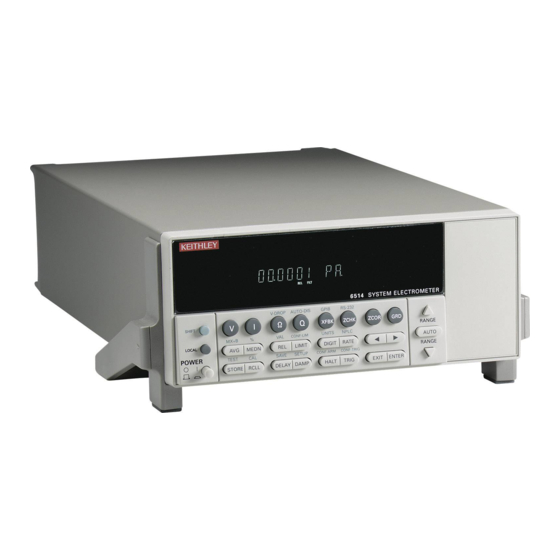
Page 27: Front And Rear Panel Familiarization
Use to select a shifted function or operation. LOCAL Cancels GPIB remote mode. POWER Power switch. In position turns 6514 on (I), out position turns it off (O). 2 Function and operation keys Top Row Unshifted Selects voltage measurement function. - Page 28 DELAY Sets user delay between trigger and measurement. DAMP Enables/disables damping for current measurements. HALT Stops measurement process. Puts 6514 in idle state. TRIG Trigger measurement(s). Takes 6514 out of idle state. EXIT Cancels selection, moves back to measurement display.
- Page 29 Getting Started 4 Display annunciators * (asterisk) Readings being stored in buffer. ↔ (more) Indicates additional selections are available. AUTO Autorange enabled. BUFFER Recalling readings stored in buffer. Questionable reading, or invalid cal step. FAST Fast (0.1 PLC) reading rate selected. FILT Filter enabled.
-
Page 30: Rear Panel Summary
Use as input low, or the common for the 2V Analog Output and Preamp Out. 5 CHASSIS This terminal is connected to the chassis of Model 6514 and to power line earth ground via the power line cord. For floating measurements (up to 500V peak), remove the ground link between COMMON... - Page 31 Getting Started 6 IEEE-488 Connector for IEEE-488 (GPIB) operation. Use a shielded cable, such as Models 7007-1 and 7007-2. 7 DIGITAL I/O Male DB-9 connector for digital output lines and component handler signals. 8 TRIGGER LINK Eight-pin micro-DIN connector for sending and receiving trigger pulses among connected instru- ments.
-
Page 32: Power-Up
Getting Started Power-up Line power connection Perform the following procedure to connect Model 6514 to line power and turn on the instrument. Check to be sure the line voltage setting on the power module is correct for the operating voltage in your area. The line voltage setting is indicated in the window on the power module (see Figure 1-2). -
Page 33: Power-Up Sequence
The following power-up sequence occurs when the Model 6514 is turned on: The Model 6514 performs self-tests on its EPROM and RAM with all digits and annun- ciators turned on. If a failure is detected, the instrument momentarily displays an error message and the ERR annunciator turns on. -
Page 34: Display
Appendix B. Default settings Model 6514 can be restored to one of five default setup configurations; factory (FACT), GPIB and three user-saved (USR0, USR1 and USR2). As shipped from the factory, Model 6514 pow- ers up to the factory default settings. Factory default settings provide a general purpose setup for front panel operation, while the GPIB default settings do the same for remote operation. -
Page 35: Table 1-2 Default Settings
Restoring factory or GPIB default setups — The SYSTem:PRESet command returns Model 6514 to the factory defaults and the *RST command returns it to the GPIB defaults. The *RST command is documented in Section 14 and SYSTem:PRESet is covered in Section 16 (SYSTem Subsystem). - Page 36 1-14 Getting Started Table 1-2 (cont.) Default settings Setting Factory GPIB Limit Tests: Limit 1 and Limit 2: Disabled Disabled HI and LO Values 1, -1 1, -1 Digital Fail Output Patterns 15 Digital Output Pass Pattern Auto-Clear Delay 0.00010 sec 0.00010 sec Output Clear Pattern Line 4 Mode...
-
Page 37: Scpi Programming
(?) that follows the command word. A query command requests (que- ries) the programmed status of that command. When a query command is sent and Model 6514 is addressed to talk, the response message is sent to the computer. -
Page 38: Measurement Concepts
Measurement Concepts • Measurement overview — Explains the basic measurement capabilities of Model 6514. • Performance considerations — Covers a couple of considerations that affect overall performance; warm-up and autozero. • Connection fundamentals — Covers fundamental information about connecting test circuits to the electrometer. -
Page 39: Measurement Overview
Performance considerations Warm-up period Model 6514 can be used within one minute after it is turned on. However, the instrument should be turned on and allowed to warm up for at least one hour before use to achieve rated accuracy. If the instrument has been exposed to extreme temperatures, allow extra time for the internal temperature to stabilize. -
Page 40: Connection Fundamentals
‘ Enable autozero. Connection fundamentals The following provides important fundamental information on input connections to Model 6514. Typical connection drawings are included with the various measurement procedures pro- vided in subsequent sections of this manual. Input connector The rear panel INPUT connector is a 3-lug female triax connector that will mate to a cable... - Page 41 Measurement Concepts Input configurations As shown in Figure 2-1, the input connector can be configured in two ways. With guard off (Figure 2-1A), input low is connected to the inner shell of the connector. This configuration is used for Amps, Coulombs, unguarded Volts and unguarded Ohms measurements. With guard on (Figure 2-1B), the driven guard is connected to the inner shell of the triax con- nector.
-
Page 42: Low Noise Input Cables
Model 237-ALG-2 — This 2-meter low noise triax cable mates directly to the input con- nector of Model 6514. The other end is terminated with three alligator clips. The clip with the red boot is input high, black boot is input low or guard, and the green boot is chassis ground. -
Page 43: Basic Connections To Dut
Measurement Concepts Basic connections to DUT Unguarded connections Basic unguarded connections are shown in Figure 2-3, the DUT is the voltage, current, resis- tance or charge to be measured. Circuit high is connected to the center conductor of the input connector and circuit low is connected to the inner shell of the connector. -
Page 44: Figure 2-4 Shielding For Unguarded Measurements
Measurement Concepts Noise and safety shields — Figure 2-4 shows typical shielding for unguarded measure- ments. A noise shield is used to prevent unwanted signals from being induced on the electrom- eter input. Measurements that may benefit from effective shielding include unguarded volts and ohms, amps below 1uA, and low level coulombs. - Page 45 Measurement Concepts Guarded connections The basic guarded connections for volts and ohms are shown in Figure 2-5. For these mea- surements, circuit high is connected to the center conductor of the input connector while circuit low is connected to the COMMON banana jack terminal. With guard (GRD) on, the driven guard is available at the inner shell of the triax connector which is connected to the metal guard plate.
-
Page 46: Test Fixture
The chassis of the test fixture should be metal so that it can function as a shield for the DUT or test circuit. The metal chassis should be connected to chassis ground of Model 6514 via the triax cable. •... - Page 47 2-10 Measurement Concepts Connectors, terminals and internal wiring Basic connector requirements include a 3-lug female triax connector, and three banana jacks. One banana jack is used to make the COMMON connection to the electrometer for guarded measurements. The other two banana jacks will accommodate connection to an external power supply.
-
Page 48: Input Protection
Under Test 6514 Ammeter Floating measurements With the ground link between the COMMON and CHASSIS banana jack terminals removed, Model 6514 can perform floating measurements up to 500V above chassis ground. These mea- surements can result in safety concerns. -
Page 49: Figure 2-9 Floating Measurements
2-12 Measurement Concepts Figure 2-9 shows two examples where Model 6514 floats at a hazardous voltage level. In Fig- ure 2-9A, a shock hazard (100V) exists between meter input LO and chassis ground. If meter input LO is connected to a noise shield, then the shock hazard will also be present on that shield. -
Page 50: Zero Check And Zero Correct
Measurement Concepts 2-13 Zero check and zero correct Table 2-3 lists the display messages associated with zero check and zero correct. The two-character message is displayed along with the reading. Table 2-3 Display messages for zero check and zero correct Display Message Zero Check Zero Correct... -
Page 51: Zero Correct
= 10pF Amps Zero correct Model 6514 has a zero correct feature to algebraically subtract the voltage offset term from the measurement. Perform the following steps to zero correct the volts or amps function: NOTE The ZCOR key toggles zero correct on and off. If zero correct is enabled (“ZZ” or “CZ”... -
Page 52: Scpi Programming - Zero Check And Zero Correct
Model 6514 will remain zeroed even if it is upranged. If downranged, re-zero the instrument. Model 6514 does not have to be re-zeroed as long as the ambient temperature remains stable. Zero correction cancels the voltage offset term of the amplifier. With both zero check and zero correct enabled, the instrument may not display a perfectly zeroed reading. - Page 53 2-16 Measurement Concepts B) SYSTem:ZCORrect:ACQuire The zero correct value can only be acquired while zero check is enabled. The internal offset will become the correction value. Zero correction can then be performed with zero check dis- abled. This acquire method makes it convenient if you need to re-zero the selected function often.
-
Page 54: Input Bias Current And Offset Voltage Calibration
Press ENTER. The instrument will prompt for the triax shielding cap as follows: INPUT CAP Connect a triax shielding cap to the rear panel INPUT jack. (Use a Keithley CAP-31 or equivalent.) Press ENTER to complete input bias current calibration. -
Page 55: Scpi Programming
Input bias current calibration. :CALibration:UNPRotected:VOFFset Offset voltage calibration. SCPI command input bias current calibration Connect a triax shielding cap to the rear panel INPUT jack. (Use a Keithley CAP-31 or equivalent.) Send the following command to perform input bias current calibration: :CAL:UNPR:IOFF Allow the Model 6514 to complete the calibration process. -
Page 56: Measurement Considerations
Offset current of Model 6514 could affect low current measurements. Voltage burden Offset voltage of Model 6514 could cause errors if it is high in relation to the voltage of the measured circuit. Noise Noise generated by source resistance and source capacitance. - Page 57 2-20 Measurement Concepts Table 2-6 (cont.) Summary of measurement considerations Considerations Description For all measurements: See Appendix C for details Ground loops Multiple ground points can create error signals. Triboelectric effects Charge currents generated in a cable by friction between a conductor and the surrounding insulator (i.e.
-
Page 58: Volts And Ohms Measurements
Volts and Ohms Measurements Measurement overview — Summarizes the volts and ohms measurement capabilities of • Model 6514. Guarding — Explains guarding and the benefits derived from it for high-impedance • volts and ohms measurements. • Volts and ohms measurement procedure — Provides the procedure to measure volts and ohms. -
Page 59: Measurement Overview
Volts and Ohms Measurements Measurement overview Volts measurements — Model 6514 can make volts measurements from 10µV to 210V using three measurement ranges; 2V, 20V, and 200V. Ohms measurements — Model 6514 makes ohms measurements by sourcing a test current and measuring the voltage drop across the DUT. -
Page 60: Input Cable Leakage And Capacitance
Volts and Ohms Measurements Figure 3-1 Insulator (one of two) High-impedance 6514 voltage measurements Leakage Path COMMON Metal Mounting Plate GRD Disabled A. Unguarded Insulator (one of two) 6514 COMMON Metal Mounting Plate GRD Enabled B. Guarded Input cable leakage and capacitance In a similar manner to leakage in the test circuit, leakage in the input cable could also corrupt high-impedance measurements. -
Page 61: Volts And Ohms Measurement Procedure
Volts and Ohms Measurements Volts and ohms measurement procedure CAUTION The maximum input voltage to Model 6514 is 250V peak. Exceeding this value may cause damage to the instrument that is not covered by the warranty. WARNING The maximum common-mode input voltage, which is the voltage between the input (HI or LO) and chassis ground, is 500V peak. -
Page 62: Figure 3-2 Connections For Unguarded Volts And Ohms
TRIGGER LINK RS232 LINE RATING 50, 60Hz INPUT PREAMP 60 VA MAX PREAMP FUSE LINE 2V ANALOG GUARD 630mA 100 VAC OUTPUT (FOLLOWS (SB) 120 VAC GUARD INPUT) (PROGRAMMABLE) 220 VAC 315mAT (INTERNAL) 240 VAC (SB) 6514 Rear Panel GRD Disabled... -
Page 63: V-Drop And I-Source For Ohms
Disable zero check and take a reading from the display V-Drop and I-Source for ohms Model 6514 performs ohms measurement by sourcing a known test current through the DUT and then measuring the voltage drop across it. The resistance reading is then calculated... -
Page 64: Scpi Programming
Volts and Ohms Measurements While the electrometer is measuring ohms, the test current through the DUT and the voltage drop across it can be displayed as follows: V-Drop — While displaying an ohms reading, press SHIFT and then Ω to display the voltage drop across the DUT. -
Page 65: Programming Example
To return a fresh (new) reading, you can send the INITiate command to trigger one or more readings before sending :DATA?. Details on INITiate are provided in Section 9. While Model 6514 is busy performing measurements, the :DATA? command will not return the reading string until the instrument finishes and goes into the idle state. -
Page 66: Volts And Ohms Measurement Considerations
) must be about 1000 times the value of the source resistance (R ). The input resistance of Model 6514 is >200TΩ. Therefore, to keep the error under 0.1%, the source resis- tance of the measured voltage must be <200GΩ. -
Page 67: Input Capacitance (Settling Time)
In both cases, the shunt capacitance (C) has to fully charge before an accurate voltage mea- surement can be made by V of Model 6514. The time period for charging the capacitor is deter- τ mined by the RC time constant (one time constant, = RC), and the familiar exponential curve of Figure 3-6 results. -
Page 68: Figure 3-5 Effects Of Input Capacitance
Volts and Ohms Measurements 3-11 Figure 3-5 Effects of input capacitance 6514 Measured Voltmeter Source τ = RC A. High-Impedance Volts Measurement (Unguarded) 6514 Measured Ohmmeter Resistance τ = RC B. High-Impedance Ohms Measurement (Unguarded) -
Page 69: Guarding Input Cable
If R is large enough, the divider will significantly atten- uate the voltage seen at the input of Model 6514 (see “Cable Leakage Resistance”). Also, R the cable capacitance (C ) could create a long RC time constant resulting in a slow measurement response (see “Input Capacitance”). -
Page 70: Figure 3-8 Guarded Input Cable
, there is no capacitor charging process to slow down the measurement response. For the volts and ohms functions, the input of Model 6514 places the driven guard on the inner shield of the triax cable when GRD is enabled. -
Page 71: Application
The test circuit in Figure 3-9A uses Keithley Model 230 as a voltage source and Model 6514 to perform the voltage measurements. Figure 3-9B shows the voltage waveform across the capacitor during the three phases of the test. -
Page 72: Figure 3-9 Measuring Dielectric Absorption
Volts and Ohms Measurements 3-15 Figure 3-9 Measuring dielectric absorption VOLTAGE SOURCE 6514 VOLTMETER A. Connections Discharge Soak Recovery Time B. Voltage Waveform... -
Page 73: Amps Measurements
Amps Measurements • Measurement overview — Summarizes the current measurement capabilities of Model 6514. • Amps measurement procedure — Provides the procedure to measure amps. High-Impedance measurement techniques — Explains non-driven guarding tech- • niques to eliminate leakage currents in high-impedance test circuits. -
Page 74: Measurement Overview
10 measurement ranges; 20pA, 200pA, 2nA, 20nA, 200nA, 2µA, 20µA, 200µA, 2mA, and 20mA. External feedback — The external feedback mode of Model 6514 can be used to measure logarithmic currents, and re-configure the input to use non-decade current ranges. Measure- ments using the external feedback mode are covered in Section 11. - Page 75 Amps Measurements Step 2 Perform zero correction To achieve optimum accuracy for low current measurements, it is recommended that you zero correct the electrometer. To do so, select the 20pA range (which is the lowest range) and press the ZCOR key until the “ZZ” message is displayed. See Section 2 for details on zero correction. Step 3 Select a manual measurement range or enable auto range Use the RANGE...
-
Page 76: Damping
315mAT (INTERNAL) 240 VAC (SB) 6514 Rear Panel Step 5 Disable zero check and take a reading from the display If the readings are noisy, you may want to use damping and/or filtering to reduce noise. Use filtering if the noise is caused by a noisy input signal and use damping if noise is caused by input capacitance. -
Page 77: High Impedance Measurement Techniques
4-2B, the leakage current (I ) is shunted to ammeter input LO and is not measured by the amme- ter. Therefore, the ammeter only measures I Figure 4-2 High impedance current measurements 6514 Metal Mounting Plate Insulators A. Unguarded 6514 Metal Guard Plate *R = ≥1GΩ... - Page 78 10V is dropped by R . The current through R will be approximately 10nA (10V/1GΩ = 10nA). Therefore, the current that is measured by Model 6514 is the sum of the two currents (I = I +10nA). Obviously, if I is a low level current, then the 10nA leakage will corrupt the measurement.
-
Page 79: Figure 4-3 Floating Current Measurements
Amps Measurements Figure 4-3 +10V Floating current 6514 measurements I = I + 10nA = 10nA 1GΩ 1GΩ A. Unguarded 6514 +10V I = I + <2pA <2mV = <2pA 1GΩ 1GΩ = 10nA 1GΩ 1GΩ B. Guarded... -
Page 80: Scpi Programming
To return a fresh (new) reading, you can send the INITiate command to trigger one or more readings before sending :DATA?. Details on INITiate are provided in Section 9. While Model 6514 is busy performing measurements, the :DATA? command will not return the reading string until the instrument finishes and goes into the idle state. -
Page 81: Programming Example
The input bias current for Model 6514 is listed in the specifications. Input bias current may be reduced by performing the current offset correction procedure explained in Section 19. -
Page 82: Noise
) due to voltage burden can be calculated as follows: 100% %error -------------------- - The voltage burden of Model 6514 depends on the selected range (see specifications). Voltage burden may be reduced by performing the offset correction procedure in Section 19. Figure 4-4 Source... -
Page 83: Figure 4-5 Source Resistance And Capacitance
Table 4-2 Minimum recommended source resistance values Minimum Recommended Range Source Resistance 1GΩ to 100GΩ 1MΩ to 100MΩ µA 1kΩ to 100kΩ 1Ω to 100Ω Figure 4-5 Source resistance and capacitance noise Current Source Model 6514 Ammeter... - Page 84 Amps Measurements Source capacitance DUT source capacitance will also affect the noise performance of the Model 6514 ammeter. In general, as source capacitance increases, the noise also increases. To see how changes in source capacitance can affect noise gain, again refer to the simplified ammeter model in Figure 4-5.
-
Page 85: Applications
To ensure that the voltage is settled before each current measurement, you can program Model 6514 for a delay. For example, if you program Model 6514 for a one second delay, each mea- surement will be performed after the voltage step is allowed to settle for one second. The current measurements can be stored in the buffer. -
Page 86: Capacitor Leakage Current
Equivalent Circuit Cable insulation resistance NOTE For this test, Model 6514 uses the source voltage, measure current method to determine resistance. Once a current measurement is performed, resistance can be calculated. Figure 4-8 shows how to measure the insulation resistance of a cable. The resistance of the insulator between the shield and the inner conductor is being measured. -
Page 87: Figure 4-9 Connections; Surface Insulation Resistance Test
4-15 Surface insulation resistance (SIR) NOTE For this test, Model 6514 uses the source voltage, measure current method to determine resistance. Once a current measurement is performed, resistance can be calculated. Figure 4-9 shows how to measure the insulation resistance between PC board traces. Note that the drawing shows a "Y"... -
Page 88: Coulombs Measurements
• Measurement overview — Summarizes the charge measurement capabilities of the Model 6514. • Auto discharge — Explains how to use the auto discharge feature of Model 6514. • Coulombs measurement procedure — Provides the procedure to measure coulombs. •... -
Page 89: Measurement Overview
Q is the charge The voltage is scaled and displayed as charge. External feedback — The external feedback mode of Model 6514 can be used to measure non-standard charge ranges. Measurements using the external feedback mode are covered in Section 11. -
Page 90: Coulombs Measurement Procedure
Coulombs Measurements Coulombs measurement procedure CAUTION The maximum input voltage and current to Model 6514 is 250V peak and 21mA. Exceeding either of these values may cause damage to the instru- ment that is not covered by the warranty. WARNING The maximum common-mode input voltage, which is the voltage between the input (HI or LO) and chassis ground, is 500V peak. -
Page 91: Figure 5-1 Typical Connections For Coulombs
220 VAC (INTERNAL) 240 VAC (SB) 6514 Rear Panel Step 7 Take the charge reading from the display If using auto discharge, use the REL key to zero the display when the integrator resets. Remember that Rel was enabled in Step 5. Therefore, you will have to press REL twice. The first press disables Rel, and the second press re-enables it to zero the display. -
Page 92: Table 5-1 Scpi Commands — Coulombs Function
To return a fresh (new) reading, you can send the INITiate command to trigger one or more readings before sending :DATA?. Details on INITiate are provided in Section 9. While Model 6514 is busy performing measurements, the :DATA? command will not return the reading string until the instrument finishes and goes into the idle state. -
Page 93: Programming Example
Any such current is integrated along with the input signal and reflected in the final reading. Model 6514 has a maximum input bias of 4fA for charge at T (temperature at time of calibration). This input offset translates into a charge of 4fC per second at the T temperature. -
Page 94: Zero Check Hop And Auto Discharge Hop
R2 that will limit current to ≤20mA. When switch S1 is closed, the Keithley Model 230 voltage source charges the capacitor. After waiting sufficient time for the capacitor to fully charge, open switch S1 and close switch S2 to measure the charge. -
Page 95: Range, Units, Digits, Rate, And Filters
Range, Units, Digits, Rate, and Filters • Range, units, and digits — Provides details on measurement range, reading units, and display resolution selection. Includes the SCPI commands for remote operation. Rate — Provides details on reading rate selection. Includes the SCPI commands for •... -
Page 96: Range, Units, And Digits
Range, Units, Digits, Rate, and Filters Range, units, and digits Range The ranges for each measurement function are listed in Table 6-1. The range setting (fixed or AUTO) is remembered by each function. Table 6-1 Measurement ranges Ω 20pA 2kΩ 20nC 200pA 20kΩ... - Page 97 Range, Units, Digits, Rate, and Filters Every time an autorange occurs, a search for every available range of the selected function is performed. The time it takes to perform the search could slow down range change speed signif- icantly. For V, I and ( measurements, upper and/or lower autorange limits can be set to reduce search time.
-
Page 98: Units
2. Scientific notation provides more resolution on small values than engineering units. Digits The DIGIT key sets display resolution for Model 6514. Display resolution can be set from to 6 digits. This single global setting affects display resolution for all measurement functions. - Page 99 7 = 6 -digit resolution Note: Rational numbers can be used. For example, to set 4 resolution, send a value of 4.5 (the 6514 rounds it to 5). Note: *RST default is ON and SYSTem:PRESet default is OFF. Programming example — range and digits...
-
Page 100: Rate
In general, Model 6514 has a parabola-like shape for its speed vs. noise characteristics and is shown in Figure 6-1. Model 6514 is optimized for the 1 PLC to 10 PLC reading rate. At these speeds (lowest noise region in the graph), Model 6514 will make corrections for its own internal drift and still be fast enough to settle a step response <100ms. -
Page 101: Scpi Programming - Rate
Range, Units, Digits, Rate, and Filters NPLC Menu — From this menu you can set rate by setting the PLC value. Perform the fol- lowing steps to set NPLC: Press SHIFT and then NPLC to display the present PLC value. Use the , , , and keys to display the desired PLC value (0.01 to 10). -
Page 102: Filters
Range, Units, Digits, Rate, and Filters Filters Filtering stabilizes noisy measurements caused by noisy input signals. The Model 6514 uses two types of filters: median and digital. The displayed, stored or transmitted reading is simply the result of the filtering processes. Note that both the median and digital filters can be in effect at the same time. -
Page 103: Digital Filter
Range, Units, Digits, Rate, and Filters Digital filter Figure 6-2 Digital filter Conversion Conversion Conversion types; moving and repeating Reading Reading Reading Conversion Conversion Conversion A. Class - Average, Readings = 10, Type - Moving Conversion Conversion Conversion Reading Reading Reading Conversion Conversion... -
Page 104: Scpi Programming - Filters
6-10 Range, Units, Digits, Rate, and Filters Operation consideration • The digital filter operation will reset (start over) whenever the zero check operation is performed or the function is changed. Digital filter configuration and control The AVG key is a toggle-action key. It will either disable the digital filter (display “AVER- AGE OFF”), or access the configuration menu to enable the digital filter. - Page 105 Range, Units, Digits, Rate, and Filters 6-11 Programming example The following command sequence configures and enables both filters: ‘ Median Filter: MED:RANK 5 ‘ Set rank to 5. MED ON ‘ Enable median filter. ‘ Digital Filter: AVER:COUN 20 ‘ Set filter count to 20. AVER:TCON MOV ‘...
-
Page 106: Relative, Mx+B And Percent (%)
Relative, mX+b and Percent (%) • Relative — Explains how to null an offset or establish a baseline value. Includes the SCPI commands for remote operation. • mX+b and percent (%) — Covers these two basic math operations, and includes the SCPI commands for remote operation. -
Page 107: Relative
Rel’ed reading. However, this does not increase the maximum allowable input for that range. An over-range input signal will still cause the display to overflow. For example, on the 20V range, Model 6514 still overflows for a 20.1V input. NOTE Rel can be used on the result of the percent (%) or mX+b calculations. -
Page 108: Scpi Programming - Relative
Relative, mX+b and Percent (%) VAL key The SHIFT-VAL key sequence displays the present Rel value. From this display you can enable Rel using that Rel value or you can key in a different Rel value. Press SHIFT and then VAL to display the present Rel value. To change the Rel value, use the , , and keys to change the value. -
Page 109: Mx+B And Percent (%)
Relative, mX+b and Percent (%) A) :FEED <name> Specify reading to Rel With SENSe[1] selected, the Rel operation will be performed on the input signal. With CALCulate[1] selected, the Rel operation will be performed on the result of the Percent (%) or mX+b calculation. -
Page 110: Percent (%)
Relative, mX+b and Percent (%) on the range symbol and use the keys. With the cursor on the polarity sign, the keys toggle polarity. NOTE Range symbols are defined in Table 7-1 Press ENTER to enter the M value and display the offset (B) value: B: +00.000000 P (factory default) Key in the offset value. -
Page 111: Scpi Programming - Mx+B And Percent
Relative, mX+b and Percent (%) SCPI programming — mX+b and percent Table 7-3 SCPI commands — mX+b and percent Commands Description Default CALCulate[1] CALCulate1 Subsystem: :FORMat <name> Select calculation; MXB or PERCent. :KMATh Path to configure mX+b and percent: :MMFactor <n> Specify scale factor (M) for mX+b;... -
Page 112: Buffer
Buffer • Buffer operations — Explains how to store and recall readings including buffer statistics. • SCPI programming — Covers the SCPI commands used to control buffer operations. -
Page 113: Buffer Operations
Buffer Buffer operations Model 6514 has a buffer to store from one to 2500 readings. It also stores overflow readings. Each reading has a timestamp. The timestamp for each reading is referenced to the time the measure/store process is started. In addition, recalled data includes statistical information (maximum, minimum, peak-to-peak, average and standard deviation). -
Page 114: Buffer Statistics
Buffer Figure 8-1 Buffer locations Reading Value Timestamp Reading Value Timestamp Reading Value Timestamp Reading Value Timestamp Reading Value Timestamp Reading Value Timestamp Reading Value Timestamp Reading Value Timestamp Reading Value Timestamp RANGE Reading Value Timestamp Standard Deviation Value RANGE Average Average Value Pk-Pk... -
Page 115: Scpi Programming
TRACe:DATA? (which is the command to read the buffer). The CALCulate3 commands are used to obtain statistics from the buffer data. NOTE The Model 6514 uses IEEE-754 floating point format for statistics calculations. Table 8-1 SCPI commands — buffer Commands... - Page 116 Buffer B) TRACe:FEED <name> Name parameters: • SENSe — Raw input readings are stored in the buffer. • CALCulate1 — The results of the mX+b or percent (%) calculation are stored in the buffer. See Section 7 for information on mX+b and percent. •...
-
Page 117: Programming Example
If there is a lot of data in the buffer, some statistic operations may take too long and cause a bus time-out error. To avoid this, send calc3:data? and then wait for the MAV (message available) bit in the Status Byte Register to set before addressing the Model 6514 talk (see Section 13). -
Page 118: Triggering
SCPI programming — Includes the commands used to configure the trigger model, and the commands to control the measurement process. • External triggering — Explains external triggering which allows Model 6514 to trigger other instruments, and be triggered by other instruments. -
Page 119: Trigger Models
Triggering Trigger models The flowcharts in Figures 9-1 and 9-2 summarize triggering for Model 6514. They are called trigger models because they are modeled after the SCPI commands to control triggering (operation). Figure 9-1 Turn 6514 ON Trigger model —... -
Page 120: Figure 9-2 Trigger Model — Remote Operation
Trigger Delay TRIGger:DELay:AUTO <b> 0.0 sec MEASURE Action Note: The following commands place the Model 6514 into = GPIB Default idle: ABORt, *RST, SYSTem:PRESet, *RCL <NRf>, = Output Trigger DCL, and SDC. The only difference between front panel operation (Figure 9-1) and remote operation (Figure 9-2) is within the idle state of the instrument. -
Page 121: Idle And Initiate
Typically, operation remains in the arm and trigger layers of the trigger model. However, Model 6514 can be put into the idle state at any time by pressing the HALT key. To take the instrument out of idle, press the TRIG key. Other front panel keys can instead be pressed, but they may change the setup. - Page 122 Manual (ARM:SOURce MANual) — Event detection for the arm layer is satisfied by pressing the TRIG key. Model 6514 must be in the local mode for it to respond to the TRIG key. Press LOCAL or send LOCAL 14 over the bus to place Model 6514 in local.
-
Page 123: Figure 9-3 Measure Action Block Of Trigger Model
CONV = Reading Conversion Output triggers Model 6514 can send out an output trigger (via the rear panel TRIGGER LINK connector) right after the measure action and/or when operation leaves the trigger layer. An output trigger can be used to trigger another instrument to perform an operation (e.g., select the next output... -
Page 124: Trigger Model Configuration - Front Panel
Triggering Counters Programmable counters are used to repeat operations within the trigger model layers. For example, if the trigger count is set for 10, operation will keep looping around in the trigger layer until 10 measurements are performed. If the arm count is set to 2, operation will then loop back through the arm layer and go back into the trigger layer to perform 10 more measurements. - Page 125 Triggering • TRIG-OUT — Configure output triggers: LINE — Select the output trigger link line (1 to 6). VMC — Enable (ON) or disable (OFF) the VMC (voltmeter complete) output trigger. DELAY — Configure the trigger delay of the trigger layer: •...
-
Page 126: Scpi Programming
Triggering SCPI programming Table 9-2 SCPI commands — triggering Command Description Default Ref ABORt Reset trigger system (goes to idle state). INITiate Initiate one trigger cycle. FETch? Request latest reading. READ? Trigger and request a “fresh” reading. ARM[:SEQuence[1]] Arm Layer: [:LAYer[1]] :SOURce <name>... -
Page 127: Programming Example
When this action command is sent, any pending (latched) input triggers are cleared immedi- ately. When the Model 6514 is being latched by another instrument, it may inadvertently receive and latch input triggers that do not get executed. These pending triggers could adversely affect subsequent operation. -
Page 128: External Triggering
Triggering 9-11 External triggering Input and output triggers are received and sent via the rear panel TRIGGER LINK connector. The trigger link has six lines. At the factory, line #2 is selected for output triggers and line #1 is selected for input triggers. These input/output assignments can be changed as previously explained in this section. -
Page 129: Output Trigger Specifications
DUT connected to that channel. Such a test system is shown in Figure 9-7, which uses a Model 6514 to measure 10 DUTs switched by a Model 7011 multiplexer card in a Model 7001 or 7002 switch system. - Page 130 The trigger link connections for this test system are shown in Figure 9-8. The trigger link of Model 6514 is connected to the trigger link (IN or OUT) of the switching mainframe. Note that with the default trigger settings of the switching mainframe, line #1 is an input and line #2 is an output.
-
Page 131: Figure 9-9 Operation Model For Triggering Example
Made Scanned Measurements Channels Operation of Model 6514 starts at point A in the flowchart, where it waits for an external trigger. Pressing STEP takes Model 7001/2 out of idle and places operation at point B in the flowchart. For the first pass through Model, the scanner does not wait at point B. Instead, it closes the first channel (point C). -
Page 132: Limit Tests
Limit Tests • Limit testing — Explains the basic Limit 1 and Limit 2 testing operations. • Binning — Explains how to use a component handler to perform binning operations. • Front panel operation — Explains how to configure and run tests from the front panel. •... -
Page 133: Limit Testing
10-2 Limit Tests Limit testing As shown in Figure 10-1, there are two limit tests that can be performed on a DUT. Limit 1 is used as the wide pass band and Limit 2 is used as the narrow pass band. It is up to the user to specify limits that conform to this pass band relationship. -
Page 134: Figure 10-3 Operation Model For Limit Test
Limit Tests 10-3 A test is only performed if it is enabled. Therefore, you can perform a single-stage test or a 2-stage test. In the flowchart (Figure 10-3), operation simply proceeds through a disabled test. Figure 10-3 Start Operation model for limit test Measure Limit 1... -
Page 135: Binning
Even though no additional equipment is required to perform limit tests on the DUT, Model 6514 can be used with a component handler to perform binning operations. Based on the out- come of a test, the component handler will place the DUT in the assigned bin. -
Page 136: Figure 10-5 Operation Model For Limit Testing With Binning
Limit Tests 10-5 Figure 10-5 shows the basic limit testing flowchart expanded to include binning. Notice that there are five possible output patterns (one pass pattern and four fail patterns), but only one will be sent to the component handler for each DUT that is tested. Figure 10-5 Start Operation model... -
Page 137: Component Handler Interface
Input (SOT) SOT Strobe Line The digital I/O lines are available at the DB-9 connector on the rear panel of Model 6514. A custom cable using a standard female DB-9 connector is required for connection to Model 6514. Start of test The SOT (start of test) line of the Digital I/O is used to control the start of the testing process. -
Page 138: Component Handler Types
The handler decodes the bit pattern and places the DUT in the appropriate bin. Model 6514 can be used with either of the two basic types of handlers. When used with a cat- egory pulse handler, Model 6514 pulses one of the four handler lines. The handler then places the DUT into the bin assigned to the pulsed line. -
Page 139: Digital Output Clear Pattern
4 is HI and busy state is LO. When using a catagory register component handler, Model 6514 must be set for the End of Test mode. In this mode, Model 6514 sends the EOT pulse to the component handler as previ- ously explained. - Page 140 Limit Tests 10-9 Auto-Clear timing — The following example timing diagram (Figure 10-7) and discussion explain the relationship between the digital output lines for auto-clear. Figure 10-7 SOT* Digital output auto-clear timing Line 1 example Line 2 Line 3 Line 4 10µs Delay 10µs...
-
Page 141: Front Panel Operation
10-10 Limit Tests Front panel operation Limit test configuration Most aspects of limit testing are configured from the limit configuration menu. When using a component handler, the “start of test” (/STest, Test or Immediate) option is set from the arm layer configuration menu. -
Page 142: Perform Limit Tests
• LIN4MOD (Line 4 Mode): ENDOFTST (End of Test) — With this mode, Model 6514 will pulse the EOT line when the test is finished. Use with catagory register component handlers. /BUSY and BUSY — Pulls line 4 LO (/Busy) or HI (Busy) while the test is in pro- cess. -
Page 143: Scpi Programming
10-12 Limit Tests SCPI programming Table 10-2 SCPI commands — limit tests Command Description Default Ref :CALCulate2 CALCulate2 Subsystem: :FEED <name> Select input path for limit testing; CALCulate[1] SENS or SENSe[1]. :LIMit[1] Limit 1 Testing: :UPPer Configure upper limit: [:DATA] <n> Set limit;... - Page 144 Limit Tests 10-13 Table 10-2 (cont.) SCPI commands — limit tests Command Description Default Ref :SOURce2 SOURce2 Subsystem: :TTL <NDN> or <NRf> Specify 4-bit digital output clear pattern. :CLEar Clear I/O port (return output to TTL pattern): [:IMMediate] Clear I/O port immediately. :AUTO <b>...
- Page 145 10-14 Limit Tests be 1011. To use one of the other formats, convert the binary number to its decimal, hexadecimal, or octal equivalent: Binary 1011 = Decimal 11 = Hexadecimal B = Octal 13 The <NDN> (non-decimal numeric) parameter type is used to send non-decimal values. These values require a header (#B, #H or #Q) to identify the data format being sent.
-
Page 146: Programming Example
Limit Tests 10-15 Programming example The following command sequence will test DUT using the limit tests example shown in Fig- ure 10-2. *RST ‘ Restore RST defaults (Volts function). CALC2:LIM:UPP 2 ‘ Set upper limit for Limit 1 (2V). CALC2:LIM:LOW -2 ‘... -
Page 147: Digital I/O, Analog Outputs, And External Feedback
Digital I/O, Analog Outputs, and External Feedback • Digital I/O port — Explains how to use the digital I/O port to control external circuitry. • Analog outputs — Covers the 2V analog output and preamp out. • External feedback — Explains how to use the external feedback mode to perform charge and current measurements. -
Page 148: Digital I/O Port
Component handler control — When performing limit tests, a component handler can be used to sort DUT into bins. The digital I/O of Model 6514 serves as the interface between the limit tests and the component handler. Via the digital input line (pin 6), the component handler can tell Model 6514 when it is ready for the test. -
Page 149: Sink Mode - Controlling External Devices
Digital I/O, Analog Outputs, and External Feedback 11-3 NOTE Information on using the digital I/O to control a component handler for limit tests is provided in Section 10. • External device control — Each digital output can be used as a control switch for an external device (i.e. -
Page 150: Figure 11-3 Controlling Externally Powered Relays
In the HI state, the output transistor is off (transistor switch open). This interrupts current flow through the external device. Figure 11-3 Controlling externally powered relays Model 6514 Pin 5 - External Voltage Flyback Connection To other three digital outputs External Power... -
Page 151: Source Mode - Logic Control
Each output line can source up to 2mA. Exceeding 2mA may cause damage Model 6514 that is not covered by the warranty. Figure 11-4 shows how to connect a logic device to one of the output lines. When the output line is set HI, the transistor will turn off (transistor switch open) to provide a reliable logic high output (>3.75V). -
Page 152: Scpi Programming - Digital Output Pattern
11-6 Digital I/O, Analog Outputs, and External Feedback Perform the following steps to set the digital output pattern from the front panel: Press SHIFT and then CONF-LIM to access the limits menu. Press the until “LIMIT:PASS” is displayed. Press ENTER. The present digital output pattern value will be displayed. Use the , , and keys to display the desired output pattern value (0 to 15), and press ENTER. -
Page 153: Analog Outputs
11-7 Analog outputs Model 6514 has two analog outputs on the rear panel. The 2V ANALOG OUTPUT provides a scaled ±2V output with a value of ±2V corresponding to full-range input. The PREAMP OUT is especially useful in situations requiring buffering. These two analog outputs are discussed in the following paragraphs. -
Page 154: Figure 11-5 Typical 2V Analog Output Connections
B. Equivalent Circuit Preamp out The preamp output of Model 6514 follows the signal amplitude applied to the input terminal The preamp output provides a guard output for volts measurements. It can be used as an invert- ing output or with external feedback in the amps and coulombs modes. Connections and equiv- alent circuits for the preamp output are shown in Figure 11-6. -
Page 155: Figure 11-6 Typical Preamp Out Connections
(SB) 120 VAC GUARD INPUT) (PROGRAMMABLE) 315mAT 220 VAC (INTERNAL) (SB) 240 VAC Model 1683 Test Lead kit Model 6514 Rear Panel Measuring Device (i.e. Chart recorder) A. Connections = -I Preamp Out Preamp Out Common Common 0.1Ω 0.1Ω Volts... -
Page 156: Table 11-3 Full-Range Preamp Out Values
100k. CAUTION To prevent damage to Model 6514, do not connect a device to preamp out that will draw more than ±100µA. For example, at 200V, the impedance connected to preamp out must be at least 2MΩ (200V/100µA = 2MΩ). -
Page 157: External Feedback
11-11 External feedback The external feedback function provides a means to extend the capabilities of Model 6514 electrometer to such uses as logarithmic currents, non-decade current ranges, as well as non- standard coulombs ranges. The following paragraphs discuss the basic electrometer input cir- cuitry and methods to implement these functions. -
Page 158: Shielded Fixture Construction
11-12 Digital I/O, Analog Outputs, and External Feedback Figure 11-7 Electrometer input circuitry (external feedback mode) Zero Check Op Amp To Ranging 100MΩ Amplifier Input <1Ω Common Preamp Out (Chassis) Shielded fixture construction Since shielding is so critical for proper operation of external feedback, it is recommended that a shielded fixture similar to the one shown in Figure 11-8 be used to house the feedback element. -
Page 159: Non-Standard Coulombs Ranges
C = the capacitance in farads V = the voltage in volts. Model 6514 display will read the charge directly in units determined by the value of C. For example, a 10µF capacitor will result in a displayed reading of 10µC/V. -
Page 160: Figure 11-8 Shielded Fixture Construction
Digital I/O, Analog Outputs, and External Feedback Figure 11-8 Input LO (Inner Shield) Shielded fixture Input HI (Center Conductor) construction Solder Lug From Signal To 6514 input Feedback Element To Preamp Out A. Construction Feedback Element Preamp Out To Ranging... -
Page 161: Logarithmic Currents
Figure 11-9. Analyzing the transistor in this configuration leads to the relationship: V = kT/q[ln(I/I ) - ln(h /(1 + h where; h is the current gain of the transistor. Model 6514 Figure 11-9 “Transdiode” logarithmic current Zero configuration Check Input 10MΩ... -
Page 162: Non-Decade Current Gains
PNP transistor for Q1. Non-decade current gains Model 6514 electrometer input uses internal decade resistance feedback networks for the current ranges. In some applications, non-decade current gains may be desirable. As shown in Figure 11-10, an external feedback resistor, R , can be used to serve this purpose. -
Page 163: Scpi Programming - External Feedback
SYSTem Subsystem: :ZCHeck <b> Enable or disable zero check. Sec 2 Programming example — external feedback The following command sequence configures Model 6514 to perform measurements using the external feedback mode: SYST:ZCH ON ‘ Enable zero check. VOLT:XFE ON ‘ Enable external feedback. -
Page 164: Remote Operation
Remote Operation • Selecting and configuring an interface — Explains how to select and configure an interface; GPIB or RS-232. • GPIB operation and reference — Covers the following GPIB topics: GPIB Bus Standards GPIB Bus Connections Primary Address Selection General Bus Commands Front Panel GPIB Operation Programming Syntax... -
Page 165: Selecting And Configuring An Interface
GPIB interface — The GPIB is the IEEE-488 interface. Model 6514 must be assigned to unique address. At the factory the address is set to 14, but can be set to any value from 0 to 30. - Page 166 Remote Operation 12-3 NOTE When an interface is enabled (on) or disabled (off), the instrument will exit from the menu structure and perform the power-on sequence. GPIB interface The GPIB interface is selected and configured from the GPIB menu structure. From this menu, you can enable or disable the GPIB interface, and check or change the following settings: •...
- Page 167 12-4 Remote Operation NOTE See “RS-232 Interface Reference” (located at the end of this section) for information on these settings and connections to the computer. Selecting RS-232 interface — Press SHIFT and then RS-232 to access the RS-232 menu. The present status (on or off) of the RS-232 interface is displayed. If it is already enabled (on), proceed to step 1 of “Checking/Changing RS-232 Settings”...
-
Page 168: Gpib Operation And Reference
IEEE-488.2-1992 and defines a standard set of commands to control every programmable aspect of an instrument. GPIB bus connections To connect Model 6514 to the GPIB bus, use a cable equipped with standard IEEE-488 con- nectors as shown in Figure 12-1. Figure 12-1 IEEE-488 connector To allow many parallel connections to one instrument, stack the connector. -
Page 169: Figure 12-2 Ieee-488 Connections
IEEE-488 connections Controller To avoid possible mechanical damage, stack no more than three connectors on any one unit. NOTE To minimize interference caused by electromagnetic radiation, use only shielded IEEE-488 cables. Available shielded cables from Keithley are Models 7007-1 and 7007-2. -
Page 170: Primary Address Selection
Not observing these limits may cause erratic bus operation. Primary address selection Model 6514 ships from the factory with a GPIB address of 14. When the instrument powers up, it momentarily displays the primary address. You can set the address to a value of 0-30. Do not assign the same address to another device or to a controller that is on the same GPIB bus. -
Page 171: General Bus Commands
Serial polls Model 6514. REN (remote enable) The remote enable command is sent to Model 6514 by the controller to set up the instrument for remote operation. Generally, the instrument should be placed in the remote mode before you attempt to program it over the bus. Simply setting REN true does not actually place the instru- ment in the remote state. - Page 172 DCL. GET (group execute trigger) GET is a GPIB trigger that is used as an event to control operation. Model 6514 reacts to this trigger if it is the programmed control source. The control source is programmed from the SCPI TRIGger subsystem.
-
Page 173: Front Panel Gpib Operation
IFC (Interface Clear) command. • LSTN — This indicator is on when Model 6514 is in the listener active state, which is activated by addressing the instrument to listen with the correct MLA (My Listen Address) command. LSTN is off when the unit is in the listener idle state. Place the unit in the listener idle state by sending UNL (Unlisten), addressing it to talk, or sending the IFC (Interface Clear) command over the bus. -
Page 174: Programming Syntax
Remote Operation 12-11 Programming syntax The following paragraphs cover syntax for both common commands and SCPI commands. For more information, see the IEEE- 488.2 and SCPI standards. Command words Program messages are made up of one or more command words. Commands and command parameters Common commands and SCPI commands may or may not use a parameter. - Page 175 12-12 Remote Operation <NDN> Non-decimal numeric — A non-decimal value that can be used to program status enable registers. A unique header identifies the format; #B (binary), #H (hexadecimal) and #Q (octal). See “Programming Enable Registers” in Section 13 for details. *SRE #B10001 Set bits B0 and B4 of Service Request Enable Register...
- Page 176 Remote Operation 12-13 Case sensitivity Common commands and SCPI commands are not case sensitive. You can use upper or lower case and any case combination. Examples: *RST = *rst :DATA? = :data? :SYSTem:PRESet = :system:preset Long-form and short-form versions A SCPI command word can be sent in its long-form or short-form version. The command tables in this manual use the long-form version.
- Page 177 12-14 Remote Operation Program messages A program message is made up of one or more command words sent by the computer to the instrument. Each common command is simply a three letter acronym preceded by an asterisk (*). The following SCPI commands from the STATus subsystem are used to help explain how command words are structured to formulate program messages.
- Page 178 Remote Operation 12-15 Command path rules • Each new program message must begin with the root command, unless it is optional (e.g., [:SENSe]). If the root is optional, simply treat a command word on the next level as the root. •...
- Page 179 Sending a response message After sending a query command, the response message is placed in the output queue. When Model 6514 is addressed to talk, the response message is sent from the output queue to the com- puter. Multiple response messages If you send more than one query command in the same program message (see “Multiple...
-
Page 180: Rs-232 Interface Reference
600 or 300. Make sure that the programming terminal that you are connecting to Model 6514 can support the baud rate you selected. Both Model 6514 and the other device must be configured for the same baud rate. Data and stop bits The RS-232 can be set to transfer data using seven or eight data bits and one stop bit. -
Page 181: Rs-232 Connections
Flow control (signal handshaking) Signal handshaking between the controller and the instrument allows the two devices to com- municate to each other regarding being ready or not ready to receive data. Model 6514 does not support hardware handshaking (flow control). -
Page 182: Error Messages
Remote Operation 12-19 Table 12-2 RS-232 connector pinout Pin number Description DCD, data carrier detect TXD, transmit data RXD, receive data DTR, data terminal ready GND, signal ground DSR, data set ready RTS, ready to send CTS, clear to send No connections RTS and CTS are tied together. -
Page 183: Status Structure
Status Structure Overview — Provides an operational overview of the status structure for Model 6514. • • Clearing registers and queues — Covers the actions that clear (reset) registers and queues. • Programming and reading registers — Explains how to program enable registers and read any register in the status structure. -
Page 184: Overview
Queues — Model 6514 uses an output queue and an error queue. The response messages to query commands are placed in the output queue. As various programming errors and status mes- sages occur, they are placed in the error queue. -
Page 185: Figure 13-1 6514 Status Mode Structure
Status Structure 13-3 Figure 13-1 Questionable Event Registers Event Enable 6514 status Condition Event Register Register Register mode structure & & & & & & & Logical Calibration Summary & & & & & Error Queue & & Command Warning... -
Page 186: Clearing Registers And Queues
Clearing registers and queues When Model 6514 is turned on, the bits of all registers in the status structure are clear (reset to 0) and the two queues are empty. Commands to reset the event and event enable registers, and the error queue are listed in Table 13-1. -
Page 187: Programming And Reading Registers
Status Structure 13-5 Programming and reading registers Programming enable registers The only registers that can be programmed by the user are the enable registers. All other reg- isters in the status structure are read-only registers. The following explains how to ascertain the parameter values for the various commands used to program enable registers. -
Page 188: Reading Registers
13-6 Status Structure Figure 13-2 A. Bits 0 through 7 16-bit status Bit Position register Binary Value Decimal Weights (2 ) (2 ) (2 ) (2 ) (2 ) (2 ) (2 ) (2 ) B. Bits 8 through 15 Bit Position Binary Value 32768... -
Page 189: Status Byte And Service Request (Srq)
Status Structure 13-7 Status byte and service request (SRQ) Service request is controlled by two 8-bit registers; the status byte register and the service request enable register. Figure 13-3 shows the structure of these registers. Figure 13-3 Status Summary Messages (6) Status byte and service request Service... -
Page 190: Service Request Enable Register
(RQS) bit or the master summary status (MSS) bit: • When using the serial poll sequence of Model 6514 to obtain the status byte (a.k.a. serial poll byte), B6 is the RQS bit. See “serial polling and SRQ” for details on using the serial poll sequence. -
Page 191: Serial Polling And Srq
Typically, SRQs are managed by the serial poll sequence of Model 6514. If an SRQ does not occur, bit B6 (RQS) of the status byte register will remain cleared, and the program will simply proceed normally after the serial poll is performed. - Page 192 13-10 Status Structure Programming example — set MSS (B6) when error occurs The first command of the following sequence enables EAV (error available). When an invalid command is sent (line 4), bits B2 (EAV) and B6 (MSS) of the status byte register set to 1. The last command reads the status byte register using the binary format (which directly indicates which bits are set).
-
Page 193: Status Register Sets
Bit B6, user request (URQ) — Set bit indicates that the LOCAL key on Model 6514 • front panel was pressed. Bit B7, power ON (PON) — Set bit indicates that Model 6514 has been turned off and • turned back on since the last time this register has been read. -
Page 194: Figure 13-4 Standard Event Status
13-12 Status Structure Figure 13-4 Standard Event *ESR? Standard event status (B15 - B8) Register (B2) (B1) (B7) (B6) (B5) (B4) (B3) (B0) & & & To ESB bit & of Status Byte & Register & & *ESE <NRf> Standard Event (B15 - B8) *ESE? (B2) (B1) -
Page 195: Figure 13-5 Operation Event Status
Bit B5, waiting for trigger event (Trig) — Set bit indicates that Model 6514 is in the • trigger layer waiting for a TLINK trigger event to occur. Bit B6, waiting for arm event (Arm) — Set bit indicates that Model 6514 is in the arm • layer waiting for an arm event to occur. -
Page 196: Measurement Event Status
• Bit B7, reading overflow (ROF) — Set bit indicates that the volts, amps, ohms or cou- lombs reading exceeds the selected measurement range of Model 6514. • Bit B8, buffer available (BAV) — Set bit indicates that there are at least two readings in the buffer. -
Page 197: Condition Registers
A condition register is a real-time, read-only register that constantly updates to reflect the present operating conditions of the instrument. For example, while Model 6514 is in the idle state, bit B10 (Idle) of the operation condition register will be set. When the instru-... -
Page 198: Event Registers
13-16 Status Structure The commands to read the condition registers are listed in Table 13-4. For details on reading registers, see “Reading registers”. Table 13-4 Common and SCPI commands — condition registers Command Description STATus STATus subsystem: :OPERation:CONDition? Read operation condition register. :MEASurement:CONDition? Read measurement condition register. -
Page 199: Event Enable Registers
Status Structure 13-17 Event enable registers As Figure 13-1 shows, each status register set has an enable register. Each event register bit is logically ANDed (&) to a corresponding enable bit of an enable register. Therefore, when an event bit is set and the corresponding enable bit is set (as programmed by the user), the output (summary) of the register will set to 1, which in turn sets the summary bit of the status byte register. -
Page 200: Queues
An empty output queue clears the MAV bit in the status byte register. A message is read from the output queue by addressing Model 6514 to talk after the appro- priate query is sent. -
Page 201: Error Queue
Messages in the error queue are preceded by a code number. Negative (-) numbers are used for SCPI defined messages, and positive (+) numbers are used for Keithley defined messages. The messages are listed in Appendix B. As shown in Table 13-7, there are commands to read the entire message (code and message) or the code only. -
Page 202: Table 13-7 Scpi Commands — Error Queue
13-20 Status Structure Table 13-7 SCPI commands — error queue Command Description Default STATus STATus subsystem: :QUEue Read error queue: (Note 1) [:NEXT]? Read and clear oldest error/status (code and message). :ENABle <list> Specify error and status messages for error queue. (Note 2) :ENABle? Read the enabled messages. -
Page 203: Common Commands
Common Commands... -
Page 204: Table 14-1 Ieee-488.2 Common Commands And Queries
*OPT? Option query The value 5156 is returned if the Model 5156 calibration source is connected to the Model 6514. The value 0 is returned if the Model 5156 is not connected. *RCL <NRf> Recall command Returns Model 6514 to the user-saved setup. - Page 205 Three setup configura- tions can be saved and recalled. Model 6514 ships from the factory with SYSTem:PRESet defaults loaded into the available setup memory. If a recall error occurs, the setup memory defaults to the SYSTem:PRESet values.
- Page 206 E) TRG — trigger Send bus trigger to Model 6514 Use the *TRG command to issue a GPIB trigger to Model 6514. It has the same effect as a group execute trigger (GET). Use the *TRG command as an event to control operation. Model 6514 reacts to this trigger if BUS is the programmed arm control source.
-
Page 207: Scpi Signal Oriented Measurement Commands
SCPI Signal Oriented Measurement Commands... -
Page 208: Table 15-1 Signal Oriented Measurement Command Summary
If the instrument is in idle, this command will execute immediately. If the instrument is not in idle, execution of the command will execute when the operation returns to the idle state. When this command is executed, Model 6514 will be configured as follows: •... - Page 209 Request latest reading This command requests the latest post-processed readings. After sending this command and addressing Model 6514 to talk, the readings are sent to the computer. This command does not affect the instrument setup. This command does not trigger a measurement. The command simply requests the last group of readings.
- Page 210 15-4 SCPI Signal Oriented Measurement Commands When READ? is executed, its operations will then be performed. In general, an INITiate is executed to perform the measurement and a FETch? is executed to acquire the reading. See :READ? for details. NOTE If you send MEASure? (no measurement function specified), the operations of CONFigure will apply to the presently selected function.
-
Page 211: Display, Format, And System
DISPlay, FORMat, and SYSTem • DISPlay subsystem — Covers the SCPI commands that are used to control the display. • FORMat subsystem — Covers the SCPI commands to configure the format that read- ings are sent over the bus. • SYSTem subsystem —... -
Page 212: Display Subsystem
16-2 DISPlay, FORMat, and SYSTem DISPlay subsystem Table 16-1 SCPI commands — display Command Description Default :DISPlay :DIGits <n> Set display resolution; 4 to 7. Sec 6 :ENABle <b> Turn front panel display on or off. (see Note) [:WINDow[1]] Path to control user text messages: :TEXT (see Note) [:DATA] <a>... - Page 213 DISPlay, FORMat, and SYSTem 16-3 C) DISPlay:TEXT:STATe <b> When the text message mode is enabled, a defined message is displayed. When disabled, the message is removed from the display. GPIB operation — A user-defined message remains displayed only as long as the instrument is in remote.
-
Page 214: Format Subsystem
If you do not use <length> with REAL, <length> defaults to 32 (single precision format). The double precision format (<length> = 64) is not supported by Model 6514. The response to READ?, FETCh?, MEASure?, TRACe:DATA?, CALC1:DATA? or CALC2:DATA? over the GPIB can be returned in either the ASCii or binary format. All other queries are returned in ASCii, regardless of the selected format. -
Page 215: Figure 16-1 Ascii Data Format
The header and terminator are sent only once for each READ?. During binary transfers, never un-talk Model 6514 until after the data is read (input) to the computer. Also, to avoid erratic operation, the readings of the data string (and terminator) should be acquired in one piece. - Page 216 (delta format). The TRACe:TSTamp:FORMat command is used to select the timestamp format. Status — The status word provides information about Model 6514 operation. The 16-bit sta- tus word is sent in decimal form. The decimal value has to be converted to the binary equivalent to determine the state of each bit in the word.
- Page 217 DISPlay, FORMat, and SYSTem 16-7 Bits 7 and 8 (Measure) - Provides measurement status: Bit 8 Bit 7 Voltage function selected Current function selected Resistance function selected Charge function selected Bit 9 (Zero Check) - Set to 1 when zero check is enabled. Bit 10 (Zero Correct) - Set to 1 when zero correct is enabled.
-
Page 218: System Subsystem
:KEY <NRf> Simulate key-press; see Figure 16-3. RS-232 interface: Sec 12 :LOCal Take Model 6514 out of remote (RS-232 only). :REMote Put Model 6514 in remote (RS-232 only). :RWLock Enable or disable local lockout (RS-232 only). Note: Clearing the error queue - power-up and *CLS clears the error queue. *RST, SYSTem:PRESet, and... - Page 219 The *RST and SYSTem:DEFaults are listed in the SCPI tables in the Section 17. A setup is saved in memory using the *SAV command. See Section 14 (Common Commands) for details. D) SYSTem:VERSion Read the version of the SCPI standard being used by Model 6514. Example response mes- sage: 1996.0. E) SYSTem:KEY <NRf>...
-
Page 220: Figure 16-3 Key-Press Codes
The queue for the :KEY? query command can only hold one key-press. When :KEY? is sent and Model 6514 is addressed to talk, the key-press code number for the last key pressed (either physically or with :KEY) is sent to the computer. -
Page 221: Scpi Reference Tables
SCPI Reference Tables Table 17-1 — CALCulate command summary • Table 17-2 — DISPlay command summary • Table 17-3 — FORMat command summary • Table 17-4 — SENSe command summary • Table 17-5 — SOURce command summary • Table 17-6 — STATus command summary •... -
Page 222: General Notes
17-2 SCPI Reference Tables General notes • Brackets ([ ]) are used to denote optional character sets. These optional characters do not have to be included in the program message. Do not use brackets in the program message. • Angle brackets (< >) are used to indicate parameter type. Do not use angle brackets in the program message. - Page 223 SCPI Reference Tables 17-3 Table 17-1 (cont.) CALCulate command summary NOTE The <NDN> and <NRf> parameter values for the :SOURce2 command are provided at the end of this table. Default Command Description parameter Ref SCPI :STATe? Query state of CALC1 calculation. √...
- Page 224 17-4 SCPI Reference Tables Table 17-1 (cont.) CALCulate command summary Default Command Description parameter Ref SCPI :SOURce2? Query output pattern value. √ :STATe <b> Enable or disable limit 2 test. √ √ :STATe? Query state of limit 2 test. :FAIL? Return result of limit 2 test;...
-
Page 225: Table 17-2 Format Command Summary
SCPI Reference Tables 17-5 Table 17-2 DISPlay command summary Default Command Description parameter SCPI :DISPlay Sec 16 :DIGits <n> Set display resolution; 4 to 7. Sec 6 :DIGits? Query display resolution. :ENABle <b> Turn front panel display on or off. (Note 1) √... - Page 226 17-6 SCPI Reference Tables Table 17-4 SENSe command summary Default Command Description parameter SCPI [:SENSe[1]] :FUNCtion <name> Select function; ‘VOLTage[:DC]’, ‘VOLT’ Secs 3, √ ‘CURRent[:DC]’, ‘RESistance’ or ‘CHARge’. 4, 5 :FUNCtion? Query measurement function. √ :DATA Path to return instrument readings: Secs 3, √...
- Page 227 SCPI Reference Tables 17-7 Table 17-4 (cont.) SENSe command summary Default Command Description parameter SCPI :ULIMit <NRf> Select autorange upper limit; -0.021 to 2.1e-2 0.021 (amps). :ULIMit? Query upper limit for autorange. :LLIMit <NRf> Select autorange lower limit; -0.021 to 0.021 2.1e-11 (amps).
- Page 228 17-8 SCPI Reference Tables Table 17-4 (cont.) SENSe command summary Default Command Description parameter SCPI :LGRoup <name> Specify autorange limit; HIGH or LOW. HIGH :LGRoup? Query upper limit for autorange. :AUTO? Query state of autorange. √ :ADIScharge Path for auto discharge: Sec 5 :LEVel <NRf>...
- Page 229 SCPI Reference Tables 17-9 Table 17-5 SOURce command summary Default Command Description parameter SCPI :SOURce2 Sec 10 :TTL Program I/O port: [:LEVel] <NDN> or <NRf> Specify 4-bit digital output pattern. [:LEVel]? Query output value. :CLEar Clear I/O port (return output to TTL pattern): [:IMMediate] Clear I/O port immediately.
- Page 230 17-10 SCPI Reference Tables Table 17-6 (cont.) STATus command summary Default Command Description parameter SCPI √ :ENABle <NDN> or Program the enable register. (Note 3) <NRf> √ :ENABle? Read the enable register. :CONDition? Read the condition register. √ :QUEStionable Questionable event registers: √...
- Page 231 SCPI Reference Tables 17-11 Table 17-7 SYSTem command summary Default Command Description parameter SCPI :SYSTem Sec 16 :ZCHeck <b> Enable or disable zero check. Sec 2 :ZCHeck? Query state of zero check. :ZCORrect Zero correct: Sec 2 [:STATe] <b> Enable or disable zero correct. [:STATe]? Query state of zero correct.
- Page 232 SCPI RS-232 interface: Sec 12 :LOCal Take Model 6514 out of remote (RS-232 only). :REMote Put Model 6514 in remote (RS-232 only). :RWLock Enable or disable local lockout (RS-232 only). Note: Clearing the error queue - Power-up and *CLS clears the error queue. *RST, SYSTem:PRESet, and STATus:PRESet have no effect on the error queue.
- Page 233 SCPI Reference Tables 17-13 Table 17-9 TRIGger command summary Default Command Description parameter SCPI √ :INITiate Path to initiate measurement cycle(s): Sec 9 [:IMMediate] Initiate one trigger cycle. √ :ABORt Reset trigger system (goes to idle state). √ :ARM[:SEQuence[1]] Path to configure arm layer: √...
- Page 234 17-14 SCPI Reference Tables Table 17-9 (cont.) TRIGger command summary Default Command Description parameter SCPI :TRIGger:CLEar Clear input triggers immediately. √ [:TCONfigure] :DIRection <name> Enable (SOURce) or disable (ACCeptor) ACCeptor √ bypass. :DIRection? Query trigger source bypass. √ [:ASYNchronous] Configure input/output triggers: :ILINe <NRf>...
-
Page 235: Performance Verification
Performance Verification... -
Page 236: Introduction
18-2 Performance Verification Introduction Use the procedures in this section to verify that Model 6514 accuracy is within the limits stated in the instrument's one-year accuracy specifications. You can perform these verification procedures: • When you first receive the instrument make sure that it was not damaged during shipment. -
Page 237: Verification Test Requirements
Allow the test equipment to warm up for the minimum time specified by the manufacturer. Line power Model 6514 requires a line voltage of 100/120 VAC or 220/240 VAC at a line frequency of 50 or 60Hz. Verification tests must be performed within this range. -
Page 238: Recommended Test Equipment
Generally, the test equipment should have accuracy or uncertainty at least four times better than corresponding Model 6514 specifications. Table 18-1 Recommended verification equipment... -
Page 239: Table 18-1 Recommended Verification Equipment
Performance Verification 18-5 Table 18-1 (cont.) Recommended verification equipment Description Manufacturer/model Specifications Triax cable Keithley 7024-3 Low-noise coax cable Keithley 4801 Triax-to-alligator clip cable 3 Keithley 237-ALG-2 Triax-to-BNC adapter Keithley 7078-TRX-BNC Triax shielding cap Keithley CAP-31 BNC-to-double banana plug adapter... -
Page 240: Verification Limits
Performance Verification Verification limits The verification limits stated in this section have been calculated using only Model 6514 one- year accuracy specifications, and they do not include test equipment uncertainty. If a particular measurement falls outside the allowable range, recalculate new limits based on Model 6514 specifications and corresponding test equipment specifications. -
Page 241: Calibrator Voltage Calculations
Performance Verification 18-7 Calibrator voltage calculations When verifying the 20pA-2µA current ranges and all charge ranges, you must calculate the actual calibrator voltages from the desired current or charge values and the characterized Model 5156 Calibration Standard resistor and capacitor values. Current calculations Calibrator voltages required for verification currents are calculated as follows: V = IR... -
Page 242: Performing The Verification Test Procedures
• Ohms measurement accuracy • Coulombs measurement accuracy If Model 6514 is not within specifications and not under warranty, see the calibration proce- dures in Section 19 for information on calibrating the unit. Test considerations When performing the verification procedures: •... -
Page 243: Restoring Factory Defaults
Performance Verification 18-9 Restoring factory defaults Before performing each verification procedure, restore the instrument to its factory front panel defaults as follows: Press SHIFT then SETUP. The instrument will display the following prompt: RESTORE: FACT Using either RANGE key, select FACT, then restore the factory default conditions by pressing ENTER. -
Page 244: Volts Measurement Accuracy
Turn on the power and allow a one-hour warm-up period. Restore factory defaults and perform offset calibration as outlined above. Select the DC volts function on Model 6514 by pressing the V key, and set the calibrator to output DC volts. -
Page 245: Table 18-2 Voltage Measurement Accuracy Reading Limits
Set the calibrator voltage to the indicated value. • Verify that Model 6514 voltage reading is within the limits given in the table. Repeat the procedure for negative source voltages with the same magnitudes as those listed in Table 18-2. -
Page 246: Amps Measurement Accuracy
Adapter (Connect Cable Shield to Output LO) Select Model 6514 DC amps function with the I key, and set the calibrator to output DC current. Set Model 6514 to the 20µA range using the up or down RANGE key. With zero check enabled, zero correct Model 6514, then disable zero check. -
Page 247: 20Pa-2Μa Range Accuracy
100MΩ Model 5156 Calibration Standard Select the DC amps function on Model 6514, and set the calibrator to output DC voltage. Set Model 6514 to the 20pA range. With zero check enabled, zero correct the instrument, then disable zero check. -
Page 248: Table 18-4 20Pa-2Μa Range Current Measurement Accuracy Reading Limits
Set the calibrator to the calculated voltage. • Verify that Model 6514 current reading is within the reading limits listed in the table. Repeat the procedure for negative source currents with the same magnitudes as those listed in Table 18-4. -
Page 249: Ohms Measurement Accuracy
Adapter (Connect Cable Shield to Output LO) Select Model 6514 ohms function by pressing the Ω key, and set the calibrator to the resistance function. With zero check enabled, zero correct the instrument, then disable zero check. Output 0Ω from the calibrator, and then press REL. -
Page 250: Table 18-5 2Kω-20Mω Range Resistance Measurement Accuracy Limits
18.9617 to 19.0383MΩ Nominal resistance values. Reading limits based on Model 6514 accuracy specifications and nominal resistance values. If actual resistance values differ from nominal values shown, recalculate reading limits using actual calibrator resistance values and Model 6514 one-year accuracy specifications. -
Page 251: 200Mω-200Gω Range Accuracy
98.497 to 101.503GΩ Nominal resistance values. Reading limits based on Model 6514 accuracy specifications and nominal resistance values. If actual resistance values differ from nominal values shown, recalculate reading limits using actual standard resistance values and Model 6514 one-year accuracy specifications. See Verification... -
Page 252: Coulombs Measurement Accuracy
Connect the voltage calibrator and Model 5156 Electrometer Calibration Standard to Model 6514 INPUT jack, as shown in Figure 18-6. Be sure to use the charge filter as indicated. Initially, make connections to the 1nF capacitor, and be sure the link between SHIELD and CHASSIS is installed. -
Page 253: Table 18-7 Coulombs Measurement Accuracy Reading Limits
• Disable zero check. • Set the calibrator voltage to the calculated value. • Verify that Model 6514 charge reading is within the required limits. • Enable zero check to discharge the capacitor. Table 18-7 Coulombs measurement accuracy reading limits... -
Page 254: Calibration
Calibration... -
Page 255: Introduction
Also, allow the test equipment to warm up for the minimum time specified by the manufacturer. Line power Model 6514 requires a line voltage of 100/120 VAC or 220/240 VAC at a line frequency of 50 or 60Hz. The instrument must be calibrated while operating from a line voltage within this range. -
Page 256: Calibration Considerations
Calibration 19-3 Calibration considerations When performing the calibration procedures: • Make sure that the test equipment is properly warmed up and connected to Model 6514 INPUT jack. • Always allow the source signal to settle before calibrating each point. •... -
Page 257: Table 19-1 Recommended Calibration Equipment
20µA: 550ppm 200µA: 100ppm 2mA: 55ppm 20mA: 55ppm Resistance calibrator Fluke 5450A Nominal resistance: 1.9kΩ: 8ppm 1.9MΩ: 11.5ppm Calibration standard Keithley Model 5156 Nominal resistance: 100MΩ: 200ppm 1GΩ: 300ppm 10GΩ: 400ppm 100GΩ: 500ppm Nominal capacitance: 1nF: 1,000ppm 100nF: 1,000ppm Triax cable... -
Page 258: Calibration Errors
19-5 Calibration errors Model 6514 checks for errors after each calibration step, minimizing the possibility that improper calibration may occur due to operator error. If an error is detected during calibration, the instrument will display an appropriate error message. The unit will then prompt you to repeat the calibration step that caused the error. -
Page 259: Current And Charge Calculations
19-6 Calibration Current and charge calculations When calibrating the 20pA-2µA current ranges and all charge ranges, you must calculate the actual current or charge values from the applied calibrator voltages and the characterized Model 5156 Calibration Standard resistor and capacitor values. You can either calculate these values manually (as in this section) or automatically as covered below. -
Page 260: Calibration Procedure
Ohms calibration must be done last to allow charge to bleed off internal insulators. Preparing for calibration Turn on Model 6514 and the calibrator, and allow them to warm up for at least one hour before performing calibration. Press SHIFT then CAL. The instrument will display the following:... -
Page 261: Volts Calibration
Adapter (Connect Cable Shield to Output LO) Select Model 6514 volts function by pressing the V key, and set the calibrator to output DC volts. Select Model 6514 2V range and make sure the calibrator output is turned on. Press SHIFT then CAL to access the calibration menu. The unit will display the... -
Page 262: Table 19-3 Volts Calibration Summary
If your calibrator cannot source the recommended calibration values, use the closest values, then set Model 6514 display to agree with the calibrator signal levels. Use the up and down RANGE keys to select the digit value, and use the left and right arrow keys to choose the digit position. -
Page 263: Amps Calibration
Adapter (Connect Cable Shield to Output LO) Select Model 6514 amps function by pressing the I key, and set the calibrator to output DC current. Select Model 6514 20µA range, and make sure the calibrator output is turned on. Press SHIFT then CAL, then press ENTER at the CAL: RUN prompt. The unit will prompt for the zero calibration point: 20µA ZERO... - Page 264 * Calibrate zero, positive full-scale, and negative full-scale for each range. Triax cap used for zero cal points. ** Allow calibration signal to settle for indicated time before calibrating each point. 20pA-2µA range calibration Connect the triax shielding cap to the Model 6514 INPUT jack. Figure 19-3 DC Voltage Calibrator Connections for 20pA-2 µ...
- Page 265 Set the calibrator voltage to +2.000000V. Calculate the actual calibration current from the calibrator voltage and the actual standard resistor value: I = V/R. Adjust Model 6514 display to agree with the calculated current. Allow the settling time listed in Table 19-5, then press ENTER.
-
Page 266: Table 19-5 20Pa-2Μa Range Amps Calibration Summary
Calibration 19-13 Table 19-5 20pA-2µA range amps calibration summary Model 6514 range Calibrator voltages Standard resistor Calibration currents Settling time 20pA 100GΩ > 2 min. +2.000000V 100GΩ +20pA > 2 min. -2.000000V 100GΩ -20pA > 2 min. 200pA 10GΩ > 2 min. -
Page 267: Coulombs Calibration
Using the GRD key, disable Model 6514 guard mode. Select Model 6514 20nC range, make sure the calibrator output is turned on and set the output to 0V. Press SHIFT then CAL, then press ENTER at the CAL: RUN prompt. The unit will... -
Page 268: Table 19-6 Coulombs Calibration Summary
Set the calibrator output voltage to -20.00000V. Calculate the actual charge from the cal- ibrator voltage and actual standard capacitor value: Q = CV. Adjust Model 6514 display to agree with the calculated charge value, then press ENTER to complete calibration of the present range. -
Page 269: Ohms Calibration
INPUT 2KOHM Press ENTER. The unit will prompt for the actual resistance: 2.000000KOHM Connect the resistance calibrator to the Model 6514 INPUT jack, as shown in Figure 19-5. Select the 1.9kΩ calibrator resistance. Adjust Model 6514 display to agree with the actual calibration resistance, then press ENTER to complete calibration of the present range. -
Page 270: Figure 19-6 Connections For Ohms Calibration (2Gω Range)
Hazardous voltages may be present on Model 5156 SHIELD and OUTPUT terminals. Using the GRD key, enable Model 6514 guard mode. Repeat steps 3 through 10 for the 2GΩ range. Be sure to set Model 6514 display to the actual standard resistance value. Figure 19-6... -
Page 271: Entering Calibration Dates And Saving Calibration
19-18 Calibration Entering calibration dates and saving calibration NOTE For temporary calibration without saving new calibration constants, proceed to Lock- ing out calibration. Press SHIFT then CAL to access the calibration menu. Use either RANGE key to display the following: CAL: DATES Press ENTER. -
Page 272: Resetting The Calibration Code
To display calibration dates at any time: From normal display, press SHIFT then CAL. The unit will display the following: CAL: RUN Use either RANGE key to select CAL: DATES, then press ENTER. Model 6514 will dis- play the last calibration date, for example: DATE: 06/15/98... -
Page 273: Displaying The Calibration Count
19-20 Calibration Displaying the calibration count To display the calibration count at any time: From normal display, press SHIFT then CAL. The unit will display the following: CAL: RUN Use either RANGE key to select CAL:COUNT from the calibration menu, then press ENTER. -
Page 274: Routine Maintenance
Routine Maintenance... -
Page 275: Introduction
20-2 Routine Maintenance Introduction The information in this section deals with routine type maintenance that can be performed by the operator and includes procedures for setting the line voltage and replacing the line fuse, and running the front panel tests. Setting line voltage and replacing line fuse WARNING Disconnect the line cord at the rear panel, and remove all test leads con-... -
Page 276: Figure 20-1 Power Module
Routine Maintenance 20-3 Figure 20-1 Model 6514 Electrometer Power module MADE IN U.S.A. IEEE-488 PREAMP COMMON CHASSIS (CHANGE IEEE WITH FRONT PANEL MENU) 250V PK OUTPUT INPUT 250V PK DIGITAL I/O TRIGGER LINK RS232 LINE RATING 50, 60Hz INPUT PREAMP... -
Page 277: Front Panel Tests
20-4 Routine Maintenance Front panel tests The front panel tests are summarized in Table 20-2. To run a test, simply press SHIFT then TEST, then scroll through the menu choices and press ENTER. Table 20-2 Front panel tests Test Description DISP Test display Test front panel keys... - Page 278 Specifications...
- Page 279 Specifications VOLTS ACCURACY TEMPERATURE (1 Year) 1 COEFFICIENT ⁄ DIGIT 18°–28°C 0°–18°C & 28°–50°C RANGE RESOLUTION ±(%rdg+counts) ±(%rdg+counts)/°C 10 µV 0.025 + 4 0.003 + 2 20 V 100 µV 0.025 + 3 0.002 + 1 200 V 0.06 + 3 0.002 + 1 Note: 1 When properly zeroed, 5...
- Page 280 Specifications OHMS ACCURACY TEMPERATURE (1Year) 1 COEFFICIENT TEST ⁄ -DIGIT 18°–28°C 0°–18°C & 28°–50°C CURRENT RANGE RESOLUTION ±(% rdg+counts) ±(% rdg+counts)/°C (nominal) 2 kΩ 10 mΩ 0.20+ 10 0.01 + 2 0.9 mA 20 kΩ 100 mΩ 0.15+ 3 0.01 + 1 0.9 mA Ω...
- Page 281 Specifications GENERAL DISPLAY: 6 ⁄ -digit vacuum fluorescent. OVERRANGE INDICATION: Display reads “OVRFLOW”. RANGING: Automatic or manual. CONVERSION TIME: Selectable 0.01 PLC to 10 PLC. PROGRAMS: Provide front panel access to IEEE address, choice of engineering units or scientific notation, and digital calibration. MAXIMUM INPUT: 250V peak, DC to 60Hz sine wave;...
-
Page 282: Status And Error Messages
Status and Error Messages... -
Page 283: Table B-1 Status And Error Messages
Status and Error Messages Table B-1 Status and error messages Number Description Event -440 Query unterminated after indefinite response -430 Query deadlocked -420 Query unterminated -410 Query interrupted -363 Input buffer overrun -362 Framing error in program message -361 Parity error in program message -360 Communications error -350... - Page 284 Status and Error Messages Table B-1 (cont.) Status and error messages Number Description Event -158 String data not allowed -154 String too long -151 Invalid string data -150 String data error -148 Character data not allowed -144 Character data too long -141 Invalid character data -140...
- Page 285 Status and Error Messages Table B-1 (cont.) Status and error messages Number Description Event +107 Reading overflow +108 Buffer available +109 Buffer full Standard events: +200 Operation complete Operation events: +300 Device calibrating +303 Device sweeping +305 Waiting in trigger layer +306 Waiting in arm layer +310...
- Page 286 Status and Error Messages Table B-1 (cont.) Status and error messages Number Description Event Additional (more informative) command execution errors: +800 Illegal with storage active +801 Insufficient vector data +804 Expression list full +805 Undefined expression exists +806 Expression not found +807 Definition not allowed +808...
- Page 287 Status and Error Messages Table B-1 (cont.) Status and error messages Number Description Event Keithley 6512 Serial Poll Byte Events: +962 DDC Ready +963 DDC Reading Done +965 DDC Buffer Full +966 DDC Reading overflow EE = error event SE = status event SYS = system error event NOTE: Errors and status messages with a positive number are instrument-dependent.
-
Page 288: General Measurement Considerations
General Measurement Considerations... -
Page 289: Measurement Considerations
find detailed information on them. For comprehensive information on all measurement considerations, refer to the Low Level Measurements handbook, which is available from Keithley. Ground loops Ground loops that occur in multiple-instrument test setups can create error signals that cause erratic or erroneous measurements. -
Page 290: Triboelectric Effects
• Use “low noise” cables. These cables are specially designed to minimize charge gener- ation and use graphite to reduce friction. The Keithley Model 7078-TRX triax cables are low noise. • Use the shortest cables possible, and secure them (i.e., taping or tying) to a non- vibrating surface to keep them from moving. -
Page 291: Electrochemical Effects
General Measurement Considerations Electrochemical effects Error currents also arise from electrochemical effects when ionic chemicals create weak bat- teries on a circuit board. These batteries could generate a few nanoamps of current between con- ductors. Ionic contamination may be the result of body oils, salts or solder flux. The problem is further enhanced by high humidity (moisture) that decreases insulation resistance. -
Page 292: Magnetic Fields
Electromagnetic Interference (EMI) The electromagnetic interference characteristics of the Model 6514 comply with the electro- magnetic compatibility (EMC) requirements of the European Union as denoted by the CE mark. However, it is still possible for sensitive measurements to be affected by external sources. In these instances, special precautions may be required in the measurement setup. - Page 293 General Measurement Considerations The instrument and experiment should be kept as far away as possible from any EMI sources. Additional shielding of the instrument, experiment and test leads will often reduce EMI to an acceptable level. In extreme cases, a specially constructed screen room may be required to suf- ficiently attenuate the troublesome signal.
-
Page 294: Ddc Emulation Commands
DDC Emulation Commands... -
Page 295: Ddc Language
Keithley Model 6512, 617, or 617 HIQ electrometer. The commands for controlling the Model 6514 with the DDC language are provided in Table D-1. For details on Model 6512, 617, and 617 HIQ operation, refer to the appropriate instruction manual. - Page 296 DDC Emulation Commands Table D-1 (cont.) Device dependent command summary Mode Command Description Note EOI and Bus Hold-off Enable both EOI and bus hold-off on X Disable EOI, enable bus hold-off on X Enable EOI, disable bus hold-off on X Disable both EOI and bus hold-off on X Store Calibration none...
- Page 297 DDC Emulation Commands Table D-1 (cont.) Device dependent command summary Mode Command Description Note XFdbk Range Ω Auto Auto Auto Auto Auto 20pA 2kΩ 20nC 20pA 20kΩ 20nC 200pA 200kΩ 20nC 200V 2MΩ 200nC 200V 200V 20nA 20MΩ 2µC 200V 200V 200nA 200MΩ...
- Page 298 Models 6512, 617, and 617 HIQ. Also note that the “YY” response to the U0 command is different. E. For the Model 6514, the Buffer Full bit in the U2X status word does not get cleared until either the buffer is resized or buffer stor- age is reactivated.
-
Page 299: Example Programs
Example Programs... -
Page 300: Programming Examples
Programming examples All examples assume QuickBASIC version 4.5 or higher and a CEC IEEE-488 interface card with CEC driver version 2.11 or higher, with the Model 6514 at address 14 on the IEEE-488 bus. Changing function and range The Model 6514 has independent range control for each of its four measurement functions. -
Page 301: One-Shot Triggering
Changing any of the settings in the TRIGger subsystem does not automatically arm the Model 6514 for triggers. The following program sets up the Model 6514 to take one reading each time it receives an external trigger pulse. ‘ For QuickBASIC 4.5 and CEC PC488 interface card, edit ‘... -
Page 302: Generating Srq On Buffer Full
When your program must wait until the Model 6514 has completed an operation, it is more efficient to program the 6514 to assert the IEEE-488 SRQ line when it is finished, rather than repeatedly serial polling the instrument. An IEEE-488 controller will typically address the in- strument to talk and then unaddress it each time it performs a serial poll. -
Page 303: Storing Readings In Buffer
Arm buffer, stop when buffer is full. TRACe:FEED:CONTrol NEXT The following example program sets up the Model 6514 to take 20 readings as fast as it can into the buffer, and then reads the data back after the buffer has filled. -
Page 304: Taking Readings Using The :Read? Command
Example Programs IF (poll% AND 64)=0 THEN GOTO WaitSRQ CALL SEND(14, "stat:meas?", status%) CALL ENTER(S$, length%, 14, status%) CALL SEND(14, "trac:data?", status%) CALL ENTER(reading$, length%, 14, status%) PRINT reading$ NOTE: To repeat buffer storage, send the following command and then repeat the steps fol- lowing the 'Start everything comment in the above example. -
Page 305: Controlling The Model 6514 Via The Rs-232 Com2 Port
This example program illustrates the use of the Keithley Model 6514 interfaced to the RS-232 COM2 port. The Model 6514 is set up to take 100 readings at the fastest possible rate. The read- ings are taken, sent across the serial port, and displayed on the screen. -
Page 306: Ieee-488 Bus Overview
IEEE-488 Bus Overview... -
Page 307: Introduction
IEEE-488 Bus Overview Introduction The IEEE-488 bus is a communication system between two or more electronic devices. A device can be either an instrument or a computer. When a computer is used on the bus, it serves as a supervisor of the communication exchange between all the devices and is known as the con- troller. -
Page 308: Figure F
The IEEE-488 standards also include another addressing mode called secondary addressing. Secondary addresses lie in the range of $60-$7F. Note, however, that many devices, including the Model 6514, do not use secondary addressing. Once a device is addressed to talk or listen, the appropriate bus transactions take place. For example, if the instrument is addressed to talk, it places its data string on the bus one byte at a time. -
Page 309: Figure F
TO OTHER DEVICES DEVICE 1 ABLE TO TALK, LISTEN AND CONTROL (COMPUTER) DATA BUS DEVICE 2 ABLE TO TALK AND LISTEN DATA BYTE 6514 2182 TRANSFER CONTROL DEVICE 3 ONLY ABLE TO LISTEN GENERAL (PRINTER) INTERFACE MANAGEMENT DEVICE 4 ONLY ABLE DIO 1–8 DATA... -
Page 310: Bus Lines
IEEE-488 Bus Overview Bus lines The signal lines on the IEEE-488 bus are grouped into three different categories: data lines, management lines, and handshake lines. The data lines handle bus data and commands, while the management and handshake lines ensure that proper data transfer and operation takes place. Each bus line is active low, with approximately zero volts representing a logic 1 (true). -
Page 311: Handshake Lines
IEEE-488 Bus Overview Handshake lines The bus handshake lines operate in an interlocked sequence. This method ensures reliable data transmission regardless of the transfer rate. Generally, data transfer will occur at a rate determined by the slowest active device on the bus. One of the three handshake lines is controlled by the source (the talker sending information), while the remaining two lines are controlled by accepting devices (the listener or listeners receiving the information). -
Page 312: Bus Commands
IEEE-488 Bus Overview Bus commands The instrument may be given a number of special bus commands through the IEEE-488 interface. The following paragraphs briefly describe the purpose of the bus commands which are grouped into the following three categories. Uniline commands — Sent by setting the associated bus lines true. For example, to assert REN (Remote Enable), the REN line would be set low (true). -
Page 313: Uniline Commands
IEEE-488 Bus Overview Figure F-3 Uniline commands Command codes ATN, IFC and REN are asserted only by the controller. SRQ is asserted by an external device. EOI may be asserted either by the controller or other devices depending on the direction of data transfer. -
Page 314: Addressed Multiline Commands
ORing the address with $40. Talk commands are used to address devices to talk. SCG (Secondary Command Group) — Commands in this group provide additional address- ing capabilities. Many devices (including the Model 6514) do not use these commands. Unaddress commands The two unaddress commands are used by the controller to remove any talkers or listeners from the bus. -
Page 315: Common Commands
F-10 IEEE-488 Bus Overview Common commands Common commands are commands that are common to all devices on the bus. These com- mands are designated and defined by the IEEE-488.2 standard. Generally, these commands are sent as one or more ASCII characters that tell the device to perform a common operation, such as reset. -
Page 316: Typical Command Sequences
IEEE-488 Bus Overview F-11 Typical command sequences For the various multiline commands, a specific bus sequence must take place to properly send the command. In particular, the correct listen address must be sent to the instrument before it will respond to addressed commands. Table F-3 lists a typical bus sequence for sending the addressed multiline commands. -
Page 317: Ieee Command Groups
F-12 IEEE-488 Bus Overview IEEE command groups Command groups supported by the Model 6514 are listed in Table F-5. Common commands and SCPI commands are not included in this list. Table F-5 IEEE command groups HANDSHAKE COMMAND GROUP NDAC = NOT DATA ACCEPTED... -
Page 318: Interface Function Codes
Open collector bus drivers No Extended Talker capability No Extended Listener capability The codes define Model 6514 capabilities as follows: SH (Source Handshake Function) — SH1 defines the ability of the instrument to initiate the transfer of message/data over the data bus. - Page 319 DC (Device Clear Function) — DC1 defines the ability of the instrument to be cleared (ini- tialized). DT (Device Trigger Function) — DTI defines the ability of the Model 6514 to have readings triggered. C (Controller Function) — The instrument does not have controller capabilities (C0).
-
Page 320: Ieee-488 And Scpi Conformance Information
IEEE-488 and SCPI Conformance Information... -
Page 321: Table G-1 Ieee-488 Documentation Requirements
Table G-2 lists the coupled com- mands used by the Model 6514. The Model 6514 complies with SCPI version 1991.0. Tables 17-1 through 17-9 list the SCPI confirmed commands and the non-SCPI commands implemented by the Model 6514. - Page 322 IEEE-488 and SCPI Conformance Information Table G-1 (cont.) IEEE-488 documentation requirements Requirements Description or reference (15) Macro information Not applicable. (16) Response to *IDN (identification). See Common Commands in Section 14. (17) Storage area for *PUD and *PUD? Not applicable. (18) Resource description for *RDT and *RDT? Not applicable.
-
Page 323: Table G-2 Coupled Commands
IEEE-488 and SCPI Conformance Information Table G-2 Coupled commands Sending Changes CALC1:FORM:KMAT:PERC:ACQ CALC1:FORM:KMAT:PERC:REF <n> Acquired value CALC2:NULL:ACQ CALC2:NULL:OFFS <n> Acquired value VOLT:RANG:UPP <n> VOLT:RANG:AUTO <b> CURR:RANG:UPP <n> CURR:RANG:AUTO <b> RES:RANG:UPP <n> RES:RANG:AUTO <b> CHAR:RANG:UPP <n> CHAR:RANG:AUTO <b> VOLT:NPLC <n> CURR:NPLC <n> Volts PLC value RES:NPLC <n>... -
Page 324: Calibration Options
Calibration Options... -
Page 325: Figure H
Figure H-1 shows data transfer connections. Connect the Model 6514 DIGITAL I/O connec- tor to the Model 5156 TO 6517 DIGITAL I/O connector using the optional Keithley CA-199-1A data transfer cable. Also connect the Model 6514 to the GPIB or RS-232 port of the host com- puter (not shown). -
Page 326: Example Program
CEC or Keithley IEEE-488 interface card installed in the computer. • Installed CECHP.EXE driver (supplied with above interface card). ' Program to read Model 5156 standard values via Model 6514. ' 6514 primary address = 14. OPEN “IEEE” FOR OUTPUT AS #1 ' Open IEEE-488 output path. -
Page 327: Remote Calibration
:IOFFset Current Offset correction. Remote calibration overview The steps below outline the general procedure for calibrating the Model 6514 using remote commands. Refer to Section 19 for details on calibration steps, calibration points, and test equip- ment connections. Send the following command to unlock calibration: :CAL:PROT:CODE ‘KI006514’... - Page 328 Calibration Options Send the appropriate commands to select the function and range to be calibrated. For ex- ample, the following commands select the volts function and the 2V range: :SENS:FUNC ‘VOLT’ :SENS:VOLT:RANG 2 Make appropriate connections, then send the commands for each calibration point for the selected function and range.
-
Page 329: Command Codes
10-7 Condition registers 13-15 Aborting calibration 19-5 Connection fundamentals Address commands Contact information Addressed multiline commands Controlling the Model 6514 via the RS-232 Amps calibration 19-10 COM2 port Amps measurement accuracy 18-12 Coulombs calibration 19-14 Amps measurement considerations Coulombs measurement accuracy... - Page 330 Entering calibration dates and saving calibration 19-18 Idle and initiate Environmental conditions 18-3, 19-2 IEEE command groups F-12 Error messages 12-19 IEEE-488 and SCPI Conformance Error queue 13-19 Information Event enable registers 13-17 IEEE-488 Bus Overview Event registers 13-16 Input bias current 4-9, 5-6 Example program Input bias current and offset voltage...
- Page 331 Recall Recommended calibration equipment 19-3 Noise 4-10 Recommended test equipment 18-4 Non-decade current gains 11-16 Register bit descriptions 13-11 Non-standard coulombs ranges 11-13 Relative 7-1, 7-2 Relative, mX+b and Percent (%) Remote calibration Offset voltage calibration 18-9 Remote calibration overview Ohms calibration 19-16 Remote Operation...
- Page 332 Status byte register 13-7 Status register sets 13-11 V-Drop and I-Source for ohms Status Structure 13-1 Verification limits 18-6 Store Verification test requirements 18-3 Storing readings in buffer Voltage burden Surface insulation resistance (SIR) 4-15 Volts and ohms measurement System electrometer features considerations SYSTem subsystem 16-8...
- Page 333 Service Form Model No. ___________________________ Serial No. _____________ Date __________ Name and Telephone No. ________________________________________________________ Company ______________________________________________________________________ List all control settings, describe problem and check boxes that apply to problem. _________________________ __________________________________________________________________________________________ __________________________________________________________________________________________ Intermittent Analog output follows display Particular range or function bad; specify _______________________________ IEEE failure Obvious problem on power-up...
- Page 334 C O N F I D E N C E Keithley Instruments, Inc. Corporate Headquarters • 28775 Aurora Road • Cleveland, Ohio 44139 • 440-248-0400 • Fax: 440-248-6168 • 1-888-KEITHLEY (534-8453) • www.keithley.com Belgium: Sint-Pieters-Leeuw • 02-363 00 40 • Fax: 02-363 00 64 • www.keithley.nl Italy: Milano •...
Need help?
Do you have a question about the 6514 and is the answer not in the manual?
Questions and answers