
Related Manuals for Keithley 6485


Summary of Contents for Keithley 6485
- Page 1 Model 6485 Picoammeter Instruction Manual A G R E A T E R M E A S U R E O F C O N F I D E N C E...
- Page 2 Model 6485 Picoammeter Instruction Manual ©2001, Keithley Instruments, Inc. All rights reserved. Cleveland, Ohio, U.S.A. First Printing, November 2001 Document Number: 6485-901-01 Rev. A...
-
Page 3: Getting Started
Getting Started • Introduction — Description of the Model 6485 Picoammeter. • Overview of this manual — Provides content of this manual. • General information — Covers general information that includes warranty infor- mation, contact information, safety symbols and terms, inspection, and available options and accessories. -
Page 4: Overview Of This Manual
Introduction The Model 6485 is a high resolution bus-programmable (RS-232 and IEEE-488) picoam- meter. The Model 6485 has the following current measurement ranges: 8 ranges (from 20mA down to the 2nA range, with the 2nA range having the lowest noise). -
Page 5: General Information
General information Warranty information Warranty information is located at the front of this manual. Should your Model 6485 require warranty service, contact the Keithley representative or authorized repair facility in your area for further information. When returning the instrument for repair, be sure to fill out and include the service form at the back of this manual to provide the repair facility with the necessary information. -
Page 6: Handling Precautions
• Always grasp the 6485 by the covers. • After removing the 6485 from its anti-static bag, inspect it for any obvious signs of physical damage. Report any such damage to the shipping agent immediately. • When the 6485 is not installed and connected, keep the unit in its anti-static bag, and store it in the original packing carton. -
Page 7: Carrying Case
Model 8503 is lm long. Rack mount kits Model 4288-1 single fixed rack mount kit — Mounts a single Model 6485 in a standard 19-inch rack. Model 4288-2 side-by-side rack mount kit — Mounts two instruments (Models 182, 428, 486, 487, 2000, 2001, 2002, 2010, 2400, 2410, 2420, 2430, 6430, 6485, 6517 A, 7001) side-by-side in a standard 19-inch rack. -
Page 8: Additional References
(Section Limits — Set up to two stages of high and low reading limits to test devices (Section Remote interface — Model 6485 can be controlled using the IEEE-488 interface (GPIB) or the RS-232 interface (Section GPIB programming language — When using the GPIB, the instrument can be pro-... -
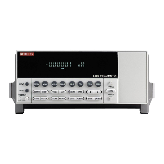
Page 9: Front Panel
When in Remote operation (REM annunciator lit), cancels GPIB remote mode. MENU Provides access to menu. POWER Power switch. In position turns 6485 on (I), out position turns it off (O). 2 Function keys MEDN Use to control and modify properties of the median filter. -
Page 10: Rear Panel Summary
Instrument addressed to talk over GPIB bus. TIMER Timer controlled triggering in use. TRIG External triggering (GPIB or trigger link) selected. 6 Handle Pull out and rotate to desired position. Rear panel summary The rear panel of Model 6485 is shown in Figure 1-2. -
Page 11: Rear Panel
1 INPUT This standard female BNC connector is used to connect the signal to be measured to the input of the Model 6485. Mates to a BNC cable. 2 CHASSIS This screw terminal is used to connect COMMON to CHASSIS ground via the ground link connector. -
Page 12: Analog Output
115V and 230VAC (nominal) at line frequencies of 50 or 60Hz automatically and over the bus. Changing line voltages requires changing fuses. Analog output The Model 6485 has an analog output on the rear panel. The ANALOG OUT provides a scaled, inverting ±2V output. A full-scale reading corresponds to ±2V output. WARNING The maximum safe voltage between picoammeter LO and chassis ground (common mode voltage) is 42V. - Page 13 Model 6485 Picoammeter Instruction Manual Getting Started 1-11 Figure 1-3 Typical analog output connections CAT I MADE IN U.S.A. IEEE-488 ANALOG OUT (CHANGE IEEE ADDRESS WITH FRONT PANEL MENU) INPUT TRIGGER LINK RS-232 LINE RATING 220V PK 50, 60Hz 30 VA...
-
Page 14: Line Power Connection
Section Power-up Line power connection Follow the procedure below to connect the Model 6485 to line power and turn on the instrument. Check to see that the line voltage indicated in the window of the fuse holder assem- (Figure 1-2) is correct for the operating voltage in your area. -
Page 15: Front Panel Procedure
Line frequency The Model 6485 operates at line frequencies of 50 or 60Hz. When auto detect is enabled (factory default), line frequencies are automatically sensed and set accordingly, therefore there are no switches to set. Use the :SYSTem:LFRequency? command (query) to read the line frequency. -
Page 16: Power-Up Sequence
Power-up sequence The following power-up sequence occurs when the Model 6485 is turned on: The Model 6485 performs self-tests on its EPROM and RAM with all digits and annunciators turned on. If a failure is detected, the instrument momentarily dis- plays an error message and the ERR annunciator turns on. -
Page 17: Default Settings
(FACT), three user-saved (USR0, USR1 and USR2), and bus default (GPIB). As shipped from the factory, Model 6485 powers up to the factory default settings. Factory default set- tings provide a general purpose setup for front panel operation, while the bus default (GPIB) settings do the same for remote operation. -
Page 18: Remote Setup Operation
Section Restoring factory or GPIB default setups The SYSTem:PRESet command returns Model 6485 to the factory defaults and the *RST command returns it to the GPIB defaults. The *RST command is documented in Section and SYSTem:PRESet is covered in... - Page 19 Model 6485 Picoammeter Instruction Manual Getting Started 1-17 Table 1-3 (continued) Default settings Factory GPIB Setting (:SYStem:PRESet) (*RST) GPIB: No effect (On at factory) Address No effect (14 at factory) Language No effect (SCPI at factory) Limit Tests: Limit 1 and Limit 2:...
-
Page 20: Scpi Programming
1-18 Getting Started Model 6485 Picoammeter Instruction Manual Menu Many aspects of operation are configured through the menus summarized in Table 1-4. Refer to the Section listed in the table in-depth information. To access the menu, press the MENU key. Use the range keys to scroll through the menu items, and the cursor keys to change options. -
Page 21: Optional Command Words
(?) that follows the command word. A query command requests (queries) the pro- grammed status of that command. When a query command is sent and Model 6485 is addressed to talk, the response message is sent to the computer. - Page 22 1-20 Getting Started Model 6485 Picoammeter Instruction Manual...
- Page 23 Measurement Concepts • Measurement overview — Explains the basic measurement capabilities of Model 6485. • Performance considerations — Covers a couple of considerations that affect overall performance; warm-up and autozero. • Connection fundamentals — Covers fundamental information about connecting test circuits to the picoammeter.
-
Page 24: Measurement Overview
Performance considerations Warm-up period Model 6485 can be used within one minute after it is turned on. However, the instrument should be turned on and allowed to warm up for at least one hour before use to achieve rated accuracy. If the instrument has been exposed to extreme temperatures, allow extra time for the internal temperature to stabilize. -
Page 25: Connection Fundamentals
' Query autozero. 1=on, 0=off Connection fundamentals The following provides important fundamental information on input connections to the Model 6485. Typical connection drawings are included with the various measurement pro- cedures provided in subsequent sections of this manual. Input connector... -
Page 26: Maximum Input Levels
Figure 2-2. WARNING The maximum safe voltage between picoammeter LO and chassis ground (common mode voltage) is 42V. The Model 6485 does not inter- nally limit the LO-to-chassis voltage. Exceeding 42V can create a shock hazard. CAUTION The LO-to-chassis breakdown voltage is 500V. Exceeding this voltage may cause damage to the instrument. -
Page 27: Low Noise Input Cables
When making precision measurements, you should always use low noise cables. The fol- lowing low noise cables are recommended for use with Model 6485: Model 4801 Input Cable — This 4 ft (1.2m) low-noise triax cable is terminated with male BNC connectors on each end. -
Page 28: Basic Connections To Dut
Model 6485. To prevent this damage, the following steps should be taken as a protection precau- tion. (An alternate protection method is described in “Measuring high resistance with... - Page 29 The 14MΩ in series will increase the measured resistance to 100.014GΩ The 6485 can be programmed to calculate the resistance and subtract the series resistance. Using the M/X+B function, in the example above, one would set M to 500, B to -14e6, and the units character to “omega”.
- Page 30 WARNING The maximum safe voltage between picoammeter LO and chassis ground (common mode voltage) is 42V. The Model 6485 does not inter- nally limit the LO-to-chassis voltage. Exceeding 42V can create a shock hazard.
-
Page 31: Input Voltage Overload (Ovrvolt Message)
(20µA to 20mA). Additionally, when operating on the 2mA and 20mA ranges or when the 6485 auto ranges up to these ranges as a response to the applied voltage, if the input voltage exceeds 60V, the Model 6485 will change from a current limit to a 1MΩ−... -
Page 32: Guard Plate
2-10 Measurement Concepts Model 6485 Picoammeter Instruction Manual Test fixture chassis • The chassis of the test fixture should be metal so that it can function as a shield for the DUT or test circuit. • The test box must have a lid that closes to prevent contact with live circuitry. -
Page 33: Input Protection
122° F (50° C) low-humidity environment for several hours. Input protection Model 6485 incorporates protection circuitry against nominal overload conditions. How- ever, a voltage higher than the maximum voltage value for the selected current range, and the resultant current surge could damage the input circuitry. -
Page 34: Floating Measurements
The maximum safe voltage between picoammeter LO and chassis ground (common mode voltage) is 42V. The Model 6485 does not inter- nally limit the LO-to-chassis voltage. Exceeding 42V can create a shock hazard. -
Page 35: Zero Check And Zero Correct
Model 6485 Picoammeter Instruction Manual Measurement Concepts 2-13 Figure 2-8 Floating measurements 6485 Picoammeter – Zero check and zero correct Table 2-3 lists the display messages associated with zero check and zero correct. The two-character message is displayed along with the reading. -
Page 36: Zero Correct
-Model 6485 will remain zero corrected even if it is upranged. If downranged, re-zero the instrument. -Model 6485 does not have to be re-zero corrected as long as the ambient tem- perature remains stable. -Zero correction cancels the voltage offset term of the amplifier. With both zero check and zero correct enabled, the instrument may not display a perfectly zeroed reading. -
Page 37: Scpi Programming - Zero Check And Zero Correct
Model 6485 Picoammeter Instruction Manual Measurement Concepts 2-15 SCPI programming — zero check and zero correct Table 2-4 SCPI commands — zero check and zero correct Commands Description Default SYSTem SYSTem Subsystem: :ZCHeck Zero check: [:STATe] <b> Enable or disable zero check. -
Page 38: Measurement Considerations
Input bias current Offset current of Model 6485 could affect low current measurements. Voltage burden Offset voltage of Model 6485 could cause errors if it is high in relation to the voltage of the measured circuit. Noise Noise generated by source resistance and source capacitance. - Page 39 Measurements • Measurement overview — Summarizes the current measurement capabilities of Model 6485 and provides a basic procedure to measure amps. • SCPI programming — Covers the basic SCPI commands.
- Page 40 Measurements Model 6485 Picoammeter Instruction Manual Measurement overview Measurements — Model 6485 can make amps measurements from 20fA to 21mA using 8 measurement ranges; 2nA, 20nA, 200nA, 2µA, 20µA, 200µA, 2mA, and 20mA. NOTE Accuracy specifications are provided in Appendix...
-
Page 41: Step 2. Perform Zero Correction
NOTE When not making floating measurements, it is recommended that you ground measurement LO at only one place in the circuit, such as with the ground link connection on the rear panel of the 6485. (See “Ground loops,” page C-2.) - Page 42 Measurements Model 6485 Picoammeter Instruction Manual Figure 3-1 Connections for amps Metal Noise Shield Metal Safety Input* Shield 4801, * 220V Peak 4802-10, or 4803 Safety Earth Ground CAT I MADE IN U.S.A. IEEE-488 ANALOG OUT (CHANGE IEEE ADDRESS WITH FRONT PANEL MENU)
Need help?
Do you have a question about the 6485 and is the answer not in the manual?
Questions and answers