Table of Contents
Advertisement
Quick Links
Model 6220 DC Current Source
Model 6221 AC and DC Current Source
Reference Manual
622X-901-01 Rev. B / June 2005
A
G R E A T E R
Test Equipment Depot - 800.517.8431 - 99 Washington Street Melrose, MA 02176 - TestEquipmentDepot.com
M E A S U R E
O F
C O N F I D E N C E
99 Washington Street
Melrose, MA 02176
Phone 781-665-1400
Toll Free 1-800-517-8431
Visit us at www.TestEquipmentDepot.com
Advertisement
Table of Contents

Related Manuals for Keithley 6220


Summary of Contents for Keithley 6220
- Page 1 Model 6220 DC Current Source Model 6221 AC and DC Current Source 99 Washington Street Reference Manual Melrose, MA 02176 622X-901-01 Rev. B / June 2005 Phone 781-665-1400 Toll Free 1-800-517-8431 Visit us at www.TestEquipmentDepot.com G R E A T E R...
- Page 2 WARRANTY Keithley Instruments, Inc. warrants this product to be free from defects in material and workmanship for a period of 1 year from date of shipment. Keithley Instruments, Inc. warrants the following items for 90 days from the date of shipment: probes, cables, rechargeable batteries, diskettes, and documentation.
- Page 3 Model 6220 DC Current Source Model 6221 AC and DC Current Source Reference Manual Test Equipment Depot - 800.517.8431 - 99 Washington Street Melrose, MA 02176 - TestEquipmentDepot.com...
- Page 4 Revision A (Document Number 622x-901-01) ..............June 2004 Revision B (Document Number 622x-901-01) ..............June 2005 All Keithley product names are trademarks or registered trademarks of Keithley Instruments, Inc. Other brand names are trademarks or registered trademarks of their respective holders.
- Page 5 Keithley products are designed for use with electrical signals that are rated Measurement Category I and Measurement Category II, as described in the International Electrotechnical Commission (IEC) Standard IEC 60664. Most measurement, control, and data I/O signals are Measurement Category I and must not be directly connected to mains voltage or to voltage sources with high transient over-voltages.
- Page 6 To maintain protection from electric shock and fire, replacement components in mains circuits, including the power transformer, test leads, and input jacks, must be purchased from Keithley Instruments. Standard fuses, with applicable national safety ap- provals, may be used if the rating and type are the same. Other components that are not safety related may be purchased from other suppliers as long as they are equivalent to the original component.
-
Page 7: Table Of Contents
Table of Contents Getting Started Introduction ......................Capabilities and features .................. Organization of manual sections ..............General information ....................Warranty information ..................Contact information ..................Safety symbols and terms ................Unpacking and inspection ................Options and accessories ................... User’s manual ....................Reference manual .................... - Page 8 Output Connections Output connectors ....................Triax connector ....................Ground points ....................LO and GUARD banana jacks ................ INTERLOCK ....................Output configurations ..................... Triax inner shield ..................... Triax output low ....................Guards ........................Guard overview ....................Triax Cable Guard ..................Banana Jack Guard ..................2-12 Floating the current source ...................
- Page 9 Delta, Pulse Delta, and Differential Conductance Part 1 ........................Overview ......................... Section overview ....................Operation overview ..................Test systems ......................Keithley instrumentation requirements ............System configurations ..................System connections ..................DUT test connections ..................Configuring communications ................. 5-10 Arming process ....................
- Page 10 Delta ........................5-20 Basic measurement process ................5-20 Model 622x measurement process ..............5-21 Configuration settings ................... 5-24 Arming process ..................... 5-24 Triggering sequence ..................5-25 Operation ....................... 5-27 Setup commands ................... 5-30 Pulse Delta ......................5-32 Model 6221 measurement process ..............5-32 Pulse Delta outputs ..................
- Page 11 Wave Functions (6221 Only) Overview ......................... Section overview ....................Wave function overview ................... Wave function characteristics .................. Setting waveform parameters ................Amplitude ......................Ranging ......................Frequency ......................Offset ........................ Duty cycle ......................Amplitude units ....................Phase marker ....................Duration ......................7-10 Arbitrary waveforms ..................
- Page 12 Input trigger requirements ................8-13 Output trigger specifications ................. 8-14 External trigger example ................8-15 Limit Test and Digital I/O Limit test ......................... Overview ......................Programming limit testing ................SCPI commands — limit testing ..............Digital I/O port ....................... Digital I/O connector ..................+5V output .......................
- Page 13 Status Structure Overview ....................... 11-2 Clearing registers and queues ................11-4 Programming and reading registers ..............11-5 Programming enable registers ................ 11-5 Reading registers .................... 11-6 Status byte and service request (SRQ) ..............11-7 Status byte register ..................11-7 Service request enable register ............... 11-8 Serial polling and SRQ ..................
- Page 14 Recommended test equipment ................16-4 Test equipment connections ................16-4 Calculating test limits ................... 16-4 Example limit calculation ................16-4 Restoring factory defaults ..................16-5 Test summary and considerations ................. 16-5 Test summary ....................16-5 Test considerations ..................16-5 Verification procedures ..................16-6 DC current output accuracy ................
- Page 15 IEEE-488 Bus Overview Introduction ......................Bus description ....................... Bus lines ......................... Data lines ......................Bus management lines ..................Handshake lines ....................Bus commands ....................... Uniline commands ..................Universal multiline commands ............... Addressed multiline commands ..............C-10 Address commands ..................C-10 Unaddress commands ...................
- Page 16 Test Equipment Depot - 800.517.8431 - 99 Washington Street Melrose, MA 02176 - TestEquipmentDepot.com...
-
Page 17: List Of Illustrations
Custom-built test fixture .................. 2-21 DC Current Source Operation Figure 3-1 Output boundaries (source and sink) ..............Figure 3-2 Source and compliance editing – Model 6220 ..........3-10 Figure 3-3 Source and compliance editing – Model 6221 ..........3-12 Sweeps Figure 4-1 Comparison of sweep types ................ - Page 18 Delta, Pulse Delta, and Differential Conductance Figure 5-1 Delta, Pulse Delta, and Differential Conductance measurements ...... Figure 5-2 System configurations for Delta, Pulse Delta, and Differential Conductance ... Figure 5-3 System connections – stand-alone operation ............. Figure 5-4 System connections – PC control of Model 622x ..........Figure 5-5 Guarded test connections .................
- Page 19 Figure 13-1 ASCII data format ..................... 13-5 Figure 13-2 IEEE-754 data formats ..................13-6 Figure 13-3 Model 6220 key-press codes ................13-10 Figure 13-4 Model 6221 key-press codes ................13-11 Performance Verification Figure 16-1 Connections for DC current output accuracy (200nA to 100mA ranges) ..
- Page 20 Calibration Figure 17-1 Connections for current source calibration (200nA to 100mA ranges) ... 17-8 Figure 17-2 Connections for current source calibration (2nA and 20nA ranges) ....17-9 Figure 17-3 Connections for compliance calibration ............17-11 Figure 17-4 Connections for guard calibration ..............17-12 IEEE-488 Bus Overview Figure C-1...
-
Page 21: List Of Tables
List of Tables Getting Started Table 1-1 Front panel default settings ................1-26 DC Current Source Operation Table 3-1 Source ranges and maximum outputs ..............Table 3-2 DC output commands ..................3-16 Sweeps Table 4-1 Logarithmic sweep points ................... Table 4-2 Sweep configuration menu ................ - Page 22 Limit Test and Digital I/O Table 9-1 Limit test commands ..................Table 9-2 Limit test fail pattern values ................Table 9-3 Digital I/O commands ..................Table 9-4 Digital I/O port values ..................9-10 Remote Operations Table 10-1 Communications menu ..................10-4 Table 10-2 Remote interface configuration commands ............
- Page 23 KI-220 Language Table 15-1 DDC emulation commands ................15-2 Performance Verification Table 16-1 Recommended test equipment ................16-4 Table 16-2 DC current output limits ................... 16-7 Calibration Table 17-1 Recommended calibration equipment .............. 17-4 Table 17-2 Calibration menu ....................17-6 Table 17-3 Front panel current calibration summary ............
- Page 24 Test Equipment Depot - 800.517.8431 - 99 Washington Street Melrose, MA 02176 - TestEquipmentDepot.com...
- Page 25 Getting Started Section 1 topics Introduction, page 1-2 Menus, page 1-18 Capabilities and features, page 1-2 CONFIG menus, page 1-18 Organization of manual sections, page 1-2 Direct access menus, page 1-19 General information, page 1-3 Editing controls, page 1-20 Warranty information, page 1-3 Source and compliance...
-
Page 26: Getting Started
Waveform functions (6221 only): sine, square, ramp and arbitrary function generator. • Five user-saved setups. • Delta testing when used with the Keithley Model 2182 or 2182A: • Delta – Uses a square wave output and a 3-point measurement algorithm to cancel the effects of thermal EMFs. •... -
Page 27: General Information
Contact information Worldwide phone numbers are listed at the front of this manual. If you have any questions, please contact your local Keithley representative or call one of our Application Engineers at 888-Keithley (534-8453) or 800-552-1115 (U.S. and Canada only). You can also contact Applications Engineering online at www.keithley.com. -
Page 28: Unpacking And Inspection
Getting Started Model 6220/6221 Reference Manual Unpacking and inspection Inspection for damage The Model 622x was carefully inspected electrically and mechanically before ship- ment. After unpacking all items from the shipping carton, check for any obvious signs of physical damage that may have occurred during transit. (There may be a protective film over the display lens, which can be removed.) Report any damage... -
Page 29: Options And Accessories
Model 6220/6221 Reference Manual Getting Started Options and accessories Input cables, connectors, and adapters 237-TRX-BAR Barrel Adapter – This is a barrel adapter that allows you to connect two triax cables together. Both ends of the adapter are terminated with 3-lug female triax connectors. - Page 30 Model 4288-2 side-by-side rack mount kit – Mounts two instruments (Models 182, 428, 486, 487, 2000, 2001, 2002, 2010, 2182, 2182A, 2400, 2410, 2420, 2430, 6220, 6221, 6430, 6485, 6487, 6517A, 7001) side-by-side in a standard 19-inch rack. Model 4288-4 side-by-side rack mount kit – Mounts Model 622x and a 5.25-inch instrument (Models 195A, 196, 220, 224, 230, 263, 595, 614, 617,...
-
Page 31: User's Manual
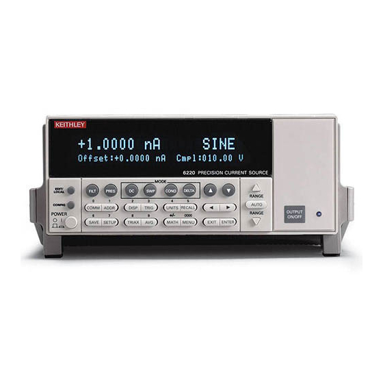
The rear panel of the Models 622x is shown in Figure 1-2. The Model 6221 rear panel is shown, but the Model 6220 is identical except it does not have the Ether- net connector. The descriptions of the rear panel components follow Figure 1-2. - Page 32 Getting Started Model 6220/6221 Reference Manual Figure 1-1 Models 6220 and 6621 front panels Model 6220: 6220 POWER Model 6221: 6221 POWER Return to Section 1 topics Test Equipment Depot - 800.517.8431 - 99 Washington Street Melrose, MA 02176 - TestEquipmentDepot.com...
- Page 33 Model 6220/6221 Reference Manual Getting Started 1 Special keys and power switch: EDIT/LOCAL Dual function – While in local, EDIT selects the source editing mode. While in remote, LOCAL cancel the remote mode. CONFIG Use to configure a function or operation.
- Page 34 1-10 Getting Started Model 6220/6221 Reference Manual Bottom Row SAVE Saves up to five instrument setups for future recall, and selects power-on setup. SETUP Restores a default setup (Preset or *RST) or a user saved setup. TRIAX Configures triax connector: inner shield and output Low. Can also press CONFIG >...
-
Page 35: Figure 1-2 Model 622X Rear Panel
Model 6220/6221 Reference Manual Getting Started 1-11 Figure 1-2 Model 622x rear panel NOTE 1 IEEE-488 Connector for IEEE-488 (GPIB) operation. Use a shielded cable, such as the Model 7006, 7007, or 7008. 2 OUTPUT 3-lug female triax connector for current source output. Mates to the supplied triax cable (237-ALG-2). -
Page 36: Heat Sink And Cooling Vents
1-12 Getting Started Model 6220/6221 Reference Manual 6 LO and GUARD Banana safety jacks for output low and banana jack Guard. 7 TRIGGER LINK Eight-pin micro-DIN connector for sending and receiving trigger pulses among connected instruments. Use a trigger link cable (Model 8501) for connections. - Page 37 Model 6220/6221 Reference Manual Getting Started 1-13 CAUTION To prevent damaging heat build-up, and thus ensure specified performance, adhere to the following precautions: • The heat sink must be kept free of dust, dirt and contami- nates, since its ability to dissipate heat could become impaired.
-
Page 38: Power-Up
1-14 Getting Started Model 6220/6221 Reference Manual Power-up CAUTION When handling the Model 622x, NEVER touch the heat sink located on the right side of the case. This heat sink could be hot enough to cause burns. Line power connection Follow the procedure below to connect the Model 622x to line power and turn on the instrument. -
Page 39: Power-Up Sequence
Appendix NOTE If a problem develops while the instrument is under warranty, return it to Keithley Instruments, Inc., for repair. Assuming no errors occur, the Model 622x will power-up as follows: • The message “INITIALIZING... “ is displayed for ~3 seconds. -
Page 40: Beeper And Keyclick
1-16 Getting Started Model 6220/6221 Reference Manual • The instrument model number, firmware revision levels, and the GPIB address are displayed briefly as follows: MODEL 622x Rev: xxx yyyy SCPI: 24 where: xxx is the main board ROM revision. yyyy is the display board ROM revision. -
Page 41: Source Preset
Model 6220/6221 Reference Manual Getting Started 1-17 Perform the following steps to control the beeper: Press MENU to display the MAIN MENU. Using the “Menu navigation” keys (see page 1-20), place the cursor on BEEPER and press ENTER. Place the cursor on DISABLE or ENABLE and press ENTER. Beeper enabled is the default setting. -
Page 42: Menus
1-18 Getting Started Model 6220/6221 Reference Manual Disabling the front panel provides the following benefits: • Allows testing on light sensitive devices. • Eliminates step-to-step timing jitter for Sweeps, Delta, and Differential Conductance. Details on “Step-to-step timing jitter” is provided on page 1-18. -
Page 43: Direct Access Menus
Model 6220/6221 Reference Manual Getting Started 1-19 Models 6220 and 6221: CONFIG > SWP opens CONFIGURE SWEEPS menu (Section 4). CONFIG > COND opens DIFF CONDUCTANCE menu (Section 5). CONFIG > DELTA opens CONFIGURE DELTA menu (Section 5). CONFIG > TRIG opens CONFIGURE TRIGGER menu (Section 8). -
Page 44: Editing Controls
1-20 Getting Started Model 6220/6221 Reference Manual After pressing the MAIN key, select TEST from the menu. The menu items are explained as follows: DISPLAY TESTS – The display tests include the following: • KEYS – Use to test front panel key operation. When a key is pressed, its label name will be displayed. -
Page 45: Figure 1-3 Menu Editing Keys
Model 6220/6221 Reference Manual Getting Started 1-21 Figure 1-3 Menu editing keys 6220 Editing Keys: 6221 Editing Keys: Cursor Keys Value Adjust Keys Rotary Knob & Cursor Keys Value Adjust Keys Numeric Entry Keys 0 1 2 3 4 5 6 7 8 9 +/– 0000 Numeric Entry Keys 0 1 2 3 4 5 6 7 8 9 +/–... -
Page 46: Password
Repeat step 2 as needed to set the desired value. Press ENTER to select the value. Pressing EXIT will cancel the change. Model 6221 menu navigation Editing for the Model 6221 is basically the same as editing for the Model 6220, except for the following differences: •... -
Page 47: Gpib And Language
Model 6220/6221 Reference Manual Getting Started 1-23 GPIB and language Press COMM to open the COMMUNICATIONS SETUP menu. Select the GPIB interface. NOTE If a different interface was being used, the Model 622x will reboot when GPIB is selected. If a reboot occurs, repeat steps 1 and 2, and then proceed to step 3. -
Page 48: Error And Status Messages
1-24 Getting Started Model 6220/6221 Reference Manual Error and status messages Error and status messages are displayed momentarily. During operation and programming, you will encounter a number of front panel messages. Typical messages are either of status or error variety, as listed in Appendix Messages, both status and error, are held in queues. -
Page 49: Remote Operation Setups
Model 6220/6221 Reference Manual Getting Started 1-25 To restore any setup Press SETUP to open the RESTORE SETUP menu: Select USER, PRESET, or *RST: • USER – Enter the desired value (0 to 4) and press ENTER. • PRESET – Press ENTER to return to the PRESET defaults. - Page 50 1-26 Getting Started Model 6220/6221 Reference Manual Selecting power-on setup The SYSTem:POSetup command is used to select which setup to return to on power-up. SYSTem:POSetup <name> ‘ Select power-on setup. <name> = RST, PRESet, SAV0, SAV1, SAV2, SAV3, or ‘...
- Page 51 Model 6220/6221 Reference Manual Getting Started 1-27 Table 1-1 (cont.) Front panel default settings PRESET and *RST Default Setting OUTPUT Fast Response (6221) Preset (PRES): 0.0mA, disabled Pulse Delta (PULSE): Unarmed I-Hi +1mA I-Low Width 0.110ms Count Infinite Ranging Best Src Del 0.016ms...
- Page 52 1-28 Getting Started Model 6220/6221 Reference Manual Table 1-1 (cont.) Front panel default settings PRESET and *RST Default Setting Trigger (TRIG) Arm Layer: Arm-In event Immediate Arm-Out menu: Line Events: Trig Layer Exit TL Enter Trig Layer: Immediate Trigger In...
-
Page 53: Scpi Programming
Model 6220/6221 Reference Manual Getting Started 1-29 SCPI programming SCPI programming information is integrated with front panel operation throughout this manual. SCPI commands are listed in tables and additional information that pertains exclusively to remote operation is provided after each table. - Page 54 1-30 Getting Started Model 6220/6221 Reference Manual Return to Section 1 topics Test Equipment Depot - 800.517.8431 - 99 Washington Street Melrose, MA 02176 - TestEquipmentDepot.com...
-
Page 55: Output Connections
Output Connections Section 2 topics Output connectors, page 2-2 Triax connector, page 2-2 Ground points, page 2-3 LO and GUARD banana jacks, page 2-3 INTERLOCK, page 2-4 Output configurations, page 2-5 Triax inner shield, page 2-7 Triax output low, page 2-7 Guards, page 2-8 Guard... -
Page 56: Output Connectors
Output Connections Model 6220/6221 Reference Manual Output connectors Triax connector Current source output is accessed at the 3-lug female triax connector on the rear panel. Use a 3-slot male triax cable to make connections to this connector. A triax cable terminated with alligator clips (Model 237-ALG-2) is supplied for the Model 622x (see “Supplied triax cable,”... -
Page 57: Ground Points
Model 6220/6221 Reference Manual Output Connections shield connection setting. See “Triax Cable Guard,” on page 2-9 for details on using the Cable Guard. Outer shield – The outer shield of the triax connector is always connected to Earth Ground of the Model 622x (see “Ground... -
Page 58: Interlock
Output Connections Model 6220/6221 Reference Manual GUARD banana jack The GUARD available at the banana jack is different from CABLE GUARD that can be accessed at the triax cable. See “Guards,” on page 2-8 for details on these two guards. -
Page 59: Output Configurations
Figure 2-5B). Using the Model 622x with the triax inner shield connected to Output Low makes it compatible with the Keithley Model 220 current source. WARNING To prevent electric shock and/or damage to the Model 622x, DO NOT exceed the maximum (Max) voltage levels indicated in... -
Page 60: Figure 2-4 Output Configurations - Triax Inner Shield Connected To Output Low
Output Connections Model 6220/6221 Reference Manual Figure 2-4 Output configurations – triax inner shield connected to Output Low A) Triax Output Low setting: Earth Ground B) Triax Output Low setting: Floating Output High Output High OUTPUT OUTPUT (red) (red) Output Low... -
Page 61: Triax Inner Shield
Triax inner shield The inner shield of the triax connector can be connected to Output Low (to be compatible with the Keithley Model 220 Current Source) or to Cable Guard. Output Low is the default connection. The current source OUTPUT must be OFF in order to change the inner shield set- ting. -
Page 62: Guards
Output Connections Model 6220/6221 Reference Manual Place the cursor on FLOATING or EARTH GROUND, and press the ENTER key. Press the EXIT key to return to the normal display state. Remote programming (triax output low) Commands for output low connection: ‘... -
Page 63: Triax Cable Guard
These capacitances, which cannot be guarded out, may negate the need for Cable Guard (especially for low-impedance DUT). The Keithley Model 2182/2182A Nanovoltmeter has rel- atively high input capacitance (~300pF, and ~500pF in special mode only). - Page 64 2-10 Output Connections Model 6220/6221 Reference Manual Leakage current – After capacitor C charges, it is effectively removed from the test circuit (assuming the source level remains constant). What is left is the 100GΩ insulator resistance (R ) in parallel with the 1GΩ DUT (R ), effectively making a current divider.
- Page 65 Model 6220/6221 Reference Manual Output Connections 2-11 Figure 2-7 Guarded triax cable – inner shield connected to Cable Guard (see Figure 2-5A) Ω Ω Ω Guarded DUT mounting plate There may be significant leakage and capacitance in the test fixture. A DUT is typ- ically mounted on a metal plate using insulated terminal posts.
-
Page 66: Banana Jack Guard
2-12 Output Connections Model 6220/6221 Reference Manual Figure 2-8 DUT mounting plate (unguarded and guarded) A) Unguarded circuit inner shield connected to Output Low B) Guarded circuit inner shield connected to Cable Guard Banana Jack Guard A typical test for the Model 622x is to source a current to a DUT and then use a voltmeter to measure the voltage across the DUT. -
Page 67: Floating The Current Source
For best accuracy, it is recommended that banana jack Guard be used. NOTE For the Keithley Model 2182/2182A Nanovoltmeter, the input impedance for the 100V range is 10MΩ. Therefore, for higher impedance DUT, voltage should be measured at banana jack Guard or Cable Guard. - Page 68 2-14 Output Connections Model 6220/6221 Reference Manual For the test circuit shown in Figure 2-10, the Model 622x current source must be configured to float off Earth Ground. As shown, Output Low of the Model 622x is floating +10V above Earth Ground. If Output Low of the Model 622x was instead connected to Earth Ground, the voltage source would be shorted through Earth Ground.
-
Page 69: Connections To Dut
Model 6220/6221 Reference Manual Output Connections 2-15 Connections to DUT WARNING To prevent electric shock, all power must be removed from the test system before making or breaking connections. Turn off all instruments and external sources, and disconnect their power cords. -
Page 70: Shields And Guarding
2-16 Output Connections Model 6220/6221 Reference Manual Figure 2-11 Basic connections to DUT A) Inner shield connected to Output Low B) Inner shield connected to Cable Guard Shields and guarding Noise shield connections Figure 2-12 shows typical noise shielding for the two triax connector configurations. -
Page 71: Figure 2-12 Noise Shield
Model 6220/6221 Reference Manual Output Connections 2-17 Figure 2-12 Noise shield A) Inner shield connected to Output Low B) Inner shield connected to Cable Guard, Output Low connected to Earth Ground Figure 2-13 Safety shield A) Inner shield connected to Output Low... - Page 72 2-18 Output Connections Model 6220/6221 Reference Manual Figure 2-14 Cable Guard connections – triax inner shield connected to Cable Guard Using shielding and guarding together Figure 2-15 shows connections for a test system that uses a noise shield, a safety shield, and guarding.
-
Page 73: Banana Jack Guard Connections
Model 6220/6221 Reference Manual Output Connections 2-19 Banana Jack Guard connections When using a low-impedance voltmeter to measure voltage, it may be necessary to make the measurement at banana jack Guard (see Figure 2-16). Keep in mind that banana jack Guard should only be used if voltmeter measurements at the DUT will result in significant loading errors. -
Page 74: Using A Test Fixture
Using a test fixture Custom-built test fixture A custom-built test fixture needs to a accommodate a variety of connection requirements, including connections to an external voltmeter (such as the Keithley Model 2182/2182A Nanovoltmeter). Figure 2-18 shows a test fixture that can be custom-built. The included connectors and terminals will accommodate any connection scheme covered in this section. -
Page 75: Figure 2-18 Custom-Built Test Fixture
Model 6220/6221 Reference Manual Output Connections 2-21 Figure 2-18 Custom-built test fixture Test fixture connections The following describes recommended connections for the test fixture shown in Figure 2-18. Note that the connectors for (B), (C), and (E) must be insulated from the metal chassis of the test fixture. - Page 76 2-22 Output Connections Model 6220/6221 Reference Manual (B) Three 5-way binding posts, or one 3-lug female triax connector – • If using the supplied triax cable (terminated with alligator clips), mount three 5-way binding points to the test fixture. •...
- Page 77 Model 6220/6221 Reference Manual Output Connections 2-23 Noise Shield or Guard plate A metal plate will provide noise shielding or guarding for the DUT or test circuit. It will also serve as a mounting panel for DUT or test circuits. The guard plate must be insulated with appropriate spacing from the chassis of the test fixture.
- Page 78 2-24 Output Connections Model 6220/6221 Reference Manual Return to Section 2 topics Test Equipment Depot - 800.517.8431 - 99 Washington Street Melrose, MA 02176 - TestEquipmentDepot.com...
- Page 79 DC Current Source Operation Section 3 topics Current source output capabilities, page 3-2 Source ranges, page 3-2 Compliance, page 3-3 Output power (source or sink), page 3-3 Output response, page 3-5 Setting source and compliance, page 3-9 Source and compliance editing, page 3-9 Sourcing...
-
Page 80: Dc Current Source Operation
DC Current Source Operation Model 6220/6221 Reference Manual Current source output capabilities • Nine ranges to source current from 100fA to 105mA. • Compliance can be set from 0.1V to 105V in 10mV steps. • Maximum output power is 11W. -
Page 81: Compliance
Model 6220/6221 Reference Manual DC Current Source Operation Compliance The compliance setting limits the output voltage of the Model 622x. The voltage compliance limit can be set from 0.1V to 105V in 10mV steps. The output will not exceed the programmed compliance level. - Page 82 DC Current Source Operation Model 6220/6221 Reference Manual When operating as a sink, the Model 622x is dissipating power rather than sourc- ing it. The polarity of the current and voltage seen at the output is opposite (one positive, one negative). An external source or an energy storage device, such as a capacitor, can force operation into the sink region.
-
Page 83: Output Response
6221 can be set to match the output response of the Model 6220 (both typically 100µs). For the Models 6220 and 6221, an analog filter can be enabled to slow down the output response. For a high-impedance load, the analog filter reduces overshoot, excessive noise, and instability (oscillation). - Page 84 The filter response speed of the Model 6221 can be set for FAST or SLOW. For the SLOW setting, the output response of the Model 6221 is the same as the out- put response of the Model 6220. Return to Section 3 topics Test Equipment Depot - 800.517.8431 - 99 Washington Street Melrose, MA 02176 - TestEquipmentDepot.com...
- Page 85 For the Model 6221, settling times are provided for the FAST and SLOW response speed settings. Note that the SLOW setting of the Model 6221 has the same response as the Model 6220. Enabling the analog filter may or may not significantly increase settling times. For details, see “Analog filter,”...
- Page 86 Rl is the load resistance in ohms. Vpp is the peak-to-peak voltage step (100V < Vpp < 210V). 200nA, 20nA, and 2nA ranges (Models 6220 and 6221) The step response for these ranges is largely determined by the impedance of the load, which is primarily made up of the load resistance and parasitic load capaci- tance.
-
Page 87: Setting Source And Compliance
3-14. Source and compliance editing Figure 3-3 shows how to set source and compliance values for the Model 6220. Figure 3-4 shows the source and compliance editing controls for the Model 6221. The procedure to set source and compliance values for the Model 6221 follow Figure 3-4. - Page 88 3-10 DC Current Source Operation Model 6220/6221 Reference Manual Figure 3-3 Source and compliance editing – Model 6220 Step 3 Enter editing mode Step 1 Step 2 Select source range Select DC output mode Value Adjust Key Cursor Key Step 4 Set source or compliance value...
- Page 89 The unit will exit the editing mode if an editing action is not performed within six seconds. To re-enter the edit mode, do one of the following. • For the Model 6220, press a Value Adjust Key or a Cursor Key to re- enter the edit mode for the last selected field. •...
- Page 90 3-12 DC Current Source Operation Model 6220/6221 Reference Manual Figure 3-4 Source and compliance editing – Model 6221 DC Output Rotary Knob & Cursor Keys Range Keys Select Key EDIT key Numeric Entry Keys 0 1 2 3 4 5 6 7 8 9 +/– 0000...
-
Page 91: Autorange
Model 6220/6221 Reference Manual DC Current Source Operation 3-13 Autorange Front panel operation The AUTO range key is a single action control to select the best fixed range for the displayed source value. After setting a source value, pressing AUTO will ensure that the best fixed range is selected. -
Page 92: Sourcing Current
3-14 DC Current Source Operation Model 6220/6221 Reference Manual When finished using the preset value, press PRES again to disable the feature. The “PRES” message will cancel, and the unit will return to the original source value. Note that the compliance value cannot be preset. - Page 93 (3). If desired, change the output response For the Models 6220 and 6221, an analog output filter can be enabled to slow down the output response. For the Model 6221, the output response can be set to FAST or SLOW. See “Output response,”...
-
Page 94: Remote Programming - Source Output Commands
3-16 DC Current Source Operation Model 6220/6221 Reference Manual (4). Turn on the output NOTE In order to turn on the output, an interlock switch must be connected to the INTERLOCK connector on the rear panel of the Model 622x. Closing the in- terlock switch will enable the OUTPUT allowing it to be turned on. -
Page 95: Table 3-2 Dc Output Commands
Model 6220/6221 Reference Manual DC Current Source Operation 3-17 Table 3-2 DC output commands Command Description Default Turns output off and sets output level to zero. CLEar 1, 2 Sets current source range (amps). 100e-3 CURRent:RANGe <n> <n> = -105e-3 to 105e-3 Enables or disables source autorange. - Page 96 3-18 DC Current Source Operation Model 6220/6221 Reference Manual Return to Section 3 topics Test Equipment Depot - 800.517.8431 - 99 Washington Street Melrose, MA 02176 - TestEquipmentDepot.com...
-
Page 97: Sweeps
Sweeps Section 4 topics Overview, page 4-2 Remote sweep operation, page 4-14 Section overview, page 4-2 Running a linear staircase sweep, page 4-15 Sweep overview, page 4-2 Running a log staircase sweep, page 4-16 Running a custom sweep, page 4-17 Sweep characteristics, page 4-4... -
Page 98: Overview
Sweeps Model 6220/6221 Reference Manual Overview Section overview Following a brief “Sweep overview” of the three types of sweeps (linear staircase, logarithmic staircase, and custom), the documentation in this section provides detailed information on characteristics, front panel operation, and SCPI command programming for each type of sweep as follows: •... - Page 99 Model 6220/6221 Reference Manual Sweeps Figure 4-1 Comparison of sweep types 5mA (Stop) Start Bias A. Linear Staircase Sweep Stop 100mA 10mA Logarithmic scale shown for staircase steps. 0.1mA Start Bias B. Logarithmic Staircase Sweep Last Point First Point Bias C.
-
Page 100: Sweep Characteristics
Sweeps Model 6220/6221 Reference Manual Sweep characteristics NOTE Jitter – Step-to-step sweep timing may jitter as much as 1ms. This jitter can be eliminated by disabling the front panel. For details, see “Step-to-step timing jitter,” on page 1-18. Linear staircase sweeps... -
Page 101: Logarithmic Staircase Sweeps
Model 6220/6221 Reference Manual Sweeps Logarithmic staircase sweeps This sweep is similar to the linear staircase sweep. The steps, however, are done on a logarithmic scale as shown in the example sweep in Figure 4-3. This exam- ple is a 5-point log sweep from 1mA to 10mA. The sweep delay parameter deter- mines the time period for each step. -
Page 102: Custom Sweeps
Sweeps Model 6220/6221 Reference Manual The programmable parameters for a log sweep include the start and stop current levels, the number of measurement points for the sweep, and the sweep delay. The specified start, stop, and point parameters determine the logarithmic step size for the sweep. - Page 103 Model 6220/6221 Reference Manual Sweeps Figure 4-4 shows an example of a custom sweep over the range of 1mA to 10mA with arbitrary steps. When the sweep is triggered, the current goes from the bias level to the first point in the sweep. The unit cycles through the sweep points in the programmed order.
-
Page 104: Setting Sweep Parameters
Sweeps Model 6220/6221 Reference Manual Setting sweep parameters Custom sweep editing A typical custom sweep editing display is shown below: P12345: +1.234567 mA Del:123456.789s Cmpl:100.00 V The leftmost value on the top line is the point number, and the next value is the actual current setting. - Page 105 Model 6220/6221 Reference Manual Sweeps Source ranging The source ranging setting determines how the Model 622x selects the current range based on the sweep steps as follows: • BEST — With this option, the unit will select a single fixed source range that will accommodate all of the source levels in the sweep.
-
Page 106: Front Panel Sweep Operation
4-10 Sweeps Model 6220/6221 Reference Manual Front panel sweep operation NOTE User setups cannot be saved or recalled while a sweep is armed or running. Attempting to do so will generate error +413 Not allowed with mode armed. Using the sweep configuration menu... -
Page 107: Performing A Linear Staircase Sweep
Model 6220/6221 Reference Manual Sweeps 4-11 Performing a linear staircase sweep Configure source functions: If desired, set the bias current (output current prior to the start of the sweep) by pressing the DC key and then setting the current to the desired value. -
Page 108: Performing A Log Staircase Sweep
4-12 Sweeps Model 6220/6221 Reference Manual Performing a log staircase sweep Configure source functions: If desired, set the bias current (output current prior to the start of the sweep) by pressing the DC key and then setting the current to the desired value. -
Page 109: Performing A Custom Sweep
Model 6220/6221 Reference Manual Sweeps 4-13 Performing a custom sweep Configure the bias current (output current prior to the start of the sweep) by pressing the DC key and then setting the current to the desired value. Configure the sweep as follows: Press CONFIG then SWP to enter the sweep configuration menu. -
Page 110: Remote Sweep Operation
4-14 Sweeps Model 6220/6221 Reference Manual Remote sweep operation Procedures for programming and running a sweep for each of the three sweep types are given on the following pages. Each of these procedures includes commands for a typical sweep example. -
Page 111: Running A Linear Staircase Sweep
Model 6220/6221 Reference Manual Sweeps 4-15 Running a linear staircase sweep Configure source functions. Examples – The following commands restore defaults, set the bias current to 100μA, and the compliance to 10V: ‘ Restore 622x defaults. *RST ‘ Set bias current to 100μA SOUR:CURR 1e-4 ‘... -
Page 112: Running A Log Staircase Sweep
4-16 Sweeps Model 6220/6221 Reference Manual Running a log staircase sweep Configure source functions. Examples – The following commands restore defaults, set the bias current to 10μA, and the compliance to 5V: ‘ Restore 622x defaults. *RST ‘ Set bias current to 10μA SOUR:CURR 1e-5 ‘... -
Page 113: Running A Custom Sweep
Model 6220/6221 Reference Manual Sweeps 4-17 Running a custom sweep Configure source functions. Examples – The following commands restore defaults and set the bias current to 50μA: ‘ Restore 622x defaults. *RST ‘ Set bias current to 50μA SOUR:CURR 5e-5 Configure the sweep. -
Page 114: Scpi Commands - Sweeps
4-18 Sweeps Model 6220/6221 Reference Manual SCPI commands — sweeps Commands for linear and logarithmic staircase sweeps are listed in Table 4-4, while commands for custom (list) sweeps are listed in Table 4-5, page 4-21. Addi- tional information for each command is provided in notes that follow the tables. - Page 115 Model 6220/6221 Reference Manual Sweeps 4-19 1. SOUR:CURR:STAR<n> ‘ Set start current SOUR:CURR:STOP <n> ‘ Set stop current SOUR:CURR:STEP <n> ‘ Set step current Use these commands to set the start and stop currents for linear and logarithmic staircase sweeps and to set the step current for linear staircase sweeps. Setting the stop value more positive than the start value will result in a positive-going sweep.
- Page 116 4-20 Sweeps Model 6220/6221 Reference Manual 1.0E-13, and Error +420 Log sweep zero adjusted will be issued. Note that start or stop values are not restored back to zero if the SPACing is subse- quently changed back to LINear, so make sure the start and stop values are correct after sending the SOUR:SPACing command.
- Page 117 Model 6220/6221 Reference Manual Sweeps 4-21 Table 4-5 Custom (list) sweep commands Command Description Defines list of currents. SOURce[1]:LIST:CURRent <NRf> <NRf> = -0.105 to 0.105 (A) [,<NRf>, ...<NRf>] Adds current points to existing list. SOURce[1]:LIST:CURRent:APPend <NRf> <NRf> = -0.105 to 0.105 (A) [,<NRf>, ...<NRf>]...
-
Page 118: Coupled Sweep Commands
4-22 Sweeps Model 6220/6221 Reference Manual 4. SOUR:LIST:CURR:POIN? ‘ Query current list length SOUR:LIST:DEL:POIN? ‘ Query delay list length SOUR:LIST:COMP:POIN? ‘ Query compliance list These commands query the length of the current source, delay, and compli- ance lists. The number of current values determines the length of the list sweep;... -
Page 119: Sweep Status Model Events
Model 6220/6221 Reference Manual Sweeps 4-23 Sweep status model events Three status model events are available for monitoring sweep progress, all of which set bits in the Operation Condition Register (see Section 11 for complete details on the status model). - Page 120 4-24 Sweeps Model 6220/6221 Reference Manual Return to Section 4 topics Test Equipment Depot - 800.517.8431 - 99 Washington Street Melrose, MA 02176 - TestEquipmentDepot.com...
-
Page 121: Delta, Pulse Delta, And Differential Conductance
5-2 Model 622x measurement process, page 5-21 Configuration settings, page 5-24 Test systems, page 5-4 Arming process, page 5-24 Keithley instrumentation requirements, page 5-4 Triggering sequence, page 5-25 System configurations, page 5-4 Operation, page 5-27 System connections, page 5-6... -
Page 122: Overview
5-20) provide the details for each delta test. Operation overview The Model 6220 or 6221 Current Source can be used with a Model 2182/2182A Nanovoltmeter to perform Delta and Differential Conductance. The Model 6221/ 2182A combination can also perform Pulse Delta. These operations use a delta current-reversal technique to cancel the effects of thermal EMFs. - Page 123 Model 6220/6221 Reference Manual Delta, Pulse Delta, and Differential Conductance Figure 5-1 Delta, Pulse Delta, and Differential Conductance measurements A) Delta measurements DELTA DELTA Reading Reading DELTA DELTA Reading Reading B) Pulse Delta measurements Pulse Delta Pulse Delta Pulse Delta...
-
Page 124: Test Systems
Keithley instrumentation requirements Keithley instrumentation requirements for Delta, Pulse Delta, and Differential Conductance: • Models 6220 and 2182 – Delta and Differential Conductance • Models 6220 and 2182A – Delta and Differential Conductance • Models 6221 and 2182 – Delta and Differential Conductance •... - Page 125 Figure 5-2 System configurations for Delta, Pulse Delta, and Differential Conductance A) Stand-alone system (front panel operation) B) PC control of 6220/21 Return to Section 5 topics Test Equipment Depot - 800.517.8431 - 99 Washington Street Melrose, MA 02176 - TestEquipmentDepot.com...
-
Page 126: System Connections
Delta, Pulse Delta, and Differential Conductance Model 6220/6221 Reference Manual System connections WARNING Before making or breaking system connections, the Models 622x and 2182/2182A, and the PC must be turned off and the line cords must be disconnected from AC line power. - Page 127 IEEE-488 or Ethernet (6221) – This system configuration uses a PC to communi- cate with the Model 622x. For the Model 6220, the IEEE-488 bus interface can be used. For the Model 6221, the IEEE-488 bus or the Ethernet can be used. For the Ethernet, make sure to use a cross-over Ethernet cable for direct connection to the PC.
-
Page 128: Dut Test Connections
Delta, Pulse Delta, and Differential Conductance Model 6220/6221 Reference Manual Figure 5-4 System connections – PC control of Model 622x DUT test connections WARNING Before making or breaking test connections, the Models 622x and 2182/2182A must be turned off and the line cords must be disconnected from AC line power. - Page 129 Model 6220/6221 Reference Manual Delta, Pulse Delta, and Differential Conductance Inner shield connection for OUTPUT NOTE By default, the inner shield of the OUTPUT connec- tor of the Model 622x is connected to output low. For details on the inner shield connections for the...
-
Page 130: Configuring Communications
5-10 Delta, Pulse Delta, and Differential Conductance Model 6220/6221 Reference Manual Figure 5-5 Guarded test connections NOTE For this connection scheme, the inner shield of the Model 622x OUTPUT connector must be connected to the driven guard. See “Guarding,” on page 5-8... -
Page 131: Arming Process
Model 6220/6221 Reference Manual Delta, Pulse Delta, and Differential Conductance 5-11 Model 622x communications For Delta, Pulse Delta, and Differential Conductance, the Model 622x uses two interfaces for communications. It uses the RS-232 to communicate with the Model 2182/2182A, and it uses the GPIB or Ethernet (Model 6221 only) to communicate with the PC. - Page 132 5-12 Delta, Pulse Delta, and Differential Conductance Model 6220/6221 Reference Manual Communications test and setup commands • If a sweep or delta test is already running, sending an arm command causes error -221 Settings Conflict. • The Model 622x performs communication tests with the Model 2182/2182A.
-
Page 133: Interlock
Model 6220/6221 Reference Manual Delta, Pulse Delta, and Differential Conductance 5-13 Aborting the delta test A delta test that is armed (or running) can be aborted by pressing the EXIT key or sending the SOUR:SWE:ABOR command. Interlock In order to start an armed Delta, Pulse Delta, or Differential Conductance test, a test fixture interlock switch must be connected to the INTERLOCK connector on the rear panel of the Model 622x. - Page 134 5-14 Delta, Pulse Delta, and Differential Conductance Model 6220/6221 Reference Manual NOTE The SMPL annunciator blinks on and off for every other reading that is acquired from the Model 2182/2182A. The blinking annunciator indicates that communications with the Model 2182/2182A are working properly. That is, the Model 2182/2182A is performing voltage measurements and successfully sending them to the Model 622x.
-
Page 135: Read Commands
Model 6220/6221 Reference Manual Delta, Pulse Delta, and Differential Conductance 5-15 Read commands Figure 5-6B also shows the read commands that can be used for remote programming. A Pre-math readings SENSe[1]:DATA[:LATest]? SENSe[1]:DATA:FRESh? While Delta, Pulse Delta, or Differential Conductance is running, the SENS:DATA:LATest? command can be sent to read the latest (last) pre-math reading processed by the Model 622x. -
Page 136: Measurement Units
5-16 Delta, Pulse Delta, and Differential Conductance Model 6220/6221 Reference Manual D Buffer readings TRACe:DATA? TRACe:DATA:TYPE? TRACe:DATA:SELected? <start>, <count> CALCulate2:DATA? With readings stored in the buffer, use TRACe:DATA? to return all readings. Use TRACe:DATA:TYPE? to determine the type of readings stored in the buffer (returns NONE, DELT, DCON, or PULS). -
Page 137: Setting Measurement Units
Model 6220/6221 Reference Manual Delta, Pulse Delta, and Differential Conductance 5-17 Setting measurement units From the front panel, units can be set as follows: Press the UNITS key to display the READING UNITS menu. Use the Menu navigation controls (see... -
Page 138: Error And Status Messages
5-18 Delta, Pulse Delta, and Differential Conductance Model 6220/6221 Reference Manual When recalling buffer statistics (such as Average or Standard Deviation) for Pulse Delta power readings, only the power units for the first stored reading is checked to determine if it is a Peak or Average power reading. The result of the buffer statistic will have the same units (W for Average, or Wp for Peak) as the first stored reading. - Page 139 Model 6220/6221 Reference Manual Delta, Pulse Delta, and Differential Conductance 5-19 Table 5-2 (cont.) Error/status codes and messages +411 Diff. Conductance step Occurs if two adjacent Diff Reduce the number of steps by Conductance values use the same increasing the step size or widen error source value.
-
Page 140: Delta
= 200µV / 2 = 100µV The Keithley Models 2182 and 2182/2182A can perform fundamental Delta mea- surements using a conventional bipolar current source. For details on the funda- mental Delta process, see “Delta” in Section 5 of the Model 2182/2182A User’s Manual. -
Page 141: Model 622X Measurement Process
Model 6220/6221 Reference Manual Delta, Pulse Delta, and Differential Conductance 5-21 NOTE The previous discussion on the fundamental Delta pro- cess is provided as background information to summarize delta measurements using a conventional bipolar current source. The following information refers to an enhanced Delta op- eration using the Model 622x with a Model 2182/2182A. - Page 142 5-22 Delta, Pulse Delta, and Differential Conductance Model 6220/6221 Reference Manual Figure 5-7 Delta measurement technique DELTA DELTA Reading Reading DELTA DELTA Reading Reading 〈 〈 1st Delta Reading 3rd Delta Reading 〈 〈 2nd Delta Reading 4th Delta Reading The following equation can be used to calculate any Delta reading: ⎛...
- Page 143 Model 6220/6221 Reference Manual Delta, Pulse Delta, and Differential Conductance 5-23 The (-1) term in the Delta calculation is used for polarity reversal of every other calculated Delta reading. This makes all calculated Delta readings in the test the same polarity.
-
Page 144: Configuration Settings
5-24 Delta, Pulse Delta, and Differential Conductance Model 6220/6221 Reference Manual Configuration settings Delta settings from the front panel are described as follows. These parameters are set from the CONFIGURE DELTA menu that is accessed by pressing the CONFIG key and then the DELTA key. -
Page 145: Triggering Sequence
Model 6220/6221 Reference Manual Delta, Pulse Delta, and Differential Conductance 5-25 Communications, setup commands, and sweep table • The Model 622x performs a communications test and sends setup com- mands to the Model 2182/2182A. These operations are explained in “Com- munications test and setup commands,”... - Page 146 5-26 Delta, Pulse Delta, and Differential Conductance Model 6220/6221 Reference Manual • Model 2182/2182A – After its Trigger Delay expires, the Model 2182/2182A performs another measurement conversion (A/D #2). An output trigger pulse is then sent back to the Model 622x.
-
Page 147: Operation
Model 6220/6221 Reference Manual Delta, Pulse Delta, and Differential Conductance 5-27 Operation NOTE Delta readings from the Model 2182/2182A will be unfiltered. Noisy Delta readings can be fil- tered by the Model 622x before sending them into the buffer. See Section 6 for details. - Page 148 5-28 Delta, Pulse Delta, and Differential Conductance Model 6220/6221 Reference Manual If a finite Delta count is being used, the Delta measurements will stop after the last Delta measurement is performed. However, Delta remains armed and can be run again by pressing the TRIG key. The new Delta readings will overwrite the old readings in the buffer.
- Page 149 Model 6220/6221 Reference Manual Delta, Pulse Delta, and Differential Conductance 5-29 Examples – The following commands demonstrate proper syntax for sending commands and returning responses to queries over the serial port: ‘ Select 2V range for 2182/ SYST:COMM:SER:SEND “VOLT:RANG 2”...
-
Page 150: Setup Commands
5-30 Delta, Pulse Delta, and Differential Conductance Model 6220/6221 Reference Manual Read Delta readings – While Delta is running, the latest Model 2182/ 2182A Delta reading can be read by the Model 622x using the following command: SENS:DATA? ‘ Reads the latest Delta reading. -
Page 151: Table 5-3 Delta Commands
Model 6220/6221 Reference Manual Delta, Pulse Delta, and Differential Conductance 5-31 Table 5-3 Delta commands Command Description Default [SOURce[1]]:DELTa:NVPResent? Queries connection to 2182A. 1 = yes, 0 = no [SOURce[1]]:DELTa:HIGH <NRf> Sets high source value (amps). 1e-3 <NRf> = 0 to 105e-3 Sets low source value (amps). -
Page 152: Pulse Delta
Delta, Pulse Delta, and Differential Conductance Model 6220/6221 Reference Manual Pulse Delta Use the Keithley Model 2182A with the Model 6221 to run Pulse Delta. Model 6221 measurement process Pulse Delta measurements For Pulse Delta, the Model 6221 outputs current pulses. Current pulses that have a short pulse width are ideal to test a low-power DUT that is heat sensitive. - Page 153 Model 6220/6221 Reference Manual Delta, Pulse Delta, and Differential Conductance 5-33 In cases where the high pulse will cause heating of the DUT, the measurement at the second low pulse could be adversely affected by the heat caused by the high pulse.
- Page 154 5-34 Delta, Pulse Delta, and Differential Conductance Model 6220/6221 Reference Manual The affects of heating can be eliminated by not performing the measurement at point C (low pulse). For this 2-point measurement technique, Pulse Delta is calcu- lated as follows: ⎛...
-
Page 155: Pulse Delta Outputs
Model 6220/6221 Reference Manual Delta, Pulse Delta, and Differential Conductance 5-35 Average power is then calculated as follows: W (average power) = I x V x Duty Cycle Example – Assume the following for Pulse Delta: • Pulse Delta voltage is 5V •... -
Page 156: Figure 5-10 Pulse Timing
5-36 Delta, Pulse Delta, and Differential Conductance Model 6220/6221 Reference Manual Fixed output Figure 5-10 shows one Pulse Delta cycle for a Fixed output. As shown, the Model 6221 outputs a low pulse, a high pulse, and then another low pulse during every Pulse Delta cycle. - Page 157 Model 6220/6221 Reference Manual Delta, Pulse Delta, and Differential Conductance 5-37 Sweep output The sweep feature of the Model 6221 can be used to output a series of pulses that allow the use of different levels for the high pulses. Each high pulse returns to the programmed low pulse level.
- Page 158 5-38 Delta, Pulse Delta, and Differential Conductance Model 6220/6221 Reference Manual Figure 5-11 Pulse sweep output examples A) Staircase sweep pulse train: 2 to 10mA in 2mA steps B) Logarithmic sweep pulse train: 1 to 10mA using 5 logarithmic C) Custom sweep pulse train: 1mA, 2mA, 4mA, 8mA, and 16mA (5 points)
-
Page 159: Configuration Settings
Model 6220/6221 Reference Manual Delta, Pulse Delta, and Differential Conductance 5-39 Duty cycle Duty cycle defines the ratio between pulse “on” time and pulse “off” time during a Pulse Delta cycle. For example, for a 25% duty cycle, the pulse would be “on”... - Page 160 5-40 Delta, Pulse Delta, and Differential Conductance Model 6220/6221 Reference Manual Fixed output settings These following parameters are set from the CONFIG PULSE DELTA menu that is accessed by pressing the CONFIG key and then the PULSE key. I-Hi and I-Lo These settings specify the high and low level of the pulses.
- Page 161 Model 6220/6221 Reference Manual Delta, Pulse Delta, and Differential Conductance 5-41 Interval The Pulse Delta cycle time period (interval) is expressed as a number of power line cycles (PLC). For 60Hz, one PLC is 16.667ms, and for 50Hz, one PLC is 20ms.
-
Page 162: Arming Process
5-42 Delta, Pulse Delta, and Differential Conductance Model 6220/6221 Reference Manual Arming process After Pulse Delta (Fixed output or Sweep output) is configured, the test is armed by pressing the PULSE key or sending SOUR:PDEL:ARM. During the arming pro- cess, the Model 6221 establishes communications with the Model 2182A and per- forms a series of operations. -
Page 163: Triggering Sequence
Model 6220/6221 Reference Manual Delta, Pulse Delta, and Differential Conductance 5-43 Triggering sequence The Trigger Link is used to synchronize source-measure triggering operations of the Models 6221 and 2182A. See “System connections,” on page 5-6 for details on Trigger Link connections. -
Page 164: Operation
5-44 Delta, Pulse Delta, and Differential Conductance Model 6220/6221 Reference Manual Figure 5-12 Pulse Delta triggering sequence (two lows measured) 2182A A/D #2 2182A A/D #3 Pulse Delta 2182A A/D #1 Reading Operation NOTE Pulse Delta readings from the Model 2182A will be unfiltered. - Page 165 Model 6220/6221 Reference Manual Delta, Pulse Delta, and Differential Conductance 5-45 Perform one the following steps to configure Pulse Delta: Step I for Fixed output, or step II for Sweep output. “Configuration settings” are explained page 5-39. Fixed output – On the Model 6221, press CONFIG and then PULSE to access the CONFIG PULSE DELTA menu.
- Page 166 5-46 Delta, Pulse Delta, and Differential Conductance Model 6220/6221 Reference Manual If a finite Pulse Delta count is being used, the Pulse Delta measurements will stop after the last Pulse Delta measurement is performed. However, Pulse Delta remains armed and can be run again by pressing the TRIG key.
- Page 167 Model 6220/6221 Reference Manual Delta, Pulse Delta, and Differential Conductance 5-47 Set measurement units – Volts are the default units for the Model 6221 but can instead be expressed (and displayed) as an Ohms, Watts, or Sie- mens reading (see “Measurement units,”...
- Page 168 5-48 Delta, Pulse Delta, and Differential Conductance Model 6220/6221 Reference Manual The previous read command reads the last Pulse Delta reading that was performed by the Model 2182A. If this command is sent before a new reading is available, the last Pulse Delta reading will again be returned.
-
Page 169: Setup Commands
Model 6220/6221 Reference Manual Delta, Pulse Delta, and Differential Conductance 5-49 Setup commands Pulse Delta setup and arm commands Commands sent from the PC to the Model 6221 to set up and arm Pulse Delta are listed in Table 5-4. - Page 170 5-50 Delta, Pulse Delta, and Differential Conductance Model 6220/6221 Reference Manual 1. Use the :NVPResent command to determine if a suitable Model 2182A with the correct firmware revision is properly connected to the RS-232 port. This query command can be used for the system configuration shown in...
-
Page 171: Differential Conductance
Model 6220/6221 Reference Manual Delta, Pulse Delta, and Differential Conductance 5-51 Differential Conductance Differential measurements can be used to study the individual slopes of an I-V (or V-I) curve. By applying a known differential current (dI) to a device, differential volt- age (dV) measurements can be performed. -
Page 172: Figure 5-14 Differential Conductance Measurement Process
5-52 Delta, Pulse Delta, and Differential Conductance Model 6220/6221 Reference Manual Figure 5-14 Differential Conductance measurement process dV Calc dV Calc dV Calc dV Calc dV Calc dV Calc dV Calculations · · · · · · dG and dR Calculations... - Page 173 Model 6220/6221 Reference Manual Delta, Pulse Delta, and Differential Conductance 5-53 Differential Conductance calculations dV calculations While the dV calculations for the first six dV readings are shown in Figure 5-14, the following formula can be used to calculate any dV reading in the test: –...
- Page 174 5-54 Delta, Pulse Delta, and Differential Conductance Model 6220/6221 Reference Manual Measurement units The fundamental measurement for Differential Conductance is differential voltage (dV). However, the dV reading can be converted into a differential conductance (dG), differential resistance (dR) or power (Watts) reading. See...
-
Page 175: Configuration Settings
Model 6220/6221 Reference Manual Delta, Pulse Delta, and Differential Conductance 5-55 Average Current is calculated by the Model 622x as follows: ------------------ - ------------------ AvgCurr -------------------------------------------- - AvgCurr --------------------------- - Where: AvgCurr is the Average Current corresponding to a given Differential Conductance reading. -
Page 176: Arming Process
5-56 Delta, Pulse Delta, and Differential Conductance Model 6220/6221 Reference Manual formed at each stepped delta level. Delta is a magnitude and is therefore always set as a positive value. Delta can be set from 0 to 105mA. The default Delta set- ting is 1µA. - Page 177 Model 6220/6221 Reference Manual Delta, Pulse Delta, and Differential Conductance 5-57 Differential Conductance step size – When using the repeating filter with Differ- ential Conductance, the actual step size run for the test is the programmed step size divided by the filter count: Step Size (repeating filter) = Programmed Step Size / Filter Count For example, assume the programmed step size is 10µA and the Filter Count is...
-
Page 178: Triggering Sequence
5-58 Delta, Pulse Delta, and Differential Conductance Model 6220/6221 Reference Manual The following error aborts the arming process: • Error +416 Step size too small NOTE Table 5-2 explains these coded error and status messages. This table also provides remedies for the errors. -
Page 179: Operation
Model 6220/6221 Reference Manual Delta, Pulse Delta, and Differential Conductance 5-59 • Model 2182/2182A – After its Trigger Delay expires, the Model 2182/2182A performs another measurement conversion (A/D Rdg #3). The differential voltage (dV) is then calculated by the Model 622x. The Model 2182/2182A outputs trigger pulse back to the Model 622x to output the next stepped cur- rent level. - Page 180 5-60 Delta, Pulse Delta, and Differential Conductance Model 6220/6221 Reference Manual Connections are shown in the following illustrations. All power must be removed from all components in the system before making connections: • Figure 5-3, page 5-7 – System connections •...
- Page 181 Model 6220/6221 Reference Manual Delta, Pulse Delta, and Differential Conductance 5-61 Operation – PC control The system configuration for PC control of the Model 622x is shown in Figure 5-2B. Connections are shown in the following illustrations. All power must be removed from all components in the system before making connections: •...
- Page 182 5-62 Delta, Pulse Delta, and Differential Conductance Model 6220/6221 Reference Manual Set measurement units – Volts are the default units for the Model 622x but can instead be expressed (and displayed) as an Ohms, Watts, or Siemens reading (see “Measurement units,” on page 5-16 for details).
- Page 183 Model 6220/6221 Reference Manual Delta, Pulse Delta, and Differential Conductance 5-63 NOTE If a read command is sent when Differential Con- ductance is not running, error -221 Settings Con- flict will occur. See Table 5-2 for details on errors associated with Differential Conductance opera- tion.
-
Page 184: Setup Commands
5-64 Delta, Pulse Delta, and Differential Conductance Model 6220/6221 Reference Manual Setup commands Setup and arm commands Commands sent from the PC to the Model 622x to set up and arm Differential Conductance are listed in Table 5-3. Additional information for each command are provided in notes that follow the table. - Page 185 Model 6220/6221 Reference Manual Delta, Pulse Delta, and Differential Conductance 5-65 3. After setting up Differential Conductance using the above setup commands, the :ARM command arms Differential Conductance. During the arming pro- cess, the Model 622x communicates with the Model 2182/2182A. Details on “Arming...
- Page 186 5-66 Delta, Pulse Delta, and Differential Conductance Model 6220/6221 Reference Manual Return to Section 5 topics Test Equipment Depot - 800.517.8431 - 99 Washington Street Melrose, MA 02176 - TestEquipmentDepot.com...
-
Page 187: Averaging Filter, Math, And Buffer
Averaging Filter, Math, and Buffer Section 6 topics Averaging filter, page 6-2 Averaging filter characteristics, page 6-2 Filter setup and control, page 6-8 Remote programming – Averaging filter, page 6-8 Math, page 6-11 mX+b and m/X+b (reciprocal), page 6-9 Configuring and controlling mX+b and m/X+b, page 6-9 Remote programming –... -
Page 188: Averaging Filter
Averaging Filter, Math, and Buffer Model 6220/6221 Reference Manual Averaging filter The average filter can be used with Delta, Pulse Delta, and Differential Conduc- tance. There are two types of averaging filter: moving and repeating. “Filter type” is explained on page 6-3. - Page 189 Model 6220/6221 Reference Manual Averaging Filter, Math, and Buffer Filter type There are two averaging filter types: moving and repeating. These filter types are shown in Figure 6-1. Moving filter Basic moving filter operation – For the moving filter, every delta reading yields a filtered Delta reading.
- Page 190 Averaging Filter, Math, and Buffer Model 6220/6221 Reference Manual With the filter settled, the storage of filtered Delta readings begin. The next 25 Delta cycles yields 25 filtered readings, which are stored in the buffer. After the 25 Delta reading is stored in the buffer, the Delta test stops.
- Page 191 Model 6220/6221 Reference Manual Averaging Filter, Math, and Buffer Figure 6-1 Digital filter types: moving and repeating A) Moving filter (count = 10) B) Repeating filter (count = 10) Filter window The averaging filter uses a “noise” window to control filter threshold. As long as the signal remains within the selected window, A/D conversions continue to be placed in the stack.
- Page 192 Averaging Filter, Math, and Buffer Model 6220/6221 Reference Manual The noise window for the two filter types are compared in Figure 6-2. For the filters using the Filter Window (1%), it also shows a window violation occurring after the sixth A/D conversion. When the voltage makes the transition from Voltage A to Voltage B, the window violation causes the “A”...
-
Page 193: Figure 6-2 Filter Window
Model 6220/6221 Reference Manual Averaging Filter, Math, and Buffer Figure 6-2 Filter window Return to Section 6 topics Test Equipment Depot - 800.517.8431 - 99 Washington Street Melrose, MA 02176 - TestEquipmentDepot.com... -
Page 194: Filter Setup And Control
Averaging Filter, Math, and Buffer Model 6220/6221 Reference Manual Filter setup and control When the averaging filter is enabled, the FILT annunciator turns on and bit B8 (Filter Settled) of the Operation Event Register resets to 0 (see Section 11 details on status structure). -
Page 195: Math
Model 6220/6221 Reference Manual Averaging Filter, Math, and Buffer Math mX+b and m/X+b (reciprocal) These math functions affect the results of the Delta, Pulse Delta, or Differential Conductance operations. Details on the delta operations are covered in Section mX+b and m/X+b manipulate delta readings (X) from the model mathematically... -
Page 196: Remote Programming - Math
6-10 Averaging Filter, Math, and Buffer Model 6220/6221 Reference Manual Remote programming – Math Commands for mX+b and m/X+b math calculations are listed in Table 6-3. Table 6-3 Math commands Command Description Default Select math format. CALCulate[1]:FORMat <name> <name> = NONE, MXB or RECiprocal Set “m”... -
Page 197: Buffer
Model 6220/6221 Reference Manual Averaging Filter, Math, and Buffer 6-11 Programming example — mX+b This command sequence performs a single mX+b calculation and displays the result on the computer CRT. Note that Delta, Pulse Delta, or Differential Conduc- tance must be running when the CALC1 read command is sent. -
Page 198: Buffer Characteristics
6-12 Averaging Filter, Math, and Buffer Model 6220/6221 Reference Manual Buffer characteristics Buffer size The buffer size automatically sets to accommodate the number delta readings to be performed. For example, if the test is configured to perform 1,000 delta mea- surements, the buffer size will be set to 1000. - Page 199 Model 6220/6221 Reference Manual Averaging Filter, Math, and Buffer 6-13 • Mean is the mean average of the buffer readings. Mean is calculated as follows: ∑ ---- - Where: is a stored reading. n is the number of stored readings.
-
Page 200: Storing Readings
6-14 Averaging Filter, Math, and Buffer Model 6220/6221 Reference Manual Storing readings For front panel operation, the buffer is always active (enabled), and post-math readings are automatically stored in the buffer. For remote programming, buffer feed can be pre-math readings or post-math readings, or the buffer can be disabled. -
Page 201: Remote Programming - Buffer
Model 6220/6221 Reference Manual Averaging Filter, Math, and Buffer 6-15 Figure 6-3 Buffer recall A) Front panel edit keys to display buffer readings: B) Use EDIT/LOCAL key to display buffer statistics: EDIT/ ® ® ® ® ® LOCAL For remote programming, the commands to recall delta readings and statistics... -
Page 202: Table 6-4 Buffer Commands
6-16 Averaging Filter, Math, and Buffer Model 6220/6221 Reference Manual Table 6-4 Buffer commands Command Description Default Clear readings from buffer. Note 1 TRACe:CLEar Query memory bytes available in buffer. TRACe:FREE? Specify buffer size (number of readings to store). Note 2 TRACe:POINts <n>... - Page 203 Model 6220/6221 Reference Manual Averaging Filter, Math, and Buffer 6-17 1. TRACe:NOTify <NRf> <NRf> = 1 to (TRAC:POIN -1) Use this command to specify the number of stored readings that will set bit B6 (Trace Notify) of the Measurement Event Register. With Service Request Enable Register properly configured, an SRQ will be generated when the specified Trace Notify value is exceeded.
- Page 204 6-18 Averaging Filter, Math, and Buffer Model 6220/6221 Reference Manual TRACe:DATA:SELected? <start>, <count> – With this read command, you can specify a list of consecutive buffer readings to return. Two parameters are required for this command: <start> and <count>. The first reading in the buffer is Rdg #0.
- Page 205 Wave Functions (6221 Only) Section 7 topics Overview, page 7-2 Remote wave function operation, page 7-21 Section overview, page 7-2 Programming sine waves, page 7-22 Wave function overview, page 7-2 Programming square waves, page 7-23 Programming ramp waveforms, page 7-24 Wave function characteristics, page 7-3...
-
Page 206: Wave Functions (6221 Only)
Wave Functions (6221 Only) Model 6220/6221 Reference Manual Overview Section overview Following a brief “Wave function overview” for the four types of waveforms (sine, square wave, ramp, and arbitrary), the documentation in this section provides detailed information on characteristics, front panel operation, and SCPI command programming for each type of wave function as follows: •... -
Page 207: Wave Function Characteristics
Model 6220/6221 Reference Manual Wave Functions (6221 Only) Wave function characteristics Table 7-1 summarizes the basic characteristics of the four wave functions avail- able in the Model 6221. More details on various aspects can be found in the fol- lowing paragraphs. -
Page 208: Setting Waveform Parameters
Wave Functions (6221 Only) Model 6220/6221 Reference Manual Setting waveform parameters Editing parameters The AMPL and FREQ keys also function as left arrow and right arrow keys, respectively, when editing a numeric value or scrolling through menu. Examples: • Press FREQ while editing the 1’s digit on 001000.000 Hz line. Press FREQ again while the 0 is flashing, and the cursor moves to the 0.1 place. -
Page 209: Amplitude
Model 6220/6221 Reference Manual Wave Functions (6221 Only) Amplitude The amplitude setting range for all four waveform types is from 1pA to 105mA peak. The peak-to-peak value is double the amplitude setting. For example, a 1mA amplitude setting results in a 2mA peak-to-peak waveform. -
Page 210: Frequency
Wave Functions (6221 Only) Model 6220/6221 Reference Manual Example 3 Ranging: BEST Amplitude: 20mA peak Offset: 0.2mA ARB values: range from +0.1 to -0.1 These settings will generate a waveform with a peak-to-peak value of 4mA on the 20mA range. Note that this waveform with no offset would use the 2mA range but uses the 20mA range since the range is set based on the amplitude and offset values. -
Page 211: Duty Cycle
Model 6220/6221 Reference Manual Wave Functions (6221 Only) Figure 7-1 Offset example 10mA Peak 20mA p-p Duty cycle For a square wave (Figure 7-2A), the duty cycle setting is the portion of the total cycle that the wave is high relative to the period of the waveform. For a ramp... -
Page 212: Figure 7-2 Duty Cycle
Wave Functions (6221 Only) Model 6220/6221 Reference Manual Figure 7-2 Duty cycle A. Square Wave Duty Cycle B. Ramp Wave Duty Cycle Return to Section 7 topics Test Equipment Depot - 800.517.8431 - 99 Washington Street Melrose, MA 02176 - TestEquipmentDepot.com... -
Page 213: Phase Marker
Model 6220/6221 Reference Manual Wave Functions (6221 Only) Phase marker The phase marker (Figure 7-3) allows you to set a pulse marker that defines a specific point of a waveform over a range of 0 to 360°. The phase marker signal is a 1μs pulse that appears on the selected line of the external trigger connector... -
Page 214: Duration
7-10 Wave Functions (6221 Only) Model 6220/6221 Reference Manual Duration The duration setting defines how long the waveform is generated. You can set the duration in time over a range of 100ns to 999999.999s, in cycles from 0.001 to 99999999900 cycles (provided the equivalent time, cycles/frequency does not exceed the upper time duration limit), or choose a continuous waveform (INFinite setting). -
Page 215: Figure 7-4 Waveform Triggering
Model 6220/6221 Reference Manual Wave Functions (6221 Only) 7-11 Figure 7-4 Waveform triggering Output Waveform Waveform Starts Within 1μs of Trigger Pulse Leading Edge High Trigger Link Input Pulse (See Section 8 for Details) Front panel external trigger control External trigger selections are included with the waveform configuration menu... - Page 216 7-12 Wave Functions (6221 Only) Model 6220/6221 Reference Manual Controlling waveform retriggering behavior By default, the waveform will restart immediately upon each sequential external hardware trigger in this mode. If the waveform output has not yet run to comple- tion, a new hardware trigger will preempt the current waveform and restart the...
- Page 217 Model 6220/6221 Reference Manual Wave Functions (6221 Only) 7-13 Figure 7-5 Waveform retriggering Output Waveform Trigger Accepted Waveform Aborts and Restarts Trigger Pulses A. Waveform Aborts in Restart Mode (Default) Output Waveform Trigger Ignored Waveform Completes Trigger Pulses B. Waveform Completes in Ignore Mode...
-
Page 218: Front Panel Wave Function Operation
7-14 Wave Functions (6221 Only) Model 6220/6221 Reference Manual Front panel wave function operation NOTE User setups cannot be saved or recalled while wave is armed or running. Attempting to do so will generate error +413 Not allowed with mode armed. - Page 219 Model 6220/6221 Reference Manual Wave Functions (6221 Only) 7-15 Table 7-2 Wave function configuration menu Menu selection Description TYPE Select waveform type: SINE Select sine wave. SQUARE Select square wave. RAMP Select ramp wave. ARBx Select user-defined arbitrary wave. * Where: x = 0 to 4.
-
Page 220: Generating A Sine Wave
7-16 Wave Functions (6221 Only) Model 6220/6221 Reference Manual Generating a sine wave If you intend to use fixed ranging, manually set the range high enough to accommodate both the amplitude and offset setting. Configure the waveform as follows: Press CONFIG then WAVE to enter the wave function configuration menu. -
Page 221: Generating A Square Wave
Model 6220/6221 Reference Manual Wave Functions (6221 Only) 7-17 Generating a square wave If you intend to use fixed ranging, manually set the range high enough to accommodate both the amplitude and offset setting. Configure the waveform as follows: Press CONFIG then WAVE to enter the wave function configuration menu. -
Page 222: Generating A Ramp Waveform
7-18 Wave Functions (6221 Only) Model 6220/6221 Reference Manual Generating a ramp waveform If you intend to use fixed ranging, manually set the range high enough to accommodate both the amplitude and offset setting. Configure the waveform as follows: Press CONFIG then WAVE to enter the wave function configuration menu. -
Page 223: Generating An Arbitrary Waveform
Model 6220/6221 Reference Manual Wave Functions (6221 Only) 7-19 Generating an arbitrary waveform NOTE Arbitrary waveforms cannot be defined from the front panel, but they can be generated once defined by using the general procedure below. If you are using the fixed range setting, manually set the range to a high enough setting to accommodate the expected amplitude and offset set- tings. -
Page 224: Using The External Trigger Mode
7-20 Wave Functions (6221 Only) Model 6220/6221 Reference Manual Using the external trigger mode Set up the desired waveform operation using the previous procedures. Enable the external trigger mode: Press CONFIG then WAVE to enter the wave function configuration menu. -
Page 225: Remote Wave Function Operation
Model 6220/6221 Reference Manual Wave Functions (6221 Only) 7-21 Remote wave function operation Procedures for programming and generating waveforms for each of the four wave- form types are given on the following pages. Each of these procedures includes commands for a typical wave function example. -
Page 226: Programming Sine Waves
7-22 Wave Functions (6221 Only) Model 6220/6221 Reference Manual Programming sine waves Restore defaults with this command: *RST Configure the waveform. Examples – The following commands configure 1kHz sine wave with an amplitude of 10mA, 1mA offset, and phase marker off: ‘... -
Page 227: Programming Square Waves
Model 6220/6221 Reference Manual Wave Functions (6221 Only) 7-23 Programming square waves Restore defaults with this command: *RST Configure the waveform. Examples – The following commands configure a 10kHz square wave with an amplitude of 1mA, 0mA offset, 50% duty cycle, 180° phase marker, and 10 second duration: ‘... -
Page 228: Programming Ramp Waveforms
7-24 Wave Functions (6221 Only) Model 6220/6221 Reference Manual Programming ramp waveforms Restore defaults with this command: *RST Configure the waveform. Examples – The following commands configure a 50kHz ramp wave with an amplitude of 5mA, 0mA offset, 25% duty cycle, 90° phase marker, and 15 second duration: ‘... -
Page 229: Programming Arbitrary Waveforms
Model 6220/6221 Reference Manual Wave Functions (6221 Only) 7-25 Programming arbitrary waveforms Restore defaults with this command: *RST Configure the waveform. Examples – The following commands configure 100kHz arbitrary wave with an amplitude of 25mA, 0mA offset, phase marker off, and 20 second duration: ‘... -
Page 230: Programming An Externally Triggered Waveform
7-26 Wave Functions (6221 Only) Model 6220/6221 Reference Manual Programming an externally triggered waveform Restore defaults with this command: *RST Configure the desired waveform using one of the procedures previously described for a sine, square, ramp, or arbitrary waveform. Configure the low jitter external trigger mode. -
Page 231: Scpi Commands - Wave Functions
Model 6220/6221 Reference Manual Wave Functions (6221 Only) 7-27 SCPI commands — wave functions Commands for wave functions are listed in Table 7-4. Additional information for each command is provided in notes that follow the tables. Table 7-4 Waveform function commands... - Page 232 7-28 Wave Functions (6221 Only) Model 6220/6221 Reference Manual Table 7-4 (cont.) Waveform function commands Command Description Default Arms 6221 for waveform output. SOURce[1]:WAVE:ARM Starts waveform output. SOURce[1]:WAVE:INITiate Aborts waveform output. SOURce[1]:WAVE:ABORt Sets waveform time duration. INFinity SOURce[1]:WAVE:DURation:TIME <NRf> <NRf> = 100e-9 to 999999.999 (s) or INFinity Sets waveform duration in cycles.
- Page 233 Model 6220/6221 Reference Manual Wave Functions (6221 Only) 7-29 2. SOUR:WAVE:DCYC <NRf> ‘ Set duty cycle This command sets the duty cycle for square and ramp waveforms. For a square wave, the duty cycle is the portion of the total cycle that the wave is high.
- Page 234 7-30 Wave Functions (6221 Only) Model 6220/6221 Reference Manual 8. SOUR:WAVE:ARB:DATA <NRf>[,NRf,...NRf] ‘ Define arbitrary points This command creates the points list for the arbitrary waveform. The data must be in the range -1 to 1. The maximum number of points allowed in this command is 100;...
- Page 235 Model 6220/6221 Reference Manual Wave Functions (6221 Only) 7-31 15. SOUR:WAVE:DUR:TIME <NRf> ‘ Set duration of waveform in time This command sets the time duration in seconds that the waveform will run after being started with the INIT command. The default setting is INFinity sec- onds, and valid choices range from 100e-9 seconds to 999999.999 seconds,...
- Page 236 7-32 Wave Functions (6221 Only) Model 6220/6221 Reference Manual 19. SOUR:WAVE:EXTR:IGN <b> ‘ Set retrigger behavior When this command is disabled (OFF), the waveform will restart immediately upon each sequential external hardware trigger. If the waveform output has not yet run to completion, a new hardware trigger will preempt the current waveform and restart the waveform immediately.
- Page 237 Triggering Section 8 topics Trigger models, page 8-2 Front panel trigger model, page 8-2 Trigger model operation, page 8-3 Trigger model operation, page 8-4 Front panel trigger operation, page 8-7 Using the trigger configuration menu, page 8-7 Configuring triggering, page 8-8 Remote trigger operation, page 8-9...
-
Page 238: Triggering
Triggering Model 6220/6221 Reference Manual Trigger models The trigger models control when to switch to the next point in a sweep and how many sweeps to perform (see Section 4 for details on sweeps). Note that the trig- ger configuration does not affect other Model 622x operation including normal out- put currents and Model 6221 wave functions. -
Page 239: Remote Trigger Model
Model 6220/6221 Reference Manual Triggering Remote trigger model The trigger model for remote operation is shown in Figure 8-2. Figure 8-2 Trigger model for remote operation Idle Layer Trigger Layer Return to Section 8 topics Test Equipment Depot - 800.517.8431 - 99 Washington Street Melrose, MA 02176 - TestEquipmentDepot.com... -
Page 240: Trigger Model Operation
Triggering Model 6220/6221 Reference Manual Trigger model operation Idle and initiate While in the idle state, the instrument cannot perform sweeps. Once the Model 622x is taken out of idle, operation proceeds through the trigger model to perform sweeps and sweep steps. - Page 241 Model 6220/6221 Reference Manual Triggering Event detectors and control sources A control source holds up operation until the programmed event occurs and is detected. Note that there are four detector bypasses (two of which are one-time bypasses). A bypass around a detector is only enabled if the appropriate TLink control source is selected.
- Page 242 Triggering Model 6220/6221 Reference Manual Trigger-In source — The Trigger-In control sources, which control individual sweep steps, are explained as follow: • IMMEDIATE (TRIGger:SOURce IMMediate) — Event detection for the trig- ger layer is satisfied immediately allowing operation to continue to perform a sweep step.
-
Page 243: Front Panel Trigger Operation
Model 6220/6221 Reference Manual Triggering Output triggers The Model 622x can send out an output trigger (via the rear panel TRIGGER LINK connector) right after the source and delay phase of the device action and/or when operation enters or exits the trigger layer. An output trigger can be used to trigger another instrument to perform an operation (e.g., select the next scanner channel). -
Page 244: Configuring Triggering
Triggering Model 6220/6221 Reference Manual Configuring triggering The following is a typical example of using trigger configuration to fine-tune sweeps. For further details on the steps for sweep configuration, see “Front panel sweep operation,” on page 4-10. When setting trigger model parameters, keep the following in mind: •... -
Page 245: Remote Trigger Operation
Model 6220/6221 Reference Manual Triggering Remote trigger operation The following is a typical example of using remote trigger configuration to enhance sweeps. For further details on the steps for sweep programming, see “Remote sweep operation,” on page 4-14. When setting trigger model parameters, keep the following in mind: •... -
Page 246: Scpi Commands - Triggering
8-10 Triggering Model 6220/6221 Reference Manual SCPI commands — triggering Triggering commands are listed in Table 8-2. Additional information for each com- mand is provided in notes that follow the tables. Table 8-2 Trigger commands Command* Description Default Initiate one trigger cycle. - Page 247 Model 6220/6221 Reference Manual Triggering 8-11 1. INIT ‘ Initiate one trigger cycle This command is used to initiate one trigger cycle and take the unit out of the idle state. 2. ABOR ‘ Reset trigger system This command resets the trigger system. If a sweep is in progress, it will be halted and the source value set to zero.
- Page 248 8-12 Triggering Model 6220/6221 Reference Manual 12. TRIG:DIR <name> ‘ Set TRIG source bypass. This command enables (SOURce) or disables (ACCeptor) the TRIG source bypass. 13. TRIG:ILIN <NRf> ‘ Set TRIG layer TRIG input line. This command selects the TRIG layer input signal line: 1, 2, 3, 4, 5, or 6.
-
Page 249: External Triggering
Model 6220/6221 Reference Manual Triggering 8-13 External triggering External trigger connector Input and output triggers are received and sent via the rear panel TRIGGER LINK connector. The trigger link has six lines. At the factory, line #2 is selected for out- put triggers and line #1 is selected for input triggers. -
Page 250: Output Trigger Specifications
8-14 Triggering Model 6220/6221 Reference Manual Figure 8-5 Trigger link input pulse specifications μ Output trigger specifications The Model 622x can be programmed to output a trigger immediately after the source or delay phase of the device action and/or when operation enters or exits the trigger layer of the trigger model. -
Page 251: External Trigger Example
Model 6220/6221 Reference Manual Triggering 8-15 External trigger example In a simple test system, you may want to close a switching channel and source the current to a DUT connected to that channel. Using sweeps, the current to each DUT can be set to a different value. Such a test system is shown in Figure 8-7. - Page 252 8-16 Triggering Model 6220/6221 Reference Manual For this example, the Model 622x and switching mainframe are configured as follows: Model 622x Switching Mainframe Factory Defaults Restored Factory Defaults Restored Trig-In Event = TLink Scan List = 1!1-1!10 Trigger Input Line = #2...
- Page 253 Model 6220/6221 Reference Manual Triggering 8-17 Operation of the Model 622x starts at point A in the flowchart where it waits for an external trigger. Pressing STEP takes Model 7001/7002 out of idle and places operation at point B in the flowchart.
- Page 254 8-18 Triggering Model 6220/6221 Reference Manual Return to Section 8 topics Test Equipment Depot - 800.517.8431 - 99 Washington Street Melrose, MA 02176 - TestEquipmentDepot.com...
- Page 255 Limit Test and Digital I/O Section 9 topics Limit test, page 9-2 Overview, page 9-2 Programming limit testing, page 9-2 SCPI commands — limit testing, page 9-3 Digital I/O port, page 9-5 Digital I/O connector, page 9-5 output, page 9-5 line, page 9-6 Simplified...
-
Page 256: Limit Test
Limit Test and Digital I/O Model 6220/6221 Reference Manual Limit test Overview As shown in Figure 9-1, there is one limit test that can be performed on a DUT. Limit 1 is used to test whether or not the Model 622x current source is in or out of compliance. -
Page 257: Scpi Commands - Limit Testing
Model 6220/6221 Reference Manual Limit Test and Digital I/O SCPI commands — limit testing Limit test commands are listed in Table 9-3. Additional information for each com- mand is provided in notes that follow the tables. Table 9-1 Limit test commands... - Page 258 Limit Test and Digital I/O Model 6220/6221 Reference Manual Table 9-2 Limit test fail pattern values Value* Out 4 Out 3 Out 2 Out 1 *L = Grounded H ≥ +3V Return to Section 9 topics Test Equipment Depot - 800.517.8431 - 99 Washington Street Melrose, MA 02176 - TestEquipmentDepot.com...
-
Page 259: Digital I/O Port
Model 6220/6221 Reference Manual Limit Test and Digital I/O Digital I/O port Digital I/O connector The Model 622x Digital I/O port is a male DB-9 connector located on the rear panel. The port location and pin designations are shown in Figure 9-2. -
Page 260: Sot Line
Limit Test and Digital I/O Model 6220/6221 Reference Manual SOT line The SOT (start-of-test) line provides an alternate method of triggering the unit. You can set up the unit to trigger on a positive-going, negative-going, or a both positive and negative-going pulse. See triggering in Section 8 for complete details. - Page 261 Model 6220/6221 Reference Manual Limit Test and Digital I/O CAUTION Do not exceed +33V maximum voltage on pin 5 of the digital I/O port and do not use any output line to sink >500mA. Exceeding these limits may cause damage to the instrument that is not covered by the warranty.
-
Page 262: Source Mode - Logic Control
Limit Test and Digital I/O Model 6220/6221 Reference Manual Source mode — logic control The digital outputs can be used as logic inputs to active TTL, low-power TTL, or CMOS inputs. For this mode of operation, the output lines can source up to ~5mA. -
Page 263: Scpi Commands - Force Digital I/O Pattern
Model 6220/6221 Reference Manual Limit Test and Digital I/O For example, send these commands to force a digital I/O pattern of 0101 (5) by remote: ‘ Enable I/O pattern force. CALC3:FORC:STAT ON ‘ Set I/O to 5 (0101) CALC3:FORC:PATT 5 SCPI commands —... - Page 264 9-10 Limit Test and Digital I/O Model 6220/6221 Reference Manual Table 9-4 Digital I/O port values Value* Out 4 Out 3 Out 2 Out 1 *L = Grounded H ≥ +3V Return to Section 9 topics Test Equipment Depot - 800.517.8431 - 99 Washington Street Melrose, MA 02176 - TestEquipmentDepot.com...
- Page 265 Remote Operations Section 10 topics Selecting and configuring an interface, page 10-2 RS-232 interface reference, page 10-25 Interfaces, page 10-2 Sending and receiving data, page 10-24 Languages, page 10-3 RS-232 settings, page 10-25 Interface selection and configuration, page 10-3 RS-232 connections, page 10-27 Programming...
-
Page 266: Remote Operations
10-2 Remote Operations Model 6220/6221 Reference Manual Selecting and configuring an interface Interfaces The Model 6220 supports two built-in remote interfaces: • GPIB interface • RS-232 interface The Model 6221 supports three built-in remote interfaces: • GPIB interface • RS-232 interface •... -
Page 267: Languages
GPIB, RS-232, and Ethernet interfaces. DDC language — The Model 622x implements most DDCs (device-dependent commands) available in the Keithley Model 220 current source. The available commands are provided in Section 15. See the Model 220 Instruction Manual for details on operation. -
Page 268: Table 10-1 Communications Menu
Select whether to clear communications password. Do not clear password. Clear password. 1. The Ethernet interface is not available on the Model 6220. 2. The MAC address is displayed only and cannot be changed by the user. Typical decimal notation address shown. - Page 269 Model 6220/6221 Reference Manual Remote Operations 10-5 Configuring the RS-232 interface Press the COMM key, select RS-232, and press ENTER. If you are changing to the RS-232 interface from a different interface, the Model 622x will perform a power-on reset, and you must re-enter the COMM menu.
- Page 270 10-6 Remote Operations Model 6220/6221 Reference Manual “Ethernet interface reference,” on page 10-29 for more information on the Ethernet interface. NOTE When the IP address, the Ethernet gateway, or subnet mask is changed, the unit will perform a power-on reset when leaving the menu.
-
Page 271: Table 10-2 Remote Interface Configuration Commands
Model 6220/6221 Reference Manual Remote Operations 10-7 Table 10-2 Remote interface configuration commands Command Description Selects remote interface. SYSTem:COMMunicate:SELect <name> <name> = SERial, GPIB, or ETHernet. GPIB interface command: Sets GPIB primary address. SYSTem:COMMunicate:GPIB:ADDRess <NRf> <NRf> = 0 to 30, default 12. - Page 272 10-8 Remote Operations Model 6220/6221 Reference Manual Table 10-2 (cont.) Remote interface configuration commands Command Description Ethernet interface commands (6221 only): SYSTem:COMMunicate:ETHernet:ADDRess <string> Sets IP address of 6221. <string> = “n.n.n.n” Sets subnet mask of 6221. SYSTem:COMMunicate:ETHernet:MASK <string> <string> = “n.n.n.n”...
- Page 273 Model 6220/6221 Reference Manual Remote Operations 10-9 3. SYST:COMM:SER:CONT:RTS <name> ‘ Select hardware handshaking. This command enables (IBFull or RFR) or disables (OFF) hardware hand- shaking. 4. SYST:COMM:SER:PACE <name> ‘ Set flow control. This command sets software flow control; XON to enable or OFF (default) to disable.
- Page 274 10-10 Remote Operations Model 6220/6221 Reference Manual 12. SYST:COMM:ETH:GAT <string> ‘ Set Ethernet gateway. This command sets the Ethernet gateway of the Model 6221. The gateway parameter is of the form “n.n.n.n”, where each n is a decimal representation of a single byte with a value of 0 to 255.
- Page 275 Model 6220/6221 Reference Manual Remote Operations 10-11 19. SYST:PASS:STAT? ‘ Query state of password. This query requests the state of password protection. “0” will be returned if password protected commands are disabled; “1” will be returned if the pass- word protected commands are enabled.
-
Page 276: Programming Syntax
10-12 Remote Operations Model 6220/6221 Reference Manual Programming syntax The following paragraphs cover syntax for both common commands and SCPI commands. For more information, see the IEEE-488.2 and SCPI standards. Command words Program messages are made up of one or more command words. - Page 277 Model 6220/6221 Reference Manual Remote Operations 10-13 <name> Name parameter — Select a parameter name from a listed group. <name> = MXB = RECiprocal Select Mx + B calculation :CALCulate:FORMat MXB <NRf> Numeric representation format — A number that can be expressed as an integer (e.g., 8), a real number (e.g., 23.6), or...
- Page 278 10-14 Remote Operations Model 6220/6221 Reference Manual Query commands The query command requests the presently programmed status. It is identified by the question mark (?) at the end of the fundamental form of the command. Most commands have a query form.
-
Page 279: Program Messages
Model 6220/6221 Reference Manual Remote Operations 10-15 These rules apply to command words that exceed four letters: • If the fourth letter of the command word is a vowel, delete it and all letters after it. immediate = :imm •... - Page 280 10-16 Remote Operations Model 6220/6221 Reference Manual In each of the above program messages, the path pointer starts at the root com- mand ( ) and moves down the command levels until the command is exe- :stat cuted. Multiple command messages You can send multiple command messages in the same program message as long as they are separated by semicolons (;).
-
Page 281: Response Messages
Model 6220/6221 Reference Manual Remote Operations 10-17 Using common commands and SCPI commands in the same message Both common commands and SCPI commands can be used in the same mes- sage as long as they are separated by semicolons (;). A common command can be executed at any command level and will not affect the path pointer. - Page 282 10-18 Remote Operations Model 6220/6221 Reference Manual Multiple response messages If you send more than one query command in the same program message (see “Multiple command messages,” on page 10-16), the multiple response messages for all the queries are sent to the computer when the Model 622x is addressed to talk.
-
Page 283: Gpib Interface Reference
Model 6220/6221 Reference Manual Remote Operations 10-19 GPIB interface reference GPIB bus standards The GPIB bus is the IEEE-488 instrumentation data bus with hardware and pro- gramming standards originally adopted by the IEEE (Institute of Electrical and Electronic Engineers) in 1975. The Model 622x conforms to these standards: •... -
Page 284: Figure 10-2 Multi-Unit Connections
NOTE To minimize interference caused by electromag- netic radiation, use only shielded IEEE-488 ca- bles. Available shielded cables from Keithley are Models 7006, 7007, and 7708. To connect the Model 622x to the IEEE-488 bus, follow these steps: Line up the cable connector with the connector located on the rear panel. -
Page 285: Primary Address
Model 6220/6221 Reference Manual Remote Operations 10-21 Figure 10-3 IEEE-488, Ethernet (6221 only), and RS-232 connector locations INTERNALLY SWITCHED 1 AMP MAX. MADE IN INTERLOCK U.S.A. CABLE GUARD 105Vpk GUARD 105Vpk 250Vpk 250Vpk 105Vpk OUTPUT CAT I DIGITAL I/O LINE FUSE SLOWBLOW 1.6A, 250V... -
Page 286: General Ieee-488 Bus Commands
10-22 Remote Operations Model 6220/6221 Reference Manual General IEEE-488 bus commands Commands and associated statements General commands are those commands, such as DCL, that have the same general meaning regardless of the instrument. Table 10-4 lists the general bus commands. - Page 287 Model 6220/6221 Reference Manual Remote Operations 10-23 LLO (local lockout) Use the LLO command to prevent local operation of the instrument. After the unit receives LLO, all its front panel controls except POWER and OUTPUT OFF are inoperative (OUTPUT ON is inoperative in LLO). In this state, pressing LOCAL will not restore control to the front panel.
-
Page 288: Front Panel Gpib Operation
10-24 Remote Operations Model 6220/6221 Reference Manual Front panel GPIB operation The following paragraphs describe aspects of the front panel that are part of GPIB operation, including messages, status indicators, and the LOCAL key. Error and status messages See Appendix B for a list of error and status messages associated with IEEE-488 programming. -
Page 289: Rs-232 Interface Reference
Model 6220/6221 Reference Manual Remote Operations 10-25 RS-232 interface reference Sending and receiving data The RS-232 interface transfers data using eight data bits, one stop bit and no par- ity. When using the RS-232 interface, the unit will not respond to DDC or general GPIB commands. - Page 290 10-26 Remote Operations Model 6220/6221 Reference Manual Flow control (signal handshaking) Signal handshaking between the controller and the instrument allows the two devices to communicate to each other regarding being ready or not ready to receive data. Software flow control Software flow control is in the form of X_ON and X_OFF characters and is enabled when XonXoFF is selected from the RS-232 FLOW-CTRL menu.
-
Page 291: Rs-232 Connections
Model 6220/6221 Reference Manual Remote Operations 10-27 RS-232 connections The RS-232 serial port can be connected to the serial port of a computer using a straight-through RS-232 cable terminated with DB-9 connectors. Do not use a null modem cable. The serial port uses the transmit (TXD), receive (RXD), ready to send (RTS), clear to send (CTS), and signal ground (GND) lines of the RS-232 standard. -
Page 292: Table 10-6 Pc Serial Port Pinout
10-28 Remote Operations Model 6220/6221 Reference Manual Table 10-6 PC serial port pinout DB-9 DB-25 Signal* pin number pin number DCD, data carrier detect RXD, receive data TXD, transmit data DTR, data terminal ready GND, signal ground DSR, data set ready... -
Page 293: Ethernet Interface Reference
Model 6220/6221 Reference Manual Remote Operations 10-29 Ethernet interface reference Ethernet standards The Model 6221 conforms to these standards: • TCP/IP • IEEE-802.3 • SCPI 1996.0 (Standard Commands for Programmable Instruments) Typical Ethernet systems The four typical Ethernet systems using a Model 6221 are shown in Figures 10-5 through 10-8. - Page 294 10-30 Remote Operations Model 6220/6221 Reference Manual Adding a hub as shown in Figure 10-6, expands the system into a small LAN (Local Area Network). The hub allows additional Ethernet instruments to be con- nected to the PC. Figure 10-6...
-
Page 295: Ethernet Connections
Model 6220/6221 Reference Manual Remote Operations 10-31 Figure 10-8 shows a simplified diagram of a network system using a router or servers. Figure 10-8 Enterprise-wide or internet network system Ethernet connections The Model 6221 is connected to the Ethernet using a male-to-male RJ-45 Ether-... - Page 296 10-32 Remote Operations Model 6220/6221 Reference Manual RJ-45 connector status LEDs The female RJ-45 connector (shown in Figure 10-10) has two status LEDs located at the top of the connector. These LEDs provide the following status: State Ethernet status Network connected (10 mb/s connection).
-
Page 297: Ethernet Settings
Model 6220/6221 Reference Manual Remote Operations 10-33 Ethernet settings Ethernet settings include the following: • Dynamic Host Control Protocol (DHCP) – enable or disable • IP address • Subnet mask • Ethernet gateway • MAC address of the 6221 – This fixed address for the 6221 cannot be changed. -
Page 298: Table 10-7 Network Classes
10-34 Remote Operations Model 6220/6221 Reference Manual Manual IP configuration When connecting the Model 6221 directly to the Ethernet port of a PC or to a hub that is not part of a larger network, the IP address and subnet mask must be con- figured manually (the gateway address is not usually relevant for smaller net- works). -
Page 299: Using The Example Software
The example software is available for free down- load at www.keithley.com. The example software allows you to control a Model 6220/6221 from any PC using simple mouse-clicks through a virtual front panel, as well as perform delta mode, differential conductance, pulsed IV measurements, and to control Model 6221 arbitrary waveforms. - Page 300 10-36 Remote Operations Model 6220/6221 Reference Manual Figure 10-11 Example software typical main screen Return to Section 10 topics Test Equipment Depot - 800.517.8431 - 99 Washington Street Melrose, MA 02176 - TestEquipmentDepot.com...
- Page 301 Model 6220/6221 Reference Manual Remote Operations 10-37 Figure 10-12 Typical instrument connection setup wizard Return to Section 10 topics Test Equipment Depot - 800.517.8431 - 99 Washington Street Melrose, MA 02176 - TestEquipmentDepot.com...
-
Page 302: Figure 10-13 Typical Virtual Front Panel
10-38 Remote Operations Model 6220/6221 Reference Manual Figure 10-13 Typical virtual front panel Return to Section 10 topics Test Equipment Depot - 800.517.8431 - 99 Washington Street Melrose, MA 02176 - TestEquipmentDepot.com... -
Page 303: Figure 11-3 Status Byte And Service Request
Status Structure Section 11 topics Overview, page 11-2 Clearing registers and queues, page 11-4 Programming and reading registers, page 11-5 Programming enable registers, page 11-5 Reading registers, page 11-6 Status byte and service request (SRQ), page 11-7 Status byte register, page 11-7 Service request enable register,... -
Page 304: Status Structure
11-2 Status Structure Model 6220/6221 Reference Manual Overview The Model 622x provides a series of status registers and queues allowing the operator to monitor and manipulate the various instrument events. The status structure is shown in Figure 11-1. The heart of the status structure is the status byte register. - Page 305 Model 6220/6221 Reference Manual Status Structure 11-3 Figure 11-1 Model 622x status mode structure Questionable Event Registers Standard Event Registers Master Summary Status (MSS) Note: Measurement Event Registers Operation Event Registers Return to Section 11 topics Test Equipment Depot - 800.517.8431 - 99 Washington Street Melrose, MA 02176 - TestEquipmentDepot.com...
-
Page 306: Clearing Registers And Queues
11-4 Status Structure Model 6220/6221 Reference Manual Clearing registers and queues When the Model 622x is turned on, the bits of all registers in the status structure are clear (reset to 0) and the two queues are empty. Commands to reset the... -
Page 307: Programming And Reading Registers
Model 6220/6221 Reference Manual Status Structure 11-5 Programming and reading registers Programming enable registers The only registers that can be programmed by the user are the enable registers. All other registers in the status structure are read-only registers. The following explains how to ascertain the parameter values for the various commands used to program enable registers. -
Page 308: Reading Registers
11-6 Status Structure Model 6220/6221 Reference Manual (numeric representation format) parameter type is used to send decimal values and does not use a header. The following examples show the proper parameter syntax for setting bits B5, B3, and B2: #b101100 Binary format (<NDN>... -
Page 309: Status Byte And Service Request (Srq)
Model 6220/6221 Reference Manual Status Structure 11-7 Status byte and service request (SRQ) Service request is controlled by two 8-bit registers: the status byte register and the service request enable register. Figure 11-3 shows the structure of these regis- ters. -
Page 310: Service Request Enable Register
11-8 Status Structure Model 6220/6221 Reference Manual read, its register will clear. As a result, its summary message will reset to 0, which in turn will reset the ESB bit in the status byte register. The bits of the status byte register are described as follows: •... -
Page 311: Serial Polling And Srq
Model 6220/6221 Reference Manual Status Structure 11-9 Serial polling and SRQ Any enabled event summary bit that goes from 0 to 1 will set bit B6 and generate an SRQ (service request). In a test program, the status byte can be periodically read to check if an SRQ has occurred and what caused it. -
Page 312: Status Register Sets
11-10 Status Structure Model 6220/6221 Reference Manual Table 11-3 Common commands — status byte and service request enable registers Command Description Default *STB? Read status byte register. *SRE <NDN> or <NRf> Program the service request enable register: Note <NDN> = #Bxx…x... -
Page 313: Figure 11-4 Standard Event Status
Model 6220/6221 Reference Manual Status Structure 11-11 Standard event status The used bits of the standard event register (Figure 11-4) are described as follows: • Bit B0, Operation Complete (OPC) — Set bit indicates that all pending selected device operations are completed and the Model 622x is ready to accept new commands. - Page 314 11-12 Status Structure Model 6220/6221 Reference Manual Figure 11-4 Standard event status Operation event status The used bits of the operation event register (Figure 11-5) are described as follows: • Bit B0, Calibrating (CAL) — Set bit indicates that the Model 622x is calibrating.
- Page 315 Model 6220/6221 Reference Manual Status Structure 11-13 • Bit B3, Sweeping (Swp) — Set bit indicates that a sweep, Delta, Differen- tial Conductance, or a pulse sweep for Pulse Delta is running. Status code: +124 Device sweeping. Error/status code: +124 •...
-
Page 316: Figure 11-5 Operation Event Status
11-14 Status Structure Model 6220/6221 Reference Manual Figure 11-5 Operation event status Measurement event status The used bits of the measurement event register (Figure 11-6) are described as follows: • Bit B0, Reading Overflow (ROF) — Set bit indicates that delta reading exceeds the selected range of the Model 2182A. - Page 317 Model 6220/6221 Reference Manual Status Structure 11-15 • Bit B2, Over Temperature (Temp) — Set bit indicates that the internal temperature limit has been exceeded. Check that the cooling vents are clear and the heat sink is free of dust and dirt.
-
Page 318: Figure 11-6 Measurement Event Status
11-16 Status Structure Model 6220/6221 Reference Manual Figure 11-6 Measurement event status Questionable event status The used bits of the questionable event register (Figure 11-7) are described as follows: • Bit B4, Questionable Power — Set bit indicates that a questionable power reading was calculated for Pulse Delta. -
Page 319: Figure 11-7 Questionable Event Status
Model 6220/6221 Reference Manual Status Structure 11-17 Figure 11-7 Questionable event status Condition registers Figure 11-1 shows, each status register set (except the standard event register set) has a condition register. A condition register is a real-time, read-only register that continuously updates to reflect the present operating conditions of the instru- ment. - Page 320 11-18 Status Structure Model 6220/6221 Reference Manual Event registers Figure 11-1 shows, each status register set has an event register. When an event occurs, the appropriate event register bit sets to 1. The bit remains latched to 1 until the register is reset. Reading an event register clears the bits of that reg- ister.
- Page 321 Model 6220/6221 Reference Manual Status Structure 11-19 Table 11-6 Common and SCPI commands — event enable registers Command Description *ESE <NDN> or <NRf> Program standard event enable register (see “Parameters” below). *ESE? Read standard event enable register. STATus STATus subsystem:...
-
Page 322: Queues
Messages in the error queue are preceded by a code number. Negative (-) num- bers are used for SCPI defined messages and positive (+) numbers are used for Keithley defined messages. The messages are listed in Appendix On power-up, all error messages are enabled and will go into the error queue as they occur. - Page 323 Model 6220/6221 Reference Manual Status Structure 11-21 enable or disable. The messages are specified by their codes. The following examples show various forms for using the <list> parameter. <list> = (-110) Single message = (-110:-222) Range of messages (-110 through -222)
- Page 324 11-22 Status Structure Model 6220/6221 Reference Manual Return to Section 11 topics Test Equipment Depot - 800.517.8431 - 99 Washington Street Melrose, MA 02176 - TestEquipmentDepot.com...
-
Page 325: Common Commands
Common Commands Section 12 topics Common commands, page 12-2 Test Equipment Depot - 800.517.8431 - 99 Washington Street Melrose, MA 02176 - TestEquipmentDepot.com... - Page 326 12-2 Common Commands Model 6220/6221 Reference Manual Common commands Common commands (summarized in Table 12-1) are device commands that are common to all devices on the bus. These commands are designated and defined by the IEEE-488.2 standard. Table 12-1 IEEE-488.2 common commands and queries...
- Page 327 Model 6220/6221 Reference Manual Common Commands 12-3 A) *IDN? — identification query Reads identification code The identification code includes the manufacturer, model number, serial number, and firmware revision levels and is sent in the following format: KEITHLEY INSTRUMENTS INC., MODEL 622x,xxxxxxx,yyyyy/zzzzz/w Where: xxxxxxx is the serial number.
- Page 328 12-4 Common Commands Model 6220/6221 Reference Manual C) *SAV <NRf> — save Save present setup in memory *RCL <NRf> — recall Return to setup stored in memory Parameters 0 = Memory location 0 1 = Memory location 1 2 = Memory location 2...
- Page 329 Model 6220/6221 Reference Manual Common Commands 12-5 Programming example — Assuming the Models 622x and 2182A are configured to perform Delta measurements (as explained in Section 5), the following com- mand sequence will select the bus control source, arm Delta, and send the trigger command to start Delta measurements.
- Page 330 12-6 Common Commands Model 6220/6221 Reference Manual Return to Section 12 topics Test Equipment Depot - 800.517.8431 - 99 Washington Street Melrose, MA 02176 - TestEquipmentDepot.com...
-
Page 331: Display, Format, And System Key-Press Codes
DISPlay, FORMat, and SYSTem Key-Press Codes Section 13 topics DISPlay subsystem, page 13-2 FORMat subsystem, page 13-4 SYSTem key-press codes, page 13-9 Test Equipment Depot - 800.517.8431 - 99 Washington Street Melrose, MA 02176 - TestEquipmentDepot.com... -
Page 332: Display Subsystem
13-2 DISPlay, FORMat, and SYSTem Key-Press Codes Model 6220/6221 Reference Manual DISPlay subsystem The commands in this subsystem are used to control the display remotely and are listed Table 13-1. Table 13-1 Display commands Command Description Default Enable/disable display and controls. - Page 333 Model 6220/6221 Reference Manual DISPlay, FORMat, and SYSTem Key-Press Codes 13-3 The top display message can be up to 20 characters (ASCII) long, and the bottom display message can be up to 32 characters. A space is counted as a character.
-
Page 334: Format Subsystem
13-4 DISPlay, FORMat, and SYSTem Key-Press Codes Model 6220/6221 Reference Manual FORMat subsystem The commands in this subsystem are used to select the format for transferring delta data over the bus and are listed in Table 13-2. Table 13-2 Format commands... -
Page 335: Figure 13-1 Ascii Data Format
Model 6220/6221 Reference Manual DISPlay, FORMat, and SYSTem Key-Press Codes 13-5 NOTE Regardless of which data format for output strings is selected, the instrument will only re- spond to input commands using the ASCII for- mat. ASCII data format The ASCII data format is in a direct readable form for the operator. Most program- ming languages easily convert ASCII mantissa and exponent to other formats. -
Page 336: Figure 13-2 Ieee-754 Data Formats
13-6 DISPlay, FORMat, and SYSTem Key-Press Codes Model 6220/6221 Reference Manual IEEE-754 double precision format REAL, 64, or DREal selects the binary IEEE754 double precision data format and is shown in Figure 13-2B (normal byte order shown). This format is similar to the single precision format except that it is 64 bits long. -
Page 337: Format:elements
Model 6220/6221 Reference Manual DISPlay, FORMat, and SYSTem Key-Press Codes 13-7 FORMat:ELEMents <item list> Parameters READing = Reading (Delta, Pulse Delta, or Differential Conductance) TSTamp = Timestamp UNITs = Measurement units RNUMber = Reading number SOURce = Current source level... -
Page 338: Format:border
13-8 DISPlay, FORMat, and SYSTem Key-Press Codes Model 6220/6221 Reference Manual Reading number (RNUM) – The reading counter starts at zero when Delta, Pulse Delta, or Differential Conductance is started. If the delta test is set for an infinite count, the reading number will continue counting up to number 2,147,483,643. If the delta test is still running after that count, the reading counter will reset to zero. -
Page 339: System Key-Press Codes
Model 6220/6221 Reference Manual DISPlay, FORMat, and SYSTem Key-Press Codes 13-9 SYSTem key-press codes All SYSTem commands, except the :KEY command, are covered in other sections of the manual. Table 14-8 lists all SYSTem commands and provides references on where to find more information. -
Page 340: Figure 13-3 Model 6220 Key-Press Codes
1. When in a menu, AMPL operates as “Cursor left arrow”. 2. When in a menu, FREQ operates as “Cursor right arrow”. 3. Not used by the Model 6220 (Error -222 Parameter Data Out of Range). Keycodes 25, 32, 34-38, 41, 42, and 44 are not valid and gener- ate error -220 Parameter Error. -
Page 341: Figure 13-4 Model 6221 Key-Press Codes
Model 6220/6221 Reference Manual DISPlay, FORMat, and SYSTem Key-Press Codes 13-11 Figure 13-4 Model 6221 key-press codes 6221 POWER Return to Section 13 topics Test Equipment Depot - 800.517.8431 - 99 Washington Street Melrose, MA 02176 - TestEquipmentDepot.com... - Page 342 13-12 DISPlay, FORMat, and SYSTem Key-Press Codes Model 6220/6221 Reference Manual Return to Section 13 topics Test Equipment Depot - 800.517.8431 - 99 Washington Street Melrose, MA 02176 - TestEquipmentDepot.com...
-
Page 343: Table 14-1 Calculate Command Summary
SCPI Reference Tables Section 14 topics: Calculate command summary, page 14-3 Display command summary, page 14-5 Format command summary, page 14-6 Output command summary, page 14-6 Sense command summary, page 14-7 Source command summary, page 14-8 Status command summary, page 14-13 System command summary, page 14-14... -
Page 344: Scpi Reference Tables
14-2 SCPI Reference Tables Model 6220/6221 Reference Manual General notes • Brackets ([ ]) are used to denote optional character sets. These optional characters do not have to be included in the program message. Do not use brackets in the program message. - Page 345 Model 6220/6221 Reference Manual SCPI Reference Tables 14-3 Table 14-1 Calculate command summary Command Description Default Sec SCPI CALCulate[1] CALC1 commands (math calculations): :FORMat <name> Select math format: NONE, MXB (mX+b), or RECiprocal (m/X+b) :FORMat? Query math format. :KMATh Configure math calculations: :MMFactor <NRf>...
- Page 346 14-4 SCPI Reference Tables Model 6220/6221 Reference Manual Table 14-1 (cont.) Calculate command summary Command Description Default Sec SCPI √ CALCulate3 CALC3 commands (limit testing): √ :LIMit[1] Stage 1 limit test: [:STATe] <b> Enable or disable limit testing. [:STATe]? Query state (on or off) of limit testing.
- Page 347 Model 6220/6221 Reference Manual SCPI Reference Tables 14-5 Table 14-2 Display command summary Command Description Default Sec SCPI DISPlay Display control commands: √ :ENABle <b> Enables or disables front panel display and controls. (Note) √ :ENABle? Queries state (on or off) of the display and controls.
- Page 348 14-6 SCPI Reference Tables Model 6220/6221 Reference Manual Table 14-3 Format command summary Command Description Default Sec SCPI FORMat Reading format commands: [:DATA] <type>[,<length>] Specify data format: ASCii, REAL,32, SREal, DREal, or REAL,64 [:DATA]? Query data format. :ELEMents <item list>...
-
Page 349: Table 14-5 Sense Command Summary
Model 6220/6221 Reference Manual SCPI Reference Tables 14-7 Table 14-5 Sense command summary Command Description Default Sec SCPI SENSe[1] Commands for readings from 2182/2182A: :DATA Pre-math readings: [:LATest]? Return the latest pre-math delta reading. :FRESh? Same as :LATest? except the reading can only be returned once. - Page 350 14-8 SCPI Reference Tables Model 6220/6221 Reference Manual Table 14-6 Source command summary Command Description Default Sec SCPI SOURce[1] Current source output commands: :CLEar Clearing the current source: [:IMMediate] Set output to zero and then turn the output off. :CURRent...
- Page 351 Model 6220/6221 Reference Manual SCPI Reference Tables 14-9 Table 14-6 (cont.) Source command summary Command Description Default Sec SCPI :COUNt <NRf> Set sweep count: 1 to 9999 or INFinity :COUNt? Query sweep count. :CABort <b> Enable to abort sweep on compliance: ON or OFF :CABort? Query compliance sweep abort state.
- Page 352 14-10 SCPI Reference Tables Model 6220/6221 Reference Manual Table 14-6 (cont.) Source command summary Command Description Default Sec SCPI :CABort <b> Enable to abort test on compliance: ON or OFF :CABort? Query compliance sweep abort state. :CSWitch <b> Enable cold switching mode: ON or OFF.
- Page 353 Model 6220/6221 Reference Manual SCPI Reference Tables 14-11 Table 14-6 (cont.) Source command summary Command Description Default Sec SCPI :DCONductance Differential Conductance operation: :NVPResent? Query connection to 2182/2182A: 1 = yes, 0 = no. :NVZero? Query V-zero value acquired from 2182/2182A.
- Page 354 14-12 SCPI Reference Tables Model 6220/6221 Reference Manual Table 14-6 (cont.) Source command summary Command Description Default Sec SCPI :ARBitrary Arbitrary waveforms: :DATA <NRf> Define arbitrary data points: -1 to +1 (100 points [,<NRf>, ...<NRf>] maximum). :DATA? Query the points in the arbitrary waveform.
- Page 355 Model 6220/6221 Reference Manual SCPI Reference Tables 14-13 Table 14-7 Status command summary Command Description Default Sec SCPI √ STATus Commands status registers: Note 1 :MEASurement Measurement event registers: [:EVENt]? Read the event register. Note 2 :ENABle <NDN> or <NRf>...
- Page 356 14-14 SCPI Reference Tables Model 6220/6221 Reference Manual Table 14-8 System command summary Command Description Default Sec SCPI :SYSTem :COMMunicate Communication interfaces: :SELect <name> Select interface: SERial, GPIB or ETHernet. :GPIB GPIB interface: :ADDRess <NRf> Set primary address: 0 to 30.
- Page 357 Model 6220/6221 Reference Manual SCPI Reference Tables 14-15 Table 14-8 (cont.) System command summary Command Description Default Sec SCPI :KEY? Query last pressed key. :KCLick <b> Enable or disable key-click. :KCLick? Query state of key-click. :BEEPer Beeper: :STATe <b> Enable or disable beeper.
-
Page 358: Table 14-9 Trace Command Summary
14-16 SCPI Reference Tables Model 6220/6221 Reference Manual Table 14-9 Trace command summary Command Description Default Sec SCPI √ TRACe Commands to control buffer: Note 1 :CLEar Clear readings from buffer. :FREE? Query memory bytes available in buffer. √ :POINts <n>... -
Page 359: Table 14-10 Trigger Command Summary
Model 6220/6221 Reference Manual SCPI Reference Tables 14-17 Table 14-10 Trigger command summary Command* Description Default Sec SCPI INITiate Trigger initiation: [:IMMediate] Initiate one trigger cycle. ABORt Reset trigger system. Arm layer commands: [:SEQuence[1]] [:LAYer[1]] :SOURce <name> Select event detector: IMMediate, TIMer, BUS, TLINk, BSTest, PSTest, NSTest, or MANual. -
Page 360: Table 14-11 Units Command Summary
14-18 SCPI Reference Tables Model 6220/6221 Reference Manual Table 14-10 (cont.) Trigger command summary Command* Description Default Sec SCPI :ILINe? Query TRIG input signal line. :OLINe <NRf> Set TRIG output signal line: 1 to 6. :OLINe? Query TRIG output signal line. -
Page 361: Ki-220 Language
KI-220 Language Section 15 topics Introduction, page 15-2 Test Equipment Depot - 800.517.8431 - 99 Washington Street Melrose, MA 02176 - TestEquipmentDepot.com... -
Page 362: Notes
Model 6220/6221 Reference Manual Introduction The Model 622x can be used to emulate the Keithley Model 220 current source by using the KI-220 language mode with GPIB remote operation. When using the KI-220 language mode, Device-Dependent Commands (DDCs) used by the Model 220 are also used to control the Model 622x. - Page 363 Model 6220/6221 Reference Manual KI-220 Language 15-3 Table 15-1 (cont.) DDC emulation commands Range Auto 10nA 100nA 1µA 10µA 100µA 10mA 100mA Trigger Start on Talk Stop on Talk Start on GET Stop on GET Start on X Stop on X...
- Page 364 15-4 KI-220 Language Model 6220/6221 Reference Manual The Model 622x does not have four digital input lines but instead only has two. The J command for digital self-test is not supported. J0 will be accepted but has no effect. The U0 response string will correctly indicate a ‘1’ in the J position after a J0 command is sent, and the next query of U0 will correctly change the ‘1’...
- Page 365 Model 6220/6221 Reference Manual KI-220 Language 15-5 Terminators are selected using Y<n>, where n = 0-4. The default terminator is <CR LF>, which is Y0 in this notation. For the U0 query string, the Model 622x will return a ‘:’ in the Y position for the default terminator (like the Model 220 does).
- Page 366 15-6 KI-220 Language Model 6220/6221 Reference Manual Return to Section 15 topics Test Equipment Depot - 800.517.8431 - 99 Washington Street Melrose, MA 02176 - TestEquipmentDepot.com...
- Page 367 Performance Verification Section 16 topics Introduction, page 16-2 Test requirements, page 16-3 Environmental conditions, page 16-3 Warm-up period, page 16-3 Line power, page 16-3 Recommended test equipment, page 16-4 Test equipment connections, page 16-4 Calculating test limits, page 16-4 Example limit calculation, page 16-4 Restoring factory...
- Page 368 Model 622x to perform test procedures to the extent that is required by their quality system in the event that they have elected not to return the instrument to Keithley for routine verification/calibration. Any verification procedure for this instrument should account for measurement uncertainties that arise from test equipment tolerances.
-
Page 369: Test Requirements
Model 6220/6221 Reference Manual Performance Verification 16-3 Test requirements Be sure that you perform the verification tests: • Under the proper environmental conditions. • After the specified warm-up period. • Using the correct line voltage. • Using the proper test equipment. -
Page 370: Recommended Test Equipment
Test Resistor 50Ω, 1/2W composition Any suitable 1. Equipment used to test output current and compliance accuracy of both 6220 and 6221. 2. Equipment used to test wave functions of 6221 only. Test equipment connections For the sake of clarity, only actual signal lines are shown in test equipment con- nection drawings in this section. -
Page 371: Restoring Factory Defaults
Select PRESET, then restore the factory default conditions by pressing ENTER. Test summary and considerations Test summary Model 622x test procedures include: • DC current output amplitude accuracy (Model 6220 and 6221), page 16-6 • Compliance accuracy (Model 6220 and 6221), page 16-8 •... -
Page 372: Verification Procedures
INTERLOCK connector (see Section 2 for interlock con- nections). Turn on the Model 6220/6221 and DMM, and allow them to warm up for one hour before proceeding. Set the DMM to the DC current function, and enable auto range. - Page 373 Model 6220/6221 Reference Manual Performance Verification 16-7 Figure 16-2 Connections for DC current output accuracy (2nA and 20nA ranges) Picoammeter (Measure DC Current) High High 6220/6221 Input Output Table 16-2 DC current output limits Output Output current limits Range current (1 year, 18°...
-
Page 374: Compliance Accuracy
INTERLOCK connector (see Section 2 for interlock con- nections). Turn on the Model 6220/6221 and DMM, and allow them to warm up for one hour before proceeding. Set the DMM to the DC volts function, and enable auto range. -
Page 375: Waveform Function Accuracy
Model 6220/6221 Reference Manual Performance Verification 16-9 Waveform function accuracy The following tests apply only to the Model 6221. Amplitude flatness NOTE Digital Multimeter (DMM) input impedance varia- tions may affect the accuracy of amplitude flat- ness measurements. With the power off, connect the DMM to the Model 6221 OUTPUT jack, as... - Page 376 16-10 Performance Verification Model 6220/6221 Reference Manual Frequency accuracy With the power off, connect the frequency counter to the Model 6221 OUTPUT jack, as shown in Figure 16-5. Also connect the shorting connec- tor to the INTERLOCK connector (see Section 2 for interlock connections).
-
Page 377: Calibration
Calibration Section 17 topics Introduction, page 17-2 Calibration requirements, page 17-3 Environmental conditions, page 17-3 Warm-up period, page 17-3 Line power, page 17-3 Recommended calibration equipment, page 17-4 Calibration equipment connections, page 17-4 Restoring factory defaults, page 17-4 Calibration summary and considerations, page 17-5 Calibration... -
Page 378: Introduction
Model 622x to calibrate the instrument to the extent that is required by their quality system in the event that they have elected not to return the instrument to Keithley for routine calibration. Any calibration procedure for this instrument should account for measurement uncertainties that arise from test equipment tol- erances. -
Page 379: Calibration Requirements
Model 6220/6221 Reference Manual Calibration 17-3 Calibration requirements Be sure that you perform calibration: • Under the proper environmental conditions. • After the specified warm-up period. • Using the correct line voltage. • Using the proper test equipment. • Using the specified reading limits. -
Page 380: Recommended Calibration Equipment
Ideally, equipment uncertainty should be at least four times better than equivalent Model 6220/6221 specifications. However, the equipment listed for the 2nA and 20nA ranges does not quite meet that requirement. For optimum calibration to factory specifications, it is recommended that the Model 622x be returned to the factory for calibration. -
Page 381: Calibration Summary And Considerations
MENU key, select CAL, then press ENTER. Note that the calibration menus for the Models 6220 and 6221 are almost identical except that the Model 6221 menu has a WAVE calibration selection to calibrate the waveform generator while the Model 6220 does not. -
Page 382: Table 17-2 Calibration Menu
CHANGE-PASSWORD Change calibration password. Front panel calibration procedure Step 1: Prepare for calibration With the power off, connect the DMM to the Model 6220/6221 OUTPUT jack, as shown in Figure 17-1. Also connect the shorting connector to the INTERLOCK connector (see Section 2 for interlock connections). - Page 383 Press ENTER to output the positive full-range current value for the pres- ently selected range. The instrument will prompt as follows: DMM RDG=+100.0000mA , ENTER, or EXIT Note the DMM reading, then adjust the Model 6220/6221 display to agree with that value. Press ENTER. The display will prompt: I-CAL Press ENTER to Output +000.00mA...
- Page 384 17-8 Calibration Model 6220/6221 Reference Manual For the Model 6221 only: Disconnect the DMM from the Model 6221 OUTPUT jack. From the main calibration menu, select WAVE, then press ENTER to perform calibration of the Model 6221 waveform generator. Figure 17-1...
- Page 385 Input Output Step 3: Calibrate compliance Connect the digital multimeter (DMM) to the Model 6220/6221 as shown in Figure 17-3 and select the DMM DC volts function with auto range enabled. From the main calibration menu, select EXECUTE, and press ENTER. The...
- Page 386 Press ENTER to output -2mA for -20V compliance calibration. The instru- ment will prompt as follows: DMM RDG=-020.0000V , ENTER, or EXIT Note the DMM reading, then adjust the Model 6220/6221 display to agree with that value. Press ENTER. The display will prompt: -.1V COMPLIANCE CAL Press ENTER to Output -2.0000mA...
- Page 387 Press ENTER to output -2mA for -100V compliance calibration. The instru- ment will prompt as follows: DMM RDG=-100.0000V , ENTER, or EXIT Note the DMM reading, then adjust the Model 6220/6221 display to agree with that value. Press ENTER. The display will prompt: -21V COMPLIANCE CAL Press ENTER to Output -2.0000mA...
- Page 388 Press ENTER to output +20μA for positive guard calibration. The instru- ment will prompt as follows: DMM RDG=+22.00000mV , ENTER, or EXIT Note the DMM reading, then adjust the Model 6220/6221 display to agree with that value. Press ENTER. The display will prompt: NEGATIVE GUARD CAL Press ENTER to Output -020.00uA...
- Page 389 Model 6220/6221 Reference Manual Calibration 17-13 Step 5: Enter dates and save calibration constants From the main calibration menu, select SAVE, and press ENTER. The unit will display: CAL DATE=06/01/2004 , ENTER, or EXIT Enter the present date as the calibration date, then press ENTER. The unit...
-
Page 390: Remote Calibration
(Section 11) to determine when a step has been completed. Step 1: Prepare for calibration With the power off, connect the digital multimeter (DMM) to the Model 6220/ 6221 OUTPUT jack, as shown in Figure 17-1. Also connect the shorting connector to the INTERLOCK connector (see Section 2 for interlock con- nections). - Page 391 Model 6220/6221 Reference Manual Calibration 17-15 Repeat step 2 for each range, as listed in Table 17-4, page 17-16, noting the following: • Be sure to set the correct range using the RANG command. • Each range is calibrated with three values, +FS (positive full scale), 0, and -FS (negative full scale) in that order.
-
Page 392: Table 17-4 Remote Current Calibration Summary
17-16 Calibration Model 6220/6221 Reference Manual Table 17-4 Remote current calibration summary Range Currents Commands* 100mA OUTP ON SOUR:CURR:RANG 0.1 100mA SOUR:CURR 0.1 CAL:PROT:SOUR <+FS_DMM_Reading> SOUR:CURR 0 CAL:PROT:SOUR <0_DMM_Reading> SOUR:CURR -0.1 -100mA CAL:PROT:SOUR <-FS_DMM_Reading> 20mA SOUR:CURR:RANG 2e-2 20mA SOUR:CURR 2e-2 CAL:PROT:SOUR <+FS_DMM_Reading>... - Page 393 Model 6220/6221 Reference Manual Calibration 17-17 Table 17-4 (cont.) Remote current calibration summary Range Currents Commands* 2μA SOUR:CURR:RANG 2e-6 2μA SOUR:CURR 2e-6 CAL:PROT:SOUR <+FS_DMM_Reading> SOUR:CURR 0 0μA CAL:PROT:SOUR <0_DMM_Reading> SOUR:CURR -2e-6 -2μA CAL:PROT:SOUR <-FS_DMM_Reading> 200nA SOUR:CURR:RANG 2e-7 200nA SOUR:CURR 2e-7 CAL:PROT:SOUR <+FS_DMM_Reading>...
- Page 394 17-18 Calibration Model 6220/6221 Reference Manual Step 3: Calibrate compliance Connect the digital multimeter (DMM) to the Model 6220/6221 OUTPUT jack, as shown in Figure 17-3. Set the DMM to measure DC voltage with auto range enabled. Send these commands in order to calibrate compliance using the <DMM_Reading>...
- Page 395 Figure 17-4. Be sure to connect the HI and LO terminals of the Model 6220/6221 OUTPUT jack together as shown. Select the DMM DC voltage function with auto range enabled. Send these commands in order to calibrate the guard circuit using the <DMM_Reading>...
-
Page 396: Scpi Commands - Calibration
This command sends the calibration password/code to unlock calibration. The code is an eight-character string that must be enclosed in single or double quotes. The Model 6220 default code is KI006220; the default Model 6221 code is KI006221. You can change the code once calibration is unlocked by sending a different code with this command. - Page 397 5. CAL:PROT:COUN? ‘ Query calibration count This query requests the number of times the unit was calibrated. The count variable will be incremented by 1 each time the Model 6220/6221 is cali- brated. 6. CAL:PROT:SOUR <NRf> ‘ Calibrate active source range This command calibrates the active current source range from DMM reading values.
-
Page 398: Table 17-6 Cal:prot:sens Command Parameter Ranges
17-22 Calibration Model 6220/6221 Reference Manual Table 17-6 CAL:PROT:SOUR command parameter ranges First parameter Second parameter Third parameter Source range (+FS) (-FS) +1.8e-9 to +2.2e-9 -2e-11 to +2e-11 -1.8e-9 to -2.2e-9 20nA +18e-9 to +22e-9 -2e-10 to +2e-10 -18e-9 to –22e-9... - Page 399 Model 6220/6221 Reference Manual Calibration 17-23 Table 17-8 CAL:PROT:GUAR command parameter ranges Step Parameter STEP1 0.00 to +50.0e-3 STEP2 -50.0e-3 to 0.0 NOTE: Step1 and Step 2 may be performed in any order, but both must be completed, and each step must be initialized with INIT before being run.
-
Page 400: Calibration Dates, Count, And Password
17-24 Calibration Model 6220/6221 Reference Manual Calibration dates, count, and password Viewing calibration dates and count Front panel calibration dates and count To view last calibration date, calibration due date, and count: Press the MENU key. Select CAL, and press ENTER. The main calibration menu will be dis- played. - Page 401 Model 6220/6221 Reference Manual Calibration 17-25 From the main calibration menu, select CHANGE-PASSWORD, and press ENTER. The instrument will display: NEW PWD: 006220 , ENTER, or EXIT Enter the new password, then press ENTER. Use the LOCK selection to lock out calibration when finished.
- Page 402 17-26 Calibration Model 6220/6221 Reference Manual Return to Section 17 topics Test Equipment Depot - 800.517.8431 - 99 Washington Street Melrose, MA 02176 - TestEquipmentDepot.com...
-
Page 403: Specifications
Specifications Test Equipment Depot - 800.517.8431 - 99 Washington Street Melrose, MA 02176 - TestEquipmentDepot.com... - Page 404 0.1% + 50μA 10μA 0.01% + 2μA 10/2μA 100μs ADDITIONAL SOURCE SPECIFICATIONS 6220 – 2182 MEASUREMENT FUNCTIONS Ω. (2nA/20nA range) OUTPUT RESISTANCE: >10 DUT RESISTANCE: Up to 1GΩ (1 nSiemen). OUTPUT CAPACITANCE: <10pF, <100pF Filter ON. (2nA/20nA DELTA MODE RESISTANCE MEASUREMENTS and...
- Page 405 SOURCE OUTPUT MODES: Fixed DC level, Memory List. REMOTE INTERFACE: IEEE-488 and RS-232C. SCPI (Standard Commands for Programmable Instruments) DDC (command language compatible with Keithley Model 220) PASSWORD PROTECTION: 11 characters. DIGITAL INTERFACE: Handler Interface: Start of test, end of test, 3 category bits, +5V@300mA supply.
- Page 406 6221 AC and DC Current Source SOURCE SPECIFICATIONS Range Accuracy Programming Temperature Typical Typical Output Settling Time Noise Noise Response (+5% over (1 Year) Resolution (1% of final value) Coefficient/°C Bandwidth range) (peak-peak) (peak-peak) 23°C±5°C Output Output 0°-18°C& 28°- (BW) into 3,4,5 /RMS /RMS...
-
Page 407: Figure 2-3 Interlock
100bTx), IEEE-488, and RS-232C. Offset: 0.2% rdg + 0.2% rng SCPI (Standard Commands for Programmable Instruments) SINE WAVE CHARACTERISTICS: DDC (command language compatible with Keithley Model Frequency Range: 1mHz to 100kHz. 220) Amplitude Flatness: Less than 1dB up to 100kHz. -
Page 408: Error And Status Messages
Error and Status Messages Appendix B topics Introduction, page B-2 Test Equipment Depot - 800.517.8431 - 99 Washington Street Melrose, MA 02176 - TestEquipmentDepot.com... -
Page 409: Table B-1 Status And Error Messages
Error and Status Messages Model 6220/6221 Reference Manual Introduction Coded error and status messages are reported for error/status events that may occur. The coded error and status messages are listed in Table B-1. Error/status codes with a negative (-) number are reserved by SCPI. Positive (+) numbered codes are instrument-dependent. - Page 410 Model 6220/6221 Reference Manual Error and Status Messages Table B-1 (cont.) Status and error messages Status Model Code Description Register Reference -223 Too much data Standard page 11-11 -222 Parameter data out of range Standard page 11-11 -221 Settings conflict...
- Page 411 Error and Status Messages Model 6220/6221 Reference Manual Table B-1 (cont.) Status and error messages Status Model Code Description Register Reference +000 No error +101 *OPC Operation complete Standard page 11-11 +111 Output Interlock Asserted Measurement page 11-14 +112 Temperature limit exceeded...
- Page 412 Model 6220/6221 Reference Manual Error and Status Messages Table B-1 (cont.) Status and error messages Status Model Code Description Register Reference +413 Not allowed with mode armed Standard page 11-11 +414 Src delay >= 55µs recommended Standard page 11-11 +415 Src delay >= 500µs recommended...
- Page 413 Error and Status Messages Model 6220/6221 Reference Manual Table B-1 (cont.) Status and error messages Status Model Code Description Register Reference +552 Invalid Password (6221 only) Standard page 11-11 +557 Cannot change with DHCP ON (6221 only) Standard page 11-11...
- Page 414 IEEE-488 Bus Overview Appendix topics Introduction, page C-2 description, page C-3 lines, page C-4 Data lines, page C-5 Bus management lines, page C-5 Handshake lines, page C-5 commands, page C-6 Uniline commands, page C-9 Universal multiline commands, page C-9 Addressed multiline commands, page C-10 Address...
-
Page 415: Introduction
IEEE-488 Bus Overview Model 6220/6221 Reference Manual Introduction The IEEE-488 bus is a communication system between two or more electronic devices. A device can be either an instrument or a computer. When a computer is used on the bus, it serves as a supervisor of the communication exchange between all the devices and is known as the controller. -
Page 416: Bus Description
Model 6220/6221 Reference Manual IEEE-488 Bus Overview Bus description The IEEE-488 bus, which is also referred to as the GPIB (General Purpose Inter- face Bus), was designed as a parallel transfer medium to optimize data transfer without using an excessive number of bus lines. In keeping with this goal, the bus has only eight data lines that are used for both data and with most commands. -
Page 417: Bus Lines
IEEE-488 Bus Overview Model 6220/6221 Reference Manual Figure C-1 IEEE-488 bus configuration Bus lines The signal lines on the IEEE-488 bus are grouped into three different categories: data lines, management lines, and handshake lines. The data lines handle bus data and commands, while the management and handshake lines ensure that proper data transfer and operation takes place. -
Page 418: Data Lines
Model 6220/6221 Reference Manual IEEE-488 Bus Overview Data lines The IEEE-488 bus uses eight data lines that transfer data one byte at a time. DIO1 (Data Input/Output) through DIO8 (Data Input/Output) are the eight data lines used to transmit both data and multiline commands and are bi-directional. The data lines operate with low true logic. -
Page 419: Bus Commands
IEEE-488 Bus Overview Model 6220/6221 Reference Manual The complete handshake sequence for one data byte is shown in Figure C-2. Once data is placed on the data lines, the source checks to see that NRFD is high, indicating that all active devices are ready. At the same time, NDAC should be low from the previous byte transfer. -
Page 420: Table C-1 Ieee-488 Bus Command Summary
Model 6220/6221 Reference Manual IEEE-488 Bus Overview Multiline commands — General bus commands which are sent over the data lines with the ATN line true (low). Common commands — Commands that are common to all devices on the bus; sent with ATN high (false). -
Page 421: Table C-2 Command Codes
IEEE-488 Bus Overview Model 6220/6221 Reference Manual Table C-2 Command codes Return to Appendix topics Test Equipment Depot - 800.517.8431 - 99 Washington Street Melrose, MA 02176 - TestEquipmentDepot.com... -
Page 422: Universal Multiline Commands
Model 6220/6221 Reference Manual IEEE-488 Bus Overview Uniline commands ATN, IFC, and REN are asserted only by the controller. SRQ is asserted by an external device. EOI may be asserted either by the controller or other devices depending on the direction of data transfer. The following is a description of each command. -
Page 423: Addressed Multiline Commands
C-10 IEEE-488 Bus Overview Model 6220/6221 Reference Manual Addressed multiline commands Addressed commands are multiline commands that must be preceded by the device listen address before that instrument will respond to the command in ques- tion. Note that only the addressed device will respond to these commands. Both the commands and the address preceding it are sent with ATN true. -
Page 424: Unaddress Commands
Model 6220/6221 Reference Manual IEEE-488 Bus Overview C-11 Unaddress commands The two unaddress commands are used by the controller to remove any talkers or listeners from the bus. ATN is true when these commands are asserted. UNL (Unlisten) — Listeners are placed in the listener idle state by the UNL com- mand. -
Page 425: Command Codes
C-12 IEEE-488 Bus Overview Model 6220/6221 Reference Manual Command codes Command codes for the various commands that use the data lines are summa- rized in Table C-2. Hexadecimal and the decimal values for the various commands are listed in Table C-3. -
Page 426: Table C-4 Typical Bus Sequence
Model 6220/6221 Reference Manual IEEE-488 Bus Overview C-13 Note that ATN is true for both the listen command and the SDC command byte itself. Table C-4 Typical bus sequence Data bus Com- Step mand ATN state ASCII Decimal Set low... -
Page 427: Ieee Command Groups
C-14 IEEE-488 Bus Overview Model 6220/6221 Reference Manual IEEE command groups Command groups supported by the Model 622x are listed in Table C-6. Common commands and SCPI commands are not included in this list. Table C-6 IEEE command groups HANDSHAKE COMMAND GROUP... -
Page 428: Interface Function Codes
Model 6220/6221 Reference Manual IEEE-488 Bus Overview C-15 Interface function codes The interface function codes, which are part of the IEEE-488 standards, define an instrument’s ability to support various interface functions and should not be con- fused with programming commands found elsewhere in this manual. The interface... - Page 429 C-16 IEEE-488 Bus Overview Model 6220/6221 Reference Manual RL (Remote-Local Function) — RL1 defines the ability of the instrument to be placed in the remote or local modes. E (Bus Driver Type) — The instrument has open-collector bus drivers (E1).
-
Page 430: Ieee-488 And Scpi Conformance Information
IEEE-488 and SCPI Conformance Information Appendix topics Introduction, page D-2 Test Equipment Depot - 800.517.8431 - 99 Washington Street Melrose, MA 02176 - TestEquipmentDepot.com... -
Page 431: Introduction
IEEE-488 and SCPI Conformance Information Model 6220/6221 Reference Manual Introduction The IEEE-488.2 standard requires specific information about how the Model 622x implements the standard. Paragraph 4.9 of the IEEE-488.2 standard (Standard 488.2-1987) lists the documentation requirements. Table D-1 provides a summary of the requirements and provides the information or references the manual for that information. -
Page 432: Table D-2 Coupled Commands
Model 6220/6221 Reference Manual IEEE-488 and SCPI Conformance Information Table D-1 (cont.) IEEE-488 documentation requirements Requirements Description or Reference (13) Calibration query information. Section (14) Trigger macro for *DDT. Not applicable. (15) Macro information. Not applicable. (16) Response to *IDN (identification). - Page 433 IEEE-488 and SCPI Conformance Information Model 6220/6221 Reference Manual Return to Appendix topics Test Equipment Depot - 800.517.8431 - 99 Washington Street Melrose, MA 02176 - TestEquipmentDepot.com...
- Page 434 Applications Appendix topics Calibration source, page E-2 Resistivity measurements, page E-3 Diode characterization, page E-4 Transistor characterization, page E-5 External user-supplied filter, page E-7 Compliance overshoot prevention, page E-11 Test Equipment Depot - 800.517.8431 - 99 Washington Street Melrose, MA 02176 - TestEquipmentDepot.com...
-
Page 435: Calibration Source
Applications Model 6220/6221 Reference Manual Calibration source The Model 622x, with its high accuracy, can be used as a current calibration source. The custom (list) sweep function allows a user-defined list of current source values to be stored in memory. During the calibration process, each cur- rent source level is output in the order that it appears in the list. -
Page 436: Resistivity Measurements
The electrometer requires a high impedance to overcome lead resistance prob- lems. The Keithley Model 6514 Electrometer has the high input impedance (>200TΩ in parallel with 20pF) required to make the measurement accurately. A... -
Page 437: Diode Characterization
Applications Model 6220/6221 Reference Manual Diode characterization With the Model 622x, it is possible to plot I-V (current-voltage) characteristics of a diode over several decades. A simple test system for diode characterization is shown in Figure E-2. The Model 6514, with its high input resistance (>200TΩ in parallel with 20pF), will allow the voltage measurement to be made accurately. -
Page 438: Transistor Characterization
Applications Figure E-3 Diode curves Transistor characterization The Model 622x can be used with a Keithley 24xx SourceMeter to characterize a device’s electrical DC parameters. Such a test system for a BJT is shown in Figure E-4. The Model 622x current source can be configured to sweep a number of base cur- rents for the test. - Page 439 4, and details on Triggering are pro- vided in Section The same information for the Model 24xx SourceMeter is provided in the Model 2400 Series User’s Manual, which is available for download at www.keithley.com. Figure E-5 BJT collector family curves Return to Appendix topics Test Equipment Depot - 800.517.8431 - 99 Washington Street Melrose, MA 02176 - TestEquipmentDepot.com...
-
Page 440: External User-Supplied Filter
Model 6220/6221 Reference Manual Applications External user-supplied filter Based on load impedance and response time requirements, a user-supplied filter can be effective at reducing high frequency noise generated by the Model 622x current source. This high frequency noise can drive the user’s DUT (Device Under Test) in the 1MHz to 20MHz range and higher. -
Page 441: Typical Filter Circuits
Applications Model 6220/6221 Reference Manual Typical filter circuits The basic passive components for a filter circuit are capacitors, inductors, resis- tors, and ferrites. A ferrite inductor exhibits higher resistance at higher noise fre- quencies. Figure E-7A shows a typical filter circuit when using the Model 622x with output low connected to the inner shield of the triax connector. -
Page 442: Filter Circuit Considerations
Model 6220/6221 Reference Manual Applications Filter circuit considerations The filter can be tailored around the specific DUT impedance levels and speed response requirements. Almost any range of resistance (R) and capacitance (C) can be used as long as the corresponding voltage drops are within the dynamic range of the Model 622x. -
Page 443: Suggested Filter Circuit Components
Model 2417 enclosure. Another alternative enclosure that comes with two BNC (Coax) connectors is the Model 3231. This could be used for non-guarded configura- tions where high impedances are not used. Use the Keithley Model 7078-TRX-GND triax to BNC adapter to use this enclosure with the Model 622x. -
Page 444: Compliance Overshoot Prevention
Model 6220/6221 Reference Manual Applications E-11 Compliance overshoot prevention Depending on range and load impedance, step changes in current could cause the output voltage to briefly overshoot its set compliance level by as much as 2V. This compliance voltage “glitch” will settle to the expected output voltage within the settling time specification for the selected range. -
Page 445: Effect Of Compliance Setpoint On Settling Times
E-12 Applications Model 6220/6221 Reference Manual Effect of compliance setpoint on settling times If the compliance voltage is set to close to the expected load voltage (load current times load resistance), then the settling time of the step response will increase from the specified level. - Page 446 Model 6220/6221 Reference Manual Applications E-13 Shunt output with a capacitor With little or no output capacitance, the output voltage of the Model 6221 can rise at a rate of 5V/µs. This fast slew rate (dv/dt) is a primary cause of the overshoot.
- Page 447 E-14 Applications Model 6220/6221 Reference Manual Return to Appendix topics Test Equipment Depot - 800.517.8431 - 99 Washington Street Melrose, MA 02176 - TestEquipmentDepot.com...
- Page 448 Index Cable capacitance Cable Guard Symbols Connections 2-17 *RST default setup 1-25 Capabilities Carrying case Case sensitivity 10-14 Cleaning test fixtures 2-23 Accessories Clearing registers and queues 11-4 Adapters Command Address commands C-10 execution rules 10-17 Addressed multiline commands C-10 path rules 10-16 Analog filter...
- Page 449 Data and stop bits 10-25 Features Data elements 13-7 Floating connections 2-19 Data flow 5-13, 5-14 Floating the current source 2-13 Data lines Flow control, RS-232 (signal DCL (device clear) 10-23 handshaking) 10-26 Frequency variable resistor (FVR) DDC emulation commands 15-2 Front panel GPIB operation 10-24...
- Page 450 Interface available 10-2 NAND configuration 10-3 Network Interface Card 10-30 selection 10-3 Interface function codes C-15 Interface selection 1-22 Operating boundaries Ethernet 1-23 Operation event status 11-12 GPIB and language 1-23 Optional command words 1-29 RS-232 1-23 Output configurations Interlock 2-4, 2-21 Output connectors Internal sweep table...
- Page 451 Standard event status 11-11 Status byte Rack mount kits and service request (SRQ) 11-7 Read commands 5-14, 5-15 Status byte register 11-7 Buffer 5-16 Status messages Compliance test result 5-15 Status registers 11-10 Post-math 5-15 Bit descriptions 11-10 Pre-math 5-15 Condition 11-17 Rear panel summaries...
- Page 452 Warranty information Waveform triggering 7-10 Front panel control 7-11 Inactive value 7-12 Programming 7-26 Remote control 7-11 Retriggering behavior 7-12 Using 7-12, 7-20 Test Equipment Depot - 800.517.8431 - 99 Washington Street Melrose, MA 02176 - TestEquipmentDepot.com...
- Page 453 Test Equipment Depot - 800.517.8431 - 99 Washington Street Melrose, MA 02176 - TestEquipmentDepot.com...
- Page 454 C O N F I D E N C E Keithley Instruments, Inc. Corporate Headquarters • 28775 Aurora Road • Cleveland, Ohio 44139 • 440-248-0400 • Fax: 440-248-6168 • 1-888-KEITHLEY (534-8453) • www.keithley.com 12/04 Test Equipment Depot - 800.517.8431 - 99 Washington Street Melrose, MA 02176 - TestEquipmentDepot.com...
Need help?
Do you have a question about the 6220 and is the answer not in the manual?
Questions and answers