
Related Manuals for Keithley 6487


Summary of Contents for Keithley 6487
- Page 1 Model 6487 Picoammeter/Voltage Source Model 6487 Picoammeter/Voltage Source Reference Manual 6487-901-01 Rev. B / March 2011...
- Page 2 Lua licensing site (http://www.lua.org/license.html). Keithley's standard terms and conditions of sale in effect at the time of acceptance of buyer's order by Keithley shall apply to all purchase of goods and performance of services from Keithley, to the exclusion of any additional or different terms and conditions, including any terms or conditions which buyer may purport to apply under any buyer's request for quotation, purchase order or similar document, or which buyer may offer in response to these terms.
-
Page 3: Safety Precautions
Service personnel are trained to work on live circuits, perform safe installations, and repair products. Only properly trained service personnel may perform installation and service procedures. Keithley Instruments products are designed for use with electrical signals that are rated Measurement Category I and Measurement Category II, as described in the International Electrotechnical Commission (IEC) Standard IEC 60664. - Page 4 (note that selected parts should be purchased only through Keithley Instruments to maintain accuracy and functionality of the product). If you are unsure about the applicability of a replacement component, call a Keithley Instruments office for information.
-
Page 5: Table Of Contents
Table of Contents Getting Started Introduction ................Overview of this manual ............General information ..............Warranty information ............Contact information ............Safety symbols and terms ........... Unpacking and Inspection ..........Reference manual ............... Additional references ............Power-up ..................Line power connection ............Line frequency .............. - Page 6 General purpose test fixture ..........Model 8009 resistivity test fixture ........2-11 Floating measurements ............2-12 Interlock ..................2-13 Interlock connections ............2-13 Interlock operation ............2-14 Interlock programming ............2-14 Analog output ................2-14 Measurement considerations ............ 2-16 Measurements and Sourcing Voltage Measurement overview ...............
- Page 7 Range, Units, Digits, Rate, and Filters Range, units, and digits .............. Range .................. Units ..................Digits ................... SCPI programming — range and digits ......Rate .................... SCPI programming — rate ..........Damping ..................Filters ..................Median filter ................ Median filter control ............Digital filter ...............
- Page 8 Triggering Trigger models ................Idle and initiate ..............Trigger model operation ............Trigger model configuration — front panel ......SCPI programming ..............7-10 Programming example ............7-11 External triggering ..............7-12 Input trigger requirements ..........7-12 Output trigger specifications ..........7-13 External trigger example ...........
- Page 9 RS-232 settings ..............9-16 RS-232 connections ............9-18 Error messages ..............9-19 Status Structure Overview .................. 10-2 Clearing registers and queues ........... 10-4 Programming and reading registers ......... 10-5 Programming enable registers ........... 10-5 Reading registers ............... 10-6 Status byte and service request (SRQ) ........10-7 Status byte register ............
- Page 10 Example reading limits calculation ........15-5 Calibrator voltage calculations ..........15-5 Performing the verification test procedures ......15-6 Test considerations ............15-6 Restoring factory defaults ..........15-6 Offset voltage calibration ............15-7 Current measurement accuracy ..........15-7 20µA-20mA range accuracy ..........15-7 2nA-2µA range accuracy ...........
- Page 11 Specifications Status and Error Messages Eliminating common SCPI errors ..........-113, "Undefined header" ..........-410, "Query INTERRUPTED" ......... - 420, "Query UNTERMINATED" ........DDC Emulation Commands DDC language ................Sweeps or A-V ohms in DDC mode ........ C-10 Status words ..............C-11 Status byte format ............
- Page 12 NDAC hold-off ..............Trigger-on-talk ..............Message available ............... General operation notes ............SRQ when buffer fills with 200 readings ......Remote Calibration Introduction ................Calibration commands ............... Remote calibration overview ............. Applications Guide Measurement considerations ............. Leakage currents and guarding .......... Input bias current ..............
-
Page 13: Getting Started
Getting Started • — Description of the Model 6487 Picoammeter. Introduction • — Provides content of this manual. Overview of this manual • — Covers general information that includes warranty infor- General information mation, contact information, safety symbols and terms, and inspection. -
Page 14: Introduction
The Model 6487 has the following current measurement ranges: 8 ranges, from 20mA down to the 2nA range. The Model 6487 also has a built-in ±500V DC voltage source and an ohms function that includes an alternating voltage mode for enhanced high resistance measurement accuracy. -
Page 15: General Information
General information Warranty information Warranty information is located at the front of this manual. Should your Model 6487 require warranty service, contact the Keithley representative or authorized repair facility in your area for further information. When returning the instrument for repair, be sure to fill out and include the service form at the back of this manual to provide the repair facility with the necessary information. -
Page 16: Reference Manual
Manuals Reference manual If a printed copy of the Model 6487 Reference Manual is required, order the manual pack- age. The Keithley part number for the reference manual package is 6487-901-00. The manual package includes an instruction manual and any pertinent addenda. -
Page 17: Power-Up
Getting Started Power-up Line power connection Follow the procedure below to connect the Model 6487 to line power and turn on the instrument. Check to see that the line voltage indicated in the window of the fuse holder assem- (Figure 1-1) is correct for the operating voltage in your area. -
Page 18: Line Frequency
Line frequency The Model 6487 operates at line frequencies of 50 or 60Hz. When auto detect is enabled (factory default), line frequencies are automatically sensed and set accordingly, therefore there are no switches to set. Use the :SYSTem:LFRequency? command (query) to read the line frequency. -
Page 19: Power-Up Sequence
Power-up sequence The following power-up sequence occurs when the Model 6487 is turned on: The Model 6487 performs self-tests on its EPROM and RAM with all digits and annunciators turned on. If a failure is detected, the instrument momentarily dis- plays an error message and the ERR annunciator turns on. -
Page 20: Front Panel Operation
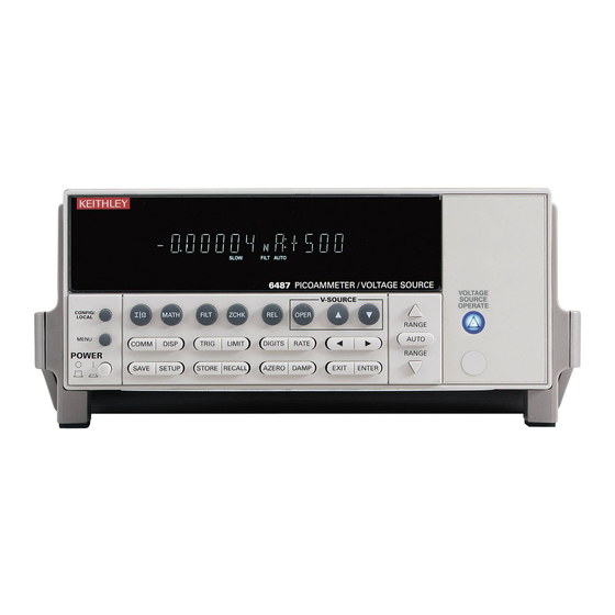
Model 6487 Reference Manual Front panel operation Figure 1-2 shows the front panel of the Model 6487. For a detailed description of the vari- ous controls, displays, and indicators, see Section 1 of the Model 6487 User’s Manual. Figure 1-2... -
Page 21: Front Panel Setup Operation
Section Restoring factory or GPIB default setups The SYSTem:PRESet command returns Model 6487 to the factory defaults and the *RST command returns it to the GPIB defaults. The *RST command is documented in Section 11 and SYSTem:PRESet is covered in... - Page 22 1-10 Getting Started Model 6487 Reference Manual Table 1-2 Default settings Factory GPIB Setting (:SYStem:PRESet) (*RST) Arm Layer (CONFIG ARM): Arm-In Source Event Arm Count Input Trigger Link Line Source Bypass NEVER Output Trigger Link Line Output Trigger Buffer (STORE):...
- Page 23 Model 6487 Reference Manual Getting Started 1-11 Table 1-2 (cont.) Default settings Factory GPIB Setting (:SYStem:PRESet) (*RST) Rate: Slow NPLC 6.0 (60Hz) or 5.0 (50Hz) Rel: Rel Value (VAL) RS-232: No effect (Off at factory) All Settings No effect Trigger Layer (CONFIG TRIG):...
-
Page 24: Menus
1-12 Getting Started Model 6487 Reference Manual Menus Main menus Many aspects of operation are configured through the main menus summarized in Table 1-3. Refer to the section listed in the table for in-depth information. To access the main menus, press the MENU key. Use the and RANGE keys to scroll through the menu items and the and cursor keys to change options. -
Page 25: Configuration Menus
Model 6487 Reference Manual Getting Started 1-13 Configuration menus Many keys have configuration menus that allow you to configure various Model 6487 operating modes. Table 1-4 summarizes the various configuration menus available. To access a configuration menu, press CONFIG and then the corresponding front panel key. -
Page 26: Scpi Programming
(?) that follows the command word. A query command requests (queries) the pro- grammed status of that command. When a query command is sent and the Model 6487 is addressed to talk, the response message is sent to the computer. -
Page 27: Measurement Concepts And Connections
Measurement Concepts and Connections • Connection fundamentals — Covers fundamental information about connecting test circuits to the picoammeter. • Basic connections to DUT — Details connecting test circuits to the picoammeter for both current and ohms measurements. • Using a test fixture —... -
Page 28: Connection Fundamentals
Measurement Concepts and Connections Model 6487 Reference Manual Connection fundamentals The following provides important fundamental information on input connections to the Model 6487. Typical connection drawings are provided in “Basic connections to DUT,” page 2-4. More detailed connections for specific measurements are in... -
Page 29: Maximum Input Levels
Model 6487 Reference Manual Measurement Concepts and Connections Maximum input levels The maximum input levels to the Model 6487 are summarized in Figure 2-2. t^okfkd The maximum safe voltage between the voltage source or ammeter common and chassis ground (common mode voltage) is 505V peak. -
Page 30: Voltage Source Test Leads
When using the voltage source, the test leads must be rated for 505V minimum and should include safety sheaths. These test leads are recommended for use with the Model 6487: Model 8606 High Performance Probe Tip Kit — Consists of two spade lugs, two alliga- tor clips, and two spring hook test probes. -
Page 31: Ohms Measurement Connections
Current limiting resistors are required for DUTs capable of forcing voltages 505V or greater. Damage to the instrument may result if volt- ages greater than 505V are forced on the Model 6487 INPUT HI. Ohms measurement connections Basic connections for ohms measurements are shown in Figure 2-4;... -
Page 32: Voltage Source Connections
505V. In the event that the resistance to be measured becomes shorted or an incorrect value of resistance is inserted in the test setup, the voltage source can permanently damage the Model 6487. To prevent this damage, the following steps should be taken as a protec- tion precaution. - Page 33 The 12.25MΩ in series will increase the measured resistance to 100.012GΩ The Model 6487 can be programmed to calculate the resistance and subtract the series resistance. Using the M/X+B function, in the example above, one would set M to 500, B to -14e6, and the units character to “omega”.
-
Page 34: Noise And Safety Shields
LO. Additionally, Figure 2-6(B) shows an added safety shield connected to earth ground and Model 6487 chassis. This type of shielding should be used whenever hazardous voltages will be present in the test circuit. t^okfkd The maximum safe voltage between picoammeter LO and chassis ground (common mode voltage) is 505V peak. -
Page 35: General Purpose Test Fixture
Model 6487 Reference Manual Measurement Concepts and Connections General purpose test fixture A general purpose test fixture is shown in Figure 2-7. This test fixture will accommodate a variety of connection requirements. Figure 2-7 General purpose test fixture connections Metal Chassis... - Page 36 2-10 Measurement Concepts and Connections Model 6487 Reference Manual Guard plate A metal guard plate will provide guarding or noise shielding for the DUT or test circuit. It will also serve as a mounting panel for DUT or test circuits. The guard plate must be insu- lated with appropriate spacing from the chassis of the test fixture commensurate with the external source used.
-
Page 37: Model 8009 Resistivity Test Fixture
Guarded electrodes that can accommodate samples up to 1/8” thick and 4” x 4”. • Safety Interlock: When properly connected to the Model 6487, the V-source goes into a high impedance state when the test fixture’s lid is opened. Note that this could leave a charged device in the fixture. -
Page 38: Floating Measurements
The maximum safe voltage between picoammeter LO and chassis ground (common mode voltage) is 505V. The Model 6487 does not internally limit the LO-to-chassis voltage. Exceeding 505V can create a shock hazard. -
Page 39: Interlock
2-13 Interlock The Model 6487 has a built-in interlock that works in conjunction with the voltage source. The interlock prevents the voltage source from being operated on the 50V and 500V ranges, and optionally on the 10V range, to assure safe operation. -
Page 40: Interlock Operation
2. Query can be used for all three source ranges: 10V, 50V, and 500V. Analog output The Model 6487 has an analog output on the rear panel. The ANALOG OUT provides a scaled, inverting ±2V output. A full-scale reading corresponds to ±2V output. - Page 41 Model 6487 Reference Manual Measurement Concepts and Connections 2-15 The 2V analog output signal is not corrected during calibration. Gain errors of up to 2.5% may appear at this output, depending on range. The output impedance is <100¾. To minimize the effects of loading, the input impedance of the device connected to the ANALOG OUT should be as high as possible.
-
Page 42: Measurement Considerations
Input bias current Offset current of Model 6487 could affect low current measurements. Voltage burden Offset voltage of Model 6487 could cause errors if it is high in relation to the voltage of the measured circuit. Noise Noise generated by source resistance and source capacitance. -
Page 43: Measurements And Sourcing Voltage
Measurements and Sourcing Voltage • Measurement overview — Explains the basic measurement and voltage source capabilities of Model 6487. • Performance considerations — Covers warm-up period, voltage offset correction, autozero, zero check, and zero correct. • Current measurements — Provides a basic procedure to measure current. -
Page 44: Measurement Overview
200uA ±210µA ±2.1mA 10nA 20mA ±21mA 100nA Voltage source The basic voltage source output capabilities of the Model 6487 are summarized in Table 3-2. Accuracy specifications are shown in Appendix Table 3-2 Basic voltage source output capabilities Range Maximum Output Step Size ±10.1V... -
Page 45: Performance Considerations
Performance considerations Warm-up period Model 6487 can be used within one minute after it is turned on. However, the instrument should be turned on and allowed to warm up for at least one hour before use to achieve rated accuracy. If the instrument has been exposed to extreme temperatures, allow extra time for the internal temperature to stabilize. -
Page 46: Zero Check And Zero Correct
Measurements and Sourcing Voltage Model 6487 Reference Manual SCPI programming Table 3-3 SCPI commands — autozero Command Description Default SYSTem SYSTem Subsystem: :AZERo [:STATe] <b> Enable or disable autozero. SYSTem:AZERo[:STATe] <b> Sending this command over the bus does not update the display while in remote. To verify the AZERo state, send the query. - Page 47 Measurements and Sourcing Voltage Zero correct klqb The Model 6487 saves a single Zero Correct value (not one for each range). For best results, acquire a new Zero Correct value after changing to the desired range. The Model 6487 has a zero correct feature to algebraically subtract the voltage offset term from the measurement (to actually reduce the voltage at the input terminals, see “Voltage...
- Page 48 Measurements and Sourcing Voltage Model 6487 Reference Manual SCPI programming — zero check and zero correct Table 3-4 SCPI commands — zero check and zero correct Commands Description Default SYSTem SYSTem Subsystem: :ZCHeck Zero check: [:STATe] <b> Enable or disable zero check. When Zero check is on, the reading on the display is replaced with ZEROCHK.
-
Page 49: Current Measurements
The LO to chassis breakdown voltage is 505V. Exceeding this voltage may cause damage to the instrument. The maximum input voltage and current to Model 6487 is 505V peak and 21mA. Exceeding either of these values may cause damage to the instrument that is not covered by the warranty. - Page 50 Measurements and Sourcing Voltage Model 6487 Reference Manual klqb After overloading with high voltage, it may take several minutes for the input current to drop to within specified limits. Input current can be verified by plac- ing the protection cap on the input connector and then use the ground link to connect COMMON and CHASSIS ground.
- Page 51 When not making floating measurements, it is recommended that you ground measurement LO at only one place in the circuit, such as with the ground link connection on the rear panel of the Model 6487. Fundamental information on making connections to the picoammeter input is...
- Page 52 The reading reflects what is applied to the input. While Model 6487 is busy performing measurements, the :DATA? command will not return the reading string until the instrument finishes and goes into the idle state.
-
Page 53: Programming Example
READ? ' Trigger and return one reading. Ohms measurements Overview To measure ohms with the Model 6487, you must set up the voltage source to the desired range, value, and current limit (see “Voltage source operation,” page 3-15), choose an appropriate current measurement range (or use auto range), and enable the ohms function. -
Page 54: Procedure
Measurements and Sourcing Voltage Model 6487 Reference Manual Procedure t^okfkd Always turn off the Model 6487 power before changing voltage source connections to avoid a possible shock hazard. Perform the following steps to measure resistance: Step 1. Set up voltage source Press either of the V-SOURCE adjustment keys, then use a manual RANGE key to set the voltage source range. - Page 55 Model 6487 Reference Manual Measurements and Sourcing Voltage 3-13 Step 7. Disable zero check and take a reading from the display Press ZCHK to disable zero check and display readings. If the readings are noisy, use fil- tering to reduce noise.
-
Page 56: Scpi Programming - Ohms Measurements
Use this command to turn the ohms function on or off. When the ohms function is enabled, the Model 6487 calculates the reading from the measured current and the voltage source setting: R = V/I. Additional OHMS commands control the alternate voltage ohms mode as described in “Alternating voltage ohms mode,”... -
Page 57: Programming Example - Ohms Measurements
3-15 Programming example — ohms measurements The following command sequence will perform one zero-corrected resistance measurement: *RST ' Return 6487 to GPIB defaults. FORM:ELEM READ,UNIT ' Measurement, units elements only. SYST:ZCH ON ' Enable zero check. RANG 2e-9 ' Select the 2nA range. -
Page 58: Sourcing Voltage
250µA 2.5mA Sourcing voltage t^okfkd Always turn off the Model 6487 power before changing voltage source connections to avoid a possible shock hazard. Perform the following steps to source voltage: Step 1. Set up voltage source Press either of the V-SOURCE adjustment keys, then use a manual RANGE key to set the voltage source range. - Page 59 Press the OPER key to turn on the voltage source output. The VOLTAGE SOURCE OPERATE indicator will turn on. `^rqflk Do not connect external sources to the 6487 voltage source. External sources may damage the 6487 voltage source. Figure 3-4...
-
Page 60: Operate Considerations
(REM annunciator on), assuming that the LLO (Local Lockout) function has not been employed. While in remote, the OPER key will only turn the source off. To turn it on, the Model 6487 must be in local (see Section Voltage source off state The voltage source is not in a high-impedance state when it is turned off. -
Page 61: Scpi Commands - Voltage Source
Model 6487 Reference Manual Measurements and Sourcing Voltage 3-19 SCPI commands — voltage source Table 3-8 SCPI commands — voltage source Commands Description Default SOURce[1] SOURce[1] subsystem: :VOLTage Voltage source commands: [:LEVel] [:IMMediate] [:AMPLitude] <NRf> Set output voltage level (-505V to +505V). -
Page 62: Programming Example - Voltage
Programming example — voltage The following command sequence will output 5V on the 10V range with a 2.5mA limit: *RST ' Return 6487 to GPIB defaults. SOUR:VOLT:RANG 10 ' Select 10V source range. SOUR:VOLT 5 ' Set voltage source output to 5. -
Page 63: Alternating Voltage Ohms Mode
Model 6487 Reference Manual Measurements and Sourcing Voltage 3-21 Alternating voltage ohms mode Overview Ohms can be measured in one of two ways: DC (normal) or alternating voltage (A-V). The alternating voltage ohms method is especially useful when the resistance or device being measured exhibits high background currents or high noise currents. - Page 64 3-22 Measurements and Sourcing Voltage Model 6487 Reference Manual Figure 3-6 shows a comparison of the A-V voltage and the resulting current. When the voltage first makes a transition from low to high or high to low, the current initially increases to maximum and then decays to its quiescent value.
-
Page 65: Storing A-V Ohms Readings
Enter the desired high voltage level, then press ENTER. The unit will prompt for the time that the voltage source value will be at each phase in the A-V cycle: TIME: 15.00 s Enter the desired time, then press ENTER. The Model 6487 will prompt for the one-shot mode: ONE-SHOT: YES... -
Page 66: Recalling A-V Ohms Readings
3-24 Measurements and Sourcing Voltage Model 6487 Reference Manual Set the desired number of A-V cycles, then press ENTER. The unit will prompt you as to whether or not you wish to clear the buffer automatically when a new A-V measurement is started: AUTOCLEAR: Y Select Y or N as desired, then press ENTER. -
Page 67: Operating Considerations
Model 6487 Reference Manual Measurements and Sourcing Voltage 3-25 Figure 3-8 A-V ohms reading recall sequence Reading Value (Amps) Reading Value (Ohms) Vsource Timestamp Timestamp Reading Value (Amps) Reading Value (Ohms) Vsource Timestamp Reading Value (Amps) Reading Value (Ohms) Vsource... - Page 68 3-26 Measurements and Sourcing Voltage Model 6487 Reference Manual Triggering considerations When A-V ohms is selected, the ARM-IN trigger source is forced to TIMER and the time interval selected will be slightly higher than that required for the A/D integration. For example, at 1 PLC the integration time is 16.67 msec, so sending the OHM:AVOL:ARM...
- Page 69 Model 6487 Reference Manual Measurements and Sourcing Voltage 3-27 data you have collected (easy to do, since STORE is located right next to RECALL). When working remotely, sending the TRAC:FEED:CONT NEXT command while there are A-V ohms readings in the buffer will result in a -225 “Out of Memory” error. Send TRAC:CLEar to clear out the buffer before attempting to store buffer readings.
-
Page 70: Scpi Commands - A-V Ohms
3-28 Measurements and Sourcing Voltage Model 6487 Reference Manual Interlock Attempting to run A-V ohms from the front panel while the interlock is open and failing will result in the error message “CLOSE INTLCK” being displayed. If trying to run remotely with the :ARM command the error event +802 “Output Blocked by Interlock”... - Page 71 Model 6487 Reference Manual Measurements and Sourcing Voltage 3-29 A) OHMS:AVOLtage[:ARM] This command arms the A-V ohms mode. Once this command is sent, the next INIT com- mand starts A-V readings. Sending this command, if there are normal readings in the buffer, results in error -225 “Out of Memory”.
- Page 72 3-30 Measurements and Sourcing Voltage Model 6487 Reference Manual E) OHMS:AVOLtage:POINts? This query returns the number of points per phase based on the user-supplied TIME value above. If the number of points would be greater than the maximum of 1,000 (for example, if you had set a new integration rate but not yet changed the AVOL:TIME value), then -999 will be returned.
-
Page 73: Programming Example - A-V Ohms Measurements
— A-V ohms measurements The following command sequence will perform A-V ohms measurements with a 5V high value, 10s per phase, and 5 A-V cycles: *RST ' Return 6487 to GPIB defaults. TRAC:CLE ' Clear buffer of all readings. RANG 20e-3 ' Select 20mA range (turn off auto). -
Page 74: Range, Units, Digits, Rate, And Filters
Range, Units, Digits, Rate, and Filters • Range, units, and digits — Provides details on measurement range, reading units, and display resolution selection. Includes the SCPI commands for remote operation. • Rate — Provides details on reading rate selection. Includes the SCPI commands for remote operation. -
Page 75: Range, Units, And Digits
Range, Units, Digits, Rate, and Filters Model 6487 Reference Manual Range, units, and digits Range The ranges for current measurements are listed in Table 4-1. Table 4-1 Measurement ranges μA 2μA 20nA 20μA 20mA 200nA 200μA The full scale readings for every measurement range are 5% over range. For example, on the 20µA range, the maximum input current is ±... -
Page 76: Units
Model 6487 Reference Manual Range, Units, Digits, Rate, and Filters Autorange limits Search time for amps can be reduced by setting upper and/or lower autorange limits. For example, if you know the maximum input will be around 1µA, set the upper current range limit to 2µA. -
Page 77: Digits
Range, Units, Digits, Rate, and Filters Model 6487 Reference Manual Digits The DIGITS key sets display resolution for the Model 6487. Display resolution can be set from 3 to 6 digits. This single global setting affects display resolution for all measure- ment ranges. - Page 78 Model 6487 Reference Manual Range, Units, Digits, Rate, and Filters Programming example — range and digits The following command sequence selects the 20mA range and sets display resolution to 3: *RST ' Restore RST defaults. CURR:RANG 0.02 ' Set to 20mA range.
-
Page 79: Rate
4-1. The Model 6487 is optimized for the 1 PLC to 10 PLC reading rate. At these speeds (lowest noise region in the graph), The Model 6487 will make correc- tions for its own internal drift and still be fast enough to settle a step response <100ms. -
Page 80: Scpi Programming - Rate
Model 6487 Reference Manual Range, Units, Digits, Rate, and Filters To change the rate setting, press (and release) the RATE key until the desired rate annunci- ator (SLOW, MED, or FAST) is displayed. NPLC Menu — From this menu you can set rate by setting the PLC value. Perform the following steps to set NPLC: Press CONFIG / LOCAL and then RATE to display the present PLC value. -
Page 81: Damping
Query damping filter state. Filters Filtering stabilizes noisy measurements caused by noisy input signals. The Model 6487 uses two types of filters: median and digital. The displayed, stored, or transmitted reading is simply the result of the filtering processes. Note that both the median and digital filters can be in effect at the same time. -
Page 82: Median Filter
Model 6487 Reference Manual Range, Units, Digits, Rate, and Filters Median filter The median filter is used to determine the "middle-most" reading from a group of readings that are arranged according to size. For example, assume the following readings: 20mA, 1mA, 3mA... -
Page 83: Digital Filter
4-10 Range, Units, Digits, Rate, and Filters Model 6487 Reference Manual Digital filter Digital filter types An additional filter parameter is type (type is either moving or repeating). Filter types are compared in Figure 4-2. Moving Filter — Every time a reading conversion occurs, the readings in the stack are averaged to yield a single filtered reading. - Page 84 Model 6487 Reference Manual Range, Units, Digits, Rate, and Filters 4-11 Response time The various filter parameters have the following effects on the time needed to display, store, or output a filtered reading: • Number of reading conversions — Speed and noise are tradeoffs.
-
Page 85: Scpi Programming - Filters
4-12 Range, Units, Digits, Rate, and Filters Model 6487 Reference Manual SCPI programming — filters Table 4-6 SCPI commands — filters Commands Description Default For median filter: [:SENSe[1]] SENSe Subsystem: :MEDian Median Filter: :RANK <n> Specify filter rank: 1 to 5. -
Page 86: Relative, Mx+B, M/X+B, And Log
Relative, mX+b, m/X+b, and log • Relative — Explains how to null an offset or establish a baseline value. Includes the SCPI commands for remote operation. • mX+b, m/X+b (reciprocal), and logarithmic — Covers these three basic math operations and includes the SCPI commands for remote operation. -
Page 87: Relative
Rel’ed reading. However, this does not increase the maximum allowable input for that range. An over-range input signal will still cause the display to overflow. For example, on the 20µA range, the Model 6487 still overflows for a 21µA input. klqb Rel can be used on the result of the mX+b, m/X+b, or LOG calculations. - Page 88 Model 6487 Reference Manual Relative, mX+b, m/X+b, and log Displaying or manually keying in REL Pressing CONFIG and then REL displays the present Rel value. This displayed Rel value can be enabled (pressing ENTER) or a different Rel value can be entered and enabled.
-
Page 89: Scpi Programming - Relative
Relative, mX+b, m/X+b, and log Model 6487 Reference Manual SCPI programming — relative Table 5-2 SCPI commands — relative (null) Commands Description Default CALCulate2 Path to configure and control limit testing (CALC2): :FEED <name> Specify reading to Rel: SENSe[1] or CALCulate[1]. -
Page 90: Mx+B, M/X+B (Reciprocal), And Logarithmic
Model 6487 Reference Manual Relative, mX+b, m/X+b, and log If the instrument is programmed to perform an infinite number of measurements (arm count or trigger count set to infinite), you cannot use the :DATA? command to return Rel’ed readings. However, you can use the :DATA:LATest? command to return the last Rel’ed reading after aborting the measurement process. -
Page 91: Logarithmic
This calculation converts input readings to logarithm base 10 values. The calculation is performed as follows: where: X is the input reading y is the logarithmic result For example: Assume that exactly 1mA is being measured by the Model 6487. 1.000000mA 3 – klqb This calculation uses the absolute value of the normal input reading, as the log of a negative number cannot be computed. -
Page 92: Scpi Programming - Mx+B, M/X+B, And Log
Model 6487 Reference Manual Relative, mX+b, m/X+b, and log To control log, perform the following steps: klqb Enabling or disabling math disables Rel (if Rel is enabled). Press CONFIG then MATH to enter the math configuration menu. Using either manual RANGE key, select MATH: LOG10, then press ENTER to select the log function. - Page 93 Relative, mX+b, m/X+b, and log Model 6487 Reference Manual C) :DATA? and :DATA:LATest? The INITiate command must be sent to trigger the measurements and calculations. The number of calculations depend on how many measurements the instrument is programmed to perform.
-
Page 94: Buffer And Sweeps
Buffer and Sweeps • Buffer operations — Explains how to store and recall readings including buffer statistics. • Voltage sweeps — Discusses how to generate sweeps using the voltage source. -
Page 95: Buffer Operations
Model 6487 Reference Manual Buffer operations The Model 6487 has a buffer to store from one to 3000 readings. It also stores overflow readings and the voltage source value. Each reading has a timestamp. The timestamp for each reading is referenced to the time the measure/store process is started. In addition, recalled data includes statistical information (maximum, minimum, peak-to-peak, average, and standard deviation). -
Page 96: Buffer Timestamps
Model 6487 Reference Manual Buffer and Sweeps Figure 6-1 Buffer locations Reading Value Vsource Timestamp Timestamp Reading Value Vsource Timestamp Reading Value Vsource Timestamp Reading Value Vsource Timestamp Reading Value Vsource Timestamp Reading Value Vsource Timestamp Reading Value Vsource RANGE... -
Page 97: Buffer Statistics
Buffer and Sweeps Model 6487 Reference Manual Buffer statistics • MIN and MAX provides the minimum and maximum readings stored in the buffer. It also indicates the buffer location of these readings. • The PK-PK (peak-to-peak) value is the difference between the maximum and... - Page 98 Model 6487 Reference Manual Buffer and Sweeps klqb The Model 6487 uses IEEE-754 floating point format for statistics calculations. When programming the buffer via remote, the trigger count set with the TRIG:COUN command should normally equal the number of buffer readings to store set with TRAC:POIN.
- Page 99 Buffer and Sweeps Model 6487 Reference Manual A) :TRACe:FREE? Two values, separated by commas, are returned. The first value indicates how many bytes of memory are available and the second value indicates how many bytes are reserved to store readings.
- Page 100 If there is a lot of data in the buffer, some statistic operations may take too long and cause a bus time-out error. To avoid this, send CALC3:DATA? and then wait for the MAV (message available) bit in the Status Byte Register to set before address- ing the Model 6487 talk (Section 10).
-
Page 101: Programming Example
' Request mean statistic. Voltage sweeps The Model 6487 voltage source can be used to generate voltage sweeps from a start volt- age to a stop voltage at discrete step voltages. The Model 6487 stores readings in the buffer for later recall, one set of readings per voltage step. - Page 102 Model 6487 Reference Manual Buffer and Sweeps The front panel sweep parameters are not error checked until you have entered a STEP value. If there are too many points, the error message “TOO MANY PTS” briefly appears and you will be taken back to the start (STRT) value entry menu.
-
Page 103: Sweep Operation
6-10 Buffer and Sweeps Model 6487 Reference Manual Sweep operation Using Table 6-2 as a guide, follow these steps to generate sweeps from the front panel: Press CONFIG then OPER. The unit will prompt for DC or SWEEP operation. Select SWEEP, then press ENTER. The unit will prompt for the STRT (start) voltage. -
Page 104: Sweep Example
Model 6487 Reference Manual Buffer and Sweeps 6-11 Source range The source range will be fixed at the lowest range required to properly handle all points in the sweep. For example, a 10-point sweep from +2V to +11 V in 1V steps will start on the 50V range and remain on the 50V range for all points in the sweep. -
Page 105: Scpi Programming - Sweeps
6-12 Buffer and Sweeps Model 6487 Reference Manual SCPI programming — sweeps Interlock Attempting to initialize a sweep over the front panel while the interlock is open and failing will result in the error message "CLOSE INTLCK" being displayed. If trying to arm remotely with the SOUR:VOLT:SWE:INIT command, the error event +802 "Output... - Page 106 Model 6487 Reference Manual Buffer and Sweeps 6-13 This example is the same as before except that a setting for the ARM layer count to infinite has been added. Now, after the INIT:IMM is received, the sweep will begin and all 11 points will be collected with no further commands required.
- Page 107 STARt and STOP and are another way to specify the sweep. F) :VOLTage:SWEep:DELay <NRf> This command programs the delay period, which is the time that the Model 6487 waits after sourcing the voltage before starting to take the measurement at each step.
-
Page 108: Programming Example
Programming example The following command sequence performs a sweep from 1V to 10V in 1V increments and recalls all readings: *RST ' Return 6487 to RST defaults. SOUR:VOLT:SWE:STAR 1 ' Start voltage = 1V. SOUR:VOLT:SWE:STOP 10 ' Stop voltage = 10V. -
Page 109: Triggering
— Includes the commands used to configure the trigger model and the commands to control the measurement process. • External triggering — Explains external triggering which allows the Model 6487 to trigger other instruments and to be triggered by other instruments. -
Page 110: Trigger Models
Trigger models The flowcharts in Figure 7-1 Figure 7-2 summarize triggering for the Model 6487. They are called trigger models because they are modeled after the SCPI commands to con- trol triggering (operation). Figure 7-1 Trigger model — front panel operation... - Page 111 SENSe | NONE TRIGger:DELay:AUTO <b> 0.0 sec MEASURE Note: The following commands place the Action Model 6487 into idle: ABORt, *RST, SYSTem:PRESet, *RCL <NRf>, = Output Trigger DCL, and SDC. The difference between front panel operation (Figure 7-1) and remote operation (Figure 7-2) is within the idle state of the instrument.
-
Page 112: Idle And Initiate
Typically, operation remains in the arm and trigger layers of the trigger model. However, the Model 6487 can be put into the idle state at any time by selecting HALT in the trigger configuration menu. To take the instrument out of idle, press the TRIG key. -
Page 113: Trigger Model Operation
Manual (ARM:SOURce MANual) — Event detection for the arm layer is satisfied • by pressing the TRIG key. The Model 6487 must be in the local mode for it to respond to the TRIG key. Press LOCAL or send LOCAL 14 over the bus to place the Model 6487 in local. - Page 114 A programmable delay is available after event detection. It can be set manually (0 to 999.9998 seconds) or an auto delay can be used. With auto delay selected, the Model 6487 automatically sets delay according to range. The auto delay settings are listed in Table 7-1.
- Page 115 CONV = Reading Conversion Output triggers The Model 6487 can send out an output trigger (via the rear panel TRIGGER LINK connector) right after the measure action and/or when operation leaves the trigger layer. An output trigger can be used to trigger another instrument to perform an operation (e.g., select the next output step for a source).
-
Page 116: Trigger Model Configuration - Front Panel
Triggering Model 6487 Reference Manual Trigger model configuration — front panel klqb See “SCPI Programming” (Table 7-3) for the SCPI commands to configure the trigger model over the bus. Press CONFIG and then TRIG to configure both the TRIG and ARM layers of the trigger model. - Page 117 Model 6487 Reference Manual Triggering Table 7-2 (cont.) Trigger model menu structure Menu Description - HALT Stops triggering. Press TRIG to resume. - ARM Path to ARM layer submenus. - - ARM-IN Path to ARM-IN control source. - - - IMM Set control source to IMMediate.
-
Page 118: Scpi Programming
7-10 Triggering Model 6487 Reference Manual SCPI programming Table 7-3 SCPI commands — triggering Command Description Default ABORt Reset trigger system (goes to idle state). INITiate Initiate one trigger cycle. FETCh? Request latest reading. READ? Trigger and request a “fresh” reading. -
Page 119: Programming Example
ABORt command and at the beginning of a program before sending a initiate command. (See “INITiate” command.) Programming example The following command sequence will trigger and return 10 readings. *RST ' Return 6487 to RST defaults. ARM:SOUR IMM ' Set arm control source Immediate. ARM:COUN 1 ' Set arm count to 1. -
Page 120: External Triggering
7-12 Triggering Model 6487 Reference Manual External triggering Input and output triggers are received and sent via the rear panel TRIGGER LINK connec- tor. The trigger link has six lines. At the factory line #2 is selected for output triggers and line #1 is selected for input triggers. -
Page 121: Output Trigger Specifications
DUT connected to that channel. Such a test system is shown in Figure 7-7. This example uses a Model 6487 to measure 10 DUTs switched by a Model 7158 low cur- rent card in a Model 7001 or 7002 switch system. Figure 7-7... - Page 122 Trigger Output Event = ON Trigger Count = 10 Trigger Delay = Auto To store readings in the Model 6487 buffer, first set the number of points to store in the buffer: Press CONFIG and then STORE. Set the buffer size to 10 using the RANGE and cursor keys.
- Page 123 Figure 7-9. Operation of the Model 6487 starts at point A in the flowchart where it waits for an external trigger. Pressing STEP takes Model 7001/7002 out of idle and places operation at point B in the flowchart.
- Page 124 Triggering Model 6487 Reference Manual The trigger applied to Model 7001/7002 from the Model 6487 closes the next channel in the scan, which then triggers the Model 6487 to measure that DUT. This process continues until all 10 channels are scanned and measured.
-
Page 125: Limit Tests And Digital I/O
Limit Tests and Digital I/O • Limit testing — Explains the basic Limit 1 and Limit 2 testing operations. • Binning — Explains how to use a component handler to perform binning operations. • Digital I/O port — Explains how to use the digital I/O port to control external circuitry. -
Page 126: Limit Testing
Limit Tests and Digital I/O Model 6487 Reference Manual Limit testing As shown in Figure 8-1, there are two limit tests that can be performed on a DUT. Limit 1 is used as the wide pass band and Limit 2 is used as the narrow pass band. It is up to the user to specify limits that conform to this pass band relationship. - Page 127 Model 6487 Reference Manual Limit Tests and Digital I/O The 2-stage limit testing process is shown in . If Limit 1 fails, the L1 message is displayed and the test is finished. Limit 2 is not tested because the pass band relationship between the two stages implies that if Limit 1 fails, Limit 2 must also fail.
- Page 128 Limit Tests and Digital I/O Model 6487 Reference Manual Figure 8-3 Operation model for limit test Start Measure Limit 1 Test Pass Display “L1” Limit 2 Test Display Pass “L2” Display “OK” klqb Display messages indicate which test or tests have failed, but they do not indicate which limit (HI or LO) has failed.
-
Page 129: Binning
Even though no additional equipment is required to perform limit tests on the DUT, the Model 6487 can be used with a component handler to perform binning operations. Based on the outcome of a test, the component handler will place the DUT in the assigned bin. - Page 130 Limit Tests and Digital I/O Model 6487 Reference Manual Figure 8-5 shows the basic limit testing flowchart expanded to include binning. Notice that there are five possible output patterns (one pass pattern and four fail patterns), but only one will be sent to the component handler for each DUT that is tested.
-
Page 131: Component Handler Interface
Model 6487 Reference Manual Limit Tests and Digital I/O Component handler interface The Model 6487 is interfaced to a component handler via the Digital I/O port as shown in Figure 8-6. (See “Digital I/O port,” page 8-11 for more information.) The I/O port has four lines for output signals and one line for input signals. -
Page 132: Component Handler Types
If the handler requires low-going pulses, then the four digital output lines of the Model 6487 must be initially set to high. This initial HI, HI, HI, HI clear pattern on the output lines represents a “no action” condition for the handler since it is waiting for one of the lines to go low. - Page 133 Limit Tests and Digital I/O Category register component handler When using this type of handler, the Model 6487 sends a bit pattern to three handler lines when a pass or fail condition occurs. This bit pattern determines the bin assignment for the DUT.
-
Page 134: Digital Output Clear Pattern
After every binning operation, the digital output needs to be reset to a clear pattern, which serves as a “no action” condition for the component handler. The Model 6487 can be programmed to automatically clear the digital output after the pass or fail pattern is sent. With auto-clear, you must specify the required pulse width (delay) for the pass or fail pattern. -
Page 135: Digital I/O Port
After the pass/fail is read by the handler, the digital output returns to the clear pattern. Digital I/O port The Model 6487's Digital I/O port is a male DB-9 connector located on the rear panel. The port location and pin designations are shown in Figure 8-8. -
Page 136: Sink Mode - Controlling External Devices
8-12 Limit Tests and Digital I/O Model 6487 Reference Manual • External device control — Each digital output can be used as a control switch for an external device (i.e. relay) circuit. Each output line can sink up to 500mA. Drive voltage is provided by an external source (+5V to +33V). - Page 137 Model 6487 Reference Manual Limit Tests and Digital I/O 8-13 `^rqflk Do not exceed +33V maximum voltage on pin 5 of the digital I/O port and do not use any output line to sink >500mA. Exceeding these limits may cause damage to the instrument that is not covered by the warranty.
-
Page 138: Source Mode - Logic Control
8-14 Limit Tests and Digital I/O Model 6487 Reference Manual Source mode — logic control The digital outputs can be used as logic inputs to active TTL, low-power TTL, or CMOS inputs. For this mode of operation, the output lines can source up to 2mA. -
Page 139: Scpi Programming - Digital Output Pattern
Model 6487 Reference Manual Limit Tests and Digital I/O 8-15 For example, to set output lines 3 and 1 HI (0101 bit pattern), set the output value to 5 (4 +1). Perform the following steps to set the digital output pattern from the front panel: Press CONFIG and then LIMIT to access the limits menu. -
Page 140: Front Panel Operation - Limit Tests
8-16 Limit Tests and Digital I/O Model 6487 Reference Manual Front panel operation — limit tests Limit test configuration Most aspects of limit testing are configured from the limit configuration menu. Once in a menu structure, use the cursor keys to display menu items. Use the cursor keys to key in values. -
Page 141: Performing Limit Tests
8-17 LIN4MOD (Line 4 Mode): • ENDOFTST (End of Test) — With this mode, Model 6487 will pulse the EOT line when the test is finished. Use with catagory register component handlers. • /BUSY and BUSY — Pulls line 4 LO (/Busy) or HI (Busy) while the test is in pro- cess. -
Page 142: Scpi Programming - Limit Tests
8-18 Limit Tests and Digital I/O Model 6487 Reference Manual SCPI programming — limit tests Table 8-3 Limit test commands Command Description Default :CALCulate2 CALCulate2 Subsystem: :FEED <name> Select input path for limit testing: CALCulate[1] SENS or SENSe[1]. :LIMit[1] Limit 1 Testing:... - Page 143 Model 6487 Reference Manual Limit Tests and Digital I/O 8-19 Table 8-3 (cont.) Limit test commands Command Description Default Ref :SOURce2 SOURce2 Subsystem: :TTL <NDN> or <NRf> Specify 4-bit digital output clear pattern. :CLEar Clear I/O port (return output to TTL pattern): [:IMMediate] Clear I/O port immediately.
- Page 144 8-20 Limit Tests and Digital I/O Model 6487 Reference Manual B) <NDN> and <NRf> parameters <NDN> = #Bxxxx Binary format (each x = 1 or 0) = #Hx Hexadecimal format (x = 0 to F) = #Qxx Octal format (x = 0 to 17) <NRf>...
-
Page 145: Programming Example
Model 6487 Reference Manual Limit Tests and Digital I/O 8-21 If the instrument is programmed to perform an infinite number of measurements (arm count or trigger count set to infinite), you cannot use the :DATA? command to return CALC2 readings. However, you can use the :DATA:LATest? command to return the last CALC2 reading after aborting the measurement process. -
Page 146: Remote Operation
Remote Operation • Selecting and configuring an interface — Explains how to select and configure an interface: GPIB or RS-232. • GPIB operation and reference — Covers the following GPIB topics: GPIB bus standards GPIB bus connections Primary address General IEEE-488 bus commands Front panel GPIB operation Programming syntax •... -
Page 147: Selecting And Configuring An Interface
GPIB interface — The GPIB is the IEEE-488 interface. The Model 6487 must be assigned to a unique address. At the factory the address is set to 22, but can be set to any value from 0 to 30. -
Page 148: Interface Selection And Configuration Procedures
Model 6487 Reference Manual Remote Operation Interface selection and configuration procedures klqb The unit will reset if the language is changed (SCPI, 488.1, and DDC). When you select (enable) the GPIB interface, the RS-232 interface disables. Conversely, selecting (enabling) the RS-232 interface disables the GPIB interface. -
Page 149: Gpib Operation And Reference
IEEE-488.2-1992 and defines a standard set of commands to control every programmable aspect of an instrument. GPIB bus connections To connect the Model 6487 to the GPIB bus, use a cable equipped with standard IEEE-488 connectors as shown in Figure 9-1. - Page 150 Earlier versions had dif- ferent screws, which were silver-colored. Do not use these types of connectors on the Model 6487, because it is designed for metric threads. Figure 9-2 shows a typical connecting scheme for a multi-unit test system.
-
Page 151: Primary Address
Primary address The Model 6487 ships from the factory with a GPIB address of 22. When the instrument powers up, it momentarily displays the primary address. You can set the address to a value of 0-30. Do not assign the same address to another device or to a controller that is on the... -
Page 152: General Ieee-488 Bus Commands
Serial polls Model 6487. REN (remote enable) The remote enable command is sent to the Model 6487 by the controller to set up the instrument for remote operation. Generally, the instrument should be placed in the remote mode before you attempt to program it over the bus. Simply setting REN true does not actually place the instrument in the remote state. - Page 153 DCL. GET (group execute trigger) GET is a GPIB trigger that is used as an event to control operation. The Model 6487 reacts to this trigger if it is the programmed control source. The control source is programmed...
-
Page 154: Front Panel Gpib Operation
Remote Operation SPE, SPD (serial polling) Use the serial polling sequence to obtain the Model 6487 serial poll byte. The serial poll byte contains important information about internal functions. Generally, the serial polling sequence is used by the controller to determine which of several instruments has requested service with the SRQ line. -
Page 155: Programming Syntax
9-10 Remote Operation Model 6487 Reference Manual LOCAL key The LOCAL key cancels the remote state and restores local operation of the instrument. Pressing the LOCAL key also turns off the REM indicator and returns the display to nor- mal if a user-defined message was displayed. If the unit is in local (not in remote), the LOCAL key acts as a configure key (see “Front panel operation,”... - Page 156 Model 6487 Reference Manual Remote Operation 9-11 <name> Name parameter — Select a parameter name from a listed group. <name> = NEVer = NEXT :CALCulate:FORMat MXB Select Mx + B calculation <NRf> Numeric representation format — A number that can be expressed as an integer (e.g., 8), a real number (e.g., 23.6), or an exponent...
- Page 157 9-12 Remote Operation Model 6487 Reference Manual Query commands The query command requests the presently programmed status. It is identified by the ques- tion mark (?) at the end of the fundamental form of the command. Most commands have a query form.
- Page 158 Model 6487 Reference Manual Remote Operation 9-13 These rules apply to command words that exceed four letters: • If the fourth letter of the command word is a vowel, delete it and all letters after it. immediate = :imm •...
- Page 159 9-14 Remote Operation Model 6487 Reference Manual Multiple command messages You can send multiple command messages in the same program message as long as they are separated by semicolons (;). The following is an example showing two commands in one program message: :stat:oper;...
- Page 160 9-14), the multiple response messages for all the queries is sent to the computer when the Model 6487 is addressed to talk. The responses are sent in the order that the query commands were sent and are separated by semicolons (;). Items within the same query are separated by commas (,).
-
Page 161: Rs-232 Interface Reference
Model 6487. This clears any pending operation and discards any pending output. Baud rate The baud rate is the rate at which the Model 6487 and the programming terminal commu- nicate. You can choose from one of the following rates: 57.6k, 38.4k, 19.2k, 9600, 4800, 2400, 1200, 600, or 300. - Page 162 9-17 Make sure that the programming terminal that you are connecting to the Model 6487 can support the baud rate you selected. Both the Model 6487 and the other device must be con- figured for the same baud rate. Data and stop bits The RS-232 can be set to transfer data using seven or eight data bits and one stop bit.
-
Page 163: Rs-232 Connections
RTS, request to send CTS, clear to send No connections RTS and CTS are tied together. DCD, DTR, and DSR are tied together. TXD and RXD are swapped on Model 6487 and PC so that null modem cable is not required. -
Page 164: Error Messages
Model 6487 Reference Manual Remote Operation 9-19 Table 9-3 PC serial port pinout DB-9 DB-25 Signal pin number pin number DCD, data carrier detect RXD, receive data TXD, transmit data DTR, data terminal ready GND, signal ground DSR, data set ready... -
Page 165: Status Structure
Status Structure • Overview — Provides an operational overview of the status structure for the Model 6487. • Clearing registers and queues — Covers the actions that clear (reset) registers and queues. • Programming and reading registers — Explains how to program enable registers and read any register in the status structure. -
Page 166: Overview
Queues — The Model 6487 uses an output queue and an error queue. The response mes- sages to query commands are placed in the output queue. As various programming errors and status messages occur, they are placed in the error queue. - Page 167 Model 6487 Reference Manual Status Structure 10-3 Figure 10-1 Model 6487 status mode structure Questionable Event Registers Condition Event Event Enable Register Register Register & & & & & & & Logical Calibration Summary & & & & & Error Queue &...
-
Page 168: Clearing Registers And Queues
Model 6487 Reference Manual Clearing registers and queues When the Model 6487 is turned on, the bits of all registers in the status structure are clear (reset to 0) and the two queues are empty. Commands to reset the event and event enable... -
Page 169: Programming And Reading Registers
Model 6487 Reference Manual Status Structure 10-5 Programming and reading registers Programming enable registers The only registers that can be programmed by the user are the enable registers. All other registers in the status structure are read-only registers. The following explains how to ascertain the parameter values for the various commands used to program enable registers. -
Page 170: Reading Registers
10-6 Status Structure Model 6487 Reference Manual mat) parameter type is used to send decimal values and does not use a header. The follow- ing examples show the proper parameter syntax for setting bits B5, B3, and B2: #b101100 Binary format (<NDN> parameter type) #h2C Hexadecimal format (<NDN>... -
Page 171: Status Byte And Service Request (Srq)
Model 6487 Reference Manual Status Structure 10-7 Status byte and service request (SRQ) Service request is controlled by two 8-bit registers: the status byte register and the service request enable register. Figure 10-3 shows the structure of these registers. Figure 10-3... -
Page 172: Service Request Enable Register
(RQS) bit or the master summary status (MSS) bit: • When using the serial poll sequence of the Model 6487 to obtain the status byte (a.k.a. serial poll byte), B6 is the RQS bit. See “Serial polling and SRQ,” page 10-9 for details on using the serial poll sequence. -
Page 173: Serial Polling And Srq
Typically, SRQs are managed by the serial poll sequence of the Model 6487. If an SRQ does not occur, bit B6 (RQS) of the status byte register will remain cleared and the pro- gram will simply proceed normally after the serial poll is performed. -
Page 174: Status Register Sets
Command errors include: — IEEE-488.2 syntax error — The Model 6487 received a message that does not fol- low the defined syntax of the IEEE-488.2 standard. — Semantic error — The Model 6487 received a command that was misspelled or received an optional IEEE-488.2 command that is not implemented. - Page 175 Bit B6, user request (URQ) — Set bit indicates that the LOCAL key on the Model 6487 front panel was pressed. Bit B7, power ON (PON) — Set bit indicates that Model 6487 has been turned off • and turned back on since the last time this register has been read.
-
Page 176: Operation Event Status
TLINK trigger event to occur. • Bit B6, waiting for arm event (Arm) — Set bit indicates that the Model 6487 is in the arm layer waiting for an arm event to occur. -
Page 177: Measurement Event Status
Model 6487 Reference Manual Status Structure 10-13 Measurement event status The used bits of the measurement event register (Figure 10-6) are described as follows: • Bit B1, low limit 1 fail (LL1F) — Set bit indicates that the low limit 1 test has failed. - Page 178 • Bit B7, reading overflow (ROF) — Set bit indicates that the reading exceeds the selected measurement range of the Model 6487. • Bit B8, buffer available (BAV) — Set bit indicates that there are at least two readings in the buffer.
- Page 179 For example, while the Model 6487 is in the idle state, bit B10 (Idle) of the operation condition register will be set. When the instrument is taken out of idle, bit B10 clears.
- Page 180 10-16 Status Structure Model 6487 Reference Manual Event registers Figure 10-1 shows, each status register set has an event register. When an event occurs, the appropriate event register bit sets to 1. The bit remains latched to 1 until the register is reset.
-
Page 181: Queues
' Read Measurement Condition Register. STAT:MEAS? ' Read Measurement Event Register. Queues The Model 6487 uses two queues which are first-in, first-out (FIFO) registers: • Output queue — Used to hold reading and response messages. • Error queue — Used to hold error and status messages. -
Page 182: Output Queue
An empty output queue clears the MAV bit in the status byte register. A message is read from the output queue by addressing the Model 6487 to talk after the appropriate query is sent. -
Page 183: Error Queue
When empty, the message “0, No Error” is placed in the queue. Messages in the error queue are preceded by a code number. Negative (-) numbers are used for SCPI defined messages and positive (+) numbers are used for Keithley defined messages. The messages are listed in Appendix B. - Page 184 10-20 Status Structure Model 6487 Reference Manual Table 10-7 SCPI commands — error queue Command Description Default STATus STATus subsystem: :QUEue Read error queue: (Note 1) [:NEXT]? Read and clear oldest error/status (code and message). :ENABle <list> Specify error and status messages for error queue.
-
Page 185: Common Commands
Common Commands • Common commands — This section lists and describes the common commands. - Page 186 *OPT? Option query Returns model number of any installed options. *RCL <NRf> Recall command Returns Model 6487 to the user-saved setup. *RST Reset command Returns Model 6487 to the *RST default conditions. *SAV <NRf> Save command Saves the present setup as the user-saved setup.
- Page 187 The identification code includes the manufacturer, model number, serial number, and firm- ware revision levels and is sent in the following format: KEITHLEY INSTRUMENTS INC., MODEL 6487, xxxxxxx, yyyyy/zzzzz/w Where: xxxxxxx is the serial number. yyyyy/zzzzz is the firmware revision levels of the digital board ROM and display board ROM.
- Page 188 E) TRG — trigger Send bus trigger to Model 6487 Use the *TRG command to issue a GPIB trigger to the Model 6487. It has the same effect as a group execute trigger (GET). Use the *TRG command as an event to control operation. The Model 6487 reacts to this trigger if BUS is the programmed arm control source.
- Page 189 Use this query command to perform a checksum test on ROM. The command places the coded result (0 or 1) in the output queue. When the Model 6487 is addressed to talk, the coded result is sent from the output queue to the computer.
-
Page 190: Scpi Signal Oriented Measurement Commands
SCPI Signal Oriented Measurement Commands... - Page 191 If the instrument is in idle, this command will execute immediately. If the instrument is not in idle, execution of the command will execute when the operation returns to the idle state. When this command is executed, the Model 6487 will be configured as follows: •...
- Page 192 Request latest reading This command requests the latest post-processed readings. After sending this command and addressing the Model 6487 to talk, the readings are sent to the computer. This com- mand does not affect the instrument setup. This command does not trigger a measurement. The command simply requests the last group of readings.
- Page 193 12-4 SCPI Signal Oriented Measurement Commands Model 6487 Reference Manual D) MEASure[:<function>]? Configure and perform “one-shot” measurement <function> = CURRent[:DC] Measure current This command combines all of the other signal oriented measurement commands to per- form a “one-shot” measurement and acquire the reading.
-
Page 194: Display, Format, And System
DISPlay, FORMat, and SYSTem • DISPlay subsystem — Covers the SCPI commands that are used to control the display. • FORMat subsystem — Covers the SCPI commands to configure the format that readings are sent over the bus. • SYSTem subsystem —... -
Page 195: Display Subsystem
13-2 DISPlay, FORMat, and SYSTem Model 6487 Reference Manual DISPlay subsystem The commands in this subsystem are used to control the display over the bus. Table 13-1 SCPI commands — display Command Description Default :DISPlay :DIGits <n> Set display resolution: 4 to 7. - Page 196 Model 6487 Reference Manual DISPlay, FORMat, and SYSTem 13-3 B) DISPlay:TEXT[:DATA] <a> Message Types: String ‘aa…a’ or “aa…a” Indefinite Block #0aa…a Definite Block #XYaa…a where: Y = number of characters in message (up to 12) X = number of digits that make up Y (1 or 2) The display message can be up to 12 characters (ASCII) long.
-
Page 197: Format Subsystem
<length> is not used for the ASCii or SREal parameters. It is optional for the REAL parameter. If you do not use <length> with REAL, <length> defaults to 32 (single precision format). The double precision format (<length> = 64) is not supported by Model 6487. - Page 198 Model 6487 Reference Manual DISPlay, FORMat, and SYSTem 13-5 The response to READ?, FETCh?, MEASure?, TRACe:DATA?, CALC1:DATA?, CALC2:DATA?, or CALC3:DATA? over the GPIB can be returned in either the ASCii or binary format. All other queries are returned in ASCii, regardless of the selected format.
- Page 199 The header and terminator are sent only once for each READ?. During binary transfers, never un-talk Model 6487 until after the data is read (input) to the computer. Also, to avoid erratic operation, the readings of the data string (and terminator) should be acquired in one piece.
- Page 200 (delta format). The TRACe:TSTamp:FORMat command is used to select the timestamp format. Status — The status word provides information about Model 6487 operation. The 16-bit status word is sent in decimal form. The decimal value has to be converted to the binary equivalent to determine the state of each bit in the word.
- Page 201 13-8 DISPlay, FORMat, and SYSTem Model 6487 Reference Manual Bit 2 (Math) — Set to 1 when measurement performed with CALC1 enabled. Bit 3 (Null) — Set to 1 if null for CALC2 is enabled. Bit 4 (Limits) — Set to 1 if a limit test (CALC2) is enabled.
-
Page 202: System Subsystem
Model 6487 Reference Manual DISPlay, FORMat, and SYSTem 13-9 SYSTem subsystem Table 13-3 SCPI commands — system Command Description Default :SYSTem :ZCHeck Zero check: Section 3 [:STATe] <b> Enable or disable zero check. [:STATe? Query zero check state. :ZCORrect Zero correct: Section 3 [:STATe] <b>... - Page 203 Resets the absolute timestamp to 0 seconds. The timestamp also resets when power is cycled or after the instrument is on for 99,999.99 seconds. The TRACe:TSTamp:FORMat command is used to select the absolute timestamp. See the Model 6487 User’s Manual for details.
- Page 204 When :SYST:KEY? is sent and Model 6487 is addressed to talk, the key-press code num- ber for the last :SYST:KEY command is sent to the computer. The value is -1 if a :SYST:KEY command has not been sent since the last time the unit was placed in remote.
-
Page 205: Scpi Reference Tables
SCPI Reference Tables • Table 14-1 — CALCulate command summary • Table 14-2 — DISPlay command summary • Table 14-3 — FORMat command summary • Table 14-4 — SENSe command summary • Table 14-5 — SOURce command summary • Table 14-6 —... -
Page 206: General Notes
14-2 SCPI Reference Tables Model 6487 Reference Manual General notes • Brackets ([ ]) are used to denote optional character sets. These optional characters do not have to be included in the program message. Do not use brackets in the pro- gram message. - Page 207 Model 6487 Reference Manual SCPI Reference Tables 14-3 Table 14-1 (cont.) CALCulate command summary Default Command Description parameter Section SCPI :CALCulate[1] :KMATh :MA0Factor <NRf> Set “b” for mX+b and m/X+b calculation (same as MBFactor). :MA0Factor? Query “b” factor (same as MBFactor?).
- Page 208 14-4 SCPI Reference Tables Model 6487 Reference Manual Table 14-1 (cont.) CALCulate command summary Default Command Description parameter Section SCPI √ :SOURce2? Query output pattern value. √ :STATe <b> Enable or disable limit 1 test. √ :STATe? Query state of limit 1 test.
- Page 209 Model 6487 Reference Manual SCPI Reference Tables 14-5 Table 14-1 (cont.) CALCulate command summary Default Command Description parameter Section SCPI :SOURce2 <NDN> or Set 4-bit “pass” pattern. (see <NRf> note) :SOURce2? Query output bit pattern. √ :DATA? Return all CALC2 readings triggered by INI- Tiate.
- Page 210 14-6 SCPI Reference Tables Model 6487 Reference Manual Table 14-2 DISPlay command summary Default Command Description parameter Section SCPI :DISPlay :DIGits <n> Set display resolution: 4 to 7. :DIGits? Query display resolution. √ :ENABle <b> Turn front panel display on or off.
- Page 211 Model 6487 Reference Manual SCPI Reference Tables 14-7 Table 14-3 FORMat command summary Default Command Description parameter Section SCPI :FORMat √ [:DATA] Specify data format; ASCii, REAL, 32, or <type>[,<length>] SREal. √ [:DATA]? Query data format. :ELEMents <item list> Specify data elements; READing, UNITs, All except VSOurce, TIME, STATus, DEFault, and ALL.
- Page 212 14-8 SCPI Reference Tables Model 6487 Reference Manual Table 14-4 (cont.) SENSe command summary Default Ref. Command Description parameter Section SCPI [:SENSe[1]] [:CURRent[:DC]] √ :RANGe Configure measurement range: √ [:UPPer] <NRf> Select range: -0.021 to 0.021 (amps). 2.1e-4 √ [:UPPer]? Query range value.
- Page 213 Model 6487 Reference Manual SCPI Reference Tables 14-9 Table 14-4 (cont.) SENSe command summary Default Ref. Command Description parameter Section SCPI [:DAMPing] :OHMS Path to control ohms: [:STATe] <b> Enable or disable ohms for SENSe1 data. [:STATe]? Query ohms SENSe1 data state.
- Page 214 14-10 SCPI Reference Tables Model 6487 Reference Manual Table 14-5 SOURce command summary Default Ref. Command Description parameter Section SCPI :SOURce[1] SOURce1 subsystem: :VOLTage Path to voltage source commands. [:LEVel] [:IMMediate] [:AMPLitude] Set voltage source amplitude (-500 to <NRf> 500).
- Page 215 Model 6487 Reference Manual SCPI Reference Tables 14-11 Table 14-5 (cont.) SOURce command summary Default Ref. Command Description parameter Section SCPI :SOURce[1] :VOLTage :SWEep Sweep commands: :STARt <NRf> Program start voltage: -505V to 505V. :STARt? Query start voltage. :STOP <NRf>...
- Page 216 14-12 SCPI Reference Tables Model 6487 Reference Manual Table 14-5 (cont.) SOURce command summary Default Ref. Command Description parameter Section SCPI :AUTO? Query auto-clear state. :DELay <n> Specify delay (pulse width) for pass/fail 0.0001 pattern: 0 to 60 (sec). :DELay? Query delay value.
- Page 217 Model 6487 Reference Manual SCPI Reference Tables 14-13 Table 14-6 STATus command summary Default Command Description parameter Section SCPI √ :STATus (Note 1) :MEASurement Measurement event registers: [:EVENt]? Read the event register. (Note 2) :ENABle <NDN> or Program the enable register.
- Page 218 14-14 SCPI Reference Tables Model 6487 Reference Manual Table 14-6 (cont.) STATus command summary Default Command Description parameter Section SCPI :DISable <list> Specify messages not to be placed in queue. (Note 5) :DISable? Read the disabled messages. :CLEar Clear messages from error queue.
- Page 219 Model 6487 Reference Manual SCPI Reference Tables 14-15 Table 14-7 SYSTem command summary (see Section 13 for detailed information) Default Command Description parameter Section SCPI :SYSTem :ZCHeck Zero check: [:STATe] <b> Enable or disable zero check. [:STATe]? Query state of zero check.
- Page 220 RS-232 interface: :LOCal While in LLO, removes the LLO and places the Model 6487 in local (RS-232 only). :REMote Places the Model 6487 in remote if not in LLO (RS-232 only). :RWLock Places the Model 6487 in local lockout (RS-232 only).
- Page 221 Model 6487 Reference Manual SCPI Reference Tables 14-17 Table 14-8 TRACe command summary Default Command Description parameter Section SCPI √ :TRACe|:DATA Use :TRACe or :DATA as root command. Note √ :DATA? [BUFFER] Read the contents of normal or A-V ohms BUFFER buffer.
- Page 222 14-18 SCPI Reference Tables Model 6487 Reference Manual Table 14-9 TRIGger command summary Default Command Description parameter Section SCPI √ :INITiate Path to initiate measurement cycle(s): √ [:IMMediate] Initiate one trigger cycle. √ :ABORt Reset trigger system (goes to idle state).
- Page 223 Model 6487 Reference Manual SCPI Reference Tables 14-19 Table 14-9 (cont.) TRIGger command summary Default Command Description parameter Section SCPI √ :TRIGger Trigger layer: :CLEar Clear pending input trigger immediately. [:SEQuence[1]] Trigger path. √ :SOURce <name> Select control source: IMMediate or TLINk.
-
Page 224: Performance Verification
Performance Verification • Verification test requirements — Summarizes environmental conditions, warm- up period, and line power requirements. • Recommended test equipment — Lists all equipment necessary for verification and gives pertinent specifications. • Verification limits — Describes how reading limits are calculated and gives an example. -
Page 225: Introduction
15-2 Performance Verification Model 6487 Reference Manual Introduction Use the procedures in this section to verify that Model 6487 accuracy is within the limits stated in the instrument’s one-year accuracy specifications. You can perform these verifica- tion procedures: • When you first receive the instrument to make sure that it was not damaged during shipment. -
Page 226: Warm-Up Period
Allow the test equipment to warm up for the minimum time specified by the manufacturer. Line power The Model 6487 requires a line voltage of 100 to 120V or 220 to 240V at a line frequency of 50 to 60Hz. Verification tests must be performed within this range. Be sure the line volt-... - Page 227 15-4 Performance Verification Model 6487 Reference Manual Table 15-1 Recommended performance verification equipment Description Manufacturer/Model Specifications Calibrator Fluke 5700A DC Voltage: 2V: 7ppm 20V: 5ppm 200V: 7ppm DC Current: 20μA: 550ppm 200μA: 100ppm 2mA: 55ppm 20mA: 55ppm Electrometer Calibration Keithley Model 5156...
-
Page 228: Verification Limits
15-5 Verification limits The verification limits stated in this section have been calculated using only Model 6487 one-year accuracy specifications and they do not include test equipment uncertainty. If a particular measurement falls outside the allowable range, recalculate new limits based on both Model 6487 specifications and corresponding test equipment specifications. -
Page 229: Performing The Verification Test Procedures
Test considerations When performing the verification procedures: • Be sure to restore Model 6487 factory front panel defaults and perform voltage off- set calibration as outlined below. • Make sure that the test equipment is properly warmed up and properly connected to the correct Model 6487 terminal(s). -
Page 230: Offset Voltage Calibration
15-1). Use the appropriate coax cable, triax-to BNC adapter, and BNC-to- dual banana plug adapter where shown. Turn on the Model 6487 and calibrator. Allow them to warm up for one hour. Set the Model 6487 to the 20μA range using the up or down RANGE key. -
Page 231: 2Na-2Μa Range Accuracy
(Figure 15-2). Initially, make connections to the 1GΩ resistor in the calibration standard. Turn on the Model 6487 and calibrator power. Allow them to warm up for one hour. Set the Model 6487 to the 2nA range. With zero check enabled, zero correct the instrument and then disable zero check. - Page 232 • Set the calibrator to the calculated voltage. • Verify that the Model 6487 current reading is within the reading limits listed in the table. Repeat the procedure for negative source currents with the same magnitudes as those listed in Table 15-3.
-
Page 233: Voltage Source Output Accuracy
Model 5156 Calibration Standard Voltage source output accuracy Follow the steps below to verify that Model 6487 voltage source output accuracy is within specified limits. The test involves setting the voltage source output to specific values and then verifying that DMM voltage readings are within required limits. - Page 234 Verify voltage source accuracy for each of the values listed in Table 15-4. For each test point: • Select the correct Model 6487 voltage source range. • Set the voltage source output to the indicated value. • Make sure the voltage source is in operate (output on).
-
Page 235: Calibration
— Lists considerations to take into account when calibrating the unit. • Calibration cycle — States how often the Model 6487 should be calibrated. • Recommended calibration equipment — Lists all equipment necessary for cali- bration and gives pertinent specifications. -
Page 236: Introduction
Allow the test equipment to warm up for the minimum time specified by the manufacturer. Line power The Model 6487 requires a line voltage of 100 to 120V or 220 to 240V at a line frequency of 50 to 60Hz. The instrument must be calibrated while operating from a line voltage within this range. -
Page 237: Calibration Considerations
• Always allow the source signal to settle before calibrating each point. • Do not connect test equipment to the Model 6487 through a scanner or other switching equipment. • If an error occurs during calibration, the Model 6487 will generate an appropriate error message. -
Page 238: Calibration Errors
One-year, DMM accuracy specifications at specified voltage and range. Calibration errors The Model 6487 checks for errors after each calibration step, minimizing the possibility that improper calibration may occur due to operator error. If an error is detected during calibration, the instrument will display an appropriate error message. The unit will then... -
Page 239: Calibration Menu
Model 6487 Reference Manual Calibration 16-5 Table 16-2 Current test uncertainty ratios with recommended equipment Test uncertainty Range 5700 + 5156 ratio 7ppm + 300ppm 13.0 20nA 7ppm + 200ppm 19.3 200nA 5ppm + 200ppm 2μA 7ppm + 200ppm 20μA 550ppm 200μA... -
Page 240: Aborting Calibration
16-6 Calibration Model 6487 Reference Manual Table 16-4 Calibration menu Menu Item* Description VOFFSET Performs offset voltage calibration. COUNT Displays calibration count. Calibrates present current range. VSRC-RUN Calibrates present voltage source range. DATES Displays calibration and due dates. UNLOCK Unlocks calibration using code. -
Page 241: Calibration Procedure
• Locking out calibration Preparing for calibration Turn on the Model 6487 and the calibrator; allow them to warm up for at least one hour before performing calibration. Press MENU, select CAL, then press ENTER. The instrument will display the... -
Page 242: Current Calibration
Model 6487 Reference Manual Current calibration 20μA-20mA range calibration Connect the triax shielding cap to the Model 6487 rear panel INPUT jack. Select the Model 6487 20μA range. Press MENU, select CAL, then press ENTER. At the CAL: RUN prompt, press ENTER. - Page 243 Adapter Output LO to shield. 2nA-2μA range calibration Connect the voltage calibrator and the Model 5156 Electrometer Calibration Standard to the Model 6487 INPUT jack (Figure 16-2). Initially, make connections to the 1GΩ resistance. Set the calibrator to output volts and make sure the calibrator output is turned on.
- Page 244 Set the calibrator voltage to +2.000000V. Calculate the actual calibration current from the calibrator voltage and the actual standard resistor value: I = V/R. Adjust the Model 6487 display to agree with the calculated current, then press ENTER. The Model 6487 will prompt for the negative full-scale calibration point: -2NA CAL Press ENTER.
- Page 245 Model 6487 Reference Manual Calibration 16-11 Table 16-6 2nA to 2µA range calibration summary Model 6487 range Calibrator voltages Standard resistors Calibration currents 1GΩ +2.000000V 1GΩ +2nA -2.000000V 1GΩ -2nA 20nA 100MΩ +2.000000V 100MΩ +20nA -2.000000V 100MΩ -20nA 2μA 100MΩ...
-
Page 246: Voltage Source Calibration
-10.00000 V Note the DMM voltage reading. Adjust the Model 6487 display to agree with that voltage and then press ENTER. Operate will turn off and the instrument will prompt for the zero calibration point: V: 10V ZERO Press ENTER. -
Page 247: Entering Calibration Dates And Saving Calibration
Model 6487 Reference Manual Calibration 16-13 Table 16-7 Voltage source calibration summary Model 6487 Range Calibration Voltages* -10.00000V +0.00000V +10.0000V -50.00000V +0.00000V +50.00000V 500V -500.0000V +0.00000V +500.0000V * Nominal values. Adjust display to agree with DMM reading. Figure 16-3 Connections for voltage source calibration... -
Page 248: Locking Out Calibration
16-14 Calibration Model 6487 Reference Manual Set the calibration due date as desired then press ENTER. The unit will prompt you as follows: SAVE CAL?YES With the YES prompt displayed, press ENTER to save and lock out calibration. The unit will display:... -
Page 249: Resetting The Calibration Code
CAL: VOFFSET Use either RANGE key to select CAL: DATES, then press ENTER. The Model 6487 will display the last calibration date, for example: DATE: 11/15/02 Press ENTER to view the calibration due date, for example: NDUE: 11/15/03 Press EXIT to return to normal display. -
Page 250: Routine Maintenance
Routine Maintenance • Setting line voltage and replacing line fuse — Describes how to set the line volt- age properly and replace the line fuse with the correct rating. • Front panel tests — Covers testing the front panel keys and the display. -
Page 251: Introduction
17-2 Routine Maintenance Model 6487 Reference Manual Introduction The information in this section deals with routine type maintenance that can be performed by the operator and includes procedures for setting the line voltage, replacing the line fuse, and running the front panel tests. -
Page 252: Front Panel Tests
Model 6487 Reference Manual Routine Maintenance 17-3 Figure 17-1 Line fuse location Model 6487 Picoammeter MADE IN U.S.A. CAT I IEEE-488 ANALOG OUT (CHANGE IEEE ADDRESS DIGITAL I/O WITH FRONT PANEL MENU) 505V PK 505V PK 505V PK TRIGGER LINK... -
Page 253: Disp Test
17-4 Routine Maintenance Model 6487 Reference Manual DISP test The display test allows you to verify that each segment and annunciator in the vacuum fluorescent display is working properly. Perform the following steps to run the display test: Press MENU, select TEST, and press ENTER to access the self-test options. -
Page 254: Specifications
Specifications... - Page 255 DEFAULT ±(% RDG. + OFFSET) TYPICAL DAMPING DDC (IEEE-488.1). RANGE RESOLUTION 18°–28°C, 0–70% RH RMS NOISE LANGUAGE EMULATION: Keithley Model 486/487 emulation via 2 nA 10 fA 0.3 % + 400 fA 20 fA 4 ms 80 ms DDC mode.
-
Page 256: Status And Error Messages
Status and Error Messages... - Page 257 Status and Error Messages Model 6487 Reference Manual Table B-1 Status and error messages Number Description Event -440 Query unterminated after indefinite response -430 Query deadlocked -420 Query unterminated -410 Query interrupted -363 Input buffer overrun -362 Framing error in program message...
- Page 258 Model 6487 Reference Manual Status and Error Messages Table B-1 (cont.) Status and error messages Number Description Event -158 String data not allowed -154 String too long -151 Invalid string data -150 String data error -148 Character data not allowed...
- Page 259 Status and Error Messages Model 6487 Reference Manual Table B-1 (cont.) Status and error messages Number Description Event +107 Reading overflow +108 Buffer available +109 Buffer full +110 Input overvoltage +111 OUTPUT interlock asserted Standard events:* +200 Operation complete Operation events:*...
- Page 260 Model 6487 Reference Manual Status and Error Messages Table B-1 (cont.) Status and error messages Number Description Event Communication errors: +700 Invalid system communication +701 ASCII only with RS-232 Additional (more informative) command execution errors: +800 Illegal with storage active...
- Page 261 No remote +957 Number error +958 DDC ready +960 DDC Mode IDDC Error +961 DDC Mode IDDCO Error Keithley 6487 Serial Poll Byte Events: +962 DDC Ready +963 DDC Reading Done +965 DDC Buffer Full +966 DDC Reading overflow EE = error event...
-
Page 262: Eliminating Common Scpi Errors
Model 6487 Reference Manual Status and Error Messages Eliminating common SCPI errors There are three SCPI errors that occur more often than any others: • -113, "Undefined header" • -410, "Query INTERRUPTED" • -420, "Query UNTERMINATED" The following paragraphs discuss the most common causes for these errors and methods for avoiding them. -
Page 263: 420, "Query Unterminated
Valid query following an invalid command. This situation can occur when you send multiple commands or queries (program message units) within one command string (program message). When the Model 6487 detects an error in a program message unit, it discards all further program message units until the end of the string;... -
Page 264: Ddc Emulation Commands
DDC Emulation Commands... -
Page 265: Ddc Language
Since the architecture of the Model 6487 differs from that of the Model 487, some com- mands are different and cannot be used. Be sure to refer to the notes at the end of the table for information on command restrictions. - Page 266 Model 6487 Reference Manual DDC Emulation Commands Table C-1 (cont.) Device dependent command summary Description Equivalent SCPI or 488.2 commands Mode Command Note Default Disable Zero Check SYSTem:ZCHeck OFF Enable Zero Check Zero SYSTem:ZCHeck ON Check Enable Zero Check and perform Zero Correct...
- Page 267 DDC Emulation Commands Model 6487 Reference Manual Table C-1 (cont.) Device dependent command summary Description Equivalent SCPI or 488.2 commands Mode Command Note Default Hit CONFIG/LOCAL key Hit I | Ω key Hit MATH key Hit FILT key Hit ZCHK key...
- Page 268 Model 6487 Reference Manual DDC Emulation Commands Table C-1 (cont.) Device dependent command summary Description Equivalent SCPI or 488.2 commands Mode Command Note Default Enable both EOI and bus hold-off on X SCPI not available Disable EOI, enable bus hold-off on X...
- Page 269 DDC Emulation Commands Model 6487 Reference Manual Table C-1 (cont.) Device dependent command summary Description Equivalent SCPI or 488.2 commands Mode Command Note Default Stop storage, clear buffer Data Store Arm data store, set buffer size “n” where n =1 to 512...
- Page 270 Model 6487 Reference Manual DDC Emulation Commands Table C-1 (cont.) Device dependent command summary Description Equivalent SCPI or 488.2 commands Mode Command Note Default Fast integration (1.6msec at 4-1/2 digit resolution) [SENSe[1]]:FUNCtion:NPLCycles 0.1 (at 60Hz) Integration Period Line cycle (16.67msec, 60Hz; 20msec, 50Hz; 5-1/2d) [SENSe[1]]:FUNCtion:NPLCycles 1.0 (at 60Hz)
- Page 271 DDC Emulation Commands Model 6487 Reference Manual Table C-1 (cont.) Device dependent command summary Description Equivalent SCPI or 488.2 commands Mode Command Note Default Return status word. See Figure C-1. Each SCPI parameter must be queried individually. For example: SENSe[1]:CURRent:RANGe? Send error conditions.
- Page 272 Correct values are not saved across power cycles and must be re-acquired after power cycling the unit. C) G6 and G7 are not supported by the Model 6487 since they are seldom used. D) The Model 487 uses different keys and menu structure than the Model 6487, so key mapping is not comparable.
- Page 273 M) The 487 does not allow R8 or R9, since its highest measurement range is R7, which is the 2mA range. The 6487 accepts R8 and R9, both of which select the 20mA range. Whether R8 or R9 is sent, an '8' will show up in the range position of the U0 response string.
-
Page 274: Sweeps Or A-V Ohms In Ddc Mode
Model 6487 Reference Manual DDC Emulation Commands C-11 Sweeps or A-V ohms in DDC mode Sweeps or A-V ohms are not allowed in the DDC mode. A “SCPI ONLY” message will be displayed if you attempt to use sweeps or A-V ohms from the front panel. - Page 275 C-12 DDC Emulation Commands Model 6487 Reference Manual Figure C-1 U0 machine status word Status Word CAL LOCK PREFIX 0 = Locked* OPERATE 1 = Unlocked 0 = Off* DISPLAY INTENSITY 1 = On 0 = Normal* RELATIVE 1 = Dim (Characters)
-
Page 276: Status Byte Format
SPE, SPD polling sequence. If the status byte is read when no SRQ was generated by the Model 6487 (bit 6 is clear), the current status of the instrument will be read. For example, if a reading was done, bit 3 would be set. - Page 277 DDC Emulation Commands Model 6487 Reference Manual When an SRQ is generated by the Model 6487, bit 6 of the status byte will be set. After an SRQ, the status byte will remain unchanged until it is read. The various bits in the status byte are described below: Reading Overflow (B0) —...
- Page 278 Cleared by reading U9 status after correcting the voltage source error (see Figure C-3). klqb Once the Model 6487 has generated an SRQ, its status byte must be read to clear the SRQ line. Otherwise, the instrument will continuously assert SRQ. Table C-2 Status byte and SRQ mask interpretation Decimal...
-
Page 279: Ieee-488 Bus Overview
Bus commands – This section describes the purpose of bus commands, lists the three catagories of bus commands, and defines the three catagories. • Interface function codes – This section lists and defines the interfce function codes for the Model 6487. -
Page 280: Introduction
IEEE-488 Bus Overview Model 6487 Reference Manual Introduction The IEEE-488 bus is a communication system between two or more electronic devices. A device can be either an instrument or a computer. When a computer is used on the bus, it serves as a supervisor of the communication exchange between all the devices and is known as the controller. -
Page 281: Bus Description
The IEEE-488 standards also include another addressing mode called secondary address- ing. Secondary addresses lie in the range of $60-$7F. Note, however, that many devices, including the Model 6487, do not use secondary addressing. Once a device is addressed to talk or listen, the appropriate bus transactions take place. For example, if the instrument is addressed to talk, it places its data string on the bus one byte at a time. -
Page 282: Bus Lines
IEEE-488 Bus Overview Model 6487 Reference Manual Figure D-1 IEEE-488 bus configuration TO OTHER DEVICES DEVICE 1 ABLE TO TALK, LISTEN AND CONTROL (COMPUTER) DATA BUS DEVICE 2 ABLE TO TALK AND LISTEN DATA BYTE (6487) 2182 TRANSFER CONTROL DEVICE 3... -
Page 283: Data Lines
Model 6487 Reference Manual IEEE-488 Bus Overview Data lines The IEEE-488 bus uses eight data lines that transfer data one byte at a time. DIO1 (Data Input/Output) through DIO8 (Data Input/Output) are the eight data lines used to transmit both data and multiline commands and are bi-directional. The data lines operate with low true logic. -
Page 284: Bus Commands
IEEE-488 Bus Overview Model 6487 Reference Manual the correct status. If the source is a controller, NRFD and NDAC must be stable for at least 100ns after ATN is set true. Because of the possibility of a bus hang up, many controllers have time-out routines that display messages in case the transfer sequence stops for any reason. - Page 285 Model 6487 Reference Manual IEEE-488 Bus Overview These bus commands and their general purpose are summarized in Table D-1. Table D-1 IEEE-488 bus command summary Command State of type Command ATN line Comments Uniline REN (Remote Enable) Set up devices for remote operation.
- Page 286 IEEE-488 Bus Overview Model 6487 Reference Manual Table D-2 Command codes...
-
Page 287: Uniline Commands
Model 6487 Reference Manual IEEE-488 Bus Overview Uniline commands ATN, IFC, and REN are asserted only by the controller. SRQ is asserted by an external device. EOI may be asserted either by the controller or other devices depending on the direction of data transfer. -
Page 288: Addressed Multiline Commands
ORing the address with $40. Talk commands are used to address devices to talk. SCG (Secondary Command Group) — Commands in this group provide additional addressing capabilities. Many devices (including the Model 6487) do not use these commands. Unaddress commands The two unaddress commands are used by the controller to remove any talkers or listeners from the bus. -
Page 289: Common Commands
Model 6487 Reference Manual IEEE-488 Bus Overview D-11 Common commands Common commands are commands that are common to all devices on the bus. These com- mands are designated and defined by the IEEE-488.2 standard. Generally, these commands are sent as one or more ASCII characters that tell the device to perform a common operation, such as reset. -
Page 290: Typical Command Sequences
D-12 IEEE-488 Bus Overview Model 6487 Reference Manual Typical command sequences For the various multiline commands, a specific bus sequence must take place to properly send the command. In particular, the correct listen address must be sent to the instrument before it will respond to addressed commands. -
Page 291: Ieee Command Groups
Model 6487 Reference Manual IEEE-488 Bus Overview D-13 IEEE command groups Command groups supported by the Model 6487 are listed in Table D-6. Common com- mands and SCPI commands are not included in this list. Table D-6 IEEE command groups... -
Page 292: Interface Function Codes
Open collector bus drivers No Extended Talker capability No Extended Listener capability The codes define Model 6487 capabilities as follows: SH (Source Handshake Function) — SH1 defines the ability of the instrument to initiate the transfer of message/data over the data bus. - Page 293 Model 6487 Reference Manual IEEE-488 Bus Overview D-15 E (Bus Driver Type) — The instrument has open-collector bus drivers (E1). TE (Extended Talker Function) — The instrument does not have extended talker capa- bilities (TE0). LE (Extended Listener Function) — The instrument does not have extended listener...
-
Page 294: Ieee-488 And Scpi
IEEE-488 and SCPI Conformance Information • GPIB 488.1 Protocol – This section introduces the GPIB 488.1 protocol. • Selecting the 488.1 protocol – This section describes how to select the 488.1 protocol. • Protocol differences – This section covers the differences between the 488.1 proto- col and the SCPI protocol. -
Page 295: Introduction
IEEE-488 and SCPI Conformance Information Model 6487 Reference Manual Introduction The IEEE-488.2 standard requires specific information about how the Model 6487 imple- ments the standard. Paragraph 4.9 of the IEEE-488.2 standard (Std 488.2-1987) lists the documentation requirements. Table E-1 provides a summary of the requirements and pro- vides the information or references the manual for that information. -
Page 296: Gpib 488.1 Protocol
TRAC:FEED:CONT <name> TRAC:CLE GPIB 488.1 Protocol The Model 6487 supports two GPIB protocols: SCPI (488.2) and 488.1. The 488.1 proto- col is included to significantly increase speed over the GPIB. When using the 488.1 protocol, throughput is enhanced up to 10 times for data sent to the 6487 (command messages) and up to 20 times for data returned by the Picoammeter (response messages). -
Page 297: Selecting The 488.1 Protocol
Perform the following steps to select the 488.1 protocol: klqb The Model 6487 must be set up to be remotely controlled over the GPIB to select the 488.1 protocol. SCPI language is the only language available over the RS-232 bus. To setup the M odel 6487 to use GPIB from the local measurement mode: •... -
Page 298: Protocol Differences
When sending a command or query, do not attempt to read data from the Model 6487 until the terminator has been sent (usually Line Feed with EOI). Otherwise, a DCL or IFC must be sent to reset the input parser. -
Page 299: Nrfd Hold-Off
IEEE-488 and SCPI Conformance Information Model 6487 Reference Manual NRFD hold-off *OPC, *OPC?, and *WAI are still functional but are not needed for the 488.1 protocol. When sending commands, the GPIB is automatically held off when it detects a terminator. -
Page 300: Trigger-On-Talk
GPIB operation. • If the unit is in REMote, the GTL command may not put the Model 6487 into the local mode. Only the front panel LOCAL key is guaranteed to operate, if not in local lockout (LLO). GTL will still disable LLO. -
Page 301: Srq When Buffer Fills With 200 Readings
IEEE-488 and SCPI Conformance Information Model 6487 Reference Manual SRQ when buffer fills with 200 readings The following QuickBasic program (Figure E-2) will store 200 readings in the buffer. When the buffer fills to the set amount (200 readings), an SRQ will occur and a message will be displayed on the computer to indicate the event. -
Page 302: Remote Calibration
Remote Calibration • Calibration commands — Summarizes those commands necessary to calibrate the Model 6487 by remote. • Remote calibration overview — Gives an overview of the basic procedure for calibrating the Model 6487 via remote. -
Page 303: Introduction
Remote Calibration Model 6487 Reference Manual Introduction This appendix contains a summary of Model 6487 remote calibration commands and a basic remote calibration procedure. See Section 16 for complete calibration information. Calibration commands Table F-1 summarizes Model 6487 remote calibration commands. -
Page 304: Remote Calibration Overview
50V and 500V ranges. See Section 2 for interlock information. Be sure the DMM is connected to the Model 6487 voltage source terminals (see Figure 16-3), then send the commands for each calibration point for the selected range, as summarized in Table F-3. - Page 305 Remote Calibration Model 6487 Reference Manual Table F-2 Current calibration commands by range Range Commands* :SENS:CURR:RANG 2e-9 :CAL:PROT:SENS 0 :CAL:PROT:SENS 2e-9 :CAL:PROT:SENS –2e-9 20nA :SENS:CURR:RANG 2e-8 :CAL:PROT:SENS 0 :CAL:PROT:SENS 2e-8 :CAL:PROT:SENS –2e-8 200nA :SENS:CURR:RANG 2e-7 :CAL:PROT:SENS 0 :CAL:PROT:SENS 2e-7 :CAL:PROT:SENS –2e-7 2μA...
- Page 306 Model 6487 Reference Manual Remote Calibration Table F-3 Voltage source calibration commands by range Range Commands* :SOUR1:VOLT:RANG 10 :CAL:PROT:VSO:NFSC :CAL:PROT:VSO:NFSV <DMM_Reading> :CAL:PROT:VSO:ZERO :CAL:PROT:VSO:ZVAL <DMM_Reading> :CAL:PROT:VSO:PFSC :CAL:PROT:VSO:PFSV <DMM_Reading> :SOUR1:VOLT:RANG 50 :CAL:PROT:VSO:NFSC :CAL:PROT:VSO:NFSV <DMM_Reading> :CAL:PROT:VSO:ZERO :CAL:PROT:VSO:ZVAL <DMM_Reading> :CAL:PROT:VSO:PFSC :CAL:PROT:VSO:PFSV <DMM_Reading> 500V :SOUR1:VOLT:RANG 500 :CAL:PROT:VSO:NFSC :CAL:PROT:VSO:NFSV <DMM_Reading>...
-
Page 307: Applications Guide
Applications Guide • Measurement considerations — Covers measurement considerations for low cur- rent measurements including Leakage currents and guarding, Input bias current, Voltage burden, Noise and source impedance, Electrostatic interference and shield- ing, and Making connections. • Applications — Covers applications to measure Diode leakage current, Capacitor... -
Page 308: Measurement Considerations
200mV is not unusual. The Keithley Model 6487 uses an alternative approach referred to as a feedback picoam- meter, where the voltage burden is simply the input voltage of an operational amplifier. -
Page 309: Input Bias Current
(offset) current. It should be noted that this current emanates from points within the ammeter and flows through the internal ammeter circuitry, but it does not flow through the DUT. The input bias current for the Model 6487 is included in the offset portion of the accuracy specification. -
Page 310: Voltage Burden
Press ENTER. The instrument will prompt as follows: INPUT CAP It is not necessary to disconnect signal cables from the Model 6487, but it is recom- mended that signal currents be reduced to zero if possible. During the calibration, the input impedance will be 3.5MΩ, therefore continued signal currents will present a corresponding voltage to the DUT. -
Page 311: Noise And Source Impedance
Model 6487 Reference Manual Applications Guide Figure G-2 Voltage burden considerations 6487 V-Source (Voltage Burden) Model of 6487 Picoammeter Input Characteristics Before Voltage Offset Correction Noise and source impedance Noise can seriously affect sensitive current measurements. The following paragraphs dis- cuss how source resistance and input capacitance affect noise performance. - Page 312 Picoammeter Source capacitance DUT source capacitance will also affect the noise performance of the Model 6487 picoam- meter. In general, as source capacitance increases, the noise also increases. To see how changes in source capacitance can affect noise gain, again refer to the simplified picoam-...
-
Page 313: Electrostatic Interference And Shielding
, the input noise is amplified by a factor of two. The maximum value of source capacitance (C ) for the lower ranges of the Model 6487 picoammeter is 10,000pF. You can, however, usually measure at higher source capacitance values by inserting a resistor in series with the picoammeter input, but remember that any series resistance will increase the voltage burden by I •... - Page 314 Applications Guide Model 6487 Reference Manual Figure G-4 shows an example of AC electrostatic coupling. An electrostatic voltage source in the vicinity of a conductor, such as a cable or trace on a PC board, generates a current proportional to the rate of change of the voltage and of the coupling capacitance.
- Page 315 Model 6487 Reference Manual Applications Guide Figure G-5 Shielding a high impedance device Metal Shield High Impedance Measured 6487 6487 Current V-Source Picoammeter Equivalent Circuit The cabling in the circuit also requires shielding. Capacitive coupling between an electro- static noise source and the signal conductors or cables can be greatly reduced by surround-...
-
Page 316: Making Connections
G-10 Applications Guide Model 6487 Reference Manual To summarize, error currents due to electrostatic coupling can be minimized by following these guidelines: • Keep all charged objects (including people) and conductors away from sensitive areas of the test circuit. •... - Page 317 Model 6487 Reference Manual Applications Guide G-11 As shown in Figure G-8, this will cause a current (i) to flow through the low to ground capacitance of the picoammeter (A). Picoammeter HI is connected to the higher resistance side of the circuit being measured, the “R” side of this current source. This circuit is con- nected properly, so this current does not flow through the picoammeter and, therefore, does not cause any measurement errors.
-
Page 318: Typical Range Change Transients
G-12 Applications Guide Model 6487 Reference Manual Figure G-9 Improper connection Current Source Current Source 6487 6487 Picoammeter Picoammeter Refer to “Connection fundamentals,” page 2-2 for details on appropriate types of cabling and connectors to use when making picoammeter measurements. - Page 319 Model 6487 Reference Manual Applications Guide G-13 Figure G-10 Range change voltage transients 6487 V Transient Picoammeter Range being changed to: 2mA, 20mA 500Ω 20μA, 200μA 50kΩ 200nA, 2μA 5MΩ 2nA, 20nA 500MΩ klqb The current that can be inadvertently delivered to the DUT is limited by an internal resistance.
- Page 320 G-14 Applications Guide Model 6487 Reference Manual Up-range input response Figure G-11 illustrates the type of transient voltage that can be expected when up-ranging with a full-scale input signal (200μA signal on 200μA range, up-range to 2mA range). Both the magnitude and duration of this voltage are reduced for lower current ranges. The current limit imposed by the R is also greatly reduced.
- Page 321 Model 6487 Reference Manual Applications Guide G-15 Down-range voltage transients are smaller With the exception of the change from the 2mA range to the 200μA range, the down-range voltage transient is significantly smaller than the up-range transients. Figure G-12 shows the voltage presented at the input, measured during a change from 20μA to 2μA with a...
-
Page 322: Steps To Minimize Impact Of Range Change Transients
Using protection circuitry can greatly reduce currents and voltages presented to devices being tested, as well as serving to protect the Model 6487 from any externally generated transients. If using the scheme from “Noise and safety shields” in the 6487 User’s Manual,... -
Page 323: Zero Check On / Off Response
Model 6487 Reference Manual Applications Guide G-17 Zero check on / off response Figure G-13 shows the transient that can be expected from input HI to LO during a change in the zero check mode with no input current. The transition is similar for entering and leaving zero check. -
Page 324: Applications
Model 6487 for a delay. For example, if you program the Model 6487 for a one second delay, each measurement will be performed after the voltage step is allowed to settle for one second. -
Page 325: Capacitor Leakage Current
V-Source Picoammeter Equivalent Circuit Measuring high resistance The Model 6487 can be used to make high resistance (>1GΩ) measurements using the built-in voltage source. The alternating voltage ohms mode (Section 3) can be used to improve accuracy and repeatability of very high resistance measurements. High resistance measurement applications include insulation resistance testing and resistivity measure- ments of insulators. -
Page 326: Alternating Voltage Ohms Measurement
The LO terminal of the picoammeter is connected to the LO terminal of the voltage source. Both LO terminals are also connected to earth ground. This should be done via the ground link on the rear of the Model 6487. Figure G-16... -
Page 327: Cable Insulation Resistance
Model 6487 Reference Manual Applications Guide G-21 Cable insulation resistance Figure G-17 shows how to measure the insulation resistance of a cable. The resistance of the insulator between the shield and the inner conductor is being measured. The cable sample should be kept as short as possible to minimize input capacitance to the picoammeter. -
Page 328: Surface Insulation Resistance (Sir)
A bias voltage (typically 50V) is applied to the test pattern for a specified time (typically one second) to polarize the test pattern. The test voltage (typically 100V) is then applied and, after a specified time (typically one second), the Model 6487 measures the current. Surface insulation resistance can now be calculated as follows:... -
Page 329: Photodiode Characterization Prior To Dicing
Applications Guide G-23 Photodiode characterization prior to dicing The Model 6487 can be used as part of a cost-effective semiconductor photodiode leakage test system. This test characterizes the photo current under various illumination conditions. In addition to the Model 6487, specialized equipment is required. This equipment includes a calibrated optical source in addition to semiconductor equipment (probe card or needle mounts, etc.). - Page 330 G-24 Applications Guide Model 6487 Reference Manual P.I.N. (Positive Intrinsic Negative) diodes respond as shown in Figure G-20. Figure G-20 PIN photodiode leakage P.I.N. photodiode In total darkness, Avalanche diodes respond as shown by the solid line in Figure G-21.
-
Page 331: Focused Ion Beam Applications
Model 6487 Reference Manual Applications Guide G-25 Connections are made to the Model 6487 through the triax input connector (located on the rear panel) (Figure G-22) as well as the voltage source output terminals to provide the nec- essary bias voltage. -
Page 332: Using Switching Systems To Measure Multiple Current Sources
1pA. The Model 6487 is ideal for this application because it offers a wide selection of range set- tings spanning from 20mA to 2nA. This will result in 5-1/2 digit resolution ranging from 100nA to 10fA. - Page 333 Index Calibration menu 16-5 Calibrator 15-4, 16-4 Calibrator voltage calculations 15-5 Capacitor leakage current G-19 VOFFset Case sensitivity 9-12 Category 8-8, 8-9 Symbols Changing the calibration code 16-14 cleaning “Selecting and configuring an interface,” page test fixtures 2-10 tips 2-10 Clearing registers and queues 10-4 Command...
- Page 334 DDC language 9-2, C-2 FORMat subsystem 13-4 Default 1-10 Front Default settings Front and rear panel detected line frequency Front panel GPIB operation Device Front panel tests 17-3 Digital 4-10, 8-8, 8-10, 8-11, 8-12 Calibration filter 4-10, C-6 General filter control 4-11 General IEEE-488 bus commands digital board revision levels...
- Page 335 Measurement event status 10-13 Pomona 1269 15-4, 16-4 Measurement overview Power-up Measurement ranges Power-up sequence Measurements Primary address Measuring High Resistance Using the 6487 Procedure 16-7 G-20 Program Message Terminator (PMT) 9-15 Measuring high resistance with external bias Program messages 9-13 source...
- Page 336 Questionable event status 10-14 SCPI commands D-11 Queues 10-17 amps function 3-10, 3-14 autozero buffer 6-5, 6-13 reset registers and clear queues 10-4 Range 3-25, C-6 system 13-9 and values triggering 7-10 symbols for rel values SCPI errors, eliminating Units, Digits, Rate, and Filters SCPI language range change transients G-12...
- Page 337 Status 1-8, C-11 Units Status and Error Messages Universal multiline commands Status byte Unpacking and mask interpretation C-14 user setup and service request (SRQ) 10-7 Using common commands and SCPI commands format C-12 in the same message 9-14 Status byte format C-14 Status byte register 10-7...
- Page 338 M E A S U R E C O N F I D E N C E Keithley Instruments, Inc. Corporate Headquarters • 28775 Aurora Road • Cleveland, Ohio 44139 • 440-248-0400 • Fax: 440-248-6168 • 1-888-KEITHLEY • www.keithley.com 12/06...
Need help?
Do you have a question about the 6487 and is the answer not in the manual?
Questions and answers