Siemens SIMATIC S5 Manual
Distributed i/o system
Hide thumbs
Also See for SIMATIC S5:
- Manual (396 pages) ,
- Equipment manual (197 pages) ,
- Operating instructions manual (43 pages)
Table of Contents
Advertisement
Quick Links
SIMATIC S5
ET 200
Distributed I/O System
Manual
EWA 4NEB 780 6000-02a
Edition 02
Introduction, Table of Contents
System Overview
Procedure - From Planning to
Initial Operation
IM 308-C and Memory Card
S5-95U with DP Master Interface:
Design and Method of Operation
Routing Cables and Bus
Connectors
RS 485-Repeaters
Starting COM ET 200 Windows
Parameterizing and Documenting
with COM ET 200 Windows
IM 308-C – Addressing,
Diagnostics, FB IM308C
S5-95U – Addressing,
Diagnostics, FB 230
IM 308-C – Starting ET 200
S5-95U – Starting ET 200
Upgrading to COM ET 200
Windows or to IM 308-C
General Technical Data
Access Commands for S5-115U,
S5-135U and S5-155U
Reaction Times
Lightning Protection
Dimensional Drawings
Order Numbers
Glossary, Index
1
2
3
4
5
6
7
8
9
10
11
12
13
A
B
C
D
E
F
Advertisement
Table of Contents

Related Manuals for Siemens SIMATIC S5


Summary of Contents for Siemens SIMATIC S5
- Page 1 Introduction, Table of Contents System Overview Procedure - From Planning to Initial Operation IM 308-C and Memory Card S5-95U with DP Master Interface: SIMATIC S5 Design and Method of Operation Routing Cables and Bus Connectors ET 200 Distributed I/O System...
-
Page 2: Edition
The product will function correctly and safely only if it is transported, stored, set up, and installed as intended, and operated and maintained with care. Trademarks SIMATIC and SINEC are registered trademarks of SIEMENS AG. MS-DOS and Windows are registered trademarks of the Microsoft Corporation. Copyright Exclusion of Liability Copyright... - Page 3 Introduction Purpose of the The information in this manual will enable you to: manual set up the SINEC L2 DP bus parameterize the configuration of the ET 200 distributed I/O system with the COM ET 200 Windows software operate the IM 308-C as DP master and/or DP slave operate the S5-95U with DP master interface on the SINEC L2 DP bus start up the SINEC L2 DP bus This manual deals with the S5-95U programmable controller and...
- Page 4 Introduction Target group This manual is intended for users wishing to plan, set up or operate the ET 200 distributed I/O system. Readers should have practical experience of or be familiar with the use of the S5-95U, S5-115U, S5-135U or S5-155U programmable controllers.
- Page 5 Introduction Quick access A number of features in this manual will help you to obtain quick access to the information you require: At the start of the manual, you will find a general table of contents, plus a list of all the illustrations and a list of all the tables in the manual. On each page throughout the manual, the bold-face headings on the left summarize the contents of the individual passages.
-
Page 6: Table Of Contents
Table of contents System overview ........... . . What is the ET 200 distributed I/O system? . - Page 7 Table of Contents Technical data of the S5-95U ........Installing S5-95U and 32 K EEPROM .
- Page 8 ......9-19 9.4.2 Slave-specific diagnostics for DP Siemens slaves....9-20 Sending the FREEZE and SYNC control commands .
- Page 9 Table of Contents IM 308-C – starting ET 200 ..........11-1 11.1 Starting and operating the ET 200...
- Page 10 Table of Contents Access commands for the 944 CPU ......Access commands for the 945 CPU .
- Page 11 Table of Contents Figures Structure of a bus segment ........Linking bus segments with RS 485 repeaters .
- Page 12 Table of Contents 7-10 Example of the ”ConET 200U” dialog box ......7-12 Application window ..........Creating a new master system .
- Page 13 Table of Contents Tables Permissible cable length of a bus segment as a function of baud rate Permissible cable length of a segment incorporating RS 485 repeaters with order number 6ES7 972-0AA00-0XA0 ......Maximum distance between two OLMs (Optical Link Modules) .
- Page 14 9-10 Structure of the header for station, module or channel diagnostics . . . 9-19 9-11 Structure of the slave-specific diagnostics for DP Siemens slaves . . . 9-20 9-12 File designations for FB IM308C ....... .
- Page 15 Table of Contents 12-5 Reaction when bus interruption is rectified or DP slave is again addressable ....... . 12-10 13-1 New features of COM ET 200 Windows...
- Page 16 Table of Contents C-12 Multiplication factors for the reaction times ..... . . C-17 C-13 Calculating the typical reaction time .
-
Page 17: System Overview
System overview In this chapter This chapter explains: Section Topic Page What the ET 200 distributed I/O system is The expansion options offered by the ET 200 distributed I/O system DP masters in the ET 200 distributed I/O system DP slaves in the ET 200 distributed I/O system 1-11 SINEC L2-DP field bus 1-13... -
Page 18: 1.1 What Is The Et 200 Distributed I/O System
Under these circumstances, Siemens recommends the use of the ET 200 distributed I/O system. The controller CPU is located at a central point, the inputs and outputs are distributed so as to be at their most efficient, and the high- performance ET 200 bus system with its high data-transfer rates ensures excellent communication between the CPU and the I/O stations. - Page 19 TDs such as the TD 10/20 with the SINEC L2 DP interface module OPs such as OP/A2, OP 15/A2, OP 15/C2, OP 25/35 Siemens or other-vendor field devices such as drives, valve blocks, etc. You can operate a maximum of 124 DP slaves in the ET 200 distributed I/O system.
-
Page 20: Graphical User Interface
System overview Parameterization The COM ET 200 Windows parameterization software expedites with COM ET 200 parameterization and initial operation of the ET 200 distributed I/O system. Windows COM ET 200 Windows runs under MS-Windows (V 3.1x), presenting a graphical user interface with tools for straightforward parameterization of the DP masters and DP slaves, transferring data to a memory card or 32 K EEPROM (exporting) and detailed documentation of parameterization. -
Page 21: 1.2 Expansion Options Of The Et 200 Distributed I/O System
System overview 1.2 Expansion options of the ET 200 distributed I/O system What is a bus The ET 200 distributed I/O system consists of at least one bus segment. If the segment? ET 200 consists of only one bus segment, this segment has at least two stations, one of which is a DP master. -
Page 22: Linking Bus Segments With Rs 485 Repeaters
System overview Rules for more If you want to have more than 32 stations connected to the bus, you must than 32 stations insert RS 485 repeaters between the individual bus segments. All bus segments together must have at least one DP master and one DP slave. -
Page 23: Permissible Cable Length Of A Segment Incorporating Rs 485 Repeaters With Order Number 6Es7 972-0Aa00-0Xa0
System overview Cornerstone data In the ET 200 distributed I/O system, you can operate a maximum of 126 for linking bus stations on a single bus. Of this total, a maximum of 124 can be DP slaves. segments The maximum number of DP slaves you can address with an IM 308-C is 122. -
Page 24: 1.3 Dp Masters In The Et 200 Distributed I/O System
IM 308-B master interface (COM ET 200 V 4.x or earlier) S5-95U programmable controller with DP master interface (COM ET 200 Windows V 2.0 or later versions), Programmers with SINEC L2 interface Other Siemens or other-vendor DP masters. ET 200 Distributed I/O System EWA 4NEB 780 6000-02a... -
Page 25: Im 308-C Master Interface
System overview 1.3.1 IM 308-C master interface Definition The IM 308-C master interface links the SINEC L2-DP bus to the CPUs in the S5-115U, S5-135U and S5-155U programmable controllers. Backplane connector X1 Memory card Mode selector switch Backplane connector X2 LEDs SINEC L2-DP Jumper X10... -
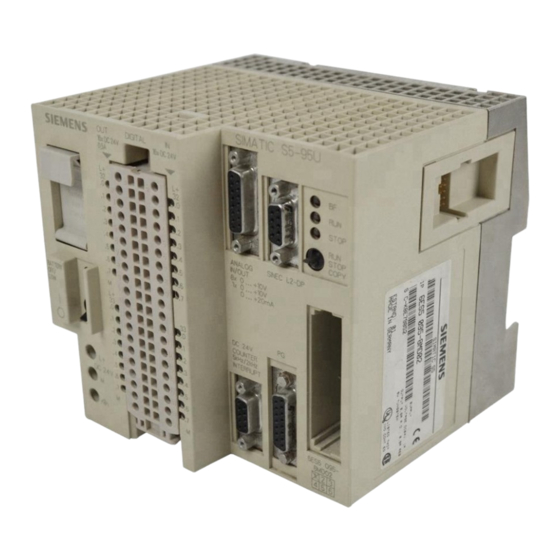
Page 26: S5-95U Programmable Controller With Dp Master Interface
System overview 1.3.2 S5-95U programmable controller with DP master interface Definition One version of the S5-95U has an integral interface for connecting the S5-95U as a DP master to the SINEC L2 DP. Mechanical design The DP master interface is integrated in the S5-95U: DP master interface Figure 1-4 S5-95U programmable controller with DP master interface... -
Page 27: 1.4 Dp Slaves In The Et 200 Distributed I/O System
S5-95U with DP slave interface IM 308-C as DP slave DP/AS-I Link Siemens or other-vendor field devices ET 200B The ET 200B is a small, compact I/O station. It is a slimline module and its degree of protection is IP 20. - Page 28 System overview ET 200U The ET 200U is a slave interface module for the I/O modules of the S5-100U. The ET 200U distributed I/O station is compatible with both SINEC L2-DP and SINEC L2- FMS. The ET 200U is eminently suitable for applications requiring a large number of locally installed inputs/outputs or modules from the S5-100U I/O range (e.g.
-
Page 29: 1.5 Sinec L2 Dp Field Bus
System overview 1.5 SINEC L2 DP field bus Definition The SINEC L2 DP field bus interconnects all stations. The physical connection to these stations is effected by means of bus connectors (exception: RS 485 repeaters and programmer interface). Characteristics The characteristics of the SINEC L2 DP field bus are as follows: reliable data transfer (hamming distance = 4, i.e. -
Page 30: 1.6 Com Et 200 Windows Parameterization Software
System overview 1.6 COM ET 200 Windows parameterization software Definition You require the COM ET 200 Windows parameterization software in order to plan the layout of the distributed I/O system and to go operational when the system is installed. Memory card for IM 308-C IM 308-C 32 K EEPROM... -
Page 31: 1.7 Memory Card And 32 K Eeprom
System overview 1.7 Memory card and 32 K EEPROM Definition IM 308-C: The memory card contains the configuration data as generated with COM ET 200 Windows and is designed for insertion in the IM 308-C master interface. S5-95U: The 32 K EEPROM contains both the configuration data as gener- ated with COM ET 200 Windows and the STEP 5 application program. -
Page 32: 1.8 Network Components
System overview 1.8 Network components Definition You require network components to connect the bus to a station, to amplify the signal and / or to convert the signal to a fiber-optic medium. Connecting the There are several ways of connecting the bus to the station: IP 20 bus connector (see Section 1.8.1) IP 66/67 bus connector, e.g. -
Page 33: Bus Connector
System overview 1.8.1 Bus connector Definition The bus connector connects the bus cable and the station. The bus connector enables you to isolate a station (under certain circumstances) without interrupting the data traffic on the bus. Mechanical design A choice of IP 20 bus connectors is available. See Table 1-4 for recommended applications. -
Page 34: Rs 485 Repeater
System overview 1.8.2 RS 485 repeater Definition An RS 485 repeater regenerates the signals on the bus. By inserting RS 485 repeaters, you can split the ET 200 distributed I/O system into a number of segments, thus bridging longer distances. Mechanical design The characteristics of the RS 485 repeaters with order numbers 6ES7 972-0AA00-0XA0 are as follows:... -
Page 35: Procedure - From Planning To Initial Operation
Procedure – from planning to initial operation In this chapter This chapter offers an overview of the procedure in the ET 200 distributed I/O system. This chapter is intended primarily for readers who as yet have no experience with the ET 200. It is in the nature of a quick reference for the rest of the manual, beginning with planning and continuing through cabling, parameterization with COM ET 200 Windows, generation of the STEP 5 application program and... -
Page 36: Planning The Layout
Procedure – from planning to initial operation Planning the layout Overview This section lists the important points for planning. Layout, planning The first thing to do when planning the layout is to draw up a site plan: Table 2-1 Planning the layout Step Objective Additional... -
Page 37: Structuring The Et 200 Distributed I/O System
Procedure – from planning to initial operation Structuring the ET 200 distributed I/O system Overview This section indicates the points that must be borne in mind with regard to the mechanical and electrical layout of the components. Setting up the To set up the ET 200 system: ET 200 system Table 2-2 Setting up the ET 200... -
Page 38: Com Et 200 Windows And Step 5 In Parallel (Im 308-C)
Procedure – from planning to initial operation What to consider before parameterization with COM ET 200 Windows Overview This section deals with the aspects you should consider before starting parameterization with COM ET 200 Windows. Considerations Broadly speaking, there are two approaches to parameterization with COM ET 200 Windows and to writing the application program: You can begin by parameterizing the configuration with COM ET 200 Windows and allow COM ET Windows to automatically... -
Page 39: Com Et 200 Windows And Step 5 In Parallel (S5-95U)
Procedure – from planning to initial operation If S5-95U is DP Before starting parameterization with COM ET 200 Windows, decide on the master following: Table 2-4 COM ET 200 Windows and STEP 5 in parallel (S5-95U) Before starting parameterization with COM ET 200 Windows, Additional decide... -
Page 40: Parameterization With Com Et 200 Windows
Procedure – from planning to initial operation Parameterization with COM ET 200 Windows Overview This section provides a brief outline of the procedure for parameterization with COM ET 200 Windows. IM 308-C as DP When you are ready to parameterize and save the configuration, proceed as master follows: Table 2-5 Parameterizing and saving the configuration (IM 308-C) -
Page 41: Parameterizing And Saving The Configuration (S5-95U)
Procedure – from planning to initial operation S5-95U as DP When you are ready to parameterize and save the configuration, proceed as master follows: Table 2-6 Parameterizing and saving the configuration (S5-95U) Step Objective Additional in- formation After starting COM ET 200 Windows, assign the parame- ters to the individual components: Sections 8.2.1 to 8.2.4... -
Page 42: Writing The Step 5 Application Program
Procedure – from planning to initial operation Writing the STEP 5 application program IM 308-C as You must know the following in order to write the STEP 5 application DP master program: Table 2-7 STEP 5 application program (IM 308-C) You must know the following in order to write the Additional information STEP 5 application program ... -
Page 43: Initial Operation Of The Et 200
Procedure – from planning to initial operation Initial operation of the ET 200 ET 200 with The procedure for initial operation of the ET 200 distributed I/O system is as IM 308-C: initial follows: operation Table 2-9 Initial operation of the ET 200 (with IM 308-C) Step Objective Additional... -
Page 44: Im 308-C Master Interface And Memory Card
IM 308-C master interface and memory card In this chapter In this chapter you will find all the information you need on: Section Topic Page Design and function of the IM 308-C Technical data of the IM 308-C How to install the IM 308-C How to install the memory card 3-10 Loading the IM 308-C operating system from memory card... -
Page 45: Function And Appearance Of The Im 308-C
IM 308-C master interface and memory card Function and appearance of the IM 308-C Purpose of the The IM 308-C enables you to connect the distributed I/O stations to the IM 308-C S5-115U, S5-135U and S5-155U programmable controllers via the SINEC L2-DP bus. -
Page 46: Controls And Features Of The Im 308-C Master Interface
IM 308-C master interface and memory card Controls and The controls and features of the master interface are as follows: features Table 3-1 Controls and features of the IM 308-C master interface Designation Function Backplane con- Backplane connectors X1 and X2 enable communication between the IM 308-C nectors X1 and X2 and the CPU via the S5 I/O bus. -
Page 47: Meanings Of "Bf" Led On The Im 308-C Master Interface
IM 308-C master interface and memory card Meaning of ”BF” The ”BF” LED indicates bus-fault messages. It can indicate the following: Table 3-2 Meanings of ”BF” LED on the IM 308-C master interface Meaning Remedy All configured slaves are – addressable Bus fault Check whether:... - Page 48 Fault in the IM 308-C or Pull and reinsert the IM 308-C. If the fault per- wrong memory card inserted sists, replace the module or contact Siemens support. Insert a memory card with the correct order number. Read the notes in Section 3.4.
-
Page 49: Technical Data Of The Im 308-C
IM 308-C master interface and memory card Technical data of the IM 308-C Block diagram Fig. 3-2 is a block diagram of the IM 308-C: Memory card Logic STOP STOP Isolation CPKLA Figure 3-2 Block diagram of the IM 308-C Technical data The table below contains the technical data of the IM 308-C. -
Page 50: Maximum Consistent Data Lengths In Bytes For Im 308-C As Dp Master
IM 308-C master interface and memory card Data consistency, The table below shows the maximum data lengths at which data consistency IM 308-C as DP is ensured. The length is automatically taken into account in parameterization master with COM ET 200 Windows. 244 bytes outputs (DP slave inputs) is the maximum if all the outputs are dig- ital with byte consistency over module. -
Page 51: Installing The Im 308-C
IM 308-C master interface and memory card Installing the IM 308-C Setting the You must set jumper X10 on the IM 308-C. Jumper X10 enables you to jumpers configure bus segments in such a way that they are not grounded: If you want to operate the SINEC L2 DP as grounded, set the jumper to position ”1–2”. -
Page 52: Slots In The S5-135U/S5-155U System
IM 308-C master interface and memory card Slots in the The tables below show you where to insert the IM 308-C in the S5-135U and S5-135U and S5-155U systems. The gray hatching indicates the slots where you can insert S5-155U the IM 308-C. -
Page 53: Installing The Memory Card
IM 308-C master interface and memory card Installing the memory card Purpose of the The memory card is used to store the following data: memory card Configuration data generated with COM ET 200 Windows, The operating system to be imported to the IM 308-C. Changing the If you want to change the memory card, proceed as follows: memory card... -
Page 54: Loading The Operating System Of The Im 308-C From The Memory Card
COM ET 200 Windows. Exception The IM 308-C release 3 is not hardware-compatible with release 2. Consequently, you must consult your Siemens contact partner regarding upgrading. You cannot upgrade to release 3 by loading the new operating system from memory card. -
Page 55: Flashing Code Output By Leds On Im 308-C When The Operating System Is
IM 308-C master interface and memory card Code for operat- Before the IM 308-C operating system is loaded from the memory card, the ing-system version four LEDs on the IM 308-C output a flashing BCD code which indicates the current statuses of the operating system on the IM 308-C and on the memory card. -
Page 56: 3.6 Im 308-C As Dp Slave
IM 308-C master interface and memory card 3.6 IM 308-C as DP slave In this section Section 3.6 summarizes everything you need to know about operating the IM 308-C as DP slave. The function of the mode selector switch and the meanings of the indicators are discussed above, in Section 3.1. -
Page 57: Maximum Consistent Data Lengths In Bytes For Im 308-C As Dp Slave
IM 308-C master interface and memory card Characteristics The characteristics of the IM 308-C as DP slave are as follows: For each IM 308-C as DP slave, the DP master can process up to 122 bytes inputs (DP slave outputs) and up to 244 bytes outputs (DP slave inputs). -
Page 58: Structure Of Device-Specific Diagnostics Of The Im 308-C As Dp Slave
IM 308-C master interface and memory card Restrictions You need a memory card in order to operate the IM 308-C as DP slave, so the following restrictions apply: The station number of the IM 308-C as DP slave is set by means of the memory card. -
Page 59: Design And Method Of Operation Of The S5-95U With Dp Master Interface
Design and method of operation of the S5-95U with DP master interface In this chapter This chapter contains information on: Section Topic Page Design of the S5-95U Pin assignment of the DP master interface Data exchange between S5-95U and DP slaves Technical data of the S5-95U Installing S5-95U and 32 K EEPROM 4-10... -
Page 60: Design Of The S5-95U
Design and method of operation of the S5-95U with DP master interface Design of the S5-95U Front view of the This is a front view of the S5-95U, showing all the indicators, controls and S5-95U interfaces. Figure 4-1 Front view of the S5-95U with DP master interface Indicators, The table below explains the indicators, controls and interfaces of the controls... - Page 61 Design and method of operation of the S5-95U with DP master interface Table 4-1 The indicators, controls and interfaces of the S5-95U, continued Callout Designation Purpose in Fig. LEDs for digital LED lights up when the signal state of the digital input/output is ”1”. inputs/ outputs Terminals for...
-
Page 62: Significance Of The "Bf", "Run" And "Stop" Leds Of The S5-95U
Design and method of operation of the S5-95U with DP master interface Significance of the The significance of the ”BF”, ”RUN” and ”STOP” LEDs is as follows: LEDs Table 4-2 Significance of the ”BF”, ”RUN” and ”STOP” LEDs of the S5-95U STOP Meaning Remedy... -
Page 63: Pin Assignment Of The Dp Master Interface
Design and method of operation of the S5-95U with DP master interface Pin assignment of the DP master interface Purpose of the The DP master interface enables you to connect distributed I/Os to the interface S5-95U via the SINEC L2 DP bus. Assignment The DP master interface is a 9-way D-Sub port in compliance with the PROFIBUS-DP draft standard. -
Page 64: Exchange Of Data Between S5-95U And Dp Slaves
Design and method of operation of the S5-95U with DP master interface Exchange of data between S5-95U and DP slaves Exchange of data The S5-95U and the DP slaves exchange data through the agency of the control and communication processors in the S5-95U. The link to SINEC L2 DP is established via the DP master interface. -
Page 65: Et 200 Distributed I/O System Ewa 4Neb 780 6000-02A
Design and method of operation of the S5-95U with DP master interface Operating This illustration shows the principle of data exchange as implemented in the principle S5-95U. DP master: S5-95U DP slave: e. g. ET 200B Control Communication processor processor Application program Address spaces: Send buffer... -
Page 66: Technical Data Of The S5-95U
Design and method of operation of the S5-95U with DP master interface Technical data of the S5-95U Technical data The technical data of the S5-95U with DP master interface is listed in the table below. General technical data applicable to all versions of the S5-95U is to be found in the system manual S5-90U/S5-95U Programmable Controller. - Page 67 Design and method of operation of the S5-95U with DP master interface Table 4-4 Technical data of the S5-95U with DP master interface, continued Technical data Special SINEC L2 DP data Number of S5-95Us as DP max. 124 DP masters masters on the SINEC L2 DP Number of DP slaves per S5-95U max.
-
Page 68: Installing S5-95U And 32 K Eeprom
Design and method of operation of the S5-95U with DP master interface Installing S5-95U and 32 K EEPROM Installing S5-95U You install the S5-95U with DP master interface in just the same way as any other S5-95U version. The installation procedure for the S5-95U is described in detail in the system manual S5-90U/S5-95U Programmable Controller, Chapter 3. - Page 69 Routing cables; connecting and installing bus connectors In this chapter This chapter contains information on: Section Topic Page Notes on routing cables Mechanical design and applications of bus connectors 5-15 Connecting bus cables to bus connectors 5-18 Connecting bus connectors to modules 5-25 Goal This chapter contains all the information that you must bear in mind with...
-
Page 70: 5.1 Notes On Routing Cables
Routing cables; connecting and installing bus connectors 5.1 Notes on routing cables Overview Certain rules and regulations apply to use of the ET 200 as a component in a higher-order system. These rules and regulations vary from application to application. In this chapter The various sections of this chapter contain information on the following topics:... -
Page 71: General Rules And Regulations For Operation Of Et 200
Routing cables; connecting and installing bus connectors 5.1.1 General rules and regulations for operation of ET 200 Specific The rules and regulations for safety at work and accident prevention (e.g. application machine-protection guidelines) must be observed in all instances. EMERGENCY OFF IEC 204 EMERGENCY-OFF facilities must remain effective in all operating facilities modes of the plant or system. - Page 72 Routing cables; connecting and installing bus connectors 24 V DC supply The points to bear in mind with regard to the 24 V supply are as follows: With regard to ... it is important to ensure ... provide adequate Buildings exterior lightning lightning protection protection...
-
Page 73: In-Building Cable Routing
Routing cables; connecting and installing bus connectors 5.1.2 In-building cable routing Introductory The EMC rules with regard to in-building cable routing (inside and outside remarks cabinets) require certain clearances to be maintained between individual line groups. Table 5-1 shows the general rules with regard to spacing as they apply to cable selection. - Page 74 Routing cables; connecting and installing bus connectors Table 5-1 In-building cable routing, continued Cables for ... and cables for ... route ... DC voltage Bus signals, shielded in separate bundles or cable ducts ( 60 V and 400 V), (SINEC L1, SINEC L2) (no minimum spacing necessary) unshielded Data signals, shielded...
-
Page 75: Outdoor Cable Routing
Appendix D contains additional information on lightning protection for the information ET 200 distributed I/O system. If you have any questions, do not hesitate to contact your local Siemens branch or a company specializing in lightning protection. ET 200 Distributed I/O System... -
Page 76: Potential Equalization
Routing cables; connecting and installing bus connectors 5.1.4 Potential equalization When do differ- Differences in potential can occur, for example, when different mains ences in potential supplies are used. Under these circumstances, potential differences may occur? occur between the various parts of a system, if programmable controllers and inputs/outputs are connected by potential-bonded couplings, cable shields are connected at both ends and grounded to different parts of... -
Page 77: Cable Shielding
Routing cables; connecting and installing bus connectors 5.1.5 Cable shielding Definition Shielding is a means of weakening (attenuating) magnetic, electric and electromagnetic interference fields. Interference currents on cable shields are diverted to ground via the shield busbar, which forms a conductive connection with the housing. It is particularly important to ensure a low-ohmic connection to the protective conductor, as otherwise the interference currents themselves may become a source of interference. -
Page 78: Securing Shielded Cables With Cable Clamps And Cable Ties
Routing cables; connecting and installing bus connectors Correct shield Observe the following points: installation Use cable clamps made of metal to secure the braided shield. The enclosing clamps must hold a large part of the shield and make good contact (see Fig. 5-1). Connect the shield to a shield busbar immediately adjacent to the point where the cable enters the cabinet. -
Page 79: Measures To Prevent Interference Voltages
Routing cables; connecting and installing bus connectors 5.1.6 Measures to prevent interference voltages Overview Frequently, measures designed to suppress interference voltages are not adopted until the controller is in operation and reception of a traffic signal is found to be unsatisfactory. The outlay for post-installation measures (e.g. special contactors) can often be reduced to a significant extent if you observe the following points when configuring your control system. - Page 80 Routing cables; connecting and installing bus connectors Installation and When the devices are installed, it is important to ensure that the inactive grounding of metal components are correctly grounded with connectors having large inactive metal contact areas. Correct grounding establishes a uniform reference potential for components the control system and reduces the effects on spurious interference.
-
Page 81: Special Measures For Interference-Proof Operation
Routing cables; connecting and installing bus connectors 5.1.7 Special measures for interference-proof operation Commutating As a rule, the inductors driven by SIMATIC S5 (e.g. contactor/relay coils) do capacitors for not require external commutating capacitors, because the requisite inductors components are integrated in the modules. -
Page 82: Measures For Suppressing Interference From Fluorescent Tubes In Cabinets
Routing cables; connecting and installing bus connectors Circuit with A circuit incorporating a varistor has the following properties: varistor The amplitude of the shutdown overvoltage is limited, but the overvoltage is not suppressed Overvoltage slope is uniform Shutdown delay is slight Circuit with RC A circuit incorporating an RC element has the following properties: element... -
Page 83: 5.2 Bus Connector: Mechanical Design And Applications
Routing cables; connecting and installing bus connectors 5.2 Bus connector: mechanical design and applications Application You need bus connectors to connect the SINEC L2 DP bus to a station. There is a choice of IP 20 bus connectors; the uses of the various types are shown in Table 5-2. -
Page 84: Bus Connector With Order Number 6Es5
Routing cables; connecting and installing bus connectors Mechanical design The bus connector with the order number 6ES5 ... is illustrated below: (6ES5 ...) Screw for 9-pin sub-D male adapter for securing to connection to station station Switch for terminating resistor Prog. -
Page 85: Bus Connector With Order Number 6Es7 972-0B.20
Routing cables; connecting and installing bus connectors Mechanical design The bus connector with the order number 6ES7 972-0B.20... is illustrated (6ES7 972-0B.20 below: ...) Screws for se- 9-pin sub-D male curing to station adapter for connection to station Switch for terminating resistor Housing screw Prog. -
Page 86: 5.3 Connecting The Bus Cable To The Bus Connector
Routing cables; connecting and installing bus connectors 5.3 Connecting the bus cable to the bus connector Properties of the Use a two-conductor, twisted and shielded cable with the following bus cable properties: Table 5-4 Properties of the SINEC L2 bus cable Features Values approx. -
Page 87: Permissible Cable Lengths For A Segment Using Rs 485 Repeaters With Order Number 6Es7 972-0Aa00-0Xa0
Routing cables; connecting and installing bus connectors Maximum cable The maximum cable lengths as stated in the table below are guaranteed only length for SINEC L2 bus cables. Table 5-6 Permissible cable lengths for a segment using RS 485 repeaters with order number 6ES7 972-0AA00-0XA0 Baud rate Maximum cable... -
Page 88: Connecting Bus Cable To Bus Connectors With Order Number 6Es5
Routing cables; connecting and installing bus connectors 5.3.1 Connecting bus cable to bus connectors with order number 6ES5 ... Preparing the bus To connect the bus cable to a bus connector with order number 6ES5 ..., cable proceed as follows: 1. -
Page 89: Connecting Bus Cable To Bus Connector (6Es5 ...)
Routing cables; connecting and installing bus connectors 1. Connect the bus cable as shown in Figs. 5-9 and 5-10 by connecting the same cores to terminal A or B (e.g. always connect green conductor to terminal A and red conductor to terminal B). Bus-cable connection for first Bus-cable connection for all and last stations on the bus... -
Page 90: Connecting Bus Cable (6Es7 972-0B.10
Routing cables; connecting and installing bus connectors 5.3.2 Connecting bus cable (6ES7 972-0B.10 ...) to bus connectors Preparing the bus To connect the bus cable to a bus connector with order number cable 6ES7 972-0B.10 ..., proceed as follows: 1. Strip the ends of the cable conductors as shown in Fig. 5-11. 6XV1 830–0AH10/-3BH10 6XV1 830–3AH10 Figure 5-11 Stripping cables for connection to bus connector (6ES7 972-0B.10 ...) -
Page 91: Connecting Bus Cable To Bus Connectors With Order Number 6Es7 972-0B.20
Routing cables; connecting and installing bus connectors 5.3.3 Connecting bus cable to bus connectors with order number 6ES7 972-0B.20 ... Preparing the bus To connect the bus cable to a bus connector with order number cable 6ES7 972-0B.20 ..., proceed as follows: 1. -
Page 92: Connecting Bus Cable To Bus Connector (6Es7 972-0B.20 ...)
Routing cables; connecting and installing bus connectors 4. The bus connector with order number 6ES7 972-0B.20 is supplied with the latching element set to the offset position. If you want a right-angle cable output – slacken the left screw in the latching element, –... -
Page 93: 5.4 Connecting The Bus Connector To The Module
Routing cables; connecting and installing bus connectors 5.4 Connecting the bus connector to the module Connecting the The procedure for connecting the bus connector is as follows: bus connector 1. Push the bus connector into position on the module adapter. 2. -
Page 94: Rs 485 Repeaters: Installing, Connecting And Operating
RS 485 repeaters: installing, connecting and operating In this chapter This chapter contains information on: Section Topic Page Scope of application of the RS 485 repeater Mechnical design of the RS 485 repeater (6ES7 972-0AA00-0XA0) Configuration options with the RS 485 repeater Installing and removing the RS 485 repeater Grounded/non-grounded operation of the RS 485 repeater 6-10... -
Page 95: The Rs 485 Repeater: Scope Of Application
RS 485 repeaters: installing, connecting and operating The RS 485 repeater: scope of application What is an RS 485 An RS 485 repeater amplifies data signals on bus lines and is the link repeater? between individual bus segments. Using the RS 485 You must use an RS 485 repeater, if: repeater you want to connect more than 32 stations to the bus,... -
Page 96: Mechanical Design Of The Rs 485 Repeater With Order Number
3 Mbaud 93.75 kbaud 6 Mbaud 187.5 kbaud 12 Mbaud SIEMENS RS 485 REPEATER RS 485-REPEATER Terminating resistor for bus segment 2 Terminals for bus cable of bus segment 2 Clamp for securing the RS 485 repeater to standard-section busbar... -
Page 97: Technical Data Of The Rs 485 Repeater
RS 485 repeaters: installing, connecting and operating Technical data The table below shows the technical data of the RS 485 repeater: Table 6-4 Technical data of the RS 485 repeater Technical data Power supply Rated voltage 24 V DC Ripple 18 V DC to 30 V DC Current consumption at rated voltage No consumer via PG/OP interface... -
Page 98: Block Diagram Of The Rs 485 Repeater
RS 485 repeaters: installing, connecting and operating Pin assignment of The pin assignment of the 9-pin sub-D adapter is as follows: the sub-D adapter (PG/OP interface) Table 6-5 Pin assignment of the 9-pin sub-D adapter (PG/OP interface) View Pin No. Signal Designation –... -
Page 99: Configuration Options With The Rs 485 Repeater
RS 485 repeaters: installing, connecting and operating Configuration options with the RS 485 repeater Overview This section discusses the configuration options offered by the RS 485 repeater: Segment 1 and segment 2 terminating at the RS 485 repeater Segment 1 terminating at the RS 485 repeater and segment 2 looped through the RS 485 repeater, Segment 1 and segment 2 looped through the RS 485 repeater. -
Page 100: Two Bus Segments Connected To The Rs 485 Repeater
RS 485 repeaters: installing, connecting and operating Segment 1 In Fig. 6-4, one of the two segments connected to the RS 485 repeater is terminated, looped through and one is terminated: segment 2 looped through Segment 1 Segment 1 Terminating resistor bus segment 1 bus segment bus segment 1... -
Page 101: Installing And Removing The Rs 485 Repeater
RS 485 repeaters: installing, connecting and operating Installing and removing the RS 485 repeater Overview You can install the RS 485 repeater: on a special busbar for S7-300 on a standard-section busbar (order number 6ES5 710-8MA..) Installation on If you want to mount the RS 485 repeater on a special busbar for S7-300, you busbar for S7-300 must first remove the clamp at the rear of the RS 485 repeater (see Fig. -
Page 102: Removing The Rs 485 Repeater From The Busbar For S7-300
RS 485 repeaters: installing, connecting and operating Releasing from To release the RS 485 repeater from a busbar for S7-300: busbar for S7-300 1. Release the screw securing the RS 485 repeater (1) and 2. swing the RS 485 repeater up and away from the busbar (2). Figure 6-7 Removing the RS 485 repeater from the busbar for S7-300 Installation on... -
Page 103: Grounded/Non-Grounded Operation Of The Rs 485 Repeater
RS 485 repeaters: installing, connecting and operating Grounded/non-grounded operation of the RS 485 repeater Grounded Grounded operation means that ground and PE are interconnected. operation The RS 485 repeater is supplied with a jumper inserted between ”M” and ”PE” (see Fig. 6-9). If the jumper is not inserted between ”M” and ”PE”, you must establish a conductive connection between ”M”... -
Page 104: Connecting The Voltage Supply
RS 485 repeaters: installing, connecting and operating Connecting the voltage supply Cable type For the 24 V DC voltage supply, use flexible cables with a cross-section from 0.25 mm to 2.5 mm (AWG 26 to 14). Rules for routing See Section 5.1 for details on cable routing (DC voltage 60 V, unshielded). -
Page 105: Connecting The Bus Cable
RS 485 repeaters: installing, connecting and operating Connecting the bus cable Cable type The SINEC L2 bus cable must satisfy the requirements laid down in Section 5.3. Connecting the Connect the SINEC L2 bus cable to the RS 485 repeater as follows: SINEC L2 bus 1. -
Page 106: Starting Com Et 200 Windows
Starting COM ET 200 Windows In this chapter This chapter contains information on: Section Topic Page Scope of applications and preconditions for using the COM ET 200 Windows parameterization software Starting COM ET 200 Windows Graphical user interface of COM ET 200 Windows Example of how to parameterize a configuration with COM ET 200 Windows Goal... -
Page 107: Adapters For Com Et 200 Windows
Starting COM ET 200 Windows Scope of application and preconditions for using the COM ET 200 Windows parameterization software Why you need You need the COM ET 200 Windows parameterization software: COM ET 200 to configure the bus structure, the hosts, the DP masters and DP slaves; Windows to read the data from a memory card or write data to a memory card, and to generate detailed system documentation. - Page 108 Starting COM ET 200 Windows Starting COM ET 200 Windows Making a backup Before you install COM ET 200 Windows, you should use MS-DOS or the copy File Manager under MS-Windows to create a backup copy of the system disks: Thereafter, you use only the backup copy.
-
Page 109: Graphical User Interface Of Com Et 200 Windows
Starting COM ET 200 Windows Graphical user interface of COM ET 200 Windows Overview The COM ET 200 Windows GUI incorporates the following standard elements familiar from MS-Windows: COM ET 200 Title bar File Edit Configure Documentation Service Window ? Menu bar Å... -
Page 110: The Functions In The Pull-Down Menus
Starting COM ET 200 Windows Menu bar The menu bar contains the names of the various pull-down menus. By opening a pull-down menu, you can call certain functions. Table 7-2 The functions in the pull-down menus Menu Commands in menu File Open, save and close program files Read master systems from and save to memory card, DP master... -
Page 111: Application Window
Starting COM ET 200 Windows Application Working in an application window, you construct the bus by dragging and window dropping icons. Each application window contains a DP master to which you assign DP slaves by adding icons. By double-clicking on the icon or designation, you automatically switch to the dialog box for entering the individual parameters. -
Page 112: Parameterization With Com Et 200 Windows, A Worked Example
Starting COM ET 200 Windows Parameterization with COM ET 200 Windows, a worked example Overview This section contains a small example showing how to parameterize a configuration with COM ET 200 Windows. Start COM ET 200 Windows Enter the bus parameters Enter the host parameters Enter the master parameters Enter the slave parameters for the ET 200B and ET 200U... -
Page 113: Example Of The "Master Host Selection" Window
Starting COM ET 200 Windows Starting To work with COM ET 200 Windows: COM ET 200 1. Start MS-Windows and Windows 2. double-click on the icon for COM ET 200 Windows. Result: COM ET 200 Windows starts. 3. Select File New and 4. -
Page 114: Entering Bus Parameters
Starting COM ET 200 Windows Entering bus To enter the parameters for the bus: parameters 1. In the application window, double-click on ”Bus designation”. Result: The ”Bus parameters” dialog box is opened. Bus parameters Bus example for parameterization Bus designation: Parameters Bus profile: PROFIBUS-DP... -
Page 115: Example Of The "Master Parameters" Dialog Box
Starting COM ET 200 Windows Entering master To enter the parameters for the master: parameters 1. In the application window, double-click on the icon for the programmable controller. Result: The ”Master parameters” dialog box is opened. Master parameters Station number: Cancel Station type: IM 308-C... -
Page 116: Example Of The "Slave Parameters Et 200B" Dialog Box
Starting COM ET 200 Windows Entering slave To configure the ET 200B distributed I/O station: parameters for 1. In the ”Slaves” window, click on the icon for ET 200 and by holding ET 200B down the left mouse button, drag it to the bottom of the bus. Result: A selection list allowing you to choose the station number of the slave is opened. - Page 117 Starting COM ET 200 Windows 3. Select the ET 200U with order number 6ES5 318-8MB12 as the station type and click on the ”Configure ...” button to switch to the ”Configure” dialog box. Result: The ”Configure ET 200U” dialog box is opened. Configure: ET 200U Order number Comment...
- Page 118 Starting COM ET 200 Windows Saving the file It is now time to save the data with COM ET 200 Windows. 1. Save the entire configuration in a program file by selecting File Save as. 2. Enter a file name and confirm by pressing the ”OK” button. Printing the You can print documents that will show you, for example, which STEP 5 system...
-
Page 119: Parameterizing, Saving And Documenting The Configuration With Com Et 200 Windows
Parameterizing, saving and documenting the configuration with COM ET 200 Windows In this chapter This chapter contains information on: Section Topic Page Creating and opening a program file; importing data Parameterizing an ET 200 distributed I/O system with COM ET 200 Windows Opening, reading and editing type files 8-22 Saving the configuration parameterized with COM ET 200 Win-... -
Page 120: File Types In Com Et 200 Windows
Parameterizing, saving and documenting the configuration with COM ET 200 Windows 8.1 Creating and opening a program file; importing data Definitions COM ET 200 Windows recognizes files of different types: Table 8-1 File types in COM ET 200 Windows Name Meaning Exten sion... - Page 121 Parameterizing, saving and documenting the configuration with COM ET 200 Windows Creating a file You create a new program file when you 1. Start COM ET 200 Windows and 2. in COM ET 200 Windows, select File New. 3. Enter the parameters in the Master host selection dialog box and 4.
- Page 122 Parameterizing, saving and documenting the configuration with COM ET 200 Windows Importing data You need the ”Import data from binary file” function only if the original from a binary file program file is lost. To import data from a binary file: 1.
-
Page 123: Parameterizing An Et 200 Distributed I/O System With Com Et 200 Windows
Parameterizing, saving and documenting the configuration with COM ET 200 Windows 8.2 Parameterizing an ET 200 distributed I/O system with COM ET 200 Windows In this section Section 8.1 contains information on: Section Topic Page 8.2.1 Entering bus parameters 8.2.2 Entering host parameters 8.2.3 Entering master parameters... -
Page 124: Application Window
Parameterizing, saving and documenting the configuration with COM ET 200 Windows Building the Build your ET 200 configuration in the application window: ET 200 1. Begin by entering the parameters for the bus, the host and the DP master. configuration See Sections 8.2.1 through 8.2.3 for details. -
Page 125: Meanings Of Bus Parameters
Parameterizing, saving and documenting the configuration with COM ET 200 Windows 8.2.1 Entering bus parameters Definition You use the bus parameters to define: the designation for the bus system the bus profile for transmitting data on the bus the baud rate whether the bus incorporates an RS 485 repeater, and the duration of the response monitoring time. -
Page 126: Bus Times That Must Be Set For A User-Defined Bus Profile
Parameterizing, saving and documenting the configuration with COM ET 200 Windows Entering bus To enter the bus parameters: parameters 1. Select Configure Bus parameters double-click on ”Bus designation”. Result: The ”Bus parameters” dialog box is opened. 2. Set the bus parameters. Click on ”Help” for more information. 3. -
Page 127: Entering Host Parameters
Parameterizing, saving and documenting the configuration with COM ET 200 Windows 8.2.2 Entering host parameters Definition A host is a system or device containing one or more DP masters. IM 308–C The S5-115U, S5-135U and S5-155U programmable controllers can be hosts for the IM 308-C DP master. -
Page 128: Meanings Of Host Parameters
Parameterizing, saving and documenting the configuration with COM ET 200 Windows Meanings of the The meanings of the individual host parameters are shown in Table 8-4. host parameters Table 8-4 Meanings of host parameters Designation Meaning Default Host designation The name for the host system. Max. length: 40 characters. –... -
Page 129: Entering Master Parameters
Parameterizing, saving and documenting the configuration with COM ET 200 Windows 8.2.3 Entering master parameters IM 308-C By setting master parameters for the IM 308-C, you define: the designation of the IM 308-C the host to which the IM 308-C is assigned how the distributed I/O is addressed whether the IM 308-C is addressed by the CPU in multiprocessor mode which error messages will be generated (QVZ or PEU and response moni-... - Page 130 Parameterizing, saving and documenting the configuration with COM ET 200 Windows Table 8-5 Meanings of the master parameters (IM 308-C), continued Designation Meaning Default Addressing If you have not yet assigned addresses to the DP slaves, you have the choice of: Linear linear addressing P-page addressing, or...
- Page 131 Parameterizing, saving and documenting the configuration with COM ET 200 Windows Table 8-5 Meanings of the master parameters (IM 308-C), continued Designation Meaning Default Response Response monitoring enables you to define how the DP slave reacts to a DP master monitoring for error or a break in the data traffic on the bus.
-
Page 132: Entering Slave Parameters
Parameterizing, saving and documenting the configuration with COM ET 200 Windows 8.2.4 Entering slave parameters Definition The slave parameters enable you to define: the family and type of the slave the name of the slave the configuration and corresponding addresses of the slave (Configure ...) the structure of a parameterization telegram, if necessary (Parameterize ...), and whether or not the error-reporting mode selected for the DP master or... - Page 133 Parameterizing, saving and documenting the configuration with COM ET 200 Windows Table 8-6 Meanings of the slave parameters Designation Meaning Default Station number The station number is a bus-wide unique number for the DP slave. (assigned station 1 to 123 for linear addressing number) 1 to 119 for P-page addressing 1 to 107 for Q-page addressing...
- Page 134 Parameterizing, saving and documenting the configuration with COM ET 200 Windows Entering slave To enter slave parameters for a new DP slave, parameters via 1. Select Configure Slave parameters and menu bar 2. confirm the desired slave station number by pressing the ”OK” button. Result: The ”Slave parameters”...
-
Page 135: Creating A New Master System
Parameterizing, saving and documenting the configuration with COM ET 200 Windows 8.2.5 Creating a new master system Definition Each DP master plus the DP slaves assigned to it constitutes a master system. You have to create a new master system if you have at least two DP masters connected to a physical bus. -
Page 136: Configuring Im 308-C As Dp Slave
Parameterizing, saving and documenting the configuration with COM ET 200 Windows 8.2.6 Configuring IM 308-C as DP slave Definition As of release 3, the IM 308-C can be operated as: DP master DP slave or as DP master and DP slave (see Section 3.6). Procedure The procedure for configuring an IM 308-C as DP slave is as follows: 1. -
Page 137: Assigning A Shared-Input Master (Im 308-C Only)
Parameterizing, saving and documenting the configuration with COM ET 200 Windows 8.2.7 Assigning a shared-input master (IM 308-C only) Definition In addition to the parameterization master, other DP masters can be granted read access to each DP slave with inputs. These DP masters are known as shared-input masters. -
Page 138: Making Provision For Other-Vendor Masters
Parameterizing, saving and documenting the configuration with COM ET 200 Windows 8.2.8 Making provision for other-vendor masters Definition If the bus includes masters other than those entered with COM ET 200 Windows, you must make provision for these other-vendor masters in the target rotation time. Making provision To make provision for other-vendor masters in the target rotation time: for other-vendor... -
Page 139: Assigning Dp Slaves To Groups
Parameterizing, saving and documenting the configuration with COM ET 200 Windows 8.2.9 Assigning DP slaves to groups Definition If you want to send the FREEZE or SYNC control commands to DP slaves in the FB IM308C, you must arrange the DP slaves in groups. Each group consists of at least one DP slave. -
Page 140: Opening, Reading And Editing Type Files
The manufacturers supply the type files for non-Siemens devices. If you do not receive a type file for a non-Siemens slave which functions in the same way as a DP standard slave, you can generate a type file yourself with the aid of COM ET 200 Windows. - Page 141 There is a type file for each station type in the family of SIEMENS DP slaves: these files are supplied with COM ET 200 Windows or are available on request. To edit a new type file: 1.
-
Page 142: Saving The Configuration Parameterized With Com Et 200 Windows
Parameterizing, saving and documenting the configuration with COM ET 200 Windows 8.4 Saving the configuration parameterized with COM ET 200 Windows Options for saving You have several options for saving the configuration parameterized with COM ET 200 Windows. Table 8-7 Saving the configuration parameterized with COM ET 200 Windows If you ... -
Page 143: Save To Memory Card (Im 308-C)
Parameterizing, saving and documenting the configuration with COM ET 200 Windows 8.4.1 Save to memory card (IM 308-C) Preconditions for To export data to a memory card, use of memory the PG must have a memory card interface, or cards your PG must have an E(E)PROM slot with the appropriate programming adapter, or your PC must have an external programming unit. -
Page 144: Save To 32 K Eeprom (In S5-95U)
Parameterizing, saving and documenting the configuration with COM ET 200 Windows 8.4.2 Save to 32 K EEPROM (in S5-95U) 32 K EEPROM for If you have the S5-95U as DP master, you use a special memory module, an S5-95U EEPROM with a capacity of 32 Kbytes, supplied with the S5-95U with DP master interface. - Page 145 Parameterizing, saving and documenting the configuration with COM ET 200 Windows 3. Enter the current station number of the DP master (default after reset = STN1). The current station number is available as a hexadecimal value in EB 62. Result: The S5-95U goes to STOP, regardless of whether the mode selec- tor switch is set to STOP or RUN.
-
Page 146: Documenting The Configuration
Parameterizing, saving and documenting the configuration with COM ET 200 Windows 8.5 Documenting the configuration Overview COM ET 200 Windows can generate the following lists to document the con- figuration: Table 8-9 Documenting the configuration Documentation ... Contains ... List of all bus parameters ... -
Page 147: Printing With Com Et 200 Windows
Parameterizing, saving and documenting the configuration with COM ET 200 Windows 8.6 Printing with COM ET 200 Windows What can I print? You can print all the lists that are named in the ”Documentation” list box. How do I print? To print a list: 1. -
Page 148: Im 308-C – Addressing, Diagnostics And Use Of The Fb Im 308-C
IM 308-C – addressing, diagnostics and use of the FB IM308C In this chapter This chapter contains information on: Section Topic Page Addressing Diagnostics with STEP 5 9-12 Reading master diagnostics 9-13 Reading slave diagnostics 9-15 Sending the FREEZE and SYNC control commands 9-21 Assigning station numbers 9-22... -
Page 149: Addressing
IM 308-C – addressing, diagnostics and use of the FB IM308C 9.1 Addressing In this Section Section 9.1 contains information on the following: Section Topic Page 9.1.1 Linear addressing 9.1.2 Page addressing 9.1.3 Addressing via the FB IM308C function block 9-10 9.1.4 Access commands for distributed I/O... - Page 150 IM 308-C – addressing, diagnostics and use of the FB IM308C Address space By default, the IM 308-C uses the address space (F)F800 to (F)F9FF used addressing the distributed I/O. This address space is also required if you use only linear or page addressing. Caution Danger of double addressing The IM 308-C uses fully one or more of the address areas shown in Table...
-
Page 151: Modes Of Addressing With The Im 308-C As Dp Master
IM 308-C – addressing, diagnostics and use of the FB IM308C Options for Your options for addressing the distributed I/O system are as follows: addressing linear addressing (P and Q areas) page addressing (P and Q areas) function block FB IM308C (FB 192). Table 9-1 shows the inputs and outputs at your disposal and the applicable modes of addressing. -
Page 152: Linear Addressing
IM 308-C – addressing, diagnostics and use of the FB IM308C 9.1.1 Linear addressing Definition Linear addressing is possible in the P and Q areas of the CPU. Each input or output of a DP slave has one and only one address in the P or Q area, respectively (i.e. - Page 153 IM 308-C – addressing, diagnostics and use of the FB IM308C When should I use Use linear addressing when you do not need more than 512 bytes for inputs linear addressing? and 512 bytes for outputs as the sum of all DP slaves in a host. If you require more input or output bytes, use P-page addressing, Q-page addressing or the FB IM308C.
-
Page 154: Page Addressing
IM 308-C – addressing, diagnostics and use of the FB IM308C 9.1.2 Page addressing Definition of page In page addressing, 16 pages numbered from n to (n + 15) are created on addressing each IM 308-C. The first page number n corresponds to the number of the IM 308-C. -
Page 155: How Page Addressing Works
IM 308-C – addressing, diagnostics and use of the FB IM308C Example: page The table below shows how page addressing works. Note that the mode addressing shown here by way of example illustrates P-page addressing. In the example, the I/O byte PY 193 is read from the page having the page number 18. - Page 156 IM 308-C – addressing, diagnostics and use of the FB IM308C Using the Q area You can use I/O bytes QB 0 to QB 254 for the I/O modules in the expansion unit and for distributed I/O. Warning There is a possibility of inputs or outputs receiving double assignments in the Q area.
-
Page 157: Addressing Via The Fb Im308C Function Block
IM 308-C – addressing, diagnostics and use of the FB IM308C 9.1.3 Addressing via the FB IM308C function block Definition If you opt for addressing through the FB IM308C (FB 192) you use the CP page area and the IM3/IM4 area to address the distributed inputs and outputs. -
Page 158: Access Commands For Distributed I/O
IM 308-C – addressing, diagnostics and use of the FB IM308C 9.1.4 Access commands for distributed I/O Overview You can access the addresses of the distributed I/O as follows: Via the process image or with load/transfer commands Via the standard function block FB IM308C Process image or You cannot access inputs or outputs via the process image or load/transfer load/transfer com-... -
Page 159: Diagnostics With Step 5
IM 308-C – addressing, diagnostics and use of the FB IM308C 9.2 Diagnostics with STEP 5 Overview Diagnostics means identifying and pinpointing errors. You require the FB IM308C function block to read the diagnostic data. Structure of Diagnostics consists of master diagnostics and slave diagnostics. diagnostics Master diagnostics comprises the diagnostic functions implemented in the DP master for the DP slaves of the master, and for the status of the DP... -
Page 160: Reading Master Diagnostics
IM 308-C – addressing, diagnostics and use of the FB IM308C 9.3 Reading master diagnostics Definition Master diagnostics consists of 64 bytes structured as follows: Overview diagnostics (16 bytes) In overview diagnostics, you can check all DP slaves for which diagnostic data is available. -
Page 161: Appearance Of Master Diagnostics
IM 308-C – addressing, diagnostics and use of the FB IM308C Structure of This table shows how master diagnostics is structured: master diagnostics Table 9-5 Appearance of master diagnostics Diagnostics Byte Bit (corresponds to the DP slave with the station number:) Data format rec format rec. -
Page 162: Reading Slave Diagnostics
IM 308-C – addressing, diagnostics and use of the FB IM308C 9.4 Reading slave diagnostics Definition Slave diagnostics comprises a maximum of 40 bytes and is structured as follows: Station status 1 through 3 (length: 3 bytes) Station status 1 through 3 reflects the status of a DP slave. Master-station number (length: 1 byte) The master-station number diagnostic byte contains the station number of the DP master which parameterized the DP slave. - Page 163 IM 308-C – addressing, diagnostics and use of the FB IM308C Diagnostics of With the exception of the diagnostics messages listed below, shared-input shared-input slave diagnostics can be analyzed only by the parameterization master: slaves The following diagnostics messages are updated cyclically by the shared- input master: Overview diagnostics (station powerfail only) Data transfer list...
-
Page 164: Structure Of Slave Diagnostics
IM 308-C – addressing, diagnostics and use of the FB IM308C Structure of slave Slave diagnostics is structured as follows: diagnostics Table 9-6 Structure of slave diagnostics Byte Meaning Recommended data format Station status 1 Station status 2 Station status 3 Master-station number Manufacturer ID (high byte) Manufacturer ID (low byte) -
Page 165: Structure Of Station Status 2
ID manufacturer ID consists of two bytes. Slave diagnostics; This part of slave diagnostics depends on whether the DP slave is a DP stan- continued dard slave or is in compliance with the DP Siemens standard: Section Topic Page 9.4.1... -
Page 166: Slave Diagnostics For Dp Standard Slaves
IM 308-C – addressing, diagnostics and use of the FB IM308C 9.4.1 Slave diagnostics for DP standard slaves Overview On the IM 308-C master interface, the diagnostic functions are stored in accordance with draft standard DIN 19245, Part 3. The slave diagnostic functionality is stored separately for slaves that do not comply with DIN 19245, Part 3 (see Section 9.4.2). -
Page 167: Slave-Specific Diagnostics For Dp Siemens Slaves
9.4.2 Slave-specific diagnostics for DP Siemens slaves. Structure The structure of the slave diagnostics for DP Siemens slaves varies from slave to slave: Table 9-11 Structure of the slave-specific diagnostics for DP Siemens slaves Byte ET 200B (6ES5 ...) ET 200C (6ES5 ...) ET 200U (6ES5 ...) -
Page 168: Sending The Freeze And Sync Control Commands
IM 308-C – addressing, diagnostics and use of the FB IM308C 9.5 Sending the FREEZE and SYNC control commands What is a control The IM 308-C can send simultaneous commands to a group of DP slaves in command? order to synchronize them. The FREEZE and SYNC control commands enable you to synchronize groups of DP slaves in response to events. -
Page 169: Assigning Station Numbers
No application DP slaves whose station number can only be set by means of switches set in the housing, or DP Siemens slaves: you cannot assign the station numbers by means of the software. Assigning station To assign a station number to a DP slave, proceed as follows: numbers 1. - Page 170 IM 308-C – addressing, diagnostics and use of the FB IM308C 6. Call the FB IM308C with FCT = CS. See Section 9.7 for details of all remaining parameters. If you are unaware of the original station number, program the FB IM308C with all station numbers as a loop.
-
Page 171: Using The Standard Function Block Fb Im308C
IM 308-C – addressing, diagnostics and use of the FB IM308C 9.7 Using the standard function block FB IM308C Section 9.7 Section 9.7 contains information on the following: Section Topic Page 9.7.1 Technical data and installation of the FB IM308C 9-26 9.7.2 Calling the standard function block FB IM308C... - Page 172 IM 308-C – addressing, diagnostics and use of the FB IM308C Changing station You can use the FB IM308C in conjunction with the STEP 5 program to numbers assign station numbers to DP standard slaves (e.g. for the ET 200C distributed I/O station).
-
Page 173: Technical Data And Installation Of The Fb Im308C
IM 308-C – addressing, diagnostics and use of the FB IM308C 9.7.1 Technical data and installation of the FB IM308C Shipping medium The FB IM308C is shipped together with COM ET 200 Windows on a 3.5 ” diskette in MS-DOS format. The file designations are as follows: Table 9-12 File designations for FB IM308C File Valid for... -
Page 174: Technical Data Of The Fb Im308C
IM 308-C – addressing, diagnostics and use of the FB IM308C Technical data Table 9-13 shows the technical data of the FB IM308C: Table 9-13 Technical data of the FB IM308C Technical data CPU 941 to CPU 945 CPU 922 CPU 946/947 CPU 944 CPU 928A/B... -
Page 175: Calling The Standard Function Block Fb Im308C
IM 308-C – addressing, diagnostics and use of the FB IM308C 9.7.2 Calling the standard function block FB IM308C Calling the The call for the FB IM308C is as follows: FB IM308C :SPA FB 192 FB 192 NAME :IM308C DPAD: IM308C IMST : DPAD... -
Page 176: Meaning Of The Fct Parameter For Im 308-C As Dp Master
IM 308-C – addressing, diagnostics and use of the FB IM308C Assignment of the Table 9-15 lists the settings of the FCT parameter and their significance. The FCT parameter two columns on the right show which parameters you must set (other relevant parameters) and which defaults you can leave, because the parameters in question are irrelevant. -
Page 177: Structure Of The S5 Memory Area After Fct = Wo, Ro Or Ri
IM 308-C – addressing, diagnostics and use of the FB IM308C S5 memory area This table shows how the S5 memory area is structured subsequent to with WO, RO, RI FCT = WO, RO or RI: Table 9-16 Structure of the S5 memory area after FCT = WO, RO or RI DB/DX Content DL n... -
Page 178: Assignment Of The Gcgr Parameter
IM 308-C – addressing, diagnostics and use of the FB IM308C Assignment of the The FB IM308C does not read the GCGR parameter unless a control GCGR parameter command is sent with FCT = GC or CC. You define the group memberships of the DP slaves with COM ET 200 Windows. - Page 179 IM 308-C – addressing, diagnostics and use of the FB IM308C When is the When the control command is issued with the FB IM308C, it takes control command approximately one bus cycle (approx. 1 T , target rotation time; valid? calculated by COM ET 200 Windows in bus parameters) before the control command is broadcast to all DP slaves concerned.
-
Page 180: Assignment Of The Err Parameter
IM 308-C – addressing, diagnostics and use of the FB IM308C ERR parameter If an error occurs while the FB IM308C is running, the ERR parameter contains information indicating the cause of the error. If no error occurs, the group error bit in the ERR parameter is = 0. Table 9-19 Assignment of the ERR parameter Parameter ERR Low byte... -
Page 181: Meanings Of The Error Numbers In The Err Parameter
IM 308-C – addressing, diagnostics and use of the FB IM308C Error numbers in Table 9-20 shows the meanings of the ERR parameter. the ERR parameter Table 9-20 Meanings of the error numbers in the ERR parameter LOW byte Meaning Remedy of ERR Hex. - Page 182 IM 308-C – addressing, diagnostics and use of the FB IM308C Table 9-20 Meanings of the error numbers in the ERR parameter, continued LOW byte Meaning Remedy of ERR Hex. Dec. TYP parameter invalid; specified The data to be transferred must fit entirely into the following marker memory area M/S too short.
- Page 183 IM 308-C – addressing, diagnostics and use of the FB IM308C Table 9-20 Meaning of the error numbers in the ERR parameter, continued Hex. Dec. Meaning Remedy Error message from IM 308-C: Before a station number can be changed, the corresponding Station number is not configured.
-
Page 184: Structure Of The Parameter Data Block For The Fb Im308C
IM 308-C – addressing, diagnostics and use of the FB IM308C Indirect With indirect parameterization (FCT = XX), the FB IM308C takes the parameterization parameterization data from a parameterization data block and not from the block parameters. You must open the parameter data block before calling the FB IM308C. If the parameter data block is too short, the programmable controller goes to STOP. -
Page 185: Meanings Of The Block Parameters Of The Fb Im308C
IM 308-C – addressing, diagnostics and use of the FB IM308C Table 9-22 Meanings of the block parameters of the FB IM308C Name Mode Type Designation Permissible assignment DPAD Address area of the KH =F800; (default) IM 308-C (DP IM 308-C (DP Window Address) IMST Number of the... -
Page 186: Addressing The Et 200 In Multimaster Mode And/Or Multiprocessor Mode
IM 308-C – addressing, diagnostics and use of the FB IM308C 9.8 Addressing the ET 200 in multimaster mode and/or multiprocessor mode Introduction This section describes the meanings of the terms mono-master mode, multimaster mode and multiprocessor mode. The important points for each mode are also discussed. -
Page 187: Multimaster Mode
IM 308-C – addressing, diagnostics and use of the FB IM308C 9.8.1 Multimaster mode Definition Multimaster mode means that there are at least two masters on the bus, for example an IM 308-C and a CP 5431 or two IM 308-C master interfaces. If there are two IM 308-C master interfaces on the bus, they may be in the same host or in two different hosts. -
Page 188: Multiprocessor Mode
IM 308-C – addressing, diagnostics and use of the FB IM308C 9.8.2 Multiprocessor mode Definition Multiprocessor mode means that two, three or four CPUs access one or more IM 308-C master interfaces. Host system 1 IM 308-C No. 1 Master system 1 Slave No. -
Page 189: S5-95U – Addressing, Accessing The Distributed I/O And Diagnostics With Step 5
S5-95U – addressing, accessing the distributed I/O and diagnostics with STEP 5 In this chapter This chapter contains information on: Section Topic Page 10.1 Address areas and options for addressing 10-2 10.2 Accessing the distributed I/O 10-3 10.3 Diagnostics in the STEP 5 application program of the S5-95U 10-4 10.4 Monomaster and multimaster modes with S5-95U as DP master... -
Page 190: Address Areas And Options For Addressing
S5-95U – addressing, accessing the distributed I/O and diagnostics with STEP 5 10.1 Address areas and options for addressing Address areas Table 10-1 shows which address areas can be used in the S5-95U for distributed I/O, how access is implemented in the STEP 5 application program and how many inputs/outputs are available. -
Page 191: Accessing The Distributed I/O
S5-95U – addressing, accessing the distributed I/O and diagnostics with STEP 5 10.2 Accessing the distributed I/O Access to Once you have assigned the inputs and outputs of the distributed I/O with addresses COM ET 200 Windows, you can use the STEP 5 application program to access the inputs and outputs of the distributed I/O: access addresses 127 via the process image... -
Page 192: Diagnostics In The Step 5 Application Program Of The S5-95U
S5-95U – addressing, accessing the distributed I/O and diagnostics with STEP 5 10.3 Diagnostics in the STEP 5 application program of the S5-95U Overview Diagnostics means identifying and pinpointing errors. You require the integrated function block FB 230 of the S5-95U to read the diagnostic data. Section Topic Page... -
Page 193: Requesting Overview Diagnostics
S5-95U – addressing, accessing the distributed I/O and diagnostics with STEP 5 10.3.1 Requesting overview diagnostics Overview In diagnostics word EW 56, each bit is assigned to a DP slave. A ”1” means diagnostics that the DP slave in question has reported diagnostics or that the DP slave cannot be addressed by the DP master. -
Page 194: Requesting Slave Diagnostics
S5-95U – addressing, accessing the distributed I/O and diagnostics with STEP 5 10.3.2 Requesting slave diagnostics Definition Slave diagnostics comprises a maximum of 34 bytes and is structured as follows: Number of the slave station that has submitted diagnostics data (1 byte) Number of diagnostics bytes (1 byte) Station status 1 to 3 (length: 3 bytes) Station status 1 to 3 reflects the status of a DP slave. -
Page 195: Structure Of Slave Diagnostics (S5-95U)
S5-95U – addressing, accessing the distributed I/O and diagnostics with STEP 5 Structure of slave Slave diagnostics is structured as follows: diagnostics Table 10-4 Structure of slave diagnostics (S5-95U) Meaning, DL Meaning, DR Number of the slave station, which Number of diagnostics bytes submitted diagnostics data Station status 1 Station status 2... -
Page 196: Standard Function Block Fb 230
S5-95U – addressing, accessing the distributed I/O and diagnostics with STEP 5 10.3.3 Standard function block FB 230 Function of the You must call the FB 230 in the STEP 5 application program in order to FB 230 request slave diagnostics. Calling the FB 230 In the simplest case, the FB 230 is called in cyclic program processing. - Page 197 S5-95U – addressing, accessing the distributed I/O and diagnostics with STEP 5 Table 10-5 Meanings of the block parameters of the FB 230, continued Name Mode Type Designation Valid assignment DB_NR D Target data block for KY = x, y storing the If parameterization is direct: diagnostics data...
-
Page 198: Technical Data Of The Fb 230
S5-95U – addressing, accessing the distributed I/O and diagnostics with STEP 5 Technical data The technical data of the FB 230 is listed in the table below: Table 10-6 Technical data of the FB 230 Technical data FB 230 Library number P71200-S 1230-A1 Length of call 4 data words... -
Page 199: Monomaster And Multimaster Modes With S5-95U As Dp Master
S5-95U – addressing, accessing the distributed I/O and diagnostics with STEP 5 10.4 Monomaster and multimaster modes with S5-95U as DP master Monomaster mode Monomaster mode means that there is one DP master on the bus. No other DP master is operating elsewhere on the bus. DP master Master system 1 S5-95U... -
Page 200: Im 308-C – Starting Et 200
IM 308-C – starting ET 200 In this chapter This chapter contains all you need to know about startup, shutdown and fail- ure of the ET 200 distributed I/O system when the IM 308-C master inter- faces are in use. Section Topic Page... -
Page 201: Starting And Operating The Et 200
IM 308-C – starting ET 200 11.1 Starting and operating the ET 200 Preconditions We assume: that you have exported the data for each master system to a separate memory card (see Section 8.4) that you have already inserted the memory card(s) in the corresponding IM 308-C master interface(s) (see Section 3.4) that you have checked the configuration of the distributed I/O system. - Page 202 IM 308-C – starting ET 200 5. Set the mode selector switches of the IM 308-C from OFF or ST to RN. 6. Switch on the power supply of the hosts. Result: The IM 308-C powers up (BF (Bus Fault) LED flashes) and loads the slave parameters entered in COM ET 200 Windows to the DP slaves.
-
Page 203: Response Of The Et 200 Distributed I/O System
IM 308-C – starting ET 200 11.2 Response of the ET 200 distributed I/O system Overview The reactions of the distributed I/O system to certain events are described in this section: Section Topic Page 11.2.1 Reaction when power supply is switched on 11-5 11.2.2 Reaction when the IM 308-C is switched to OFF, ST or RN... -
Page 204: Reaction When Power Supply Is Switched On
IM 308-C – starting ET 200 11.2.1 Reaction when power supply is switched on Switching on the The table below shows you how the ET 200 distributed I/O system responds power supply when you switch on the power supply to the host. Table 11-1 Reaction when power supply is switched on Preconditions Reactions when power supply is switched on... -
Page 205: Im 308-C And Cpu Power-Up
IM 308-C – starting ET 200 CPU and IM 308-C Fig. 11-1 illustrates CPU and IM 308-C power-up when the power supply is power-up switched on. The CPU and IM 308-C switches are already set to RUN/RN and the error-reporting mode is ”QVZ” (time-out). IM 308-C and CPU power up Switch on power supply for CPU and IM 308-C CPU outputs BASP... -
Page 206: Reaction When Im 308-C Is Switched To Off, St Or Rn
IM 308-C – starting ET 200 11.2.2 Reaction when IM 308-C is switched to OFF, ST or RN Operating modes Table 11-2 illustrates the meanings of the various operating modes of the of the IM 308-C IM 308-C. Table 11-3 references these operating modes. Note When the IM 308-C changes its operating mode, there is a possibility that consistency may be lost in data transferred while the change is in progress. -
Page 207: Reaction When Im 308-C Is Switched To Off, St Or Rn
IM 308-C – starting ET 200 Reaction of the Table 11-3 indicates the reaction when the mode selector switch of the active IM 308-C DP master on the bus is set to OFF, ST or RN. Precondition: It is assumed that all DP slaves connected to the bus are addressable. -
Page 208: Reaction When Cpu Is Switched To Stop Or Run
IM 308-C – starting ET 200 11.2.3 Reaction when CPU is switched to STOP or RUN CPU reaction The table below shows the reactions when the mode selector switch of the CPU is set to STOP or RUN while the bus is in operation. Precondition: It is assumed that all DP slaves connected to the bus are addressable. -
Page 209: Reaction To Interruption Of Bus Communication Or Failure Of The Dp Slave
IM 308-C – starting ET 200 11.2.4 Reaction to interruption of bus communication or failure of the DP slave Overview The reaction to an interruption in bus communication or the failure of one or more DP slaves depends on the error mode you selected with COM ET 200 Windows. - Page 210 IM 308-C – starting ET 200 QVZ (time-out) QVZ (time-out) occurs when an addressable memory area on the IM 308-C fails to return the READY signal (acknowledgment) within a certain time after being addressed by the CPU. Table 11-5 Reaction to interruption of bus communication or failure of a DP slave (with QVZ) Failed DP slave Remaining DP slaves...
- Page 211 IM 308-C – starting ET 200 PEU (powerfail in The I/O system reacts by issuing the PEU signal (powerfail in expansion expansion unit) unit), if a power failure occurs in an expansion unit if a DP slave fails and PEU was selected as the error-reporting mode in COM ET 200 Windows.
- Page 212 IM 308-C – starting ET 200 Error-reporting If you selected ”none” as the error-reporting mode in COM ET 200 mode ”none” Windows, ET 200 responds as follows: Caution If you selected ”none” as the error-reporting mode, you can only detect an error in the distributed I/O in the application program by means of diagnostic analysis with the IM308C.
-
Page 213: Reaction When Bus Interruption Is Rectified Or Dp Slave Is Again Addressable
IM 308-C – starting ET 200 11.2.5 Reaction when bus interruption is rectified or DP slave is again addressable Reaction The table below shows the reactions when bus communication is reestablished or a failed DP slave is again addressable. The reactions depend on the error-reporting mode selected. -
Page 214: Switching Off Et 200 And Reaction To Power Failure
IM 308-C – starting ET 200 11.3 Switching off ET 200 and reaction to power failure Switching off the The procedure for shutting down the ET 200 distributed I/O system is always ET 200 as follows: 1. SET the STOP/RUN switch of the CPU to STOP. 2. -
Page 215: S5-95U – Starting Et 200
S5-95U – starting ET 200 In this chapter This chapter contains all you need to know about startup, shutdown and failure of the ET 200 distributed I/O system when the S5-95U programmable controllers are in use as DP masters. Section Topic Page 12.1... -
Page 216: Starting And Operating The Et 200
S5-95U – starting ET 200 12.1 Starting and operating the ET 200 Preconditions We assume: that you have installed a backup battery in each S5-95U with DP master interface. that you have inserted the 32 K EEPROM(s) in the S5-95Us with DP master interface (see Section 4.5). -
Page 217: Power-Up Of The S5-95U On The Bus
S5-95U – starting ET 200 12.2 Power-up of the S5-95U on the bus Preconditions for We assume: power-up that you have started the S5-95U without using the DP master interface (see system manual S5-90U/S5-95U Programmable Controller, Chapter 4). that you have correctly wired the DP slaves. that you have connected all DP slaves and DP masters with the L2 bus cable. -
Page 218: Power-Up Of The S5-95U With Dp Master Interface (2)
S5-95U – starting ET 200 Continued from flowchart 12-1 S5-95U registers DP slaves on the bus S5-95U deletes addressable DP slaves from overview diagnostics Have all DP slaves acknowledged? Power-up delay timed out? ”BF” LED goes out; data can be exchanged between S5-95U and distributed I/O Figure 12-2 Power-up of the S5-95U with DP master interface (2) -
Page 219: Response Of The Et 200 Distributed I/O System
S5-95U – starting ET 200 12.3 Response of the ET 200 distributed I/O system Overview The reactions of the distributed I/O system with S5-95U as DP master to certain events are described in this section: Section Topic Page 12.3.1 Reaction to switching the S5-95U for the first time from STOP to 12-6 RUN (programmable controller startup) 12.3.2... -
Page 220: Reaction To Switching The S5-95U For The First Time From Stop To Run
S5-95U – starting ET 200 12.3.1 Reaction to switching the S5-95U for the first time from STOP to RUN (programmable controller startup) Switching on The table below shows you how the ET 200 distributed I/O system responds power supply and when you switch on the power supply of the S5-95U and the S5-95U for the S5-95U first time. - Page 221 S5-95U – starting ET 200 12.3.2 Reaction after power failure in the S5-95U (restoration of mains power) Restoration of The status of the S5-95U when mains power failed was RUN and when mains mains power power is restored the status is again RUN. Precondition: The backup battery is installed in the S5-95U and charged.
-
Page 222: Reaction When, With The Bus Running You Switch The S5-95U To Stop Or Run
S5-95U – starting ET 200 12.3.3 Reaction when, with the bus running, you switch the S5-95U to STOP or RUN Precondition All DP slaves on the bus are addressable. If not, you must make provision for the reactions to interruption of bus communication and failure of a DP slave (see Section 12.3.4). -
Page 223: Reaction To Interruption Of Bus Communication Or Dp Slave Failure
S5-95U – starting ET 200 12.3.4 Reaction to interruption of bus communication or DP slave failure Error-reporting Unlike the IM 308-C, the S5-95U as DP master does not support an mode ”none” error-reporting mode (neither PEU nor QVZ). Caution In the application program, you can detect an error in the distributed I/O system only by analyzing the overview diagnostics or the slave diagnostics with the FB 230. -
Page 224: Reaction When Bus Interruption Is Rectified Or The Dp Slave Is Again Addressable
S5-95U – starting ET 200 12.3.5 Reaction when bus interruption is rectified or the DP slave is again addressable Reaction The table below shows the reactions when bus communication is reestablished or a failed DP slave is again addressable. Table 12-5 Reaction when bus interruption is rectified or DP slave is again addressable S5-95U Failed DP slave... -
Page 225: Switching Off Et 200
S5-95U – starting ET 200 12.4 Switching off ET 200 Switching off The procedure for shutting down the ET 200 distributed I/O system is always ET 200 as follows: 1. SET the STOP/RUN switch of the S5-95U with DP master interface to STOP. -
Page 226: Failure Response Of The S5-95U
S5-95U – starting ET 200 12.5 Failure response of the S5-95U Monitoring The S5-95U has an integral failure-monitoring system which notifies the mechanism communication processor of: cycle monitoring time overshoot control processor failure Monitoring time When the DP master interface runs up, the communication processor in the for control S5-95U starts a monitoring time of 0.5 s. -
Page 227: Upgrading To Com Et 200 Windows Or To Im 308-C
Upgrading to COM ET 200 Windows or to IM 308-C In this chapter This chapter tells you about the new features of COM ET 200 Windows and the IM 308-C and the downward compatibility of these new versions with their predecessors (COM ET 200 and IM 308-B). Section Topic Page... -
Page 228: New Features Of Com Et 200 Windows And Im 308-C
Upgrading to COM ET 200 Windows or to IM 308-C 13.1 New features of COM ET 200 Windows and IM 308-C Overview This chapter contains an overview of the new features in COM ET 200 Windows and the IM 308-C. COM ET 200 This table lists the major new features of COM ET 200 Windows. -
Page 229: New Features Of Im 308-C
It is no longer necessary to remove the IM 308-C from the system and return it to a Siemens supplier. ( IM 308-C release 3 and higher) Table 13-3 shows the new features introduced for the SINEC L2 DP bus. -
Page 230: New Features Of The Standard Function Block Fb Im308C
Upgrading to COM ET 200 Windows or to IM 308-C Function block Table13-4 shows the important new functions offered by the standard FB IM308C function block FB IM308C. Table 13-4 New features of the standard function block FB IM308C Property New feature Addressing You can always access the addresses of the DP slaves... -
Page 231: Compatibility Between The Various Versions And Releases
Upgrading to COM ET 200 Windows or to IM 308-C 13.2 Compatibility between the various versions and releases Conventions The following conventions apply COM ET 200 is the parameterization software for the IM 308-B execut- able under PCP/M, S5-DOS and MS-DOS. (Order numbers 6ES5 895-6SE.1/-6ME.1) COM ET 200 Windows is the parameterization software for the IM 308-C and the S5-95U with DP master interface executable under MS-... - Page 232 Upgrading to COM ET 200 Windows or to IM 308-C 13.2.1 Compatibility with IM 308-B and COM ET 200 (order number 6ES5 895-6SE.1 and 6ES5 895-6ME.1, respectively) Program files COM ET 200 Windows can read all program files generated with earlier versions of COM ET 200.
-
Page 233: Compatibility With Com Et 200 Windows V 1.0 And Im 308-C (Release 1)
Upgrading to COM ET 200 Windows or to IM 308-C 13.2.2 Compatibility with COM ET 200 Windows V 1.0 and IM 308-C (release 1) Program files COM ET 200 Windows V2.0 can read all program files generated with ear- lier versions of COM ET 200. COM ET 200 Windows V2.0 does not generate program files in a format compatible with earlier COM ET 200 versions. -
Page 234: The Upgrading Procedure
Upgrading to COM ET 200 Windows or to IM 308-C 13.3 The upgrading procedure COM ET 200 Windows provides support for upgrading from an IM 308-B to an IM 308-C. Precondition You are operating a system with an IM 308-B configured with COM ET 200 (up to V 4.x). - Page 235 General technical data In this chapter This chapter contains the general technical data for the bus connectors and the RS 485 repeaters with order numbers 6ES7 972-0AA00-0XA0 as described in this manual. Section Topic Page Electromagnetic compatibility Transport and storage conditions Mechanical and climatic conditions for operation Insulation tests, protection class and degree of protection The standards complied with by the above-mentioned components and the...
-
Page 236: A.1 Electromagnetic Compatibility
General technical data Electromagnetic compatibility Definition Electromagnetic compatibility (EMC) is the ability of an electrical device to function satisfactorily in its electromagnetic environment without affecting this environment. The bus connectors and the RS 485 repeaters described in this manual comply with the statutory requirements for EMC. The details of interference immunity and RFI suppression are listed below. -
Page 237: A.2 Transport And Storage Conditions
General technical data Transport and storage conditions Transport and The bus connectors and RS 485 repeaters described in this manual comply storage conditions with the requirements of IEC 1131, Part 2. The figures below are applicable to modules transported and stored in their original packaging. Condition Permissible range Free fall... -
Page 238: A.3 Mechanical And Climatic Conditions For Operation
General technical data Mechanical and climatic conditions for operation Ambient operating The bus connectors and RS 485 repeaters described in this manual are conditions designed for stationary use in sheltered locations. Ambient operating conditions to IEC 1131-2. Where the Unless additional protective measures are implemented, the bus connectors modules should and RS 485 repeaters should not be used: not be used... -
Page 239: A-2 Tests Of Mechanical Conditions
General technical data Mechanical The mechanical conditions are listed in the table below as sinusoidal conditions vibrations. Frequency range (Hz) Continuous Occasional 0.0375 mm amplitude 0.075 mm amplitude 0.5 g constant 1 g constant acceleration acceleration Reducing vibration If the modules are subjected to severe shocks or vibrations, you must implement suitable measures to reduce the acceleration or amplitude. -
Page 240: A.4 Insulation Tests, Protection Class And Degree Of Protection
General technical data Insulation tests, protection class and degree of protection Test voltages The insulation strength was verified by application of the following test voltages to VDE 0160: Circuits with nominal voltage U to other Nominal voltage (test circuits and earth voltage) 50 V AC 350 V... - Page 241 Access commands for the S5-115U, S5-135U and S5-155U programmable controllers In this chapter This chapter details the various access commands. The commands are listed separately for each programmable controller and cover: linear addressing P-page addressing and Q-page addressing Section Topic Page Access commands for the CPUs 941 to 943 (S5-115U) Access commands for the CPU 944...
-
Page 242: B.1 Access Commands For The Cpus 941 To 943
Access commands for the S5-115U, S5-135U and S5-155U programmable controllers B.1 Access commands for the CPUs 941 to 943 Linear addressing When you use linear addressing for the 941 to 944 CPUs, you can access the P area and – via FB 196/197 – the Q area: The FB 196/197 requires the IM 308-C release 2 or higher. -
Page 243: B-2 P-Page Addressing With The 941 To 943 Cpus
Access commands for the S5-115U, S5-135U and S5-155U programmable controllers P-page addressing If you choose P-page addressing, you must use PY 255 (F0FF ) as the page selection address. Table B-2 P-page addressing with the 941 to 943 CPUs Inputs P ,... -
Page 244: B.2 Access Commands For The 944 Cpu
Access commands for the S5-115U, S5-135U and S5-155U programmable controllers B.2 Access commands for the 944 CPU Linear addressing When you use linear addressing for the 944 CPU, you can access the P area and – via FB 196/197 – the Q area: Table B-3 Linear addressing with 944 CPU Inputs... - Page 245 Access commands for the S5-115U, S5-135U and S5-155U programmable controllers P-page addressing If you choose P-page addressing, you must use PY 255 (F0FF ) as the page selection address. Table B-4 P-page addressing with the 944 CPU Inputs P ,... , P (n = 0, 16, 32, ..., 240) n+15 I/O address...
-
Page 246: B.3 Access Commands For The 945 Cpu
Access commands for the S5-115U, S5-135U and S5-155U programmable controllers B.3 Access commands for the 945 CPU Linear addressing When you use linear addressing for the 945 CPU, you can access both the P area and the Q area: Table B-5 Linear addressing with the 945 CPU Inputs I/O address Address for direct... -
Page 247: B-7 Q-Page Addressing With The 945 Cpu
Access commands for the S5-115U, S5-135U and S5-155U programmable controllers Q-page addressing If you choose Q-page addressing, you must use QB 255 (F1FF ) as the page selection address. Table B-7 Q-page addressing with the 945 CPU Inputs Q , ..., Q (n = 0, 16, 32, ..., 240) n+15 I/O address... -
Page 248: B.4 Access Commands For The S5-135U
Access commands for the S5-115U, S5-135U and S5-155U programmable controllers B.4 Access commands for the S5-135U Linear addressing When you use linear addressing, you can access both the P area and the Q area. Table B-8 Linear addressing with the S5-135U Inputs I/O address Address for direct... -
Page 249: B-9 P-Page Addressing With The S5-135U
Access commands for the S5-115U, S5-135U and S5-155U programmable controllers P-page addressing If you choose P-page addressing, you must use PY 255 (F0FF ) as the page selection address. Table B-9 P-page addressing with the S5-135U Inputs P , ..., P (n = 0, 16, 32, ..., 240) n+15 I/O address... -
Page 250: B.5 Access Commands For The S5-155U
Access commands for the S5-115U, S5-135U and S5-155U programmable controllers B.5 Access commands for the S5-155U Linear addressing When you use linear addressing, you can access both the P area and the Q area: Table B-11 Linear addressing with the S5-155U Inputs I/O address Address for direct... -
Page 251: B-12 P-Page Addressing With The S5-155U
Access commands for the S5-115U, S5-135U and S5-155U programmable controllers P-page addressing Use PY 255 as the page selection address. Table B-12 P-page addressing with the S5-155U Inputs P , ..., P (n = 0, 16, 32, ..., 240) n+15 I/O address Address for direct Access commands... -
Page 252: B.6 Rules For Direct Access To The Distributed I/O System
Access commands for the S5-115U, S5-135U and S5-155U programmable controllers B.6 Rules for direct access to the distributed I/O system Overview This section describes the rules you must observe in order to maintain data consistency in direct access to the distributed I/O system. Section Topic Page... - Page 253 Access commands for the S5-115U, S5-135U and S5-155U programmable controllers What is important Observe these rules for consistent data access: with regard to 1. Data consistency is switched on and off on the IM 308-C. consistency? 2. Data consistency is switched off only by a certain byte (switch-off byte, indicated by gray hatching in the illustrations below).
- Page 254 Access commands for the S5-115U, S5-135U and S5-155U programmable controllers Word- by-word The following rules apply to word-by-word access to consistent areas: access to If you access these modules only through the process image (PII, PIO), consistent data the data is always consistent. area If you use load/transfer commands for direct access to consistent areas, observe the following access rules:...
- Page 255 Access commands for the S5-115U, S5-135U and S5-155U programmable controllers Structure of the ID COM ET 200 Windows enables you to define IDs to select the consistency for a module. When parameterizing a DP slave such as the ET 200U or the S5-95U, enter the ID in COM ET 200 Windows by selecting Configure Slave parameters...
-
Page 256: B.6.1 S5-115U: Cpus 941, 942, 943
Access commands for the S5-115U, S5-135U and S5-155U programmable controllers B.6.1 S5-115U: CPUs 941, 942, 943 Word consistency The following is based on the ”ID” dialog box in COM ET 200: over one word Table B-14 Word consistency over one word Word Format: Module consistency... - Page 257 Access commands for the S5-115U, S5-135U and S5-155U programmable controllers Word consistency The following is based on the ”ID” dialog box in COM ET 200: over module Table B-16 Word consistency over m/2 words (total length) Length: [m/2] Word Format: Module consistency Byte P area: 0 to 127...
-
Page 258: B.6.2 S5-115U: 944 Cpu
Access commands for the S5-115U, S5-135U and S5-155U programmable controllers B.6.2 S5-115U: 944 CPU Word consistency The following is based on the ”ID” dialog box in COM ET 200: over one word Table B-17 Word consistency over one word Word Format: Module consistency Byte... - Page 259 Access commands for the S5-115U, S5-135U and S5-155U programmable controllers Word consistency The following is based on the ”ID” dialog box in COM ET 200: over module Table B-19 Word consistency over m/2 words (total length) Length: [m/2] Word Format: Module consistency Byte P area: 0 to 127...
-
Page 260: B.6.3 S5-115U: Cpu 945
Access commands for the S5-115U, S5-135U and S5-155U programmable controllers B.6.3 S5-115U: CPU 945 Word consistency The following is based on the ”ID” dialog box in COM ET 200: over one word Table B-20 Word consistency over one word Word Format: Module consistency Byte... - Page 261 Access commands for the S5-115U, S5-135U and S5-155U programmable controllers Word consistency The following is based on the ”ID” dialog box in COM ET 200: over module Table B-22 Word consistency over m/2 words (total length) Length: [m/2] Word Format: Module consistency Byte P area: 0 to 127...
-
Page 262: B.6.4 S5-135U: Cpu 922
Access commands for the S5-115U, S5-135U and S5-155U programmable controllers B.6.4 S5-135U: CPU 922 Word consistency The following is based on the ”ID” dialog box in COM ET 200: over one word Table B-23 Word consistency over one word Word Format: Module consistency Byte... - Page 263 Access commands for the S5-115U, S5-135U and S5-155U programmable controllers Word consistency The following is based on the ”ID” dialog box in COM ET 200: over module Table B-25 Word consistency over m/2 words (total length) Length: [m/2] Word Format: Module consistency Byte P area: 0 to 127...
-
Page 264: B.6.5 S5-135U: Cpu 928
Access commands for the S5-115U, S5-135U and S5-155U programmable controllers B.6.5 S5-135U: CPU 928 Word consistency The following is based on the ”ID” dialog box in COM ET 200: over one word Table B-26 Word consistency over one word Word Format: Module consistency Byte... - Page 265 Access commands for the S5-115U, S5-135U and S5-155U programmable controllers Word consistency The following is based on the ”ID” dialog box in COM ET 200: over module Table B-28 Word consistency over m/2 words (total length) Length: [m/2] Word Format: Module consistency Byte P area: 0 to 127...
-
Page 266: B.6.6 S5-155U: Cpus 946/947, 948
Access commands for the S5-115U, S5-135U and S5-155U programmable controllers B.6.6 S5-155U: CPUs 946/947, 948 Word consistency The following is based on the ”ID” dialog box in COM ET 200: over one word Table B-29 Word consistency over one word Word Format: Module consistency... - Page 267 Access commands for the S5-115U, S5-135U and S5-155U programmable controllers Word consistency The following is based on the ”ID” dialog box in COM ET 200: over module Table B-31 Word consistency over m/2 words (total length) Length: [m/2] Word Format: Module consistency Byte P area: 0 to 127...
-
Page 268: C.1 Reaction Times With Im 308-C As Dp Master
Reaction times in the ET 200 distributed I/O system IM 308-C as DP If you use IM 308-C master interfaces and want information on reaction master times, read Section C.1. The information there is a summary of the reaction times and you will also find out how to determine the reaction times. S5-95U as DP If you use S5-95U as DP masters and want information on reaction times, master... - Page 269 Reaction times in the ET 200 distributed I/O system C.1 Reaction times with IM 308-C as DP master Reaction times in Fig. C-1 shows the reaction times of the ET 200 distributed I/O system. The ET 200 aggregate reaction time is the mean reaction time which elapses between the switching of an input and the associated switching of an output: cons prog...
- Page 270 Reaction times in the ET 200 distributed I/O system C.1.1 Reaction time t prog Definition is the reaction time of the application program in the CPU. There are prog two cases for t prog Table C-2 Reaction time t prog Reaction time Caused by Importance...
- Page 271 Reaction times in the ET 200 distributed I/O system C.1.2 Reaction time t cons Definition is the reaction time for data transfer between CPU and IM 308-C. cons cons Figure C-2 Reaction time t cons Importance As regards accessing the process image, t is negligible.
-
Page 272: C.2 Reaction Times With S5-95U As Dp Master
Reaction times in the ET 200 distributed I/O system C.2 Reaction times with S5-95U as DP master Reaction times in Fig. C-1 shows the reaction times of the ET 200 distributed I/O system. The ET 200 aggregate reaction time is the mean reaction time which elapses between the switching of an input and the associated switching of an output: prog inter... - Page 273 Reaction times in the ET 200 distributed I/O system C.2.1 Reaction time t prog Definition is the reaction time of the application program in the CPU. There are prog two cases for t prog Table C-5 Reaction time t (S5-95U) prog Reaction time Caused by...
- Page 274 Reaction times in the ET 200 distributed I/O system C.2.2 Reaction time t inter Definition is the interrupt delay time for the DP data transfer between the control inter processor and the communication processor in the S5-95U. t has a inter constant value of 0.5 ms and occurs in every data transfer between the con- trol processor and the communication processor.
- Page 275 Reaction times in the ET 200 distributed I/O system C.3 Reaction time t Definition is the reaction time on the SINEC L2 DP bus between master and slave. Figure C-5 Reaction time t Importance depends on the following factors: Table C-6 Factors influencing reaction time t Factor Reaction time t is low:...
- Page 276 Reaction times in the ET 200 distributed I/O system C.4 Reaction time t slave Definition is the reaction time within the DP slave. slave slave slave Figure C-6 Reaction time t slave Negligible ... is negligible for the DP slaves: slave ET 200B (with low input/output delay) and ET 200C (with low input/output delay).
- Page 277 Reaction times in the ET 200 distributed I/O system for ET 200U is the reaction time in the DP slave. As regards the ET 200U distributed slave slave I/O stations, three different reaction times must be taken into account: Table C-8 Reaction times in the ET 200U Reaction times in the Caused by: Importance...
-
Page 278: C.5 Example Illustrating How To Calculate Reaction Times For The Et 200 Distributed I/O System
Reaction times in the ET 200 distributed I/O system C.5 Example illustrating how to calculate reaction times for the ET 200 distributed I/O system Overview This section contains a worked example illustrating how to calculate the reaction times t and t (see Sections C.1.1 to C.4) in the prog cons... - Page 279 Reaction times in the ET 200 distributed I/O system DP master 308-C Slave 1 200U Slave 2 ET 200B-8DI Slave 3 ET 200B-8DO Slave 4 ET 200C-8DI Fig.C-7 Example of a bus configuration An input of the ET 200B-8DI must set an output on the ET 200U. The baud rate is 500 kbaud.
- Page 280 Reaction times in the ET 200 distributed I/O system C.5.1 Calculating t and t prog cons is dependent on the STEP 5 application program. prog prog Let us suppose that the process image only is accessed and that the length of the application program is 100 ms: = 100 ms prog...
- Page 281 Reaction times in the ET 200 distributed I/O system C.5.2 Calculating t Components of t The reaction time t comprises the following components. The constants A, B and T depend on the baud rate (see TableC-9). byte = constant A + (constant B + (number of I/O bytes [slave 1] byte...
- Page 282 Reaction times in the ET 200 distributed I/O system C.5.3 Calculating t slave Calculating t The configuration includes three different slaves: slave Slave slave ET 200B 0 ms ET 200C 0 ms ET 200U IM 318 I/Obus Let us calculate t for the ET 200U.
- Page 283 Table C-11 Constants for calculating t for ET 200U I/Obus Reaction time constant (ms) Constant (”bytes inserted”) (ms) ET 200U ET 200U ET 200U ET 200U (Siemens DP) (standard DP) (Siemens DP) (standard DP) 0.151 0.251 0.089 0.120 Calculate t...
- Page 284 Reaction times in the ET 200 distributed I/O system C.5.4 Calculating reaction time t What is reaction The reaction time t is the time which elapses between the switching of an time t input on a DP slave and the corresponding switching of an output. Components of the The reaction time t is calculated on the basis of the reaction times...
- Page 285 Reaction times in the ET 200 distributed I/O system Calculating the The reaction time t for a typical situation is calculated below. The values typical reaction used are those calculated in the worked example in the preceding section. time t Table C-13 Calculating the typical reaction time Reaction time Time (ms)
- Page 286 Reaction times in the ET 200 distributed I/O system Result of reaction When an input on the ET 200B-8DI sets an output on the ET 200U, the time t typical reaction time is approx. 159 ms. The worst-case reaction time is approx.
-
Page 287: C.6.1 How Is Data Exchanged?
Reaction times in the ET 200 distributed I/O system C.6 Special cases which may prolong the reaction time t Overview The preceding section dealt with the principles of calculating reaction time t under normal circumstances (mono-master mode, ET 200U not in slow mode, steady-state operation). - Page 288 Reaction times in the ET 200 distributed I/O system C.6.1 How is data exchanged? Overview of data Fig. C-9 illustrates how the DP master and the DP slaves exchange data. In exchange the station connecting cycle, the DP master ascertains which stations are available on the bus.
- Page 289 Reaction times in the ET 200 distributed I/O system Power-up phase/ As regards the exchange of data between DP master and DP slave, a steady-state distinction is drawn between the power-up phase and steady-state operation operation. Power-up phase: The DP master runs the program shown in Fig. C-10 once, starting with the station connecting cycle.
- Page 290 Reaction times in the ET 200 distributed I/O system How does token Fig. C-10 illustrates how the token is passed from one master to another. The passing work? same principle applies for any multimaster configuration. Token Master No. 1 has the token and Master No.
- Page 291 Reaction times in the ET 200 distributed I/O system Contribution of In a multimaster configuration, the reaction time is prolonged by token passing to + ... + t where: R(token) R(master 1) R(master 2) R(master n) Reaction time of DP master 1 R master 1 Reaction time of DP master 2 R master 2...
-
Page 292: C.6.2 Et 200U Operating In Slow Mode
Reaction times in the ET 200 distributed I/O system C.6.2 ET 200U operating in slow mode When does the If, for example, the IP 265 is inserted in the ET 200U, the ET 200U must ET 200U operate in operate in slow mode. The reaction time t is prolonged accordingly. - Page 293 The ET 200 distributed I/O system and lightning protection In this chapter This chapter describes ways and means of protecting your automation system against overvoltage surge and lightning strike. Section Topic Page Why protect the automation system against overvoltage? How to protect the ET 200 distributed I/O system against over- voltage Example illustrating lightning protection for the ET 200 distrib- uted I/O system 200...
-
Page 294: D.1 Why Protect The Automation System Against Overvoltage?
This is especially significant for structural measures intended for buildings in planning. If you would like comprehensive information on overvoltage protection, we strongly recommend that you consult your Siemens contact partner or a company which specializes in lightning protection. In-depth literature... -
Page 295: D-1 Lightning-Protection Zones Of A Building
The ET 200 distributed I/O system and lightning protection Lightning strikes Direct lightning strikes occur in lightning-protection zone 0, producing and overvoltages high-energy electromagnetic fields that must be reduced or dissipated by suitable lightning-protection elements/measures as they pass from one zone to the next. -
Page 296: D.2 How To Protect The Et 200 Distributed I/O System Against Overvoltage
The ET 200 distributed I/O system and lightning protection How to protect the ET 200 distributed I/O system against overvoltage Rules for the 0 Suitable measures for potential equalization in the lightning-protection interface (potential system at the interface between lightning-protection zones 0 1 are as equalization in follows:... -
Page 297: D-1 Overvoltage-Protection Components For Coarse Protection
The ET 200 distributed I/O system and lightning protection Additional If the measures outlined above cannot be implemented, it is essential to measures provide coarse protection at the 0 1 interface in the form of suitable lightning diverters. The table below is an overview of the components you can use for this purpose. -
Page 298: D-2 Fine Protection Of Lines By Means Of Overvoltage-Protection Components
The ET 200 distributed I/O system and lightning protection Rules for the 1 The rules for all lightning-protection zone interfaces 1 2 and higher are as interfaces and follows: higher Provide local potential equalization at each lightning-protection zone (local potential interface. -
Page 299: D.3 Example Illustrating Lightning Protection For The Et 200 Distributed I/O System
The ET 200 distributed I/O system and lightning protection Example illustrating lightning protection for the ET 200 distributed I/O system Introduction This section contains an example illustrating how the ET 200 distributed I/O system can be protected against overvoltage surges. Components for Table D-3 refers to Fig. -
Page 300: Sample Configuration
The ET 200 distributed I/O system and lightning protection Sample Fig. D-2 is an example showing how the distributed I/O system must be configuration configured for effective protection against overvoltage surges: L1 L2 L3 N PE Lightning-protection zone 0, field side Lightning-protection zone 1 Cabinet 1 Cabinet 2... -
Page 301: E Dimensional Drawings
Dimensional drawings In this chapter This chapter contains dimensional drawings of all the components described in this manual. Section Topic Page Dimensional drawing of the IM 308-C master interface Dimensional drawings of the bus connectors Dimensional drawings of the RS 485 repeater The dimensional drawing of the S5-95U programmable controller is in the system manual S5-95U Programmable Controller. -
Page 302: E.1 Dimensional Drawing Of The Im 308-C Master Interface
Dimensional drawings Dimensional drawing of the IM 308-C master interface 192.7 189.4 Figure E-1 Dimensional drawing of the IM 308-C master interface ET 200 Distributed I/O System EWA 4NEB 780 6000-02a... -
Page 303: E.2 Dimensional Drawings Of The Bus Connector
Dimensional drawings Dimensional drawings of the bus connector 49.3 51.6 26.1 26.1 43.3 43.3 without PG interface with PG interface Figure E-2 IP 20 bus connector (6ES5 ...) 15.8 15.8 -0.2 -0.2 without PG interface with PG interface Figure E-3 IP 20 bus connector (6ES7 972-0B.10-0XA0) ET 200 Distributed I/O System EWA 4NEB 780 6000-02a... -
Page 304: E-4 Ip 20 Bus Connector (6Es7 972-0B.20-0Xa0)
Dimensional drawings 15.8 15.8 -0.2 -0.2 4.05 4.05 without PG interface with PG interface Figure E-4 IP 20 bus connector (6ES7 972-0B.20-0XA0) ET 200 Distributed I/O System EWA 4NEB 780 6000-02a... -
Page 305: E.3 Dimensional Drawings Of The Rs 485 Repeater
Dimensional drawings Dimensional drawings of the RS 485 repeater Figure E-5 RS 485 repeater on standard-section busbar Figure E-6 RS 485 repeater on busbar for S7-300 ET 200 Distributed I/O System EWA 4NEB 780 6000-02a... -
Page 306: F Order Numbers
Order numbers Order numbers Table F-1 lists all the components, complete with order numbers, that you can order as options for the ET 200 distributed I/O system. Table F-1 Order numbers Component Order number COM ET 200 Windows 6ES5 895-6SE.2 IM 308-C (including memory card) 6ES5 308-3UC11 Memory card for IM 308-C (flash EPROM) - Page 307 Order numbers Table F-1 Order numbers Component Order number Bus cables normal 6XV1 830-0AH10 drum cable 6XV1 830-3BH10 buried cable 6XV1 830-3AH10 Programming adapter for memory card 6ES5 985-2MC11 DP12-ISA adapter card for PC/PG 6ES7 793-2BA00-0AA0 E(E)PROM programmers for parallel interface (LPT1) E(E)PROM programmer 6ES5 696-3AA11...
- Page 308 Glossary Baud rate The speed of data transmission, expressed as the number of bits transferred per second (baud rate = bit rate). ET 200 supports baud rates from 9.6 kbaud to 12 Mbaud. Binary file If, after exporting data to a memory card, you wish to save this data on the PG/PC as well, you must create a binary file.
- Page 309 ET 200B, ET 200C, ET 200L, ET 200M, ET 200U DP/AS-I Link S5-95U with SINEC L2 DP interface other DP slaves from Siemens or other-vendor products The SINEC L2 DP bus connects the distributed I/O stations to the IM 308-C master interface or the S5-95U with DP master interface.
- Page 310 Glossary DP Siemens The bus protocol developed by Siemens. With the cooperation of the PROFIBUS User Forum, this bus protocol has been extended into an open, vendor-independent system. The extended bus protocol has been submitted to the Deutsche Elektrotechnische Kommission (DKE) and ratified as national draft standard DIN 19245, Part 3 ( DP standard).
- Page 311 Glossary Export A COM ET 200 Windows command for saving data on a memory card or in a binary file. External power Power supply unit for I/O modules. supply Floating On a floating I/O module the reference potentials of the control and load circuits are galvanically isolated from each other.
- Page 312 Glossary Grouping On grouped modules, multiple input and output circuits share a common connection. The common connection may carry either the (L-) potential (M-grouping) or the (L+) potential (P-grouping). Group Membership of a bus node to a group. membership Host A host is a system or device containing at least one DP master, for example: The programmable controller with the CPU is the host, the IM 308-C is the DP master.
- Page 313 Glossary Isolated On an isolated I/O module the reference potentials of control and load circuits are galvanically isolated, e.g. by optocouplers, relay contacts or transformers. Input and output circuits may be grouped. Not to be confused with ”floating”. Isolation Facility for monitoring the isolation resistance of a system. monitoring Lightning diverter A device capable of wholly or partially diverting a lightning pulse without...
- Page 314 Glossary max_T A bus parameter defining the maximum protocol processing time of the responding node (Station Delay Responder). min_T A bus parameter defining the minimum protocol processing time of the responding node (Station Delay Responder). Mode selector The mode selector switch is on the IM 308-C master interface. It is a switch three-position switch for the modes RUN,...
- Page 315 Glossary Process image A process image of all inputs (= PII) or all outputs (= PIO) at a given time. You can access the process image in the control program. PROFIBUS PROcess FIeld BUS, German process and field bus standard defined in the PROFIBUS standard (DIN 19245).
- Page 316 Glossary RS 485 repeater Device for amplifying bus signals and linking segments over large distances. An operating mode of the DP master. The DP master cyclically reads the input data of the DP slaves and sends output data to the DP slaves. The DP master is participating in the token ring. Segment The bus line between two terminating resistors constitutes a segment.
- Page 317 Glossary Station Device which can send, receive or amplify data on the bus, e.g. DP master, DP slave, RS 485 repeater, star hub. Station number Each station must be assigned a unique station number for identification. The PG or the ET 200 Handheld has the station number ”0”. DP masters and DP slaves are assigned station numbers in the range 1 to 123, with the following exceptions: ET 200B has a station number in the range 1 to 99.
- Page 318 Glossary A bus parameter; idle time 2 is the idle time which elapses after sending of a call without response. Token A telegram representing the send authorization in a network. The token signals the states ”seized” and ”free”. The token is passed from master to master.
- Page 319 Index Symbols adjusting jumper on IM 308-C, 3-8 ambient operating conditions, A-4 ”BF” LED, significance, 4-4 applicability of the manual, iii ”RUN” LED, significance, 4-4 application of COM ET 200 Windows, 7-2 ”STOP” LED, significance, 4-4 application window in COM ET 200 Windows, Numbers 24 V DC supply, rules, 5-4 32 K EEPROM...
- Page 320 Index bus parameters communication processor, 4-6 definition, 8-7 commutating capacitors, 5-13 entering, 7-9, 8-8 commutating capacitors for inductors, 5-13 compatibility, 13-5 meaning, 8-7 configuration options with the RS 485 repeater, bus profile, bus parameters, 8-7 bus segment, Glossary-1 cornerstone data for linking bus segments, configuration with COM ET 200 Windows, worked example, 7-7 cornerstone data of a bus segment, 1-5...
- Page 321 4-5 exporting data to memory card, example, 7-13 purpose, 4-5 external electrical effects, protection against, DP Siemens, Glossary-3 DP slave, 1-2, Glossary-3 external power supply, Glossary-4 addressable after failure, 11-14, 12-10 failure of a DP slave, 11-10, 12-9...
- Page 322 Index FB 230 group, Glossary-4 block parameters, 10-8 group membership, Glossary-5 call in the STEP 5 application program, 10-9 defining, 8-21 grouping, Glossary-5 function, 10-8 technical data, 10-10 groups, assigning DP slaves to groups, 8-21 FB IM308C address space occupied, 9-26 application, 9-24 assignment of ERR parameter, 9-33 host, 1-2, Glossary-5...
- Page 323 Index installing COM ET 200 Windows, 7-3 master, Glossary-6 insulation strength, A-6 other-vendor masters on bus, 8-20 interfaces between lightning-protection zones, master diagnostics, 9-12 definition, 9-13 interference immunity, A-2 requesting, 9-13 interference voltages, measures to prevent, 5-11 structure, 9-13 interference-proof operation, 5-13 master interface, Glossary-6 IP 20, Glossary-5 See also IM 308–C...
- Page 324 Index P-page addressing, 9-4 definition and restrictions, 9-8 OFF, operating mode of IM 308-C, 11-7 preconditions, for using COM ET 200 Win- offline, Glossary-7 dows, 7-2 OLM, 1-16 preconditions for the S5-95U as DP master, 7-2 online, Glossary-7 preconditions for use as DP master, 7-2 operating system datum, S5-95U, 12-4 printing, 8-29 operating system file, 3-11...
- Page 325 Index redundant remote operation, Glossary-8 reference potential, Glossary-8 S5-95U regulations for operation of the ET 200, 5-3 address areas, 10-2 relative humidity, A-4 appearance, 4-2 release status of components described in control processor failure, 12-12 manual, iii controls and LEDs, 4-2 remote operation, redundant, Glossary-8 cycle checkpoint, 12-12 repeaters on bus, bus parameters, 8-7...
- Page 326 Index slave-specific diagnostics, 9-12, 10-4 switching on structure for DP Siemens slaves, 9-20 power supply, 11-5 slots for the IM 308-C the S5-95U and the power supply, 12-6 switching on power supply and S5-95U, 12-6 in the S5-115U system, 3-8...
- Page 327 Index , Glossary-11 TYP, block parameter of the FB IM308C, 9-38 varistor, 5-13 type file version of components described in manual, iii definition, 8-2, 8-22 vibration, A-5 editing, 8-23 loading, 8-23 opening and reading, 8-22 preconditions, 8-22 what to consider before parameterization with COM ET 200 Windows, procedure, 2-4 word consistency, B-16, B-18, B-20, B-22, B-24, B-26...
- Page 328 Siemens AG AUT 125 Doku P.O. Box 1963 D–92209 Amberg Federal Republic of Germany From: Your Name: ..............
- Page 329 Your comments and recommendations will help us to improve the quality and usefulness of our publications. Please take the first available opportunity to fill out this questionnaire and return it to Siemens. Please do not forget to state the title, order number, and release of your manual.
-
Page 330: Postfach
Siemens AG AUT 125 Doku Postfach 1963 D–92209 Amberg Federal Republic of Germany From: Your Name: .............. - Page 331 Your comments and recommendations will help us to improve the quality and usefulness of our publications. Please take the first available opportunity to fill out this questionnaire and return it to Siemens. Please do not forget to state the title, order number, and release of your manual.