Siemens SIMATIC S5 Manual
Interface of the programmable controller
Hide thumbs
Also See for SIMATIC S5:
- Manual (396 pages) ,
- Equipment manual (197 pages) ,
- Operating instructions manual (43 pages)

Related Manuals for Siemens SIMATIC S5


Summary of Contents for Siemens SIMATIC S5
- Page 1 SIMATIC S5 SINEC L2 Interface of the S5-95U Programmable Controller Manual EWA 4NEB 812 6112-02a Edition 02...
- Page 2 STEP ® SINEC ® and SIMATIC ® are registered trademarks of Siemens AG. Copyright© Siemens AG 1993 Subject to change without prior notice. The reproduction, transmission or use of this document or its contents is not permitted without express written authority.
- Page 3 Preface System Description Installation Guidelines Start-Up, Tests, and Diagnostics Data Transmission Using a Standard Connection Integrated Standard Function Blocks, L2-SEND and L2-RECEIVE Data Transmission Using PLC to PLC Connections Data Transmission Using Cyclic I/O (ZP) Data Transmission by Accessing Layer 2 Services Programmer Functions Over the SINEC L2 Network A/B/C/ Appendices...
-
Page 4: Table Of Contents
S5-95U/95U, SINEC L2 Table of Contents Table of Contents Page Preface ........... . System Description . - Page 5 Table of Contents S5-95U/95U, SINEC L2 Page Starting Up a System ........3 - 5 3.3.1 Suggestions for Configuring and Installing the Equipment...
- Page 6 S5-95U/95U, SINEC L2 Table of Contents Page Data Transmission Using PLC-to-PLC Connections ....6 - 1 Features of the PLC-to-PLC Connections ..... . 6 - 1 Assigning Parameters in DB1 of the S5-95U for Data Exchange with PLC-to-PLC Connections...
- Page 7 Table of Contents S5-95U/95U, SINEC L2 Page Programmer Functions Over the SINEC L2 Network ....9 - 1 Programmer Functions ........9 - 2 Selecting the L2 Interface .
-
Page 8: Preface
Preface How to Use This Manual The S5-95U programmable controller with SINEC L2 interface can communicate with SIMATIC S5 controllers and other control devices via the SINEC L2 bus system. To use the SINEC L2 interface to its full capacity, you need detailed information. - Page 9 Manual. Your attention is also drawn to the "Safety-Related Guidelines for the User" on page xi at the end of this chapter. Courses Siemens offer a wide range of training courses for SINEC users. For more information, please contact •...
- Page 10 Siemens. • The product will function correctly and safely only if it is transported, stored, set up, and installed as intended, and operated and maintained with care.
-
Page 11: System Description
System Description Communications in Industry ......1 - 1 The SINEC L2 Local Area Network . - Page 12 Figures ..1-1. Hierarchy Levels in the Computer-Integrated Automation Network 1 - 1 ..........1-2.
-
Page 13: System Description
SNI MX, DEC VAX SINEC H1 Process e.g. Process supervision level SINEC H1 PLC AND IPC, e.g. SIMATIC S5 and SICOMP M Cell Cell level PLC AND IPC, e.g. SINEC L2 e.g. SIMATIC S5 and SICOMP M Field level... - Page 14 System Description S5-95U, SINEC L2 Definitions • Planning Level This is where you plan orders, production strategies and production guidelines, and where the information from the production process is monitored. • Process Control Level This is where you decide how the production will take place and how the function groups will be coordinated.
-
Page 15: The Sinec L2 Local Area Network
S5-95U, SINEC L2 System Description The SINEC L2 Local Area Network The SINEC L2 LAN is based on the PROFIBUS Standards (DIN 19245). PROFIBUS (PROcess FIeld BUS) is the German process and field bus standard that is defined in the PROFIBUS Standards (DIN 19245). This standard sets up functional, electrical and mechanical characteristics for a bit-serial field network. -
Page 16: Procedure For Accessing The Sinec L2 Network
System Description S5-95U, SINEC L2 Procedure for Accessing the SINEC L2 Network The following section discusses the basic mode of operation of the SINEC L2 network. The goal of this section is to make you familiar with terms that you will need to configure the S5-95U as a station and to assign parameters in the S5-95U. -
Page 17: Bus Accessing Procedure
S5-95U, SINEC L2 System Description A network normally contains several active and several passive stations. Figure 1-3 shows a net- work with three active and three passive L2 stations. The token is passed in the logical ring Active stations Passive stations Figure 1-3. - Page 18 System Description S5-95U, SINEC L2 Target Rotation Time A token cycle takes a certain amount of time. You must set the maximum permissible token cycle time as target rotation time (target rotation time in DB1, TRT parameter). Even the transmission of large amounts of data must conform to the target rotation time set in DB1. In order to conform to this time, the SINEC L2 uses the following principle.
-
Page 19: Distribution Of The Target Rotation Time
S5-95U, SINEC L2 System Description Each station measures the “real” rotation time and calculates the difference between target rotation time and “real” rotation time (= token hold time). During this time, a station can transmit: first, the frames with high priority, then the frames with low priority. When the token hold time is used up, the station must pass the token to the next station. -
Page 20: Assigning Parameters For The L2 Interface Of The S5-95U
System Description S5-95U, SINEC L2 Assigning Parameters for the L2 Interface of the S5-95U You assign the parameters for the L2 interface in DB1, in the parameter block with block ID “SL2:”. Irrespective of the type of data transmission you select, you must assign certain parameters (basic parameters) in DB1. -
Page 21: Db1 Basic Parameters
S5-95U, SINEC L2 System Description Table 1-1. DB1 Basic Parameters Parameter Argument Significance Block ID: SL2: SINEC L2 Own station address AKT/PAS Own station status Baud rate Highest L2 station address on bus Target rotation time Set-up time Slot time SDT 1 Shortest delay time SDT 2... -
Page 22: Defining The Basic Parameter Arguments For S5-95U Plcs
System Description S5-95U, SINEC L2 Rules for Setting the Basic Parameters • TLN 0 (default) is not allowed for the S5-95U as L2 station (TLN 0 is reserved for a pro- grammer). You must change the value for TLN 0, otherwise the programmable controller stays in the STOP mode. - Page 23 S5-95U, SINEC L2 System Description Procedure for Assigning Parameters in DB1 and the S5-95U A default DB1 is integrated in the operating system of the S5-95U programmable controller. DB1 contains default values for parameters, including those for data exchange by means of SINEC L2.
-
Page 24: Defining The Arguments Of The Basic Parameters For The S5-95U In Conjunction With The Cp 5410 And/Or Cp 5430-1
System Description S5-95U, SINEC L2 Communications with the CP 5410 and/or CP 5430-1 You must set the same basic parameters BDR, SET, ST, SDT 1 and SDT 2 for the S5-95U, CP 5410 and CP 5430-1. Define the arguments of the BDR, SET, ST, SDT 1 and SDT 2 basic parameters as shown in Table 1-4: •... -
Page 25: Types Of Data Transmission For The S5-95U
S5-95U, SINEC L2 System Description Types of Data Transmission for the S5-95U There are different types of data transmission that allow for an optimal adaptation to specific needs. The types of data transmission can be divided into two groups: • Procedure for communications between active station and active station - Standard connection - PLC to PLC connection... -
Page 26: Recommended Types Of Data Transmission
System Description S5-95U, SINEC L2 • Is my S5-95U to be a passive or active station on the LAN? An active station receives the token (permission to send). When they have the token, active stations can send data to other stations. A passive station does not receive the token. -
Page 27: Characteristics Of The Various Types Of Data Transmission
S5-95U, SINEC L2 System Description Table 1-7 lists the characteristics of the various types of data transmission to help you select the best type for your specific application. Table 1-7. Characteristics of the Various Types of Data Transmission Characteristics Standard PLC-to-PLC Cyclic I/O (ZP) Layer 2 Access... -
Page 28: Types Of Data Transmission For S5-95Us As Active Stations
System Description S5-95U, SINEC L2 Table 1-8 contains the following for S5-95Us as active stations: • Recommendations for the choice of type of data transmission to suit the communications partner • The data transmission modes with which broadcasting and multicasting are possible. Table 1-8. -
Page 29: Types Of Data Transmission For S5-95Us As Passive Stations
S5-95U, SINEC L2 System Description Table 1-9 contains the following for S5-95Us as passive stations: • Recommendations for the choice of type of data transmission to suit the communications partner • The types of data transmission with which broadcasting and multicasting are possible. Table 1-9. -
Page 30: Plc-To-Plc Connection Between Active S5-95Us
System Description S5-95U, SINEC L2 Selecting the Types of Data Transmission to Suit the Hardware Configuration Except in a few cases, you will still not be able to make a final decision as to which type of data transmission to use based solely on the information found in Tables 1-8 and 1-9: if, for example, the amount of data to be expected is not clear. -
Page 31: Standard Connection For Porting Programs From Sinec L1 To Sinec L2
S5-95U, SINEC L2 System Description Standard connection (SC) To be recommended only if existing programs are to be ported from SINEC L1 to SINEC L2. Active S5-95U S5-95U stations Passive stations Figure 1-10. Standard Connection for Porting Programs from SINEC L1 to SINEC L2 2. -
Page 32: Layer 2 Access Between An Active Cp 5410 And An Active S5-95U
System Description S5-95U, SINEC L2 Layer 2 access Active Layer 2 CP 5410 S5-95U stations Passive stations Figure 1-13. Layer 2 Access between an Active CP 5410 and an Active S5-95U 1-20 EWA 4NEB 812 6112-02... -
Page 33: Physical Bus Characteristics And Installation Techniques For The Sinec L2 Network
S5-95U, SINEC L2 System Description Physical Bus Characteristics and Installation Techniques for the SINEC L2 Network You can connect the S5-95U programmable controllers to SINEC L2 networks using two different types of transmission technologies: • RS 485 transmission technology (advantages: interference-proof due to difference signals, and economical) •... -
Page 34: Sinec L2 Network With Rs 485 Technology
System Description S5-95U, SINEC L2 e.g., S5-95U programmable controller SINEC L2 bus connector SINEC L2 bus connector with switched-on terminating resistor RS 485 repeater with switched-on terminating resistor Figure 1-15. SINEC L2 Network with RS 485 Technology The conditions for installing the network are as follows: •... -
Page 35: L2 Bus Connector With Degree Of Protection Ip 20 Without Connector For A Programmer
S5-95U, SINEC L2 System Description Installation Techniques SINEC L2 Bus Connector The SINEC L2 bus connector can be used to connect the two-wire, shielded bus cable with the S5-95U. It is the most economical and the easiest to install of the various connectors. The bus connector is available in the following two designs: •... -
Page 36: Technical Specifications Of The Bus Cable
System Description S5-95U, SINEC L2 Bus Cable for SINEC L2 You need a two-wire, shielded, twisted cable as bus cable, that has the technical specifications listed in Table 1-9. Table 1-12. Technical Specifications of the Bus Cable Feature Specification Surge impedance approx. -
Page 37: Fiber Optics Transmission Technology
S5-95U, SINEC L2 System Description 1.6.2 Fiber Optics Transmission Technology Physical Bus Characteristics Figure 1-17 shows an example of a SINEC L2FO network configured as a fiber optic star network with cascading stars. The star centers are active star couplers AS 501. The technical terms will be explained in the section that follows. -
Page 38: Sinec L2Fo Bus Terminal Sf-B/Pf-B
System Description S5-95U, SINEC L2 The conditions for installing the network are as follows: • You can connect a maximum of 127 stations (TLN 0 is reserved for a programmer). • You can connect a maximum of 16 active star couplers between two stations. Table 1-13 shows the possible distances between to stations calculated on the basis of the values specified in Figure 1-17 and the condition specified above that a maximum of 16 active star couplers is allowed between two stations. -
Page 39: Sinec L2Fo Active Star Coupler As
The active star coupler is available in two versions: • AS 501 A with single power supply 120 V/240 V AC • AS 501 B with redundant power supply 120 V/240 V AC Siemens OSMOSM RX RX RX SINECL2FO Figure 1-20. SINEC L2FO Active Star Coupler AS 501... -
Page 40: Mixed Configuration Of Rs 485 And Fiber Optics Transmission Technology
System Description S5-95U, SINEC L2 1.6.3 Mixed Configuration of RS 485 and Fiber Optics Transmission Technology You can configure networks with combined RS 485 and fiber optics transmission technologies by using the SINEC L2FO repeater adapter. Figure 1-21 is an example of this type of configuration. S5-95U S5-95U S5-95U... -
Page 41: Sinec L2Fo Sf Repeater Adapter For L2 Repeater
You can plug the SF repeater adapter directly onto the 15-pin D-type female connector of an L2 repeater • Connection only to a glass fiber optic cable Siemens SINEC L2 Figure 1-23. SINEC L2FO SF Repeater Adapter for L2 Repeater 1-29... - Page 42 EWA 4NEB 812 6112-02...
-
Page 43: Installation Guidelines
Installation Guidelines Basic Configuration ........2 - 1 Installing a SINEC L2 Bus Segment . - Page 44 Figures 2-1. SINEC L2 Components ........2 - 1 2-2.
-
Page 45: Installation Guidelines
S5-95U, SINEC L2 Installation Guidelines Installation Guidelines This chapter contains suggestions and rules for configuring and installing the S5-95U as a SINEC L2 bus station. The S5-90U/S5-95U System Manual discusses installation guidelines for all versions of the S5-95U, such as mechanical installation and wiring. You should use this chapter together with the installation guidelines discussed in the system manual. - Page 46 Installation Guidelines S5-95U, SINEC L2 Installing a SINEC L2 Bus Segment This section explains how to install a SINEC L2 bus segment. A bus segment consists of the following components: • The bus cable • The SINEC L2 bus connector or the SINEC L2 RS 485 bus terminal •...
- Page 47 S5-95U, SINEC L2 Installation Guidelines SINEC L2 Bus Connector SINEC L2 Bus Connector in the Bus Segment at the Begining or End of a Segment Stripping the bus cable Stripping the bus cable approx. 6 mm (1/4 in.) approx. 6 mm (1/4 in.) approx.
- Page 48 PE terminal. The connection between bus segment 1 and the PE terminal can be removed (remove connecting plate between bus segments 1 and 2). • Terminal C (“C” stands for common) is not needed to connect the two-wire SINEC L2 bus cable. Siemens SINEC L2 Power Fault Expansion...
-
Page 49: Connecting The Supply Voltage
S5-95U, SINEC L2 Installation Guidelines Reasons for Removing the Connecting Plate Connecting both ends of the shield of the SINEC L2 bus cable to protective ground provides good noise suppression for high frequency ranges. It is the recommended method. Note Potential differences between the grounding points can cause an equalizing current to flow on the shield connected on both sides that exceeds the capacity of the shield. -
Page 50: Connecting Bus Segments
Installation Guidelines S5-95U, SINEC L2 2.3.3 Connecting Bus Segments This section explains how you connect bus segments to the L2 repeater. Note that you must terminate a segment at both ends (i.e., when the terminators are connected, the bus is terminated). Repeater at Segment End Figure 2-7 shows the connection of two segments to a repeater. - Page 51 S5-95U, SINEC L2 Installation Guidelines Repeater in Segment Segment 1 Connect terminating resistor for bus segment 1 Disconnect termianting resistor for bus segment 2 Segment 2 Setting: Bus terminated” ” Bussegment 1 Bussegment 2 Both of the A terminals and both of the B terminals are jumpered internally (no gain).
-
Page 52: Routing Cables
When routing the bus cable outdoors, observe the general regulations regarding lightning and grounding. Lightning protection If cables for SIMATIC S5 devices are to be laid outdoors, both indoor and outdoor lightning protection should be provided. Outside buildings, cables should be laid •... -
Page 53: Starting Up A System
Start-Up, Tests, and Diagnostics Design and Mode of Operation of the Programmable Controller . . . 3 - 2 START-UP Sequence ....... . 3 - 4 Starting Up a System . - Page 54 Figures 3-1. S5-95U LEDs, Controls, and Interfaces of the S5-95U ....3 - 2 3-2. Operating Principle of an S5-95U with the SINEC L2 Interface ..3 - 3 3-3.
-
Page 55: Start-Up, Tests, And Diagnostics
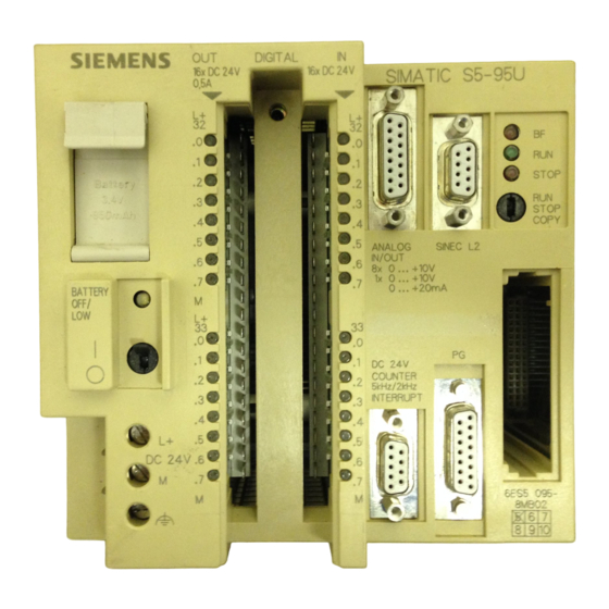
S5-95U, SINEC L2 Start-Up, Tests, and Diagnostics Start-Up, Tests, and Diagnostics This chapter describes how to start up an S5-95U programmable controller as a SINEC L2 local area network station. The first part of this chapter provides information on design and operating mode of the S5-95U with SINEC L2 interface. - Page 56 Start-Up, Tests, and Diagnostics Mode of Operation of the Programmable Controller Design and Figure 3-1 shows all the displays, operator controls and interfaces of the S5-95U (Order No. 6ES5095-8MB@ STOP O..*1W INTERRUPT Battery compartment Front panel connector for digital inputs (1 32.0 to 133.7) and for digital outputs (Q 32.0 to Q 33.7) Battery low LED ON/OFF switch...
- Page 57 S5-95U, SINEC L2 Start-Up, Tests, and Diagnostics Operating the Programmable Controller with a SINEC L2 Interface Figure 3-2 shows the operating principle of a programmable controller with the SINEC L2 interface. Programmable controller SINEC L2 interface Control Communications processor processor Operating system Handling of...
-
Page 58: Start-Up Sequence
Start-Up, Tests, and Diagnostics S5-95U, SINEC L2 START-UP Sequence In the START-UP sequence, the communications processor is activated before the START-UP OBs are processed, as illustrated in Figure 3-2. Operating mode switch set from STOP Power recovery Cold to RUN; Programmer command RUN restart routine Clear the process image I/O table, the... -
Page 59: Starting Up A System
S5-95U, SINEC L2 Start-Up, Tests, and Diagnostics Starting Up a System The following section contains suggestions for configuring and starting up a system containing programmable controllers. 3.3.1 Suggestions for Configuring and Installing the Equipment The equipment is often used as a component in a larger system. The suggestions contained in the following warning are intended to help you install your programmable controller safely. -
Page 60: Prerequisites For Starting Up The S5-95U As A Sinec L2 Station
Start-Up, Tests, and Diagnostics S5-95U, SINEC L2 3.3.2 Prerequisites for Starting Up the S5-95U as a SINEC L2 Station We assume that the S5-95U is to be connected as a station to an already existing SINEC L2 local area network. Minimum hardware requirement: •... -
Page 61: System Startup Diagnostics And Procedures
S5-95U, SINEC L2 Start-Up, Tests, and Diagnostics 3.3.3 System Startup Diagnostics and Procedures BF LED fault display The BF (Bus Fault) LED lights up when • the firmware of the S5-95U detects a fault, or • if the communications processor integrated in the S5-95U is not activated. Table 3-1. - Page 62 Start-Up, Tests, and Diagnostics S5-95U, SINEC L2 Test Possibilities during Start-Up The S5-95U provides the two following types of diagnostics functions: • Functions for the general diagnostics of the SINEC L2 bus • Functions for diagnostics of the specific data transmission types (standard connection, PLC-to- PLC, cyclic I/O, layer 2 services) The functions for diagnostics of the different data transmission types are explained in the corresponding chapters.
- Page 63 S5-95U, SINEC L2 Start-Up, Tests, and Diagnostics Power ON and mode selector at STOP Program L2 interface in LAN bus connector is not plugged into L2 interface; switch mode selector from STOP to RUN (PLC cold restart) Switch PLC to STOP and DB1 contains error(s) eliminate error in DB1 PLC enters RUN mode?
-
Page 64: Principle Of Operation
Start-Up, Tests, and Diagnostics S5-95U, SINEC L2 FMA Services This section provides you with the following information: • What is meant by FMA services • Why FMA services are used • Which FMA services are relevant for the L2 interface of the S5-95U •... - Page 65 S5-95U, SINEC L2 Start-Up, Tests, and Diagnostics An FMA request consists of an 8-byte header. The confirmation, depending on the service, consists of a maximum of 58 bytes. Bytes 0 to 7 are assigned to the confirmation header; the requested data start with byte 8. Figure 3-8 shows the structure of a service request and of a confirmation.
- Page 66 Start-Up, Tests, and Diagnostics S5-95U, SINEC L2 3.4.2 The Types of FMA Services The L2 interface of the S5-95U permits only the FMA services listed in Table 3-2. Table 3-2. FMA Services Possible with the L2 Interface of the S5-95U FMA Service Function LAS_LIST_CREATE...
- Page 67 S5-95U, SINEC L2 Start-Up, Tests, and Diagnostics 3.4.3 Assigning Parameters in DB1 for the FMA Services The default settings of DB1 do not enable the FMA services. To activate the FMA services, set the following parameters in DB1: • The job number A-NR=200 (200 is reserved for FMA services) •...
- Page 68 Start-Up, Tests, and Diagnostics S5-95U, SINEC L2 3.4.4 Managing of all FMA Services with FB222 FB222 (named AG95/FMA) allows you, with a minimum of programming, to initiate and monitor FMA jobs, and to react to them. You program FB222 once for a given S5-95U. FB222 can be used for all the FMA services.
- Page 69 S5-95U, SINEC L2 Start-Up, Tests, and Diagnostics FB222 Explanation SEGMENT 1 0000 NAME : AG95/FMA I/Q/D/B/T/C: I BI/BY/W/D: BI CODE I/Q/D/B/T/C: I BI/BY/W/D: W CONF I/Q/D/B/T/C: Q BI/BY/W/D: BI INDI I/Q/D/B/T/C: Q BI/BY/W/D: BI FEHL I/Q/D/B/T/C: Q BI/BY/W/D: BI Call up DB for received data. 0008 DB 200 000A...
- Page 70 Start-Up, Tests, and Diagnostics S5-95U, SINEC L2 FB222 (continued) Explanation Prepare indirect parameter setting. 0052 Load parameters for FB L2-SEND in DB1. 0054 A-NR 0056 KF +200 0058 QTYP 005A KS DB 005C DBNR 005E KY 0,200 0060 QANF 0062 KF +5 0064 QLAE...
-
Page 71: Reading Out A List Of All Active Stations On The Network (Las_List_Create)
S5-95U, SINEC L2 Start-Up, Tests, and Diagnostics 3.4.5 Reading Out a List of All Active Stations on the Network (LAS_LIST_CREATE) The LAS_LIST_CREATE (List of Active Stations) service delivers a list of all active stations on the network up to HSA. The creation of this list does not burden the bus (local service). - Page 72 Start-Up, Tests, and Diagnostics S5-95U, SINEC L2 The status bytes of the stations are located in the confirmation block as shown in Figure 3-10. =Station does not exist or is passive =Station active, waiting for the token =Station active (connected) Figure 3-11.
-
Page 73: Reading The Status Of Another Station (Fdl_Status)
S5-95U, SINEC L2 Start-Up, Tests, and Diagnostics 3.4.6 Reading the Status of Another Station (FDL_STATUS) The FDL_STATUS service delivers information about the status of another station on the network (remote service). Structure the FDL_STATUS request The data are stored in the FDL_STATUS block as follows: confirmation block as follows: Request Block... - Page 74 Start-Up, Tests, and Diagnostics S5-95U, SINEC L2 The status information may be contained in byte 8 of the confirmation block as shown in Figure 3-12. = remote station is passive = no acknowledgement from remote station = remote, active station ready to be connected = remote, active station is connected Figure 3-13.
-
Page 75: Reading Updated Bus Parameters (Read_Value)
S5-95U, SINEC L2 Start-Up, Tests, and Diagnostics 3.4.7 Reading Updated Bus Parameters (READ_VALUE) The READ_VALUE service allows you to read out the updated bus parameters of the local station. Structure the READ_VALUE The data are stored in the READ_VALUE request block as follows: confirmation block as follows: Request Block Confirmation Block... - Page 76 Start-Up, Tests, and Diagnostics S5-95U, SINEC L2 Table 3-8 lists the parameters, their meanings and their permissible range of values of the bus parameter block for the STB display ‘Job completed without error’ (see detailed explanation of the parameters in section 1.4). Table 3-8.
- Page 77 S5-95U, SINEC L2 Start-Up, Tests, and Diagnostics Calling Up FB222 and Storing the Data with FMA Service READ_VALUE Explanation Load service_code in ACCUM and transfer to flag word 0008 KH 000B 0009 FW 2 (see section 3.4.4) 000A FB 222 000B NAME: AG95/FMA...
-
Page 78: Reading Out Available Token Hold Time When Receiving The Token
Start-Up, Tests, and Diagnostics S5-95U, SINEC L2 3.4.8 Reading Out Available Token Hold Time When Receiving the Token (TIME_TTH_READ) The TIME_TTH_READ service gives you the available token hold time when receiving the token. It is very useful in the start-up phase for setting the target rotation time. If the available token hold time moves towards zero, you must assign a higher value to the target rotation time. - Page 79 S5-95U, SINEC L2 Start-Up, Tests, and Diagnostics Calling Up FB222 and Storing the Data with FMA Service TIME_TTH_READ Explanation Load service_code in ACCUM and transfer to flag word 0008 KH 0023 0009 FW 2 (see section 3.4.4) 000A FB 222 000B NAME: AG95/FMA...
-
Page 80: Reading Out The Event Message (Mac_Event)
Start-Up, Tests, and Diagnostics S5-95U, SINEC L2 3.4.9 Reading Out the Event Message (MAC_EVENT) This FMA service is for reading out fault events. It is useful for testing during start-up. Principle of Operation (represented in Figure 3-16) • Errors recognized by the communications processor (e.g., double token, frame errors) are indicated automatically. - Page 81 ... B1 , C0 ... FF your nearest Siemens representative If temporary errors occur often in your network, check the network configuration. The errors could be caused by hardware problems on the network, such as faulty cables, bus connectors, etc.
- Page 82 Start-Up, Tests, and Diagnostics S5-95U, SINEC L2 Calling Up FB222 and Storing the Data with FMA Service MAC_EVENT Explanation ( section 3.4.4) 000A FB 222 000B NAME: AG95/FMA irrelevant 000C REQ: irrelevant 000D CODE: FW 2 irrelevant 000E CONF: FB222 message: indication was received 0010 INDI: FB222 message: error occurred in PAFE or STB...
- Page 83 Data Transmission Using a Standard Connection Features of a Standard Connection ..... . . 4 - 1 Assigning Parameters in DB1 of the S5-95U for Data Exchange with Standard Connections .
- Page 84 Figures 4-1. Example of a Hardware Configuration for a Standard Connection ..4 - 1 4-2. Functional Diagram of a Standard Connection ..... 4 - 2 4-3.
-
Page 85: Data Transmission Using A Standard Connection
S5-95U, SINEC L2 Data Transmission Using a Standard Connection Data Transmission Using a Standard Connection This chapter provides you with the following information: • How this type of data transmission functions in principle • How to set parameters for the programmable controllers •... - Page 86 Data Transmission Using a Standard Connection S5-95U, SINEC L2 Principle of Operation For this type of communication you need to define the following once: • The send mailbox (SF) that contains the transmit data (maximum 242 bytes). • The send coordination byte (CBS) that coordinates between user program and SINEC L2. •...
-
Page 87: Assigning Parameters In Db1 Of The S5-95U For Data Exchange With
S5-95U, SINEC L2 Data Transmission Using a Standard Connection Assigning Parameters in DB1 of the S5-95U for Data Exchange with Standard Connections You assign the following parameters in DB1: • The location of the send mailbox (SM). • The location of the receive mailbox (RM). •... - Page 88 Data Transmission Using a Standard Connection S5-95U, SINEC L2 Example: Two S5-95U programmable controllers are to communicate using a standard connection. Table 4-2. Setting Parameters for Standard Connections DB1 PLC 1 Explanation L2 basic parameter (see section 1.4) 156: SL2: TLN 1 STA AKT';...
-
Page 89: Transmitting Data
S5-95U, SINEC L2 Data Transmission Using a Standard Connection Transmitting Data There are two prerequisites for transmitting data: • The parameters for the locations of SF and CBS are set in data block DB1 (see section 4.2). • The transmit data, additional information (length of the transmit data (“net data”), and the station address of the receiver) have been transferred to the send mailbox. - Page 90 Data Transmission Using a Standard Connection S5-95U, SINEC L2 Structure of the Send Coordination Byte (CBS) Figure 4-5 shows the structure of the send coordination byte (CBS). No error during the last data transmission Error during the last data transmission (Bits 1 to 5 describe the cause for an error in more detail.) The destination programmable controller...
-
Page 91: Receiving Data
S5-95U, SINEC L2 Data Transmission Using a Standard Connection Receiving Data Prerequisites for receiving data: You have set the parameters for the location of the receive mailbox (RM) and receive coordination byte (CBR) in data block DB1 (see section 4.2). Figure 4-6 shows where information is stored when it is received. - Page 92 Data Transmission Using a Standard Connection S5-95U, SINEC L2 Structure of the Receive Coordination Byte (CBR) Figure 4-7 shows the structure of the receive coordination byte (CBR). No error Error during the last data transmission (Bits 2 and 5 describe the error cause in more detail.) No error Receive mailbox error (The DB is not...
-
Page 93: Programming Example For Data Transmission Via A Standard Connection
S5-95U, SINEC L2 Data Transmission Using a Standard Connection Programming Example for Data Transmission via a Standard Connection This section explains the structure of the control program in the following example: Programmable controller 1 is to receive data from programmable controller 2 and to transmit data to programmable controller 2. - Page 94 Data Transmission Using a Standard Connection S5-95U, SINEC L2 Programmable Controller 1 Proceed as follows: Assign parameters in DB1 of programmable controller 1 as described in section 4.2. Program the individual blocks as described in the following section. Transfer blocks DB1, OB1, DB6, and DB7 to programmable controller 1. Cyclical Program for Station 1 (Programmable Controller 1) The following was set in DB1: •...
- Page 95 S5-95U, SINEC L2 Data Transmission Using a Standard Connection FB1 for PLC 1 (continued) Explanation 0014 M001: If transmit trigger bit is 0 or 0015 : ON = ANST send mailbox is enabled to transmit, or 0016 F 62.7 transmit disabling bit is set, 0017 F 71.2 jump to edge evaluation ‘Job completed’.
- Page 96 Data Transmission Using a Standard Connection S5-95U, SINEC L2 Programmable Controller 2 Proceed as follows: Assign parameters in the DB1 of programmable controller 2 as described in section 4.2. Program the individual blocks as described in the following section. Transfer blocks DB1, OB1, DB8, and DB9 to programmable controller 2. Cyclical Program for Station 2 (Programmable Controller 2) The following was set in DB1: •...
- Page 97 S5-95U, SINEC L2 Data Transmission Using a Standard Connection FB1 for PLC 2 (continued) Explanation 0014 M001: If transmit trigger bit is 0, or 0015 : ON = ANST send mailbox is enabled to transmit, or 0016 F 60.7 transmit disabling bit is set, 0017 F 71.2 jump to edge evaluation ‘Job completed’.
-
Page 98: Broadcast Request ("Transmit To All")
Data Transmission Using a Standard Connection S5-95U, SINEC L2 Broadcast Request (“Transmit to All”) “Broadcasting” means that one active station transmits a message to all active and all passive stations. Active S5-95U S5-95U . . . stations (Sender) (receiver) Passive S5-95U . - Page 99 Integral Standard Function Blocks L2-SEND and L2-RECEIVE Parameters for L2-SEND and L2-RECEIVE ....5 - 2 Direct and Indirect Parameter Settings for the L2 Function Blocks 5 - 4 Parameter Assignment Error Byte (PAFE) .
- Page 100 Figures 5-1. Information Transport with the FB L2-SEND and FB L2-RECEIVE Function Blocks ......... . 5 - 1 5-2.
-
Page 101: Integral Standard Function Blocks L2-Send And L2-Receive
S5-95U, SINEC L2 Integral Standard Function Blocks L2-SEND and L2-RECEIVE Integral Standard Function Blocks L2-SEND and L2-RECEIVE The L2-SEND (FB252) and L2-RECEIVE (FB253) standard function blocks are already integrated in the S5-95U operating system. FB L2-SEND transports information from the control processor of the S5-95U to the communications processor of the S5-95U. -
Page 102: Parameters For L2-Send And L2-Receive
Integral Standard Function Blocks L2-SEND and L2-RECEIVE S5-95U, SINEC L2 Parameters for L2-SEND and L2-RECEIVE Function blocks L2-SEND and L2-RECEIVE use the parameters listed in Tables 5-1 and 5-2. Table 5-1. A List of Parameters Used by L2-SEND (FB252) Designation Significance Job number A-NR... - Page 103 S5-95U, SINEC L2 Integral Standard Function Blocks L2-SEND and L2-RECEIVE The formal operands that have to be specified when the standard function blocks are used are explained in Tables 5-4 and 5-5. Table 5-4. Formal Operands: Significance of the Parameters Used with L2-SEND (FB 252) Parameter Significance Parameter x is irrelevant.
-
Page 104: Direct And Indirect Parameter Settings For The L2 Function Blocks
Integral Standard Function Blocks L2-SEND and L2-RECEIVE S5-95U, SINEC L2 Direct and Indirect Parameter Settings for the L2 Function Blocks You can set parameters either directly or indirectly for the L2-SEND and L2-RECEIVE function blocks. The advantage of indirect parameter settings: you can assign new parameters to the standard function blocks from the STEP 5 program. -
Page 105: Parameter Assignment Error Byte (Pafe)
S5-95U, SINEC L2 Integral Standard Function Blocks L2-SEND and L2-RECEIVE Parameter Assignment Error Byte (PAFE) The parameter assignment error byte (PAFE) indicates errors made when assigning parameters for L2-SEND and L2-RECEIVE. Flag byte 255 is reserved as the parameter assignment error byte. You can scan the PAFE in the control program and program the reactions to errors that occur. -
Page 106: Status Byte
Integral Standard Function Blocks L2-SEND and L2-RECEIVE S5-95U, SINEC L2 Status Byte The status byte (STB) is used to control the data transmission using L2-SEND and L2-RECEIVE. You need to evaluate the status byte in order to monitor the data exchange between the control processor of the S5-95U and the communications processor of the S5-95U. - Page 107 S5-95U, SINEC L2 Integral Standard Function Blocks L2-SEND and L2-RECEIVE Note In the case of the FMA services ( section 3.4), the error codes 7 to C in bits 4 to 7 of the status byte do not exist for L2-RECEIVE. Table 5-8.
-
Page 108: Data Transmission Using Plc-To-Plc Connections
Data Transmission Using PLC-to-PLC Connections Features of the PLC-to-PLC Connections ....6 - 1 Assigning Parameters in DB1 of the S5-95U for Data Exchange with PLC-to-PLC Connections . - Page 109 Figures 6-1. Example: Hardware Configuration for PLC-to-PLC Connection ..6 - 1 6-2. Functional Diagram of a PLC-to-PLC Connection ....6 - 2 6-3.
- Page 110 S5-95U, SINEC L2 Data Transfer with PLC-to-PLC Connections Data Transmission Using PLC-to-PLC Connections This chapter provides you with the following information: • How this type of data transmission functions in principle • How to communicate with the CP 5430 communications processor •...
- Page 111 Data Transfer with PLC-to-PLC Connections S5-95U, SINEC L2 Principle of Operation Source PLC e.g., S5-95U Destination PLC e.g., S5-95U Active network station Active network station Status byte/SEND Status byte/RECEIVE to destination (A-NR) to source (A-NR) (in the flag area) (in the flag area) o.k.
- Page 112 Data Transfer with PLC-to-PLC Connections Communicating with the CP 5430 Communications Processor If you want to connect other SIMATIC S5 controllers (S5-115U, S5-135U, S5-155U) to the network, you can use the CP 5430 communications processor (see Figure 6-1). You configure the desired PLC-to-PLC connection in DB1 of the S5-95U, and program function blocks L2-SEND and L2-RECEIVE.
-
Page 113: Assigning Parameters In Db1 Of The S5-95U For Data Exchange With Plc-To-Plc Connections
Data Transfer with PLC-to-PLC Connections S5-95U, SINEC L2 Assigning Parameters in DB1 of the S5-95U for Data Exchange with PLC-to-PLC Connections There are no default settings in DB1 for the PLC-to-PLC connections. You assign the parameters in data block DB1 for the following items: •... - Page 114 S5-95U, SINEC L2 Data Transfer with PLC-to-PLC Connections The procedures to set and modify parameters in DB1 and to transfer DB1 are described in detail in section 1.4. DB1 Parameters for PLC-to-PLC Connections Table 6-2. DB1 Parameters for PLC-to-PLC Connections Parameter Argument Significance...
- Page 115 Data Transfer with PLC-to-PLC Connections S5-95U, SINEC L2 Programming Example Data Transmission PLC-to-PLC Connections Using Standard Function Blocks This section explains the structure of the control programs for two programmable controllers. Example: PLC 1 and PLC 2 are to exchange data with one another, i.e., they will transmit and receive. Refer to section 6.1 for the description of the hardware configuration.
- Page 116 S5-95U, SINEC L2 Data Transfer with PLC-to-PLC Connections Programmable Controller 1 Proceed as follows: Assign parameters in DB1 of programmable controller 1 as described in section 6.2. Program the individual blocks as described in the following section. Transfer blocks DB1, OB1, FB5, FB105, DB21 and DB22 to programmable controller 1. Cyclical Program for Station 1 (Programmable Controller 1) Programmable controller 1 is to transmit data to programmable controller 2 and to receive data from programmable controller 2.
- Page 117 Data Transfer with PLC-to-PLC Connections S5-95U, SINEC L2 FB5 for PLC 1 Explanation Segment 1 0000 Transmitting from station 1 to station 2 NAME S 1=>2 ANST I/B/D/B/T/Z: I BI/BY/W/D: BI Edge evaluation 0009 “Job completed without error” via 000A STBS = flag byte FY10 000B STBS bit “Job completed without error”...
- Page 118 S5-95U, SINEC L2 Data Transfer with PLC-to-PLC Connections FB105 for PLC 1 Explanation Netzwerk 1 Station 1 receives from station 2 NAME R 1<=2 EMPF I/Q/D/B/T/Z: I BI/BY/W/D: BI If receiving is not enabled or 000A : ON =EMPF if STBR bit “Receive viable” is not set, 000B : ON F 11.0...
- Page 119 Data Transfer with PLC-to-PLC Connections S5-95U, SINEC L2 Programmable Controller 2 Proceed as follows: Assign parameters in the DB1 of programmable controllers 2 as described in section 6.2. Program the individual blocks as described in the following section. Transfer blocks DB1, OB1, FB1, DB21 and DB22 to programmable controller 2. Cyclical Program for Station 2 (Programmable Controller 2) Programmable controller 2 is to transmit data to programmable controller 1 and to receive data from programmable controller 1.
- Page 120 S5-95U, SINEC L2 Data Transfer with PLC-to-PLC Connections FB5 for PLC 2 Explanation SEGMENT 1 0000 Transmitting from station 2 to station 1 NAME S 2=>1 ANST I/Q/D/B/T/Z: I BI/BY/W/D: BI Edge evaluation 0009 “Job completed without error” via 000A STBS = flag byte FY21 000B STBS bit “Job completed without error”...
- Page 121 Data Transfer with PLC-to-PLC Connections S5-95U, SINEC L2 FB105 for PLC 2 Explanation SEGMENT 1 Station 2 receives from station 1 NAME S 2<=1 EMPF I/Q/D/B/T/Z: I BI/BY/W/D: BI If receiving is not enabled or 000A : ON =EMPF if STBR bit “Receive viable” is not set, 000B : ON F 22.0...
-
Page 122: Data Transmission Using Cyclic I/O
Data Transmission Using Cyclic I/O Features of Cyclic I/O ....... . 7 - 1 Assigning Parameters in DB1 of the S5-95U for Data Exchange with Cyclic I/O . - Page 123 Figures 7-1. Functional Diagram of Cyclic I/O ....... 7 - 2 7-2.
-
Page 124: Data Transmission Using Cyclic I/O
S5-95U, SINEC L2 Data Transmission Using Cyclic I/O Data Transmission Using Cyclic I/O This chapter provides you with the following information: • How this type of data transmission functions in principle • How to set parameters for the programmable controllers •... - Page 125 Data Transmission Using Cyclic I/O S5-95U, SINEC L2 Principle of Operation A reserved data block (ZP DB) is responsible in the S5-95U for the word-by-word data exchange. The cyclic I/O input area (ZPE) and cyclic I/O output area (ZPA) for the respective stations are defined in data block ZP DB.
- Page 126 S5-95U, SINEC L2 Data Transmission Using Cyclic I/O Updating the Cyclic I/O Input Area and Output Area There is an exchange of ZP data (ZPA, ZPE, and ZP status bytes) between the control processor and the communications processor at every cycle control point in the programmable controller's CPU program cycle.
-
Page 127: Assigning Parameters In Db1 Of The S5-95U For Data Exchange With Cyclic I/O
The CP 5430 communications processor is required when S5-95U programmable controllers communicate via cyclic I/O (ZP) with the SIMATIC S5-115U to S5-155U controllers. The CP 5430 functions as the ZP master. The S5-95U functions as the ZP slave. Section 7.2 describes how to set the parameters for the S5-95U. - Page 128 S5-95U, SINEC L2 Data Transmission Using Cyclic I/O Examples: ZP DBx for ZP Master ZPE of ZP slave 1 DW 1 ... ZPE of ZP slave 2 ZPE of ZP slave 23 Complete ZP input ZPE of ZP slave 31 area (max.
- Page 129 Data Transmission Using Cyclic I/O S5-95U, SINEC L2 The procedures to set and modify parameters in DB1 and to transfer DB1 are described in detail in section 1.4. DB1 Parameters for Cyclic I/O Table 7-1. DB1 Parameters for Cyclic I/O Parameter Argument Significance...
-
Page 130: Controlling Data Transmission In The Control Program
S5-95U, SINEC L2 Data Transmission Using Cyclic I/O Example: Four S5-95Us are to communicate using cyclic I/O. Programmable controller 1 is the ZP master, programmable controllers 40, 41 and 42 (all of them passive) are the ZP slaves. Some of the default parameters (represented shaded in Table 7-2) in DB1 need to be modified. - Page 131 Data Transmission Using Cyclic I/O S5-95U, SINEC L2 Status Byte for the ZP Master Error codes Status codes No ZPE cycle overflow ZPE cycle overflow: new ZP input data are available in DB ZP from all ZP slaves although the CPU could not yet take over the previous ZP input data .
- Page 132 S5-95U, SINEC L2 Data Transmission Using Cyclic I/O ZP Slave Life List The ZP master (S5-95U) creates a ZP slave life list that contains the status of of every ZP slave scanned by the ZP master. The remaining entries in the list are zeros. There is an entry in the ZP slave life list when the ZP master scans the ZP slave and either a ZP configuration error (STB bit 6) or a ZP slave failure (STB bit 7) occurs.
- Page 133 Data Transmission Using Cyclic I/O S5-95U, SINEC L2 Status Byte for the ZP Slave: Error codes Status codes 0: No ZPE cycle overflow 1: ZPE cycle overflow: New ZP input data are available in ZP DB from ZP master although the CPU could not yet take over previous ZP input data. 0: No ZPA cycle overflow 1: ZPA cycle overflow: The CPU has provided new ZP output data from the ZP DB to...
- Page 134 S5-95U, SINEC L2 Data Transmission Using Cyclic I/O ZP Slave Watchdog The S5-95U as a ZP slave has a watchdog. If the ZP slave is not scanned cyclically within the “response time” by a ZP master, bit 7 “ZP master failure” is set in the ZP slave status byte and the entire ZPE in ZP DB is set to zero.
-
Page 135: Programming Example For Data Transmission Via Cyclic I/O
Data Transmission Using Cyclic I/O S5-95U, SINEC L2 Programming Example for Data Transmission via Cyclic I/O This section explains the structure of the control programs for cyclic I/O. The data are exchanged cyclically without request to transmit or request to receive: The data exchange is controlled within the control program only by the status byte. - Page 136 S5-95U, SINEC L2 Data Transmission Using Cyclic I/O FB202 for PLC 1 (ZP Master) Explanation SEGMENT 1 0000 NAME ZP-ST-LI SL40 I/Q/D/B/T/Z: Q BI/BY/W/D: BI SL41 I/Q/D/B/T/Z: Q BI/BY/W/D: BI SL42 I/Q/D/B/T/Z: Q BI/BY/W/D: BI FEHL I/Q/D/B/T/Z: Q BI/BY/W/D: BI If ZP data in ZP DB and ZP slave life list are 0008 F 100.4...
- Page 137 Data Transmission Using Cyclic I/O S5-95U, SINEC L2 DB202 for PLC 1 (ZP Master) Explanation ZP slave life list = 00000000 00000000; = 00000000 00000000; Status of : Station 40= D 2.7; = 00000000 00000000; Station 41= D 2.6; = 00000000 00000000; Station 42= D 2.5 = 00000000 00000000;...
- Page 138 S5-95U, SINEC L2 Data Transmission Using Cyclic I/O Cyclical Program for Stations 40, 41, and 42 (ZP Slaves) The structure of the programs is identical for the three ZP slaves. It is represented only once in the following section. The status byte for the ZP slave is flag byte FY100. ZP DB for the ZP slave is DB100. Proceed as follows: Assign parameters for programmable controller 2 (station 40), programmable controller 3...
-
Page 139: Data Transmission By Accessing Layer 2 Services
Data Transmission by Accessing Layer 2 Services Characteristic Features of Layer 2 Access Data Transmission ..8 - 2 Types and Characteristic Features of the Layer 2 Services ..8 - 5 Assigning the S5-95U Parameters for Data Communications . - Page 140 Figures 8-1. Example: Hardware Configuration Using Layer 2 Services ... . . 8 - 2 8-2. Function Model Using Layer 2 Services ......8 - 3 8-3.
-
Page 141: Data Transmission By Accessing Layer 2 Services
S5-95U, SINEC L2 Data Transmission by Accessing Layer 2 Services Data Transmission by Accessing Layer 2 Services In this chapter, you will learn • the basic principles underlying this type of transmission, • how to assign the PLC's parameters, and •... - Page 142 Data Transmission by Accessing Layer 2 Services S5-95U, SINEC L2 Characteristic Features of Layer 2 Access Data Transmission • Layer 2 accesses are used for communications between active stations or between active and passive stations. • In DB1, you can program up to 23 layer 2 accesses for sending data and up to 23 layer 2 accesses for receiving data.
- Page 143 S5-95U, SINEC L2 Data Transmission by Accessing Layer 2 Services Sending PLC e.g. S5-95U Receiving PLC e.g. S5-95U Active station on the LAN bus Active or passive station on the LAN bus 'Send' status byte for job 'Send' status byte for job 'Receive' status byte for number number...
- Page 144 Data Transmission by Accessing Layer 2 Services S5-95U, SINEC L2 Request, Indication and Confirmation Request: A layer 2 service is invoked from the STEP 5 program with a request. The request consists of the request header and the net data to be sent. The request header is interpreted by the communications processor of the sending PLC.
- Page 145 S5-95U, SINEC L2 Data Transmission by Accessing Layer 2 Services Types and Characteristic Features of the Layer 2 Services You have the following layer 2 services at your disposal: Table 8-1. Layer 2 Services of the L2 Interface of the S5-95U Layer 2 Service When Do You Use this Service can be Used if...
- Page 146 Data Transmission by Accessing Layer 2 Services S5-95U, SINEC L2 SAPs and Job Numbers The communications processor has buffers for the data to be sent and the data received. These buffers are referred to as SAPs (Service Access Points to layer 2) An SAP is addressed by assigning it a number.
- Page 147 S5-95U, SINEC L2 Data Transmission by Accessing Layer 2 Services Explanation of Figure 8-3: A request is passed to SAP 33 from the STEP 5 program by L2-SEND. Job number (A-NR) 33 indicates that L2-SEND accesses SAP 33. In the case of a request, the following always applies: Job number = SAP number The communications processor sends the net data of the request to the receiver and deposits them in the SAP.
- Page 148 Data Transmission by Accessing Layer 2 Services S5-95U, SINEC L2 Request Confirmation Indication Byte Byte Byte com_class com_class com_class FDL_Request=00 FDL_Confirmation=01 Indication=02 (request for layer 2 service) (Confirmation from layer 2 (indication that data have been firmware following request) received) user_id user_id User-definable ID...
- Page 149 S5-95U, SINEC L2 Data Transmission by Accessing Layer 2 Services Assigning the S5-95U Parameters for Data Communications There is no default setting in DB1 for layer 2 accesses. You assign the following parameters in DB1: • The location of a 'Send' status byte for L2-SEND and L2-RECEIVE with the corresponding SAP number.
- Page 150 Data Transmission by Accessing Layer 2 Services S5-95U, SINEC L2 The procedures to follow for entering, modifying and transferring DB1 are described in detail in section 1.4. DB1 Parameters for Layer 2 Services Table 8-3. Layer 2 Services, DB1 Parameters Parameter Argument Meaning...
- Page 151 S5-95U, SINEC L2 Data Transmission by Accessing Layer 2 Services FBs for Managing All Layer 2 Services FB223 and FB224 enable you to transmit data using layer 2 services with minimal programming overhead. You only need to program these FBs once for an S5-95U. The FBs can be used for all layer 2 services.
- Page 152 Data Transmission by Accessing Layer 2 Services S5-95U, SINEC L2 Meaning of the Parameters of FB223 and FB224: ”ANST”: Input parameter bit The request job is initiated when this bit is set. Set the bit before invoking FB223. FB223 resets the bit once L2-SEND and L2- RECEIVE have executed without error. ”LSTA”: Output parameter byte FB223 tells you the link_status of the confirmation.
- Page 153 S5-95U, SINEC L2 Data Transmission by Accessing Layer 2 Services FB223 (Cont.) Explanation ***** Save parameter assignment error 255.0 byte for subsequent evaluation 20.6 ***** If STBS "Receive viable" set 77.0 Invoke L2-RECEIVE :JC FB 253 Name :L2-REC Job number for confirmation = 48 A-NR : KY 0,48 Data are in...
- Page 154 Data Transmission by Accessing Layer 2 Services S5-95U, SINEC L2 FB224 Explanation Segment 1 0000 Fetch indication Name :EMPFANG :EMPF I/Q/D/B/T/Z: I BI/BY/W/D: BI Only the indications of layer 2 services are fetched in this FB If receive is not enabled or the =EMPF STBR bit "Receive viable"...
- Page 155 S5-95U, SINEC L2 Data Transmission by Accessing Layer 2 Services Sending Data to a Station (SDA Service) The SDA (Send Data with Acknowledge) layer 2 service is used if an active station is to send data to an active or passive station. Data transmission schematic ( Figure 8-6): The request (header + net data to be transmitted) in the flag or data area is sent with L2-SEND (= request an layer 2).
- Page 156 Data Transmission by Accessing Layer 2 Services S5-95U, SINEC L2 Request Confirmation Indication Byte Byte Byte com_class com_class com_class FDL_Request=00 Confirmation=01 Indication=02 user_id user_id User-definable ID ID assigned in connection with irrelevant a request service_code service_code service_code Type of service requested Type of service: Type of service: SDA=00...
- Page 157 S5-95U, SINEC L2 Data Transmission by Accessing Layer 2 Services link_status Message in the Confirmation Header Table 8-5. link_status Message for SDA Value of Abbreviation Meaning link_status (PROFIBUS) Positive acknowledgement, service executed Negative acknowledgement; remote PLC is in STOP mode Prerequisite: Destination station is an S5-95U and the connection has been properly configured at the destination station Negative acknowledgement;...
- Page 158 Data Transmission by Accessing Layer 2 Services S5-95U, SINEC L2 Invoking FB224 for SDA OB1 (Receiving PLC) Explanation Fetch indication ( section 8.4) :JU FB 224 Name :EMPFANG Enable receive EMPF : Storing Request and Confirmation at the Sender DB33 Explanation ****Request frame**** KH = 0000;...
- Page 159 S5-95U, SINEC L2 Data Transmission by Accessing Layer 2 Services Sending Data to Several Stations (SDN) The SDA (Send Data with No Acknowledge) layer 2 service is used if an active station is to send data to several active or passive stations (multicasting). Data can also be sent to one active or passive station with the SDN service.
- Page 160 Data Transmission by Accessing Layer 2 Services S5-95U, SINEC L2 Figure 8-9 shows the request, confirmation and indication structures for the SDN service Request Confirmation Indication Byte Byte Byte com_class com_class com_class FDL_Request=00 Confirmation=01 Indication=02 user_id user_id User-definable ID ID assigned in connection with irrelevant a request service_code...
- Page 161 S5-95U, SINEC L2 Data Transmission by Accessing Layer 2 Services link_status Message in the Confirmation Header Table 8-6. link_status Messages for SDN Value of Abbreviation Meaning link_status (PROFIBUS) Positive acknowledgement; transmission of data from the sending (local) station completed - Illegal parameters in the request header or - Local station is passive or - Destination station is own station address or - If own SAP = default SAP...
- Page 162 Data Transmission by Accessing Layer 2 Services S5-95U, SINEC L2 Storing Request and Confirmation at the Sender DB33 Explanation ****Request frame**** KH = 0000; com_class / user_id KY = 000,000; service_code / irrelevant KY = 001,000; service_class/destination SAP KY = 000,048; rem_add_station / rem_add_segm KY = 002,255;...
- Page 163 S5-95U, SINEC L2 Data Transmission by Accessing Layer 2 Services Holding Data for Fetching Once Only by a Station (RUP_SINGLE Service) The RUP_SINGLE (Reply UPdate SINGLE) service is used for holding data for fetching in an active or passive station. The data held can be fetched by an active station once only, using the SRD service ( section 8.9).
- Page 164 Data Transmission by Accessing Layer 2 Services S5-95U, SINEC L2 Request Confirmation Byte Byte com_class com_class FDL_Request=00 Confirmation=01 user_id user_id User-definable ID ID assigned in connection with a request service_code service_code Type of service requested: Type of service: RUP_SINGLE=06 RUP_SINGLE=06 link_status irrelevant ( Table 8-7 )
- Page 165 S5-95U, SINEC L2 Data Transmission by Accessing Layer 2 Services Invoking FB223 and FB224 with the RUP_SINGLE Service in the Receiving PLC (holds data ready for fetching) OB1 (Receiving PLC) Explanation Send request and fetch confirmation ( section 8.4) :JU FB 223 Name :SENDER Send initiation bit for the RUP_SINGLE service ANST :...
- Page 166 Data Transmission by Accessing Layer 2 Services S5-95U, SINEC L2 Holding Data Ready for Fetching Several Times Over by One or More Stations (RUP_MULTIPLE Service) The RUP_MULTIPLE (Reply UPdate MULTIPLE) service is used for holding data for fetching in an active or passive station.
- Page 167 S5-95U, SINEC L2 Data Transmission by Accessing Layer 2 Services Figure 8-13 shows the request and confirmation structures for the RUP_MULTIPLE service. Request Confirmation Byte Byte com_class com_class FDL_Request=00 Confirmation=01 user_id user_id User-definable ID ID assigned in connection with a request service_code service_code Type of service requested:...
- Page 168 Data Transmission by Accessing Layer 2 Services S5-95U, SINEC L2 Invoking FB223 and FB224 with the RUP_MULTIPLE Service in the Receiving PLC (holds data ready for fetching) OB1 (Receiving PLC) Explanation Send request and fetch confirmation ( section 8.4) :JU FB 223 Name :SENDER Send initiation bit for the RUP_MULTIPLE service ANST :...
-
Page 169: Sending Data And Fetching Data From A Station (Srd Service)
S5-95U, SINEC L2 Data Transmission by Accessing Layer 2 Services Sending Data and Fetching Data from a Station (SRD Service) The SRD (Send and Request Data with Reply) layer 2 service is used by an active station to send data to an active or passive station and/or fetch data from an active or passive station. Prerequisite for data transmission: You must hold data requested by the sender ready for fetching with the RUP_SINGLE ( section 8.7) or RUP_MULTIPLE layer 2 service ( section 8.8) - Page 170 Data Transmission by Accessing Layer 2 Services S5-95U, SINEC L2 Requesting Data (SRD Layer 2 Service without Send Data) If you do not want your sender to send any data to the receiver, but only request data from the receiver, use the special case of the "SRD without send data" layer 2 service. Prerequisite for data transmission: You must hold data requested by the sender ready for fetching with the RUP_SINGLE ( section 8.7) or RUP_MULTIPLE layer 2 service ( section 8.8).
- Page 171 S5-95U, SINEC L2 Data Transmission by Accessing Layer 2 Services link_status Message in the Confirmation Header Table 8-9. link_status Messages for the SRD Service Value of Abbreviation Meaning link_status (PROFIBUS) Positive acknowledgement for data sent; reply data with low priority available Positive acknowledgement for data sent;...
- Page 172 Data Transmission by Accessing Layer 2 Services S5-95U, SINEC L2 Invoking FB223 for SRD OB1 (Sending PLC) Explanation Send request and fetch confirmation ( section 8.4) :JU FB 223 Name :SENDER Send initiation bit for the SRD service ANST : Flag byte contains the link_status of the confirmation LSTA : Invoking FB223 and FB224 for the RUP_SINGLE and/or RUP_MULTIPLE Service in the...
- Page 173 S5-95U, SINEC L2 Data Transmission by Accessing Layer 2 Services Storing Request and Confirmation at the Sender DB33 Explanation ****Request frame**** KH = 0000; com_class / user_id KY = 000,000; service_code / irrelevant KY = 003,000; service_class / destination SAP KY = 000,048;...
-
Page 174: Programmer Functions Over The Sinec L2 Network
Programmer Functions Over the SINEC L2 Network Programmer Functions ....... . 9 - 2 Selecting the L2 Interface . - Page 175 Figures 9-1. ”INTERFACE SELECTION” Screen ......9 - 3 9-2. The ”FUNCTION SELECTION/DEFAULTS” Screen of the ”BUS DIALLING”...
-
Page 176: Programmer Functions Over The Sinec L2 Network
S5-95U, SINEC L2 Programmer Functions Over the SINEC L2 Network Programmer Functions Over the SINEC L2 Network This chapter will show you • which programmer functions can be implemented over the SINEC L2 LAN for the S5-95U, • how to establish the connection to a remote station from the programmer, and •... -
Page 177: Programmer Functions Over The Sinec L2 Network
Programmer Functions Over the SINEC L2 Network S5-95U, SINEC L2 Programmer Functions The S5-95U can only be operated as a programmer slave on the SINEC L2 LAN, i.e. you cannot • implement programmer functions over the LAN at another station from the control program of an S5-95U, •... -
Page 178: Selecting The L2 Interface
( Figure 9-1), and confirm with <F6> (SAVE): I N T E R F A C E S E L E C T I O N SIMATIC S5 / KOMI > Select interface using cursor keys > Select special IM511 protocol with F3... -
Page 179: Entering Defaults
Choose names for the pathfile (e.g. C:TEST@@AP.INI), the footer file (if you want a footer) and the printer file (if you have defined printer parameters for the printer with the "PRINTER" utility). SIMATIC S5 / ODS01 F U N C T I O N... -
Page 180: Editing A Path
S5-95U, SINEC L2 Programmer Functions Over the SINEC L2 Network Editing a Path Supposing you want to use a programmer connected direct to the SINEC L2 LAN to reach the station with LAN address 2. The endpoint of the path is to be the S5-95U with the station address 2. Figure 9-3 shows an example of how to edit the path ( Figure 9-3) with the "LAN SELECT"... - Page 181 Programmer Functions Over the SINEC L2 Network S5-95U, SINEC L2 Press key <F1> in the "FUNCTION SELECTION/DEFAULTS" screen. The following screen appears: PG/CP-L2 PATH NAME : ST2/95U SINEC L2 DELETE AUX. CP PG-L2 CP-L2 SAVE ELEMENT FUNCTION Figure 9-4. Screen for Editing a Path (1) Press <F8>...
- Page 182 S5-95U, SINEC L2 Programmer Functions Over the SINEC L2 Network The screen changes to the following: PG/CP-L2 PATH NAME :ST 2/95U SINEC L2 CP-L2 ADDRESS : AUX. COOR/ DELETE FUNCTION ENDP CP-L2 CP-L1 SAVE ELEMENT Figure 9-5. Screen for Editing a Path (2) Change the default address "0"...
- Page 183 Programmer Functions Over the SINEC L2 Network S5-95U, SINEC L2 Press <F4> (ACTIVATE) in the "FUNCTION SELECTION/DEFAULTS" screen. The edited path appears on the monitor. PG/CP-L2 PATH NAME : ST2/95U SINEC L2 CP-L2 ADDRESS : ENDP SYSID SUBPATH TOTAL EXIT Figure 9-6.
- Page 184 S5-95U, SINEC L2 Programmer Functions Over the SINEC L2 Network You can also edit more complex paths. For example, you can edit a path from a programmer on the SINEC H1 LAN to an S5-95U on the SINEC L2 LAN. Proceed exactly as described on the previous pages. The edited path will then appear as follows on your monitor: PATHNAME : ST 2/95U CP-H1...
-
Page 185: Setting The L2 Basic Parameters On The Programmer
Programmer Functions Over the SINEC L2 Network S5-95U, SINEC L2 Setting the L2 Basic Parameters on the Programmer The following display appears when you press <F1> (SET SYSID) in the "FUNCTION SELECTION/DEFAULTS" screen: S Y S I D (L O C A L) LAN PARAMETERS : (PLEASE REMEMBER THAT EACH INCORRECT MODIFICATION OF THE DEFAULT VALUES CAN IMPAIR THE OPERABILITY OF THE... -
Page 186: Appendices
Appendices Appendix A DB1 Parameters, DB1 Parameter Assignment Errors, Calculation of Target Rotation Time Appendix B SAP Numbers / Job Numbers Appendix C List of Abbreviations/ Glossary Appendix D List of Accessories and Order Numbers Appendix E Technical Specifications; PLC Cycle Delay Times Caused by SINEC L2 Operations Appendix F S5-95U Communications Matrix and Emulation of Types of Data Transmission in... - Page 187 DB1 Parameters, DB1 Parameter Assignment Errors, Calculation of Target Rotation Time EWA 4NEB 812 6112-02...
-
Page 188: Adb1 Parameters, Db1 Parameter Assignment Errors
S5-95U, SINEC L2 DB1 Parameters, DB1 PAFE, TRT DB1 Parameters, DB1 Parameter Assignment Errors, Calculation of Target Rotation Time Parameter Argument Significance Block ID: SL2: SINEC L2 Basic Parameters for all Functions Own station address AKT/PAS Own station status Baud rate Highest L2 station address on bus Target rotation time Set-up time... - Page 189 DB1 Parameters, DB1 PAFE, TRT S5-95U, SINEC L2 Parameter Argument Significance Block ID: SL2: SINEC L2 Parameters for PLC to PLC Connection STBS n MBx Job number and location of status byte ‘Transmit’ STBR n MBy Job number and location of status byte ‘Receive’ Argument Permissible Range Explanation...
- Page 190 S5-95U, SINEC L2 DB1 Parameters, DB1 PAFE, TRT Parameter Argument Significance Parameters for Layer 2 Accesses STBS n MBx SAP number and location of the 'Send' status byte STBR n MBy SAP number and location of the 'Receive' status byte Argument Permissible Range Explanation...
- Page 191 DB1 Parameters, DB1 PAFE, TRT S5-95U, SINEC L2 Relevant Basic Parameters for the S5-95U as an Active/Passive Station Parameter SDT 1 SDT 2 S5-95U active S5-95U passive Defining the Arguments of Basic Parameters for the S5-95U as a Function of the Baud Rate Baudrate 19.2 93.75...
- Page 192 S5-95U, SINEC L2 DB1 Parameters, DB1 PAFE, TRT Calculating the Target Rotation Time Assuming that you have defined the SET, ST, SDT 1 and SDT 2 arguments as listed in the table entitled "Defining the Arguments of Basic Parameters for the S5-95U as a Function of the Baud Rate"...
- Page 193 DB1 Parameters, DB1 PAFE, TRT S5-95U, SINEC L2 Example of Calculating the Target Rotation Time Four active and two passive stations are connected to the SINEC L2 network. TLN of the active stations: 1, 2, 3, and 4 TLN of the passive stations: 40, 41 HSA: BDR:...
- Page 194 S5-95U, SINEC L2 DB1 Parameters, DB1 PAFE, TRT Explanation of the SET, ST, SDT1, and SDT2 Parameters Parameter Explanation Set up time (SET) “Dead time”; this is the time allowed to pass between the occurrence of an event (e.g., the receipt of a character or expiration of an internal timer) and the response to this event.
- Page 195 DB1 Parameters, DB1 PAFE, TRT S5-95U, SINEC L2 Error Code of DB1 Interpreter (left Significance byte in data word or flag word) L2 basic parameter: TLN (station address) of an active station can be only 1 to 31 L2 basic parameter: TLN (station address) is higher than HSA (highest station address) The connection has been configured to own station PLC to PLC connection to a passive station is not possible;...
-
Page 196: Bsap Numbers / Job Numbers
SAP Numbers / Job Numbers EWA 4NEB 812 6112-02... - Page 197 S5-95U, SINEC L2 SAP Numbers / Job Numbers SAP Numbers / Job Numbers This appendix contains information that you do not have to know to work with the S5-95U programmable controllers as SINEC L2 stations. This appendix is for the network expert who wants more details about the internal process of data transfer.
- Page 198 SAP Numbers / Job Numbers S5-95U, SINEC L2 The job number indicates the following: • Which of the communications services is used (see table below) • With PLC to PLC connections: - in L2-SEND, which station will receive the data - in L2-RECEIVE, which station transmitted the received data.
-
Page 199: C List Of Abbreviations/Glossary
List of Abbreviations/Glossary EWA 4NEB 812 6112-02... -
Page 200: List Of Abbreviations/Glossary
S5-95U, SINEC L2 List of Abbreviations/Glossary List of Abbreviations/Glossary LAN-Specific Mnemonic Explanation A-NR Parameter for FB L2-SEND and FB L2-RECEIVE: job number Active star coupler DB1 parameter: SINEC L2, Baud rate (specifies the speed of the data transfer) BF LED Bus fault LED DB1 parameter: SINEC L2, standard connection, location of the receive coordination byte... - Page 201 List of Abbreviations/Glossary S5-95U, SINEC L2 LAN-Specific Mnemonic Explanation Send data with acknowledge Send data with no acknowledge SDT 1 DB1 parameter: SINEC L2, shortest station delay time SDT 2 DB1 parameter: SINEC L2, longest station delay time DB1 parameter: SINEC L2, set-up time DB1 parameter: SINEC L2, standard connection, send mailbox location SL2: DB1 block ID for SINEC L2...
- Page 202 S5-95U, SINEC L2 List of Abbreviations/Glossary Glossary Active star coupler Resource for coupling fiber optic cables Active station When ready to send data, an active station may send data to, and request data from, other stations on the LAN Baud rate Data transmission speed expressed as the number of bits transmitted per second (baud rate = bit rate) Bit time unit...
- Page 203 List of Abbreviations/Glossary S5-95U, SINEC L2 Field device A device, such as a sensor or actuator, permitting the exchange of information between the control system and the process Field level A hierarchical level in an integrated automation system; the interchange of information between the control system and the process is implemented by means of field devices, sensors and actuators FMA services...
- Page 204 S5-95U, SINEC L2 List of Abbreviations/Glossary Optical fiber link Transmission medium employing fiber optic waveguides Parameter assignment Diagnostic byte for flagging possible errors when assigning error byte parameters to the integral L2-SEND and L2-RECEIVE FBs Passive station A passive station may only exchange data with an active station when requested to do so by that station Planning level The hierarchical level in an integrated automation system at which...
- Page 205 List of Abbreviations/Glossary S5-95U, SINEC L2 Setup time The time allowed to elapse between an event (e.g. receipt of a character or expiry of an internal monitoring time) and the response to that event ("dead time") Shortest station delay The shortest time elapsing between sending or receiving the last bit of a frame and sending or receiving the first bit of the next frame SINEC L2...
- Page 206 S5-95U, SINEC L2 List of Abbreviations/Glossary Token rotation cycle The time that elapses between transmitting and receiving a token frame by an active station. Token rotation time The period, in the view of the active station, during which the station was not in the possession of the token Transmission technology RS485 transmission technology FO transmission technology...
- Page 207 List of Accessories and Order Numbers EWA 4NEB 812 6112-02...
-
Page 208: List Of Accessories And Order Numbers
S5-95U, SINEC L2 List of Accessories and Order Numbers List of Accessories and Order Numbers Order Number S5-95U programmable controller with SINEC L2 interface 6ES5 095-8MB02 S5-90U/S5-95U system manual German 6ES5 998-8MA12 with User's Guide S5-90U and S5-95U English 6ES5 998-8MA22 French 6ES5 998-8MA32 Spanish... - Page 209 Technical Specifications; Cycle Delay Times of the PLC Caused by SINEC L2 EWA 4NEB 812 6112-02...
-
Page 210: E Technical Specifications; Cycle Delay Times Of The Plc Caused By Sinec L2 Operations
Data Specific to SINEC L2 - possible source address (ZP slave, for receiving) 1 to 31 Main processor 80C537 - Broadcast available Communications processor V25+ with SPC (Siemens PROFIBUS controller) Bus cable two-wire, shielded, twisted cable EWA 4NEB 812 6112-02... - Page 211 Technical Specifications; Cycle Delay Times S5-95U, SINEC L2 SINEC L2 Communications Services (Continued) Integral Blocks Layer 2 Services Integral Organization Blocks - Amount of data per job 0 to 242 bytes - OB1 cyclical program scanning - Reachable destination address - OB3 interrupt-driven program processing (when sending data)
- Page 212 S5-95U, SINEC L2 Technical Specifications; Cycle Delay Times Distance Table for RS 485 Technology: Baud Rate in Number of Segments Connected in Series Kbits/s 9.6; 19.2; 93.75 1.2 km 2.4 km 3.6 km 4.8 km 6.0 km 7.2 km 8.4 km 9.6 km 187.5 1.0 km...
- Page 213 Technical Specifications; Cycle Delay Times S5-95U, SINEC L2 Type of Prerequisites Amount of When PLC Scan PLC Cycle Delay Time Data Trans- Data Cycle Loaded as Sender or Receiver mission Standard Sending and/or 1 to When sending: Worst case for 1 byte: 550 µs connection receiving is...
- Page 214 S5-95U Communications Matrix and Emulation of Types of Data Transmission on Layer 2 with the S5-95U EWA 4NEB 812 6112-02...
-
Page 215: F S5-95U Communications Matrix And Emulation Of Types Of Data
6AV3 530-1RR31 OP30/C 6AV3 530-1RS31 Under development (possible only with standard function block FB55 for the TD/OP link to SIMATIC S5, Order No. 6AV3 980-1AA21-0AX0 and over the SINEC L2 S5 module option, Order No. 6AV3 970-1XB30-0AA0) EWA 4NEB 812 6112-02... - Page 216 S5-95U Communications Matrix and Emulation of Transmission S5-95U, SINEC L2 Types on Layer 2 Emulation of Types of Data Transmission for the S5-95U on Layer 2 Type of Data L2 Frame Length of L2 Frame L2 SAPs (Default L2 Source Transmission (in Net Data) SAP not Permitted)
- Page 217 S5-95U, SINEC L2 S5-95U Communications Matrix and Emulation of Transmission Types on Layer 2 Emulation of Types of Data Transmission for the S5-95U on Layer 2 (Continued) Type of Data L2 Frame Length of L2 Frame L2 SAPs (Default L2 Source Transmission (in Net Data) SAP not Permitted)
- Page 218 Index EWA 4NEB 812 6112-02...
- Page 219 S5-95U, SINEC L2 Index Index Cyclic I/O (continued) - slave life list 7-8, 7-9, 7-14 AS 501 active star coupler 1-25, 1-27 - start-up sequence BF LED Data exchange 7-1, 7-2 Bit time unit 1-9, 1-10 Data transmission type Broadcasting 1-7, 1-16, 4-1, - emulation on layer 2 4-5, 4-14...
- Page 220 Index S5-95U, SINEC L2 Flag byte 255 see: Parameter assignment error byte MAC_EVENT 3-14, 3-26 - activate 3-13 FMA header see: Header Male D connector FMA service 3-10 - DB1 parameters 3-13 Master-slave principle characteristics 3-12 Multicasting 1-17, 1-16, 8-19 prerequisites to using 3-12 Frame...
- Page 221 S5-95U, SINEC L2 Index Repeater 1-24, 2-4, 2-6, 2-7 8-29, A-5, F-3 - without send data 8-30 Repeater adapter 1-29 see: Slot time Request 3-10, 3-11, 3-14, 8-3, 8-4 Standard connection - characteristics 1-14 RESPONSE - DB1 parameters Response time ZP slave repsonse Standard function blocks 5-6, 6-1 time...
- Page 222 Index S5-95U, SINEC L2 Token - cycle 1-4, 1-5 - frame 1-4, 1-5, A-5, - hold time 1-7, 3-24 - passing Transmission technology - RS 485 1-21 - FO 1-21 see: Target rotation time user_id 3-11 Wildcard length see: Cyclic I/O see: ZP output area see:...
- Page 223 Siemens AG AUT 125 Doku Postfach 1963 D-92209 Amberg Federal Republic of Germany From: Your Name: Your Title: Company Name: Street: City, Zip Code: Country: Phone: Please check any industry that applies to you: Automotive Pharmaceutical Chemical Plastic Electrical Machinery...
- Page 224 Your comments and recommendations will help us to improve the quality and usefulness of our publications. Please take the first available opportunity to fill out this questionnaire and return it to Siemens. Title of Your Manual: Order No. of Your Manual:...
Need help?
Do you have a question about the SIMATIC S5 and is the answer not in the manual?
Questions and answers