
Related Manuals for ABB LevelMaster 7100


Summary of Contents for ABB LevelMaster 7100
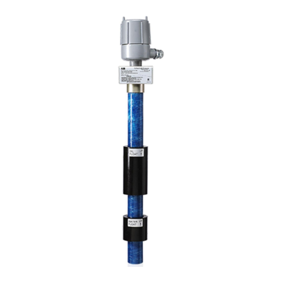
- Page 1 User manual Liquid level sensor with batteryless float support LevelMaster 7100 Accurate and reliable measurement of storage tank liquid level for custody transfer and tank level management applications...
-
Page 3: Table Of Contents
Contents Typographical conventions ..........................vi Additional information ............................vii Health and safety ............................1 General information and notes ..........................1 Safety, warning, and note symbols........................... 1 Safety requirements for installation .......................... 2 System description............................3 Overview ................................3 General specifications ............................. 4 LevelMaster components............................ - Page 4 Applying power to the LevelMaster ........................37 Grounding ................................37 Configuring LevelMasters using MasterLink ..................... 39 Installing MasterLink ............................. 39 Connecting to the LevelMaster ..........................39 Configuring the first LevelMaster ........................... 41 Configuring additional LevelMasters ........................48 Configuring the host controller ........................50 Activate the LevelMaster application ........................
- Page 5 Replace floats ............................... 77 Replace the sensor assembly ..........................78 Move a LevelMaster from one tank to another ......................80 Troubleshooting ............................81 Appendix A Tank level pass-through ......................86 A.1 LevelMaster protocol commands ........................... 86 A.2 Activating the tank level pass-through ........................87 Contact us ................................
- Page 6 Figure 32: Totalflow CSA-certified barrier board ....................35 Figure 33: Wiring the LevelMaster to the barrier board ..................36 Figure 34: LevelMaster wiring to different types of ABB Totalflow host controllers through a safe barrier....37 Figure 35: Grounding the electronics board ......................38 Figure 36: Cable and adapters for local communications (2104836-001 boards) ............
- Page 7 Figure 48: LevelMaster application Communications tab ..................53 Figure 49: LevelMaster application request block files ................... 54 Figure 50: Verifying level and temperature measurements are received by host controller ........56 Figure 51: Determining register address for LevelMaster measurement values (Levels tab) ........57 Figure 52: Adding a variable (measurement) to trend ....................
-
Page 8: Typographical Conventions
Typographical conventions Element Convention Example Hyperlink the figure or table label and Cross-reference to a figure or table in the number. If the figure or table is not See Figure 2, or See Table 3 (page 12). document immediately following the cross-reference, add the page number where it is located. -
Page 9: Additional Information
Additional information Additional free publications and user interface software for the sensor are available for download at www.abb.com/totalflow or by scanning this code: Documents and user drawings for board part number 2104836 Part number LevelMaster startup guide 2105836 LevelMaster upgrade kit application guide (required for batteryless float support) -
Page 11: Health And Safety
For further information, or if specific problems arise which are not addressed in the instructions, please contact ABB. The content of these instructions is neither part of nor provided for changing a previous or existing agreement, promise, or legal relationship. All obligations on ABB result from the respective sales contract, which also contains the full and solely valid warranty clauses. -
Page 12: Safety Requirements For Installation
This manual does not address all the requirements for the installation of products in hazardous (classified) locations. Refer to the ABB Certification (installation) drawing that is indicated on the unit name plate and local and national electrical codes for installation requirements in hazardous (classified) locations. -
Page 13: System Description
The LevelMaster uses simple ASCII protocol for communications and, therefore, can be interfaced to nearly any host system. When used in conjunction with ABB Totalflow host controllers (remote controllers or flow computers), a wide range of data gathering and site automation applications are available. -
Page 14: General Specifications
The sensor casing or tube is manufactured with different materials, depending on the corrosiveness of the fluid. These fluids include, but are not limited to: culinary water, oils, solvents, or acids. LevelMaster 7100 User manual 2105835 Rev AA | 4... - Page 15 The onboard power port provides the connector to supply power to the LevelMaster. The power port supports connections to: An external power supply or ABB Totalflow control or measurement equipment such as remote controllers and flow computers. Serial communications (RS-485) port The onboard serial port is used for communication with other devices.
-
Page 16: Software Interfaces
The software interface used to collect and monitor the LevelMaster measurement readings when connected to the ABB Totalflow host controller is PCCU32. PCCU32 is the common user interface for the ABB Totalflow remote controller and flow computer family of products. -
Page 17: Installation Scenarios
Using PCCU32 PCCU32 is the primary interface for the family of ABB Totalflow host controller products. It is used to configure the controller to be able to support communication with the LevelMaster. A special purpose application, the LevelMaster application, is activated within the controller to request, receive, display, and store measurement data from the sensor. -
Page 18: Figure 2: Typical Levelmaster Configuration For General-Purpose Locations
The switch comes in four configurations based on the distance from the top of the tank to the float switch location: 12, 16, 24 and 36 inch. Figure 4 shows the 12-inch switch assembly. LevelMaster 7100 User manual 2105835 Rev AA | 8... -
Page 19: Figure 4: Installation With High Level Auxiliary Switch (12-Inch Option)
Figure 4: Installation with high level auxiliary switch (12-inch option) LevelMaster 7100 User manual 2105835 Rev AA | 9... -
Page 20: Installation
MasterLink software version 2.0 or later can be used for all board versions and it is required for support of batteryless floats. It contains default or generic configuration files for every sensor length available. LevelMaster 7100 User manual 2105835 Rev AA | 10... -
Page 21: Unpack And Inspect
IMPORTANT NOTE: If there is any damage to the shipping carton, keep the carton and packing materials until the contents are inspected and found to be damage-free. Inspect all of the shipping cartons for damage. LevelMaster 7100 User manual 2105835 Rev AA | 11... -
Page 22: Figure 6: Levelmaster Components In Typical Installation
Compare the packing list with the materials received. Check for missing or incorrect parts. To report any discrepancies, call the ABB office listed under Contact us on the back cover of this manual. IMPORTANT NOTE: Do not return equipment to ABB without prior written consent. Returns are subject to the terms and conditions specified by ABB. -
Page 23: Table 2: Levelmaster Parts List
Some parts may be connected to, or already installed in, other individual parts, but should be accounted for before starting the installation. IMPORTANT NOTE: Components and replacement kits with other part numbers may be available. Contact ABB for additional details or if the list provided does not meet the site requirements. -
Page 24: Table 4: Cables And Adapters For Direct Connection To The Levelmaster
Verify that the correct cable and adapter are available for the installation. IMPORTANT NOTE: Variations of cable types with other part numbers may be available. Contact ABB if the list provided in Table 4 does not meet the site requirements. -
Page 25: Assembly
Tools and materials required: 24 inch pipe wrench Phillips screwdriver ® Teflon tape 2 wooden blocks to support the unit To assemble components on the LevelMaster before insertion into the tank: LevelMaster 7100 User manual 2105835 Rev AA | 15... -
Page 26: Figure 9: Cord Connector And Tank Port Bushing Installation
(it can be read) when the LevelMaster is in the vertical position. Not all floats include arrows indicating the position for insertion. If installing one float, see Figure 10. Figure 10: Single float assembly LevelMaster 7100 User manual 2105835 Rev AA | 16... -
Page 27: Install Or Set The Position Of The High Level Auxiliary Switch (Optional)
Verify that the high level switch assembly is installed in the tank port bushing. The installation should look similar to what is displayed in Figure 13. In this example a 12 inch switch installation is depicted. LevelMaster 7100 User manual 2105835 Rev AA | 17... -
Page 28: Figure 13: High Level Auxiliary Switch Installation
NO). If it is not in the desired position: Pull the retainer clip off. Turn the float over. Re-install the float switch. Place the retainer clip back into place. Figure 14: Auxiliary float switch for Normally Open (NO) operation LevelMaster 7100 User manual 2105835 Rev AA | 18... -
Page 29: Insert The Unit Into The Tank
LevelMaster can make it very difficult or impossible for a single installer to handle. The ideal situation incorporates the use of a crane. The following procedure assumes no crane. Prepare the tank for installation of the sensor prior to beginning assembly: LevelMaster 7100 User manual 2105835 Rev AA | 19... -
Page 30: Figure 16: Tank Port Bushing Installation
Ensure all fittings are tight except for the fitting on the top side of the tank port bushing. Figure 16: Tank port bushing installation Slide the cord connector down and screw into the tank port bushing. LevelMaster 7100 User manual 2105835 Rev AA | 20... -
Page 31: Figure 17: Nut And Body Installation
12. Plumb the conduit or cable for the wiring into the ¾ inch hub on the side of the electronics enclosure: For division 1 and 2 hazardous areas, use a conduit. For general-purpose areas, a cable with a cord connector can be used. 13. Proceed to section 4, Wiring. LevelMaster 7100 User manual 2105835 Rev AA | 21... -
Page 32: Wiring
The communication and power ports have removable terminal connectors for convenience. If the connectors are plugged in the ports when shipped, they can be removed for ease in field wiring (Figure 19). LevelMaster 7100 User manual 2105835 Rev AA | 22... -
Page 33: Figure 19: Removing Terminal Connectors (2104836-001)
Remove this jumper when connecting directly to the electronics board for local communication (during configuration). Once configuration is complete and local communication is terminated, the jumper can be placed again as required for the terminating sensor. LevelMaster 7100 User manual 2105835 Rev AA | 23... -
Page 34: Selecting Wire Type
To host controller RS -485 port: 1) Direct connection or 2) Through barrier T- T- T+ T+ POWER EARTH Figure 21: Wiring for communication with host controller (first or only LevelMaster) LevelMaster 7100 User manual 2105835 Rev AA | 24... -
Page 35: Figure 22: Wiring For Power (Single Board Installation)
The LevelMaster can be powered from an external power source or from the host controller (Figure 22). Figure 22: Wiring for power (single board installation) When using ABB Totalflow flow computers or remote controllers, power can be provided from their serial (COM) ports, eliminating the need for an external power supply. -
Page 36: Wiring Additional Levelmasters
CAUTION - Equipment damage. The output voltage (VOUT) at the serial (COM) ports on an ABB Totalflow flow computer or remote controller is dependent upon the external power supply connected to these devices. Before connecting the LevelMaster to these ports, ensure that the flow computer or remote controller input voltage does not exceed 15 Vdc. -
Page 37: Figure 23: General Schematic Of A Multi-Levelmaster Bus (General Purpose Location)
Insert the wires to the next LevelMaster in the inner (T+, T-) pair, second and third pin on J11. iii. Secure the inserted wires by tightening the screws on the connector. LevelMaster 7100 User manual 2105835 Rev AA | 27... - Page 38 LevelMaster. The communication connection is through the additional connection pair on the RS-485 port on the first LevelMaster. The first LevelMaster is an intermediate node. The additional LevelMaster is last on the bus and must be configured to terminate the bus. LevelMaster 7100 User manual 2105835 Rev AA | 28...
-
Page 39: Figure 24: Two-Levelmaster Rs-485 Bus Of Same Board Type Using Both Communication Contact Pairs
LevelMaster (instead of using both pairs as in shown in Figure 24). While using both pairs is recommended, this connection also works and is left up to customer preference. LevelMaster 7100 User manual 2105835 Rev AA | 29... -
Page 40: Figure 26: Two-Levelmaster Rs-485 Bus Of Same Board Type Using Single Communication Contact Pair
IMPORTANT NOTE: When wiring from the LevelMaster to the host controller, do not cut off spare wires. Tape them securely back to the cable jacket as spares, in case of damage. LevelMaster 7100 User manual 2105835 Rev AA | 30... -
Page 41: Wiring The Host Controller
LevelMaster(s) is being installed. CAUTION - Equipment damage. The output voltage (VOUT) at the serial (COM) ports on an ABB Totalflow flow computer or remote controller is dependent upon the external power supply connected to these devices. -
Page 42: Figure 28: Levelmaster Wiring To Different Types Of Abb Totalflow Host Controllers
RMC-2 RMC-1 Figure 28: LevelMaster wiring to different types of ABB Totalflow host controllers Examples of wiring to different ABB Totalflow host controllers Detailed wiring diagrams are provided in Figure 29, Figure 30, and Figure 31 included in this section. -
Page 43: Figure 29: Wiring The Levelmaster To An Xfc
Figure 29: Wiring the LevelMaster to an XFC Figure 30 shows how to wire the LevelMaster to either of the onboard COMM ports available on the RMC-100. Hot-swappable plugable modules must be installed and configured for RS-485 operation. LevelMaster 7100 User manual 2105835 Rev AA | 33... -
Page 44: Figure 30: Wiring The Levelmaster To The Rmc-100 (Onboard Comm Port)
This includes the Pin 1, VOUT. SENSOR DI/DO microSD NPort IA 5450AI RMC (2105350) Board Figure 31: Wiring the LevelMaster to Ethernet-to-serial converter and the RMC-100 LevelMaster 7100 User manual 2105835 Rev AA | 34... -
Page 45: Figure 32: Totalflow Csa-Certified Barrier Board
In hazardous locations, the LevelMaster can not be directly wired to the host controller or power supply. The LevelMaster and the host controller must be wired through a CSA-certified barrier board that can be purchased from ABB Totalflow. Figure 32 shows the barrier board, onboard connectors and pinouts. -
Page 46: Figure 33: Wiring The Levelmaster To The Barrier Board
Remove the J1 and J4 terminal connectors. Loosen the screws on the J1 and J4 terminal connectors. Insert the wires from the host controller in the correct connector pins. See Figure 34 for quick reference for ABB Totalflow devices. IMPORTANT NOTE: Wiring pinouts on ABB Totalflow remote controllers or flow computers vary depending on the model installed in the field. -
Page 47: Applying Power To The Levelmaster
Figure 34: LevelMaster wiring to different types of ABB Totalflow host controllers through a safe barrier Secure the inserted wires by tightening the connector screws. Insert the J1 and J4 terminal connectors back on the barrier board. Applying power to the LevelMaster After completing all the wiring and securing the wires in the terminal connectors, it is important to verify that the wiring was done correctly and that the LevelMaster(s) can be powered. -
Page 48: Figure 35: Grounding The Electronics Board
Figure 35: Grounding the electronics board LevelMaster 7100 User manual 2105835 Rev AA | 38... -
Page 49: Configuring Levelmasters Using Masterlink
Go to the Liquid level sensor LevelMaster 7100 link. This link is the LevelMaster product page on the ABB website. If no access to the website is possible. See the Contact us section in the back of this manual for support. -
Page 50: Figure 36: Cable And Adapters For Local Communications (2104836-001 Boards)
9V Batt 9V Batt Connect to laptop: Connect to LevelMaster 1. Serial or P/N 2018546-005 2. USB (using additional adapter ) Figure 37: Cable and adapters for local communication (2018546-005 boards) LevelMaster 7100 User manual 2105835 Rev AA | 40... -
Page 51: Configuring The First Levelmaster
If wishing to save the factory configuration and calibration data before making any changes, perform the procedure in section 8.9, Preserve sensor data and configuration. LevelMaster 7100 User manual 2105835 Rev AA | 41... -
Page 52: Figure 39: Masterlink Main Screen
If no location exists or a new location is to be used, right-click inside the screen (white area) and select Add New Location. Enter up to 25 characters for a location name. LevelMaster 7100 User manual 2105835 Rev AA | 42... -
Page 53: Figure 40: New Levelmaster Setup
If unable to communicate, see the contact information on the back of this manual for support. LevelMaster 7100 User manual 2105835 Rev AA | 43... -
Page 54: Figure 41: Masterlink Monitor Tab
13. In the New LevelMaster ID field, type a number from 1 to 99 for the ID. Take note of the ID used and ensure it is not used for any of the other LevelMasters on the site if all are connected on a common RS-485 bus. Each ID on the bus must be unique for communication to succeed. LevelMaster 7100 User manual 2105835 Rev AA | 44... -
Page 55: Figure 43: Rs-485 Termination
If connecting to an ABB Totalflow host controller, proceed to section 6, Configuring the host controller. If the unit is not connected to an ABB Totalflow host controller, proceed to calibrate the unit or add level bias in section 5.3.3, Calibration (standalone installations only). -
Page 56: Figure 44: Configure The Levelmaster To Terminate The Rs-485 Bus
If connecting to an ABB Totalflow host controller directly or through the RS-485 bus, proceed to section 6, Configuring the host controller. 10. If the unit is not connected to an ABB Totalflow host controller, proceed to calibrate the unit or add level bias in section 5.3.3, Calibration (standalone installations only), next. - Page 57 Under Read data from the LevelMaster and save them to file, use the default path and file name displayed or select a different path and/or user-defined file name. (If changing the name, ensure the file keeps the .dat extension.) The default name is the base serial number of the LevelMaster. LevelMaster 7100 User manual 2105835 Rev AA | 47...
-
Page 58: Configuring Additional Levelmasters
Proceed to configure the host controller for communication with the LevelMaster(s) in section 6, Configuring the host controller. Configuring additional LevelMasters IMPORTANT NOTE: Make sure that the units have the correct RS-485 termination configuration. The last unit must terminate the bus. LevelMaster 7100 User manual 2105835 Rev AA | 48... - Page 59 5.3.6, Save the location file with a different name. Ensure a unique ID is assigned to the LevelMaster. Repeat steps 1 through 4 for each additional LevelMaster. LevelMaster 7100 User manual 2105835 Rev AA | 49...
-
Page 60: Configuring The Host Controller
Configuring the host controller The procedures included in this section describe the configuration of the ABB Totalfllow host controller to support the LevelMaster. The host controller can be a flow computer or remote controller in the Totalflow product family. The term host controller may be used to refer to either type of product. - Page 61 15. Click Send to save and activate the LevelMaster application. 16. Select OK, when prompted. The LevelMaster application displays in the list and is shown in the navigation tree (Figure 46). LevelMaster 7100 User manual 2105835 Rev AA | 51...
-
Page 62: Set Up General And Communications Parameters
On the Setup tab, the value of the Device/APP ID may be changed. Any name change will be reflected in the tree-view. (Figure 47). Type the number of tanks that will handled by the application. Figure 47 displays an application handling 2 tanks. Click Send. LevelMaster 7100 User manual 2105835 Rev AA | 52... -
Page 63: Figure 47: Levelmaster Application Setup Tab
Click Send. This will assign COM port 2 to the LevelMaster. IMPORTANT NOTE: Based on the configuration files that were loaded onto the board, the remaining field default values should be sufficient to begin operation. Figure 48: LevelMaster application Communications tab LevelMaster 7100 User manual 2105835 Rev AA | 53... -
Page 64: Set Up The Levelmaster Request Blocks Files
13. Repeat steps 2 through 12 if setting up more than one tank. Rename the file for each tank set up in step 2. 14. When files for all tanks are created and saved, proceed to configure the LCD display. LevelMaster 7100 User manual 2105835 Rev AA | 54... -
Page 65: Configure The Lcd Display
Perform this procedure to verify that the host controller is communicating with the LevelMaster. If communication is taking place, level measurement(s) should be displayed. To verify if measurements are being displayed: Make sure the LevelMaster and the controller are connected. LevelMaster 7100 User manual 2105835 Rev AA | 55... -
Page 66: Configuring For Data Collection
In installations with a Totalflow host controller, communicate with the host controller and obtain the LevelMaster data it has received. The host controller trend application can be configured to store the LevelMaster data. LevelMaster 7100 User manual 2105835 Rev AA | 56... -
Page 67: Figure 51: Determining Register Address For Levelmaster Measurement Values (Levels Tab)
At the Trend Variable Configuration Window (Figure 52), type the desired variable parameters and register address determined in step 2 above, and click OK. The variable name and its units (if defined) are listed. LevelMaster 7100 User manual 2105835 Rev AA | 57... -
Page 68: Figure 52: Adding A Variable (Measurement) To Trend
Each variable defined in the trend file can be edited and corrected, or the variable can be deleted and redefined with the correct information from the Trend System screen. LevelMaster 7100 User manual 2105835 Rev AA | 58... -
Page 69: Save The Configuration
To save the configuration files for a G3 flow computer: Ensure that the Enable Memory Backup pins located on the flow computer board are set correctly. See the G3 user’s manual or the PCCU32 help files for more information. LevelMaster 7100 User manual 2105835 Rev AA | 59... -
Page 70: Duty Cycling Power (Optional)
Read Now DI and Round To parameters. These may be used and set at other times. IMPORTANT NOTE: See the Contact us information on the back of this manual for support with this configuration. LevelMaster 7100 User manual 2105835 Rev AA | 60... -
Page 71: Push-To-Read (Optional)
Figure 55: Host hardware digital inputs IMPORTANT NOTE: See the Contact us information on the back of this manual for support with this procedure. LevelMaster 7100 User manual 2105835 Rev AA | 61... -
Page 72: Calibration From The Host Controller
MasterLink, it is recommended that level calibration be performed from the host controller and not the MasterLink. To add level bias at the host controller: On the navigation tree, expand Tank Data. Select the Levels tab (Figure 56). Figure 56: Adding level bias from PCCU LevelMaster 7100 User manual 2105835 Rev AA | 62... -
Page 73: Calibration For Volume Calculations
On the Calibrate tab, scroll down to locate the No. of Tank Sections (Figure 57). The default is set to 0. Select the value field and type the number of sections (1-10). LevelMaster 7100 User manual 2105835 Rev AA | 63... -
Page 74: Figure 57: Configuring The Strapping Table
On the navigation tree, click LevelMaster. Verify the volume calculations are displayed. 10. After all calibration is complete and verified, save the controller configuration as described in section 6.7, Save the configuration. LevelMaster 7100 User manual 2105835 Rev AA | 64... -
Page 75: Service And Maintenance
If powered from the serial (COM) port on a remote controller or flow computer, disconnect the LevelMaster from that port. If connected through a barrier board, disconnect the LevelMaster from the barrier board. LevelMaster 7100 User manual 2105835 Rev AA | 65... -
Page 76: Remove Field Wiring
Remove the cable or conduit from the base of the electronics enclosure. The removed wires will hang at the end of the conduit. Position the conduit safely until ready to install back into the enclosure and restore wiring. LevelMaster 7100 User manual 2105835 Rev AA | 66... -
Page 77: Restore Field Wiring
Lay the unit on the ground using the wooden blocks underneath for support. (If no wooden blocks are available use any stable and even support to keep the unit from rotating while in a horizontal position). If changing floats or the internal sensor assembly, proceed to the appropriate procedure. LevelMaster 7100 User manual 2105835 Rev AA | 67... -
Page 78: Reinstall The Unit Into The Tank
Figure 60: Removing electronic enclosure from casing Hold the enclosure with the other hand and rotate counter-clockwise. Do not stop holding the enclosure as it detaches from the casing to avoid pulling the sensor cable. LevelMaster 7100 User manual 2105835 Rev AA | 68... -
Page 79: Reinstall The Enclosure On The Casing
IMPORTANT NOTE: The cables designed to connect the laptop to the board provide power to the board through one or two 9 Vdc batteries. Always ensure that the batteries are charged. Make sure to connect the positive LevelMaster 7100 User manual 2105835 Rev AA | 69... -
Page 80: Preserve Sensor Data And Configuration
A file created to preserve the factory calibration the unit was shipped with can also be used. If this file was saved before configuration was performed however, it will not have the field configuration and the LevelMaster will have LevelMaster 7100 User manual 2105835 Rev AA | 70... -
Page 81: Upgrade The Electronics Board
The following procedure assumes the following: The board is being replaced without removing the unit from the tank. LevelMaster 7100 User manual 2105835 Rev AA | 71... - Page 82 Bend the tab gently into a semicircle using the thumb and forefinger, making sure the apex of the arch is placed against the board while the ends of the tab are braced to the inside of the housing. LevelMaster 7100 User manual 2105835 Rev AA | 72...
-
Page 83: Figure 61: Masterlink Upload/Download Tab
Figure 61: MasterLink Upload/Download tab At the browser, navigate to the folder where the existing configuration file was saved (for example, C:\Program Files (x86)\ABB\MasterLink). If not modified or saved with a different name, the default file name will have the 5-digit base serial number. - Page 84 For example, for a 20 foot sensor with a 2018546-005 board, select the "dual_20ft.dat " file from the DefaultDat folder. For example, for a 20 foot sensor with a 2104836-001 board, select the "Dual_20ft_batteryless.dat" file from the 7.0 Head board folder (Figure 62). LevelMaster 7100 User manual 2105835 Rev AA | 74...
-
Page 85: Figure 62: Locating The Correct Factory Default Configuration File
Under Send Data to the LevelMaster from file, verify that the file path displays correctly (Figure 63). Figure 63: LevelMaster Upload/Download tab Click Download Data to LevelMaster. Click OK when the download is complete. LevelMaster 7100 User manual 2105835 Rev AA | 75... -
Page 86: Figure 64: Levelmaster Setup Tab For Id And Baud Rate Configuration
17. If connected to a Totalflow flow computer or remote controller, verify that no errors are displayed and that measurement readings are updated by the LevelMaster application (PCCU). 18. Reinstall the enclosure cover. LevelMaster 7100 User manual 2105835 Rev AA | 76... -
Page 87: Replace Floats
Slide the float clamp back onto the bottom of the casing. Use a Phillips screwdriver to tighten the clamp 1 inch above the bottom of the casing. Considerable force may be required to lock the clamp on tight. LevelMaster 7100 User manual 2105835 Rev AA | 77... -
Page 88: Replace The Sensor Assembly
Remove the casing from the support wooden blocks and position the new one on the blocks. Reinstall the enclosure on the new casing as described in section 8.7, Reinstall the enclosure on the casing. LevelMaster 7100 User manual 2105835 Rev AA | 78... - Page 89 CAUTION – Equipment damage: With this procedure, the sensor assembly coil is exposed when removed from the casing. When possible, it is recommended that replacement sensors be ordered from ABB to follow the procedure described in section 8.14.1, Replace sensor assembly and casing.
-
Page 90: Move A Levelmaster From One Tank To Another
11. If connecting to a Totalflow flow computer or remote controller, verify measurement readings and ensure that no errors are displayed in the LevelMaster application (PCCU). See section 6.5, Verify basic configuration. LevelMaster 7100 User manual 2105835 Rev AA | 80... -
Page 91: Troubleshooting
The MasterLink software displays errors messages in its Monitor tab which can help troubleshoot error conditions or component failure. Each condition has an assigned error code. Take note of the codes or messages displayed as they can help ABB support personnel or developers determine the cause of the problem. -
Page 92: Table 10: Troubleshooting New Installations
“floating ground.” The current (mA) in these cases will be near zero. Continuity can be checked to trace parted power wire problems. Be sure to trace the wiring for polarity before supplying power. LevelMaster 7100 User manual 2105835 Rev AA | 82... - Page 93 The two main groups of problems are: Hardware Software To help determine which types of problem(s) exist, see Table 11 for error conditions, checks, and procedures. LevelMaster 7100 User manual 2105835 Rev AA | 83...
-
Page 94: Table 11: Troubleshooting An Existing Installation
DANGER - Serious damage to health/risk to life. When performing service, or using a laptop in a classified area, ensure that explosive gasses are not present. Equipment required: Test box (2101403-001) LevelMaster 7100 User manual 2105835 Rev AA | 84... - Page 95 10. Reconnect the ribbon cable to the electronics board. 11. Set the board in enclosure. 12. Replace the yellow fiberglass tension support. ® 13. Reconnect the communication and power connector(s) (green Phoenix terminal connector). 14. Replace the enclosure cover. LevelMaster 7100 User manual 2105835 Rev AA | 85...
-
Page 96: Appendix A Tank Level Pass-Through
Table 13: Commands for TLPT for board part number 2104836-001 (firmware version 7.000) Command Description syntax U**? Measure displacement U**?? Measure displacement in endless loop U??? Measure displacement in old test mode LevelMaster 7100 User manual 2105835 Rev AA | 86... -
Page 97: Activating The Tank Level Pass-Through
For LevelMasters with boards whose firmware version is 5.015-5.018, use the commands listed in Table 12. For LevelMasters with boards whose firmware version is 7.000, use the commands listed in Table 13. 10. Press Enter on the keyboard after the command has been typed. LevelMaster 7100 User manual 2105835 Rev AA | 87... - Page 98 V0=+07765 V1=+01656 V2=+04361 V3=+08909 PC00548 F1 V0=-06447 V1=+05155 V2=-06952 V3=-07166 5 7 S00557 L02285 021 F0 V0=+07765 V1=+01656 V2=+04361 V3=+08909 2 3 S00245 L01113 010 F1 R=10727 T1=10950 T2=10762 T3=10733 T4=10722 T5=10731 LevelMaster 7100 User manual 2105835 Rev AA | 88...
- Page 99 R=10728 T1=10950 T2=10761 T3=10733 T4=10723 T5=10730 R=10728 T1=10950 T2=10765 T3=10733 T4=10726 T5=10730 R=10728 T1=10953 T2=10761 T3=10735 T4=10721 T5=10730 R=10727 T1=10953 T2=10763 T3=10735 T4=10723 T5=10731 DIST=022.93 TC=+000.00 F0 DIST=011.13 TC=+000.00 F1 U03D023.72D012.11F076E0000W0000Ca982 LevelMaster 7100 User manual 2105835 Rev AA | 89...
-
Page 100: Contact Us
Translated versions, in any other language, shall be maintained as accurately as possible. Should any discrepancies exist, the US English version will be considered final. ABB is not liable for any errors or omissions in the translated materials. Any and all derivatives of, including translations thereof, ABB Inc.